1. Introduction
Resilience is one of the ultimate objectives of sustainable design. A wide interpretation of resilience is that of a multi-faceted transdisciplinary concept addressing the complexity of decision making under the conditions of risk and uncertainty [
1]. A discussion of a relationship between social and ecological systems raises two aspects of resilience: (a) the capacity to quickly recover from disturbance and return back into original shape or performance, or (b) to regain equilibrium in a different state after adaptation process [
2]. Resilience has become particularly important as we experience unprecedented changes in our climate, and it has been researched in the context of buildings, cities, and urban environments.
Research into the zero carbon retrofit of residential buildings in the context of current and future climate [
3] identified that there is no single solution that will fit the current and future weather scenarios, and that gradual adaptation of buildings will be required.
On a site level, research into the effects of green plants on and around buildings has increased our understanding of their effect on the reduction of solar heat gain and the increase of internal comfort levels [
4]. Seeking the essence of this finding, this paper will analyze the relationship between solar radiation and transpiration from green plants, so as to quantify the potential for site resilience design.
The design of resilient cities has been researched in considerable depth by the Urban Futures Team [
5]. The approach to the notion of resilience was the resistance to future uncertainties. This was a qualitative approach to test the future performance of current sustainability interventions using several different scenarios. The time horizon for the evaluation of outcomes of sustainability interventions was set to the year 2050. By identifying causes and effects of solutions, the methodology identified the risks and opportunities for future resilience.
Research into complexity of cities [
6,
7] identified the rules of expansion and contraction of city models as a consequence of the operation of market mechanisms and investment interventions, thus increasing our understanding of the inbuilt adaptation properties of cities.
Research into urban resilience was carried out in the context of two diverging interpretations [
8]: one, that refers to the property of a system to regain an initial equilibrium without adaptation to disturbances, and the other, that refers to the system property to gain new equilibrium by changing the state, adapting to disturbances in a similar way as ecological systems. The work concluded that a greater recognition of ecological resilience would be required within the planning practice in order to achieve long term resilience of urban systems.
The effects of climate change on urban systems were analyzed in the context of complex networks [
9]. The work highlighted the need for reconfiguration of urban systems in response to event avalanches caused by climate change. The work on urban disasters, although in a different context, corroborated the need for local configuration and allocation of resources [
10]. A continuation of this approach will be one of the aspects of research reported in this paper.
In contrast to these and numerous other studies that look into specific aspects or resilience using a qualitative approach, the work presented here uses a combination of qualitative and quantitative approaches to give practical guidance to designers for achieving resilient designs.
The main objective of the paper is to qualify and quantify the key ingredients of resilience design of buildings, sites, and regions, in response to heat aspects of climate change, and to identify a common denominator between these three levels, thus helping to develop a holistic approach to resilience design of the built environment undergoing extreme weather events.
The intended outcome of this work is to create better designs for the future, which are capable of surviving climate change and extreme weather events without degradation of performance—designs that are capable of adaptation to changing conditions to provide comfortable living environment for people.
2. Materials and Methods
This section introduces the methods in three parts, corresponding to a building level, site level, and regional level resilience design.
2.1. Building Resilience Model Based on Multi-Objective Optimization
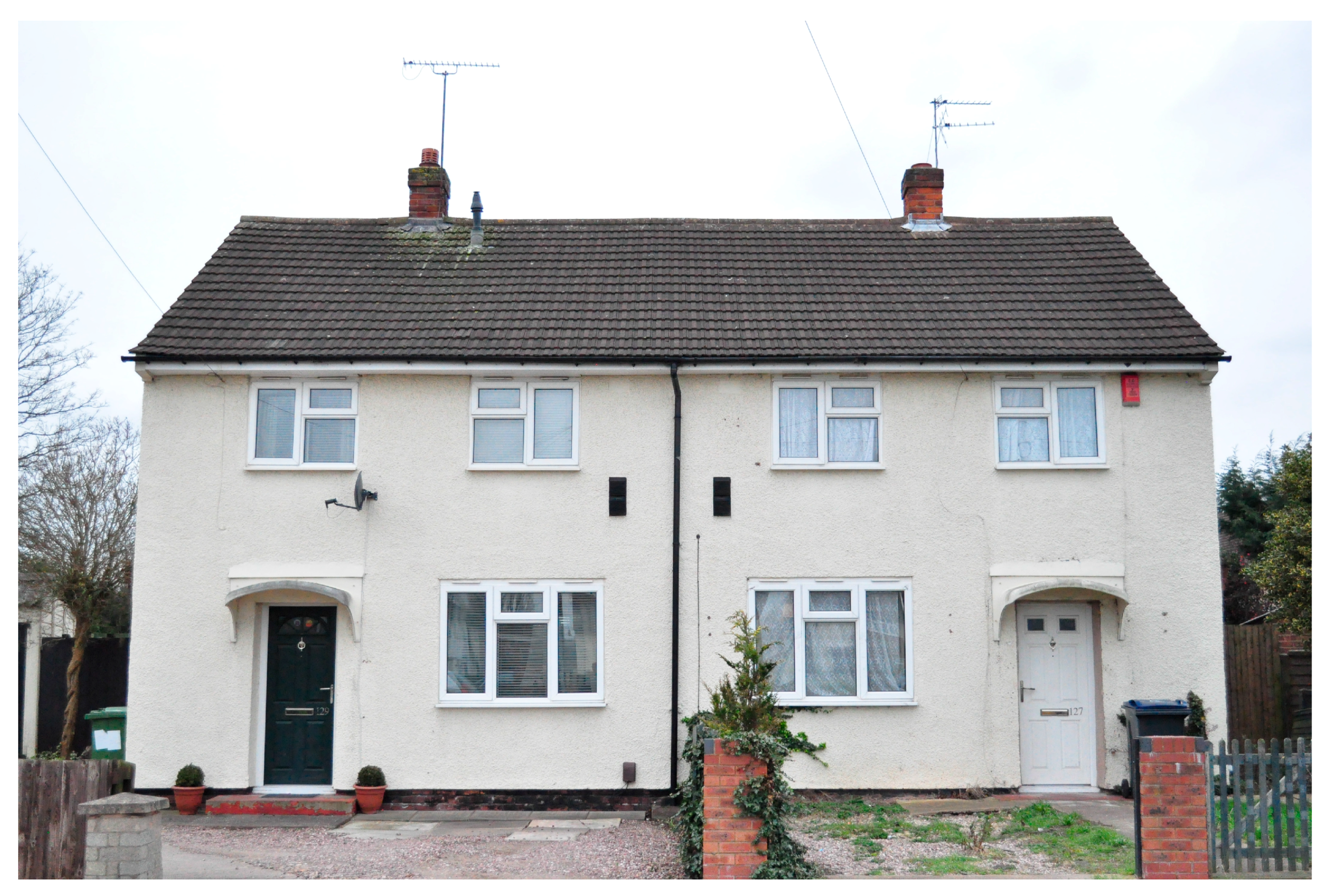
The method in this sub-section is based on a retrofit project called RetrofitPlus, completed in May 2017 (please see Acknowledgements for details). The subject of this retrofit are two semi-detached houses, referred to as House A and House B, owned by Birmingham City Council in the UK (
Figure 1). The original construction is Wimpey no-fines, developed for social housing after the Second World War. The wall construction is made from 300 mm concrete, without fine aggregates such as sand, which was the reason for naming it ‘no-fines’. The absence of thermal insulation is evident from the thermal image taken on site in February 2016 (
Figure 2), with high heat loss shown below the windows, corresponding to central heating radiator locations.
Retrofit design was carried out using multi-objective optimization in JEPlus + EA [
11], with EnergyPlus [
12] as the underlying simulation engine. The starting process in the retrofit design was the calibration of the simulation model, documented by Jankovic and Basurra [
13]. The calibration process achieved 99.83% accuracy in respect of electricity consumption, and 99.67% of accuracy in respect of gas consumption used for heating and cooking. The calibration of the simulation model was carried out using energy bills over a period of two years and hourly weather data for Birmingham. Multi-objective optimization was used for the calibration process, with parameter variation that ensured a wide range of performance outcomes. The combination of parameters that resulted in a nearly zero relative error for electricity and gas consumption was used as a calibrated set, and was taken forward as a starting point for retrofit design simulations.
Retrofit design was subsequently carried out, using technical and behavioral parameters in a multi-objective optimization process. The technical parameters were:
five different thicknesses of TCosy [
14] wall insulation: 100 mm, 150 mm, 200 mm, 225 mm, and 270 mm, combined in pairs with the identical TCosy roof insulation thicknesses;
infiltration air changes per hour;
fuel type (gas or biomass);
lighting power density;
two different PV arrays (East side of the roof only, and East and West side combined).
The behavioral parameters used were:
- 6.
room set temperature and
- 7.
clothing level.
The objective functions used for multi-objective optimization were CO
2 emissions and discomfort hours. The variation of the above parameters created a solution space of just over two million possibilities. The search of this solution space resulted in a design recommendation for 270 mm thermal insulation, and Passivhaus standard air tightness, as explained in
Section 3.1.
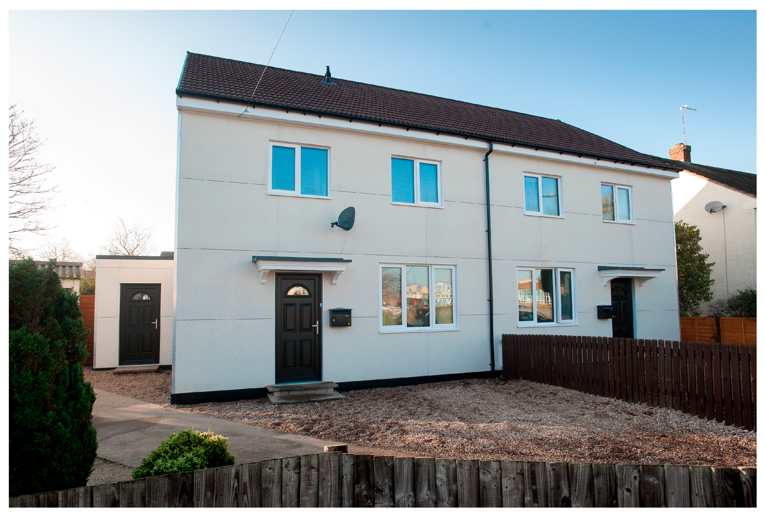
These parameters were subsequently applied to the manufacturing and installation of the thermal envelope, as shown in
Figure 3. The completed retrofit of the two houses is shown in
Figure 4.
The completed retrofit is characterized with U-values and air tightness shown in
Table 1, in comparison with pre-retrofit values. The table shows that Passivhaus air tightness of 0.6 ach was not quite achieved; however, the improvement of air tightness was by 3.4 times in House A and 6 times in House B.
At the time of writing this paper, post retrofit monitoring had not yet been completed, and the results of monitoring will be reported in a separate paper.
This now brings us to resilience design analysis of the two houses. The objective is to find out how the houses will respond to future climate, and therefore the optimization process was re-run with the same technical and behavioral parameters listed above, and with four different weather files for Birmingham: current weather, and future weather for years 2030, 2050, and 2080. The analysis of results will enable us to investigate the resilience of this design to future extreme weather events, and to identify design parameters that will ensure future resilience.
2.2. Site Resilience Model Based on Balance between Solar Radiation and Evaporative Cooling from Green Plants
Site resilience is studied using a balance between incoming solar radiation and evaporative cooling capacity of green plants. Maximum horizontal total radiation in W/m2 is determined from hourly weather data files in EnergyPlus weather format (EPW) for the current climate and for future climates in years 2030, 2050, and 2080. Typical plant transpiration is also determined in kg/(h·m2) and cooling capacity from transpiration is calculated using latent heat of evaporation of water from the plant leaf. The cooling capacity obtained in W/m2 of the leaf surface area is then compared to the incoming solar radiation on the same surface area. Calculations of reduction of solar heating effect by cooling from plants are then carried out for all four climate years. The results are expressed in terms of leaf area required to completely eliminate the effect of solar heating on the ground, and in terms of percentage reduction of solar heating from the leaf area equal to the area exposed to solar radiation. This effectively develops the metrics for reducing the heat island effect.
2.3. Network Model Applied to Regional Resilience Design
Regional resilience design is studied using a network model based on random grammars, following the principles reported by Jankovic [
9], and extending the qualitative aspect of that work. The model uses binary strings (strings consisting of 1 s and 0 s) to represent raw materials, as well as transformations of these materials into processed resources. These transformations are carried out by models of artificial agents. The connectivity between the agents and the transformations of binary strings are governed by random grammar rules reported by Kauffman [
15]. These rules can be represented with the following pseudocode:
If (String B matches any substring of source String A) then
replace that substring of String A with String C.
This creates a transformed source String A’. The ‘if-then’ pairs of (String B, String C) are the grammar rules randomly generated and used by each agent.
The model maintains a resource pool and a product pool of binary strings throughout its operation. The resource pool is randomly initiated with binary strings at the start, and these strings remain unchanged throughout the model operation. A grammar rule acting on a resource string modifies it into a product string, thus populating the initially empty product pool, while a grammar rule acting on a product string removes the original and replaces it with the newly generated string. This ensures a constant supply of the resource strings, while the number of product strings will vary up or down.
In each time step during the simulation, one of the strings, either a product or resource, is selected at random, and passed on to a randomly selected agent. When an agent applies its grammar rules on a resource string, its color changes towards red, and when it applies the rules on a product string, its color changes towards green. Successful processing of a string (i.e., matching a substring in the source string and transforming it using grammar rules) makes the agent larger in size, while the agent size also decreases with time when no substrings are matched. Thus successful agents will grow and unsuccessful agents will shrink.
A connection between agents is made when an agent uses a string generated by another agent. Frequent connections between agents reinforce their link, represented by lines of increasing thickness, and the thickness of these links is reduced when no activity between two agents occurs.
In each simulation case, the length of resource String A is varied. The length of grammar rule string pairs is also varied within chosen boundaries. Network metrics parameters are then calculated for each of the simulation cases and interpreted in the context of resilience design.
3. Results
3.1. Building Resilience Simulation Results
Multi-objective optimization of the houses introduced in
Section 2.1 was run with four different climate years: current, 2030, 2050, and 2080. The parameter set introduced in
Section 2.1, together with the weather files, generated a search space of over eight million possibilities. The optimization objectives were set as Carbon Emissions in tons of CO
2 per year, and discomfort, in hours per year. The optimization process does not run an exhaustive search of all possible outcomes of the eight million simulations. Instead, a Genetic Algorithm (GA), based on NSGA2 [
16], searches the solution space and selects the most promising solutions. In this particular case, 850 solutions were selected by the GA out of eight million, as shown in
Figure 5. The minimum values of both objectives of these most promising solutions form a Pareto front of the points closest to the co-ordinate system, shown in red in
Figure 5a. These Pareto points were exported into a spreadsheet for individual climate years, and the resultant chart is shown in
Figure 6. Hovering above Pareto points reveals the ‘chromosome’ that creates each particular point—a combination of parameters that produced that point (
Figure 5b). From here, insulation thickness of 270 mm and Passivhaus standard air tightness were obtained as design recommendations. Acceptable discomfort hours were limited to circa 5% of the total annual hours.
The analysis of these best solutions in
Figure 6 shows that there is a general increase of discomfort hours as the climate years increase from current to 2030, 2050, and 2080. The analysis of the area circled in red in
Figure 6, in which the 2050 and 2080 points coincide, shows a reduction of thermal insulation from 270 mm under the current climate to 200 mm under 2050–2080 climate, while maintaining acceptable discomfort levels.
It should be noted that the ultimate goal for this design was zero carbon operation, ensured by renewable energy included in the simulation. This is evident from the horizontal axis scale in
Figure 6, which shows negative Carbon Emissions. The results were also checked with renewable energy switched off, but the relationship between the current and future discomfort levels associated with the same reduction of thermal insulation was consistent.
The implications of these findings will be discussed in
Section 4.1.
3.2. Site Resilience Analysis Results
Site resilience was studied using a balance between incoming hourly solar radiation and evaporative cooling capacity of green plants introduced in
Section 2.2, and the results are shown in
Table 2. The analysis is based on data for Birmingham, UK, but the same principles are globally applicable. First, maximum hourly solar radiation is found from weather data files for the current period, and for years 2030, 2050, and 2080, obtained from [
17]. These are shown in the first row of the table. The second row of the table shows typical plant transpiration rate obtained from [
18]. The third row shows the latent heat of water evaporation [
19]. The fourth row uses data from the second and third row to calculate plant cooling capacity from evaporation. Subsequently, the ratio (the balance) of solar radiation and plant cooling capacity is calculated in the fifth row. The results show that the plant cooling capacity is consistent between the current and future climates, and that 1.74 m
2 of leaf surface area can completely balance maximum hourly solar radiation falling onto one square meter. The sixth row of this table calculates the absolute reduction of heating effect of hourly solar radiation falling onto one square meter of horizontal surface area, resulting from evaporative cooling from the same leaf surface area of green plants. The final, seventh column shows the percentage reduction of solar heating by evaporative cooling. This reduction is consistent across different climate years and is circa 58%. The result indicates a considerable scope for reducing the heat island effect.
The implications of these findings will be discussed in
Section 4.2.
3.3. Regional Resilience Analysis Results
Regional resilience is analyzed using a network model introduced in
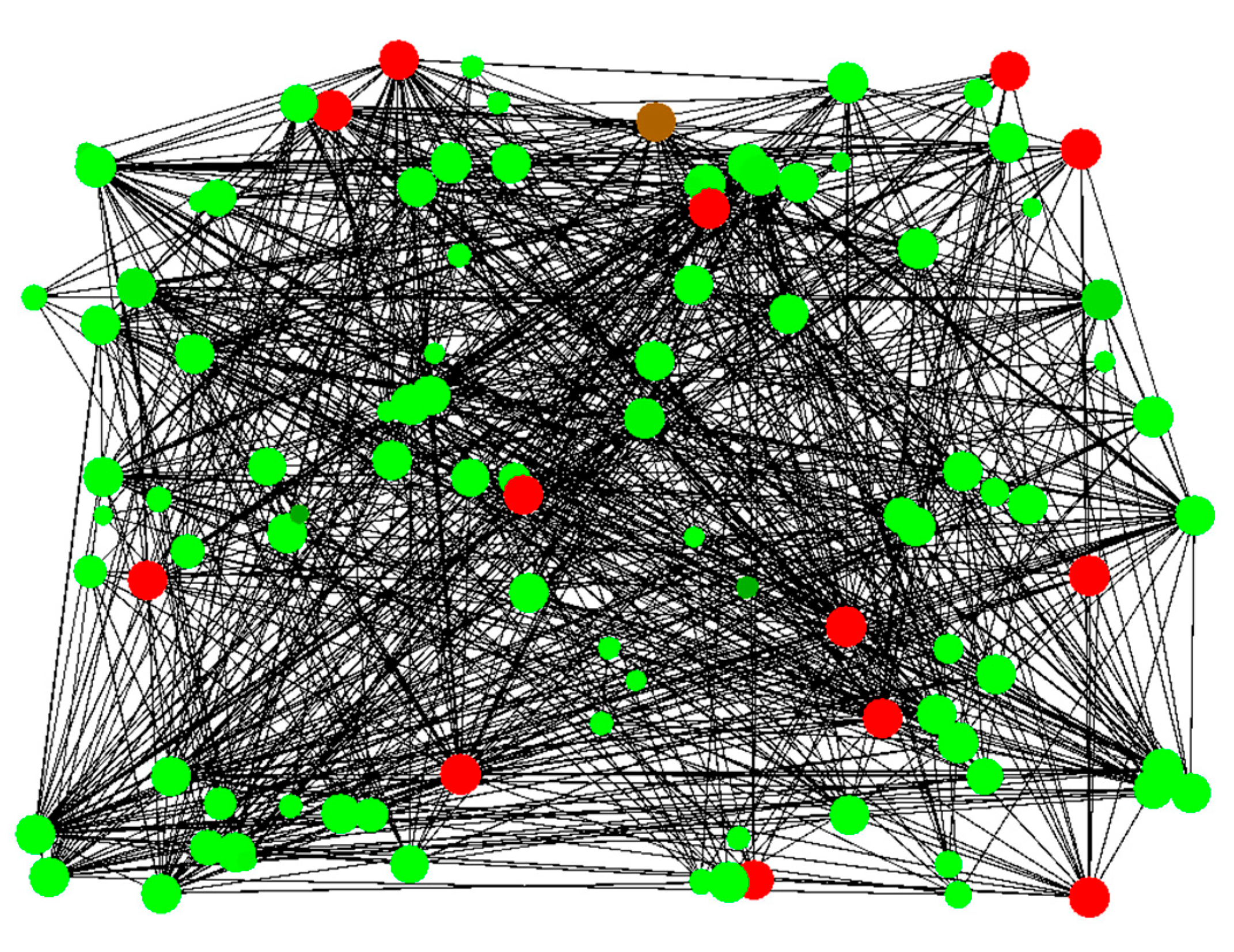
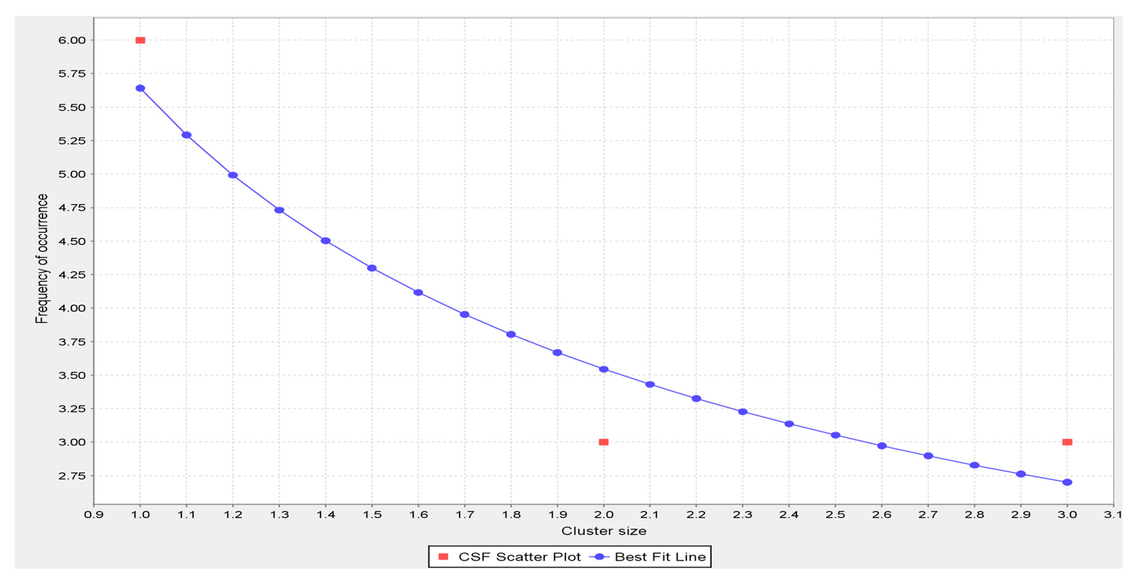
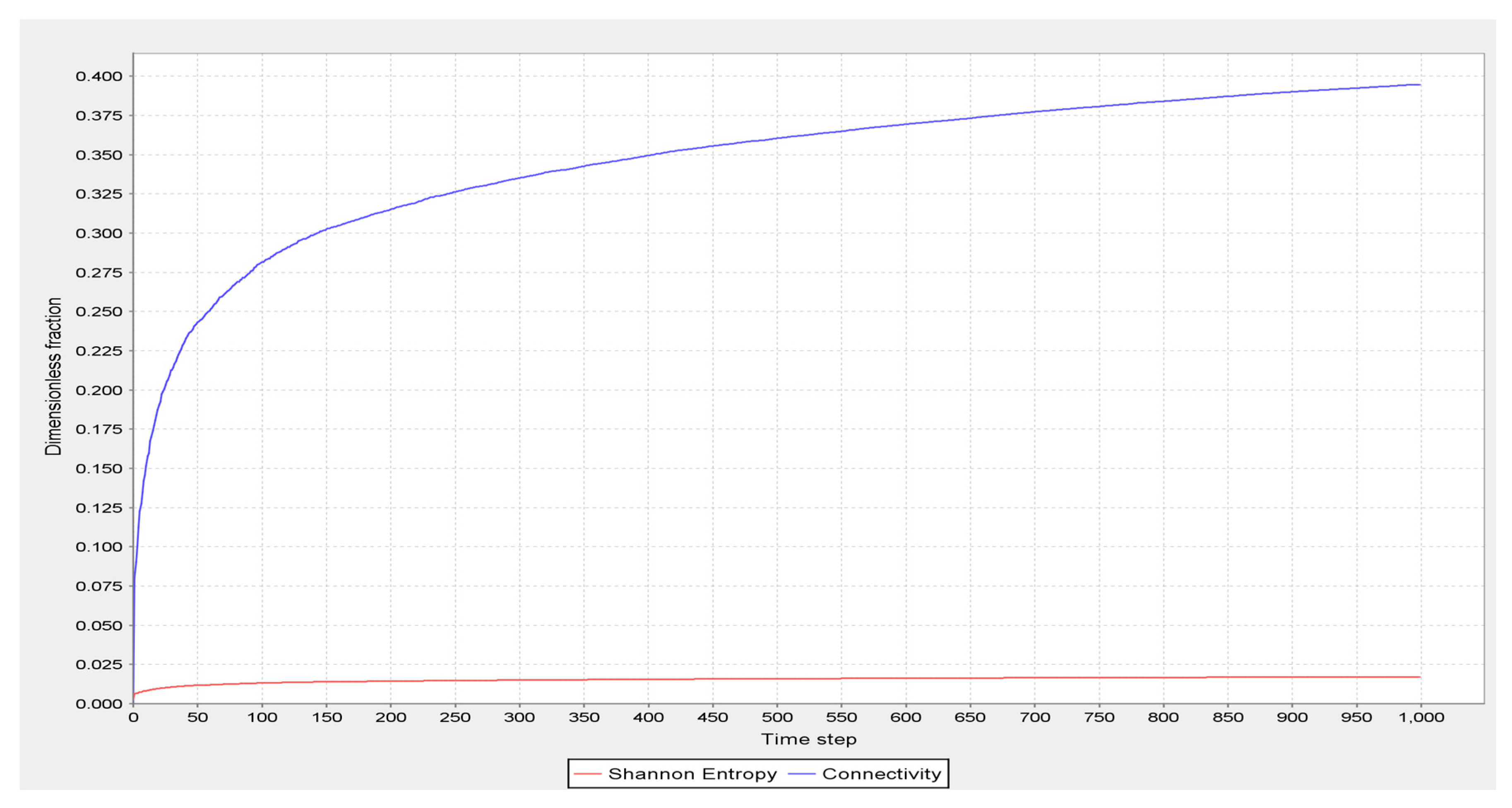
Section 2.3. Two cases are simulated: Case 1—densely connected network, and Case 2—sparsely connected network. The visual results of simulation of a densely connected network are shown in
Figure 7. Cluster size distribution in the densely connected network is shown in
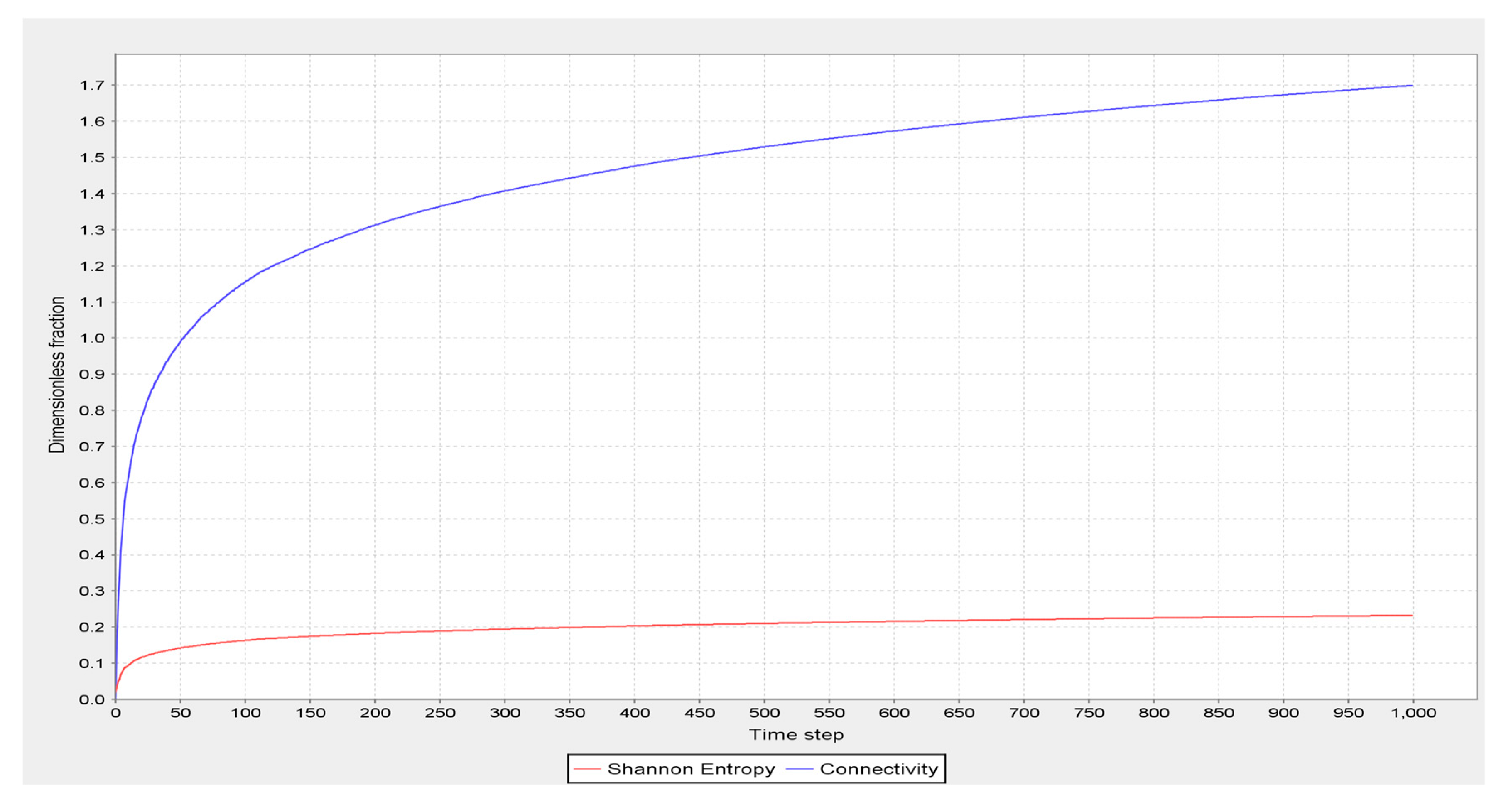
Figure 8, and Shannon entropy [
20] and connectivity are shown in
Figure 9. The visual results of simulation of a sparsely connected network are shown in
Figure 10. Cluster size distribution in the sparsely connected networks is shown in
Figure 11, and Shannon entropy [
20] and connectivity are shown in
Figure 12. Numerical results of network analysis are found in
Table 3. As it can be seen from
Table 3, densely connected network has a total of 20 clusters, compared with 11 clusters in the sparsely connected network. Shannon entropy, a measure of information transmission and storage capacity, and arguably a measure of complexity [
21], is much greater in the densely connected network. The same applies to the average connectivity per agent, which is also greater in the densely connected network, where each agent is, on average, connected to 1.6998 agents, and therefore to more than one other agent. The same table also shows that the largest local cluster is almost twice as large in the densely connected network. Lastly, the largest overall cluster of 68% of connected agents in the densely connected network is more than four times greater than the largest overall cluster of 21% of connected agents in the sparsely connected network.
Typically, a network will percolate throughout if the largest overall cluster is circa 60% of the connected agents or above, as discussed by Jankovic [
9] and elaborated by Weisstein [
22]. Having the largest cluster of 68% ensures that the entire network transmits a disturbance event throughout, including events arising from extreme weather. Inversely, the sparsely connected network, with the largest cluster of 21% of connected agents, will not transmit a disturbance event throughout, but such event will reach a limited depth in the network.
Both network topologies are useful, but not at the same time. As discussed by Jankovic [
9], normal operation of a network requires good transmission capability for desirable events. In the case of desirable events, it is therefore beneficial to have a densely connected network. However, when events are undesirable, such as those caused by extreme weather, a densely connected network may suffer widespread damage due to its good propagation properties. In the case of undesirable events, it is therefore much more beneficial to have a sparsely connected network where a damage from extreme events will be limited by the network topology to a small part of the network.
The implications of these findings will be discussed in
Section 4.3.
4. Discussion
4.1. Designing Building Resilience
The findings from
Section 3.1 point out towards resilient building design that responds to climate change. It appears that one of the ways of achieving building resilience is to reduce its thermal insulation in the future. In the case of retrofitted buildings discussed here, thermal insulation was injected into the hollow external cladding in the form of expanded polystyrene beads combined with an adhesive. The adhesive sets the beads shortly after the injection so that they do not leak through the openings, including the injection holes. However, vibrating the injected insulation with fluctuating air pressure will release the bonding effect of the adhesive and will separate the beads, thus effectively liquidizing thermal insulation. That makes it possible to extract thermal insulation from the cladding.
However, this will not produce a completely desired effect, as the building will still need a reduced amount of thermal insulation in future climates. An alternative solution could be to design the external insulation panels with sub-cavities of 50 mm thickness, into which the thermal insulation can be gradually injected and from which it can be gradually removed. Thus, thermal insulation could be scaled down from 270 mm, to 220 mm, and to 170 mm, and so on. This will create a resilient design that can adapt to long term climate change, and thus make buildings adaptable to increasingly extreme climate.
4.2. Designing Site Resilience
As it can be seen from the findings in
Section 3.2, plants have a considerable evaporative cooling capacity that is capable of completely balancing or significantly reducing the heating from solar radiation. A site design that is resilient to extreme weather needs to have a significant current and future provision for new areas of green plants, including green roofs, to reduce the effects of overheating from solar radiation, and thus mitigate the heat island effect. An ultimate provision for site mitigation would be to achieve 1 m
2 of green surface for each m
2 of hard surface. Although the calculations in this paper were carried out for Birmingham, UK, they are widely applicable to other locations and to current and future climates.
4.3. Designing Regional Resilience
The findings from
Section 3.3 point towards a resilient design of a region. In order to operate normally under desirable events, and limit the damage under undesirable events, a resilient network must be able to switch its connectivity from dense to sparse and vice versa. Typically, this means switching the average connectivity from each agent being connected to more than one other agent, to each agent being connected to less than one other agent, and vice versa. Normal operation requires dense connectivity, while sparse connectivity is required when extreme events occur. After extreme events have receded, recovery will be better facilitated if dense connectivity is re-established, even if the recovery does not lead to the initial state but to a new equilibrium.
A resilient design of a built environment region will therefore have adaptable connectivity in response to extreme weather events. Local facilities for quick deployment of resources, such as food, fuel, healthcare, and others need to be planned, and a degree of redundancy of these resources during desirable events needs to be accepted as the price worth paying, in order to enable quick deployment under extreme events, thus limiting the depth of impact of such extreme events. Closing existing local facilities on the basis of short term cost savings may therefore prove to be much more costly in the long run.
5. Conclusions
The paper has introduced and analyzed resilience design on the level of a building, a local site and a region. It is now the time to connect the dots.
The proposed resilient design of buildings has a provision for sub-layers in the thermal insulation layer, which may be redundant during normal conditions, but would become useful in a future climate when insulation thickness will need to be gradually reduced layer by layer. The proposed resilient design of local sites has a provision for new areas of green plants and green roofs, which may be redundant in current conditions, but would become very useful in a future climate to utilize evaporative cooling capacity of green plants and thus balance or mitigate the heating from solar radiation. The proposed resilient design of a local region has a provision for local facilities that may be redundant during desirable events, but which would be fully deployed during undesirable events arising from extreme weather, thus switching from long range connectivity to local connectivity.
This is where the notion of the shortest computer program comes in as a useful analogy. The shortest computer program is a binary string of 0 s and 1 s, which is designed to only performs a single task. Removing any bit from the shortest computer program will result in its catastrophic failure to perform the required task. However, if there is a degree of redundancy in this computer program, so that there are other binary bits in it, then the program is no longer the shortest and there is a degree of redundancy in it. Removing a single bit from such a program may not lead to its catastrophic failure, thus illustrating the essence of resilience.
Similarly, design or resilient buildings, resilient local sites, and resilient regions need to include a certain degree of redundancy, so as to enable adaptation to extreme weather events, and to be able to either recover or to re-establish equilibrium under new conditions, thus achieving long term resilience.
Future research will involve evaluation of resilience capabilities of specific buildings, sites, and regions using the findings from this paper, thus ‘pressure testing’ case study examples. Costs of achieving resilient designs will be evaluated in the context of the costs of consequences of non-resilient designs, and guidance for policy makers will be developed.


