1. Introduction
Since man had the courage and technology to sail far beyond rivers into the open sea, he needed a refuge for his ships, whether natural or artificial. Both conquests and trade made it increasingly necessary to rule the waves and, therefore, the ports.
So, different types of port began to be built. One of them consisted of using caissons or similar methods. These caissons were sunk onto their final site to then be filled with earth, Roman concrete (
opus caementitium) or granular material (see
Figure 1). This technique was then forgotten until we were well into the Renaissance.
In fact, as from the 15th century, testimonies once again appeared appealing for the development of breakwater construction technology. Amongst them, the development of a rapid quay construction technique was an obvious inclusion. This technique used the sinking of vessels or caissons as its prime performance. From this century on, there have been treatises describing the port construction process in increasingly more detail using this recourse.
Materials, auxiliary resources and construction technologies were developed throughout the centuries. However, the concept persisted. The majority of the changes were mainly related to the material depending on their use and availability in different ages.
At the end of the 19th century, timber and the Romans’ opus caementitium gave way to metal caissons. These were later dominated by concrete, which led to new shapes adapted to the different breakwater uses, as well as industrialization of the construction process. The result was an optimization of costs and performance.
Over the last decades of the 20th century, the increasing pollution and the consequent global warming made necessary to take measures in order to reduce the emissions of CO2 and other greenhouse gases. Therefore, the civil engineering field has not been unaware of contributing to reach that goal. In relation to the construction of caissons breakwaters and marine structures in general, eco-friendly concretes were introduced, which implied the use of sustainable supplementary cement-based materials and additions.
In the 21st century, with the continuous development of materials technology, fibre construction became an alternative means, an example being the cylindrical mooring dolphins recently placed in the Canary Isles (Spain). It is important to emphasize that this new material contributes to sustainability from the point of view of the less time and complexity related to the construction operations, as well as the lower volume of reinforced concrete used in the construction of the caissons. Furthermore, regarding these new materials used in the maritime industry, their development may lead us to recommence the cycle and sink “boats” to build breakwaters as the Romans did.
In view of that, this research work would like to cast an historical light, as complete as possible, on this caisson technology in order to know what was already done, which has often been reinvented again and again, either by forgetfulness or lack of knowledge, and its future, keeping in mind its contribution to sustainability; let us avoid “all novelty is but oblivion” [
3] happening to us.
2. The Roman Age
The caisson was first used in Roman times. The first written references are referred to the Battle of Brindisi in the siege Julius Caesar laid on that city [
4]. A breakwater was quickly built to prevent the Pompeii fleet reaching the port. For the construction of this breakwater, caissons were towed to the final site. After that, they were filled with earth to allow the access of troops and war material, as can be seen in
Figure 2. The Latin term used for these boats “
ratis” is interpreted differently in the work of Michel Reddé [
5], where pontoons are referred to more than caissons. Nevertheless, filling them with earth for troops to cross over would suggest that these boats probably hit the bottom, forming a provisional breakwater somewhat similar to caissons. Obviously, there was not a term on its own to define them, as it was the first time they were used.
As would occur centuries later in the Normandy landings, this breakwater was built in record time: “Caesar had almost half of his construction finished after just nine days when the ships returned to Brindisi sent by the Consuls. They carried the first part of the army to Durazzo” [
4].
In this case, efforts yielded no results since Pompeii managed to arrange for most of his troops to be evacuated by sea. However, this does allow us to situate a first example of caissons in marine works which, as in the case of the Normandy landings, used port construction technology for the purposes of war.
Later, this system was mentioned in “
De Architectura” by Vitruvius. It was referred to as one of the three appropriate types of systems for building breakwaters. It is interesting to recall that Vitruvius was an engineer both for Julius Caesar and for his successor, Caesar Augustus. He had the Codex dedicated to him. This book catalogued the whole of the knowledge available in that age. It included Roman port engineering, the legacy from previous cultures dominating the Mediterranean, such as Phoenicia and Carthage. This is the first technical book which mentioned caisson technology and it approximately dated from the 30th year before our age. Drawings on the three types of port can be found in the translation of the ‘Ten Books on Architecture’ rendered by Perrault in 1761 [
7], and in
Figure 2 the one referring to caissons is shown.
Moreover, there are other Roman references to caissons sunk to such effect. For example, double walled floating caissons were used in the port of Caesarea Marítima or Sebastos [
8] which King Herod ordered to be built (
Figure 1). The cream of Roman engineers participated in this scheme in which, once the caissons had been sunk, they were filled with concrete [
6].
After reading the paragraph by Flavius Josephus where the port’s construction is mentioned, we do not directly find any further mention of caissons (he did not expressly speak of caissons, but, from the dimensions he gives, it is not very likely they would be stones of such a size) [
9].
As Oleson rightly mentions [
10], the caisson construction in the port of Caesarea Maritima is a “transfer of technology on a grand scale” between the Empire’s provinces in the first Century B.C. This gives us some idea of technical progress and its advanced strategy of expansion through knowledge. What Herod achieved had no forerunner in the East Mediterranean and not even Roman emperors achieved anything similar until 60 years later in Portus. Some more examples and evidences of the use of caissons in the Roman Age can be found in the amazing book “Building for Eternity” [
11].
Concrete caissons were made in Rome, in the port of Ostia. They acted as a base to the North breakwater arches to allow water to flow easily. The whole construction process of this port is highly historic in nature, not only for the interest regarding the topic of the present research, due to the caissons used, but also because of the large symbolic load of different items forming its construction. With a 20 m × 20 m × 10 m cross section and walls approximately 1.5 m thick, these caissons were built during the crossing between Puzzolo and Ostia, in the same vessel in which Caligula brought the Obelisk from Egypt to be set up in what nowadays is known as Saint Peter’s Square [
12]. According to references, this ship, the
Mirabilis navis [
13], was the largest ship sailing the seas at that time. It is suspected that this vessel was sunk and buried in order to erase any trace of its passing over the land of
Gaius Julius Caesar Augustus Germanicus (Caligula). The ship was sunk to form part of the harbour’s breakwater [
14]. According to some references, it was sunk where the North breakwater commences and, in the words of Testaguzza [
15], it formed the harbour’s central entry breakwater. More were sunk for the remaining breakwaters.
In any event, it would seem quite clear that it formed part of the breakwater, as was confirmed by Pliny the Elder [
16]:
“It was so long that it came to largely occupy the left hand side of the port of Ostia. In fact, it was sunk there under the rule of the emperor Claudius, forming three quays as tall as towers, which had been completely built on the ship, made on the way with Puteolos powder and transported there.”
In
Figure 3 we can find different views of Portus structure as the Cross section of Caligula’s ship at the Portus lighthouse breakwater [
15] and the schematics ground plan and the elevation of the north breakwater of the port of Augustus of Ostia, formed by four concrete caissons and an arch breakwater between them [
6].
According to Milne, caissons were also used in building the quays of the Roman port of London [
1] (
Figure 1).
Once this prolific Roman period had concluded, where an evolution in port construction and technology was seen, together with a search for construction systems in order to speed up and build at complicated sites, a great leap in history has to be made, specifically, until the Renaissance, to once again begin to see further mentions of this system.
3. From the Renaissance to the Enlightenment
This long period of stagnation ended with the Renaissance. A new way of looking at the world and the human being through humanism and science shrugged off the corset retaining them for centuries.
Port technology and the world of caissons were not alien to this new trend. Ideas or concepts already dealt with by the Romans commence to be seen once again. However, in many cases, they are considered as new within the new trend of contemplating the world again and seeking new solutions to problems.
So, in the 15th Century, Mariano di Jacopo, alias Taccola, also known in the
Quattrocento as the “
Sienese Archimedes”, again took up the concept of floating caissons and even completed sea borne structures to be placed on rock foundation sites in his books entitled “
De Ingeneis” and “
De Machinis” [
17]. Plates on this can be found in the work of Francesco di Giorgio Martini and Francesco L. Tarantino (
Figure 4) and as the article entitled “
La Ricerca sui portiromani in cementizio” says “with the republishing of Vitruvius’ book in the Renaissance, techniques for building quays and banquettes directly in water were the subject of continuous, tormented analysis”.
However, the first really specific compendium dealing in-depth with port matters is the Manuscript commissioned by Philip II of Spain and attributed to Juanelo Turriano, “
Veintiún libros de los Ingenios y de las Máquinas” (Twenty-one books of Devices and Machines) [
19].
Experts consider this work as the first treatise on hydraulics known to the world and the first with such an amount of general description of port technology [
8]. Apart from a whole series of techniques for building and providing foundations for maritime works, his books 19 and 20 specifically deal with several applications in the use of caissons which, taken to the final site, were sunk to form the foundations or core of a breakwater or quay. He stated that this alternative system was better than ship sinking, since it would not be easy to find such vessels in large numbers in order to form a harbour. The author attributed the idea to himself, but we should stress that the solution is not exclusive either to this author or even to this century. Juanelo’s book explains all the steps to be considered to use these items, how to construct them, protect them by means of caulking and even the sinking process by opening various orifices in the bottom of the caisson (A and B in the left part of
Figure 5).
He also describes how to build the breakwater foundation using both caissons and ships which, once sunk, form the breakwater bases (
Figure 5).
Having taken this long step in caisson technology and now within the period of Enlightenment, there is not only more theoretical documentation on the subject but also documents that demonstrate practical cases executed with this technique or treatises that show solutions to precise problems in the guise of detailed construction projects.
Marine technology was developed both for commercial and military requirements. It played a fundamental role in the siege of La Rochelle in 1627: building a breakwater by sinking ships then rubble mound filled acting as a base for a timber structure (
Figure 6). Called the Richelieu breakwater, it was designed by Clement Métézeau whose aim was to prevent protestants under siege in the city of La Rochelle by the troops of Louis XIII (amongst them, his musketeers) from eluding the blockade to which they were subjected [
20]; this shut down of the port reminds us of what Julius Caesar did in the port of Brindisi.
In 1685, Cornelius Meyer also gave an example of building a double-walled timber caisson (
Figure 6); this caisson would allow for dry inside construction and make it easy to build up masonry walls. Using caissons to facilitate in situ construction is a variant on the technique.
Navigating through the development of caisson technology, we arrive at the 17th Century, the Age of Enlightenment. Here can be found treatises and descriptions with much longer and precise explanations, perfectly demonstrating construction processes, precautions to be taken and details of performances and costs; in short, there was a heavy focus on engineering.
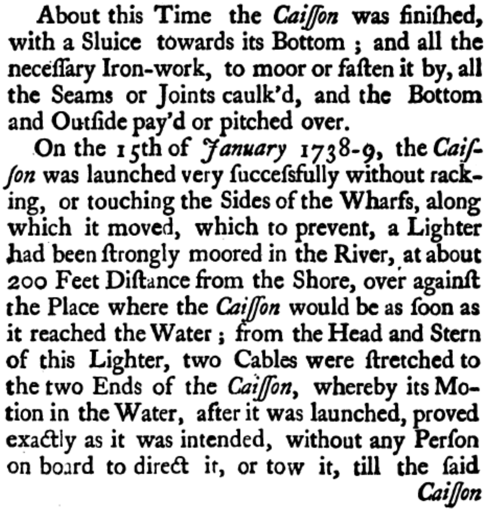
The book written by Charles Labelye who built the old London Westminster Bridge [
23] follows along this line and is often cited in later works in the same century. In this book, Labelye described down to the last detail all operations undertaken to build the bridge (
Figure 7). In particular, the pier foundations using the caisson system were dealt with. This system was chosen due to the site’s complexity and the depth, as well as the currents and tides and high winds raising large waves in that area of the Thames. This document also lets us share the important didactic work that Labelye had to perform, because he previously had to appear in a committee to convince them of how suitable and feasible this procedure was, compared with the pier piling method; the caisson system was a new development and had many detractors. Apart from the system’s technical feasibility, he had to argue how substantial would be the saving in cost and time to be achieved; but not only this, he also demonstrated the system’s reversibility as compared with the pile method should some fault occur.
This document includes several important elements. Amongst them, testing caissons and checking the foundation bed by sinking and refloating before the final sinking. It also included the re-use of caisson walls by dismantling and refitting them with the consequent saving in cost. This was emphasized in the text. The first caisson was positioned in 1738 and the bridge was opened in 1747.
In the 18th Century, the reference book was “
Belidor’s Architecture Hydraulique” [
24], where the Westminster bridge foundation drawing (
Figure 8) can be found. In Chapter XI of his Book III “where the construction of all works belonging to maritime squares” is shown, we find how to form foundations in the open sea or in rivers using dry caissons. Several cases of caissons are discussed, whether for building bridge foundations (Westminster) or for Nice and Toulon breakwater foundations (
Figure 8).
So, floating caissons were used for building the Toulon dry dock. They were gradually sunk as the masonry wall was being built up, just as the large caisson builders do nowadays for concrete caissons. Walls are built such that they can be easily removed. Their boards are reused and the base remains as the footing’s lost formwork; walls are only needed for two or three caissons, giving a consequent saving in their building.
Concerns are perceived in 18th Century constructions for costs, delivery periods, searches for the optimum solution and increasingly more detailed descriptions and drawings.
Thus, John Muller’s book, “Treatise on fortification” [
25], gave an itemised description of the “Method of building foundations with caissons in water” where he explained from how to moor the caisson at its final site to how bricklayers go about this work. The description follows the Westminster Bridge construction process and recommendations are allowed as to using the caisson method and its excessive cost for bridge piers. In this work, it is noted not only keenness for accuracy but constructive criticism to have the technique makes progress in the light of reason and experience.
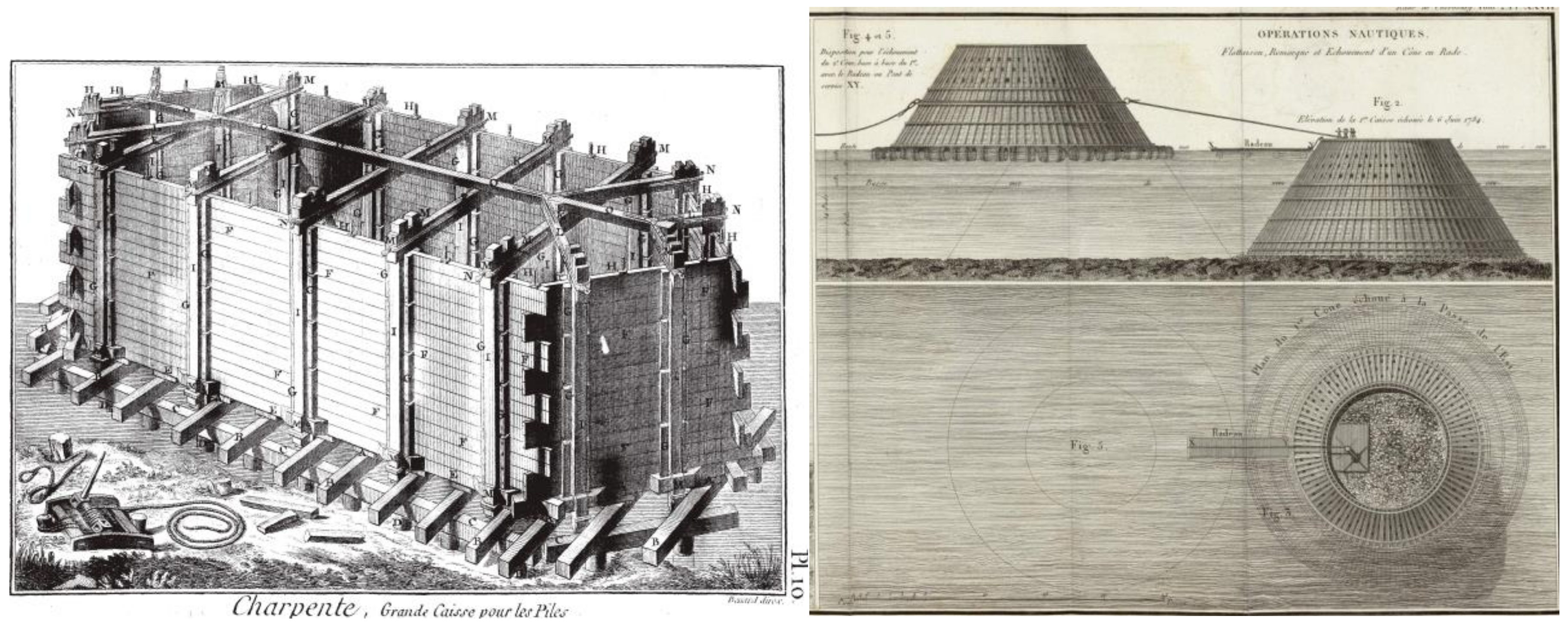
Diderot and D’Alembert’s “
Encyclopédie” [
26], a masterpiece bringing together the knowledge of that age also echoes this technology with a plate on the word “
charpente” (
Figure 9) where they present a caisson to act as a foundation for a bridge pier.
Over the 18th Century, increasingly more examples of the use of caisson techniques in breakwaters or quays can be observed. In some cases, they were projects which never passed the drawings stage or were not built in that way. Such is the case of the San Sebastian port extension designed by Pedro de Lizardi and revised by Julián Sánchez Bort, a disciple of the distinguished mariner and cartographer Jorge Juan, in 1773 [
28].
Other projects were indeed built, though with varying fates, such as the Cherbourg breakwater commissioned by Louis XVI to create a military dock basin from where the fleet which would invade England could be sheltered [
29]. The initial project drawn up by Louis-Alexander of Cessart addressed the use of 90 timber cones measuring 20 × 20 which were then sunk to form the breakwater and filled with rubble mound (
Figure 9); this project was “faced” by another, La Bretonnière’s, whose proposal was to sink ships to build the breakwater’s foundations [
27]. The first cones were destroyed by a storm and later on, the construction did not resist. So, after the French revolution, Napoleon Bonaparte decided to take up this construction work again using La Bretonnière’s system. The breakwater was concluded 70 years from its commencement in 1853 after several interruptions, under Napoleon III [
29].
Cessart’s book includes interesting plates on the cone construction process and how they were moored and sunk (
Figure 9), as was the method of the construction process of Saumur Bridge (
Figure 10). The book was published at the beginning of the 19th century [
27].
Wiebeking also presented drawings of the conical boxes used in the port of Cherbourg in one of his fabulous plates [
30], and caissons in Nice and Toulon, as can be seen in
Figure 11.
4. The Industrial Revolution and the Industrialization of Caisson Making
Whenever the Industrial Revolution advanced, it sought to optimise processes and use new, increasingly resistant and less costly materials and the port construction industry was not alien to these new developments. The pressing need for port expansion in Spain in the 20th Century would lead to the building contractors developing highly advanced techniques on a world level. They exceedingly optimised performances and costs whilst fabricating caissons of an increasingly greater size.
The first example of this evolution is the first-time-in-the-world building of metal caissons both in repairing the port of Madras in 1893, and using metal, cylindrical caissons of more than 12 m diameter and 16 high in the port of Bilbao extension in 1895–1896 designed by the engineer, Evaristo de Churruca (
Figure 12). This system was used in Bilbao since the traditional rubble mound system had undergone serious failures in the breakwater when storms lashed the area whilst it was being built; the new breakwater was built in the shelter of the original one. In the words of the engineer Churruca, using this system “a major modification to the superstructure’s construction system was made using large iron caissons which have not been used up to now in any work of this kind. Whilst the cost will increase somewhat, maintenance costs would notably reduce compared to the original system’s and its construction will be substantially facilitated” [
34].
This metal caisson system would be used again in the Port of Bermeo (Vizcaya-Biscay) in 1991.
The parallel-piped caissons used for the port of Bilbao were 13 m long by seven metres wide and seven metres high and were seated at a depth of five metres [
35].
Technical literature of the age expounds the features of the caisson, as well as the fact that the ballasting and towing process, up to its sinking, was not to change much in the future, since, once the caisson was made in different materials and by the various possible processes (both in dry and floating docks), its marine behaviours were identical, and it had to be ballasted according to its dimensions and stability so it could be towed to its final site. The system of sinking has evolved and is now carried out in a much more controlled manner using water pumps. This is different to the valve opening system used in previous centuries. The performances achieved with this new system are also shown in the current literature, allowing a relatively fast positioning of the caisson in five days.
Another example of metal caissons use is found in the port of Zeebrugge in (Belgium) [
38], where a steel framework was built. The walls and bottom were concrete lined inside to give unit weight and allow its centre of gravity to be lowered. They were built in several sizes, the biggest 18.60 m long by seven metres wide and six metres high.
The rise in size, speed of execution and performances seemed to be unstoppable by this point. This was due to the use of reinforced concrete as the precursor to a great leap forward. The great boom in this procedure at the end of the 20th century was materialised in a highly representative way in Spain, due to the extension of a large number of ports with far from negligible depths and wave conditions.
However, still at the beginning of the 20th Century, increasingly more examples can be found at different sites on the planet: concrete caissons were first used in Spain in the port of Barcelona in 1905, and this system was also used in the port of Rotterdam, in the port of Stockholm towards 1910, Rio de Janeiro, etc. [
39]. The caisson technique had extended at that time on a world-wide scale and, together with the consequent technological development, was now part of any engineering structure: optimisation of design, of materials, construction periods, research and development in order to adapt the concept of caissons to each project’s requirements. Port aspirations and a search for multi-uses increased whilst the development of caissons followed in this direction.
Extension works began in 1906 in the Japanese port of Kobe: “These caisson-blocks are built on the bank, lifted and thrown over a special floating dock and then towed to their site where they descend to the bottom and are concrete filled” [
37]. The system is not so very different to that used nowadays, all on the same platform (
Figure 11). These caissons measure 35.85 m long, the highest 12.65 m, and their average at the base is 10.80 m; they are made in three months. The fabrication and flotation process is a new development since the caisson is built on a platform with pile foundations. In this way, the floating dock made by the Kawasaki marine construction factory in Kobe takes the caisson from underneath (as if it were a fork lift truck picking up a pallet) and takes it on this floating platform to a site suitably deep to allow the dock to be sunk leaving the caisson floating.
Many systems were invented allowing increasingly larger caissons to be built in less time. The technological race was now completely launched. There are many 20th Century cases worthy of mention. Here, the most significant ones have been highlighted which provide some new developments in technology.
A clear example of increasingly larger, more ambitious structures is the dry dock of the port of Cadiz (Spain), whose construction started in 1929 [
39]. Restrictions on the size of the floating docks at that time led to breaking down into U-cross sectioned reinforced concrete caissons, some of them measuring 53 m × 17 m × 6.50 m, with 3200 tonnes displacement which were later joined to other blocks and towed to their final site where they were sunk. The caissons were designed by the engineer Ribera; Eduardo Torroja made the justifying calculation of reinforced concrete [
40]. Dimensions were now enormous and records were unceasingly broken.
In the Second World War’s Normandy Landings, the concrete-made floating Phoenix or Mulberry breakwaters, to use their code names, played a fundamental role and were used to build an artificial harbour for troops and materiel to disembark in record time (
Figure 13) [
41].
As the above mentioned port of Cherbourg enjoyed heavy German protection, a port was needed to allow allied troops and materiel to disembark. It had to be built in the shortest time possible. This was achieved by sinking those concrete caissons at Arromanches and Saint Laurent Sur Mer; two hundred and thirty (230) blocks were made in eight months in England by a team of English and American engineers. The whole project used 20,000 workers, employed by contractors including Balfour Beatty, McAlpine, Bovis, Nuttall, Costain, Taylor Woodrow Mowlem and Henry Boot. Consultants involved included Rendel Palmer and Tritton, Oscar Faber, Sir Alexander Gibb Mouchel and Halcrow [
41,
42]. The largest caisson measured 60 m long by 20 m high.
The old technique of sinking boats (so-called gooseberries) was also used that same disembarking D-day to create a first line of protection prior to that of the mulberries. We thus observe that history is cyclical, and concepts, wars, etc. are repeated: Julius Caesar, Richelieu, the Second World War, and so on. Unfortunately, there are too many references made to wars showing us milestones in the evolution of technology.
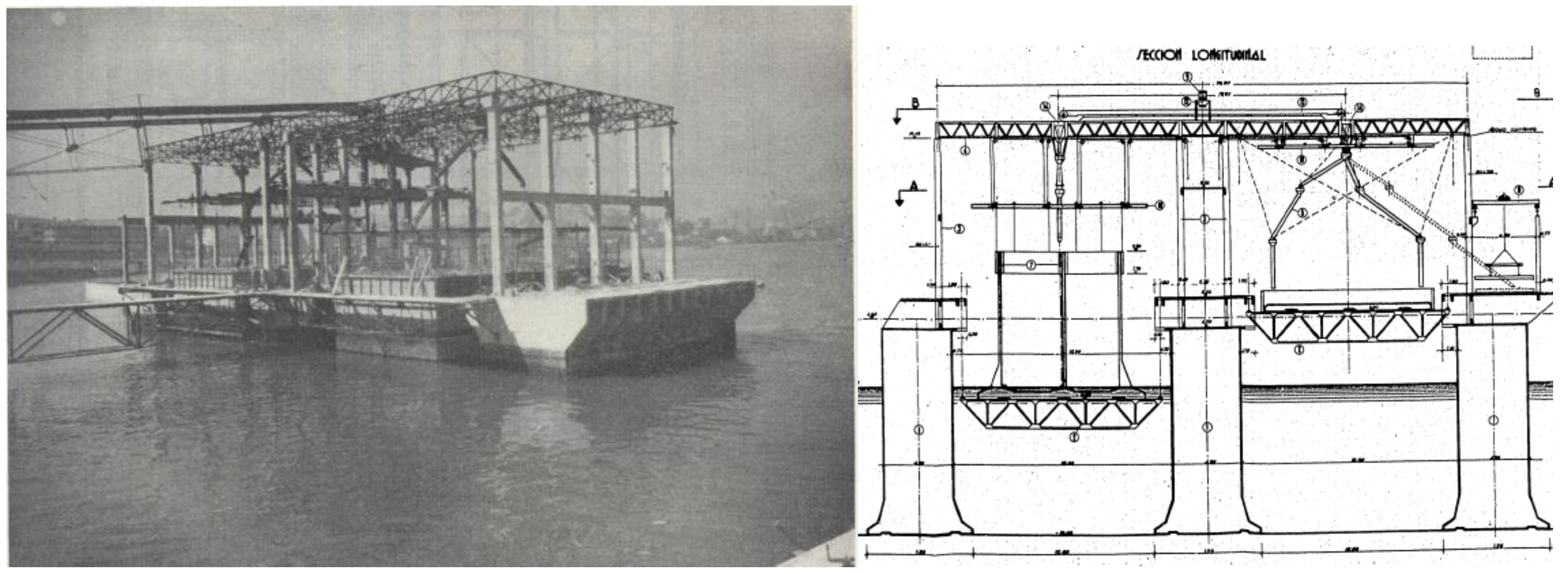
Another example are the sixty-five (65) concrete caissons 16 m high, 17.25 m long and 8.50 m wide which were built in 1958 in the port of Pasajes. Setting up a caisson building factory enabled two caissons per month to be launched (
Figure 14) [
43].
Such evolution brings us to modern concrete caisson building techniques where, by using floating caisson builders, large dimensioned caissons can be made. This is the case of the Acciona company’s Kugira caisson builder (
Figure 15) which, in a term of ten days, can make caissons of up to 67 m × 34 m with 32 m draught, which are unceasingly built from beginning to end [
44].
Dry dock building is also still being used to then launch caissons as if they were a ship or by the use of cranes. Lastly, huge dimensioned caissons have been required in some cases, but could not be built in these floating docks. They had to be mandatorily built dry. This was the case of La Condamine floating caisson [
46] in Monaco (
Figure 15) or the liquid gas terminal built in Algeciras.
5. Present and Future of Caisson Breakwaters Technology: An Important Field of Application for Sustainable Materials
The evolution of caisson technology is currently heading in two well-differentiated ways. The concept, though, is always the same as has been observed throughout history.
On the one hand, this development is related to the progress made in the characteristics of materials, especially due to the improvement of reinforced concrete performance, provided by the use of fibres as well as the incorporation of sustainable supplementary cement-based materials, amongst other advances in this field. On the other hand, the introduction of new materials, such as composite materials, which would also contribute to sustainability, breaks important new ground in order to continue innovating in the caissons building technology.
Regarding the relation between sustainability and the use of supplementary cementitious materials in the construction of marine structures in general and particularly for caisson breakwaters, it is mainly focused on the reduction of CO
2 emissions [
48]. It has been established that the manufacturing process of one ton of pure clinker (main component of ordinary Portland cement) produces the emission of approximately 0.89 tons of CO
2 to atmosphere [
49]. Therefore, the use of supplementary cement-based materials or additions, which totally or partially replace the clinker, would entail an important lessening of the above-mentioned emission of greenhouse gases. In the case of the execution of great civil engineering works, such as marine structures and caissons breakwaters, this contribution to sustainability is more noticeable, mainly due to the high amount of cement that these works required. Furthermore, the use of additions in the construction of those works has an added value from the environmental point of view, because many of them are wastes of other industries [
50], whose reuse would partially solve the problem of their storage.
Among those supplementary cementitious materials, the most popular additions are ground granulated blast-furnace slag, fly ash and silica fume [
50,
51,
52,
53]. Several studies [
50,
51,
52,
53,
54] have noted that the incorporation of these materials entails a better performance of concrete in comparison with those prepared with plain ordinary Portland cement (OPC). This good behaviour is related to the slag hydration and fly ash and silica fume pozzolanic reactions, whose products are additional CSH phases, which produce a more refined pore network [
50,
55,
56], as well as an improvement of the service properties of cement-based materials [
57,
58], most of them related to marine environment, such as permeability [
54] and resistance to sulphate attack [
59,
60] and chloride ingress [
57,
61,
62].
In relation to experimental studies in which concretes with supplementary cement-based materials have been exposed to real in-situ marine environments, in similar hardening conditions to caissons breakwaters, it is interesting to highlight the works made by Thomas et al. [
61,
63]. In one of those studies [
61] concrete containing ground pelletized blast-furnace slag was evaluated after 25 years of exposure in a marine tidal zone, placed on the Thames Estuary near Shoeburyness in Essex (UK). As findings of that research [
61], it is important to note that the slag concretes showed significantly greater resistance to chloride ion penetration and it was concluded that the use of slag at relatively high levels of replacement, resulted in a significant increase in the performance of concrete in a very aggressive marine environment. In line to the abovementioned work [
61], the performance of high-volume fly ash concrete in marine environment was studied in another research of the same author [
64,
65], in which concrete specimens with this addition were subject to a harsh marine environment during 24 years. These specimens were exposed to a marine tidal environment in the US Army Corp of Engineers test site at Treat Island, Maine (USA). The site was a platform which is located at the mid-tide level [
64,
65], in which the specimens were exposed to 100–160 freeze-thaw cycles and the highest tides in the world (up to 6.2 m), being in contact with seawater which has an average annual temperature of 5 °C and a chloride concentration of 19,300 ppm (3.52% salinity). The results of this work [
64] pointed out that high replacement levels of fly ash greatly increased the resistance to chloride-ion penetration, in comparison with control mixes without this addition. Furthermore, the authors [
64] suggested that the typically demanded service lives in such conditions for marine structures can only be attained by the synergetic effect of sustainable cementitious materials incorporation, the implementation of a low water to cement binder ratio and providing adequate cover depth over embedded steel. Nevertheless, a reduction of the resistance of the surface to scaling by the presence of fly ash and slag has also been noted [
65].
In the same topic, Chalee et al. [
58,
66] studied the performance of seven-year fly ash concrete exposed to hot and high humidity climate in marine conditions. Those authors analysed concrete specimens with 0%, 15%, 25%, 35%, and 50% fly ash as a replacement of ordinary Portland cement type I and prepared with water to binder ratios of 0.45, 0.55, and 0.65. These specimens were placed in a seashore at Chonburi Province (Thailand), so they were exposed to two wet-dry conditions daily, with annual temperatures at this site ranging from 25 °C to 35 °C. The testing ages were two, three, four, five and seven years. Finally, these studies [
58,
66] concluded that the increase of fly ash replacement in concrete clearly reduced the chloride penetration coefficient and steel corrosion in concrete. Moreover, they pointed out that at seven-year exposure in sea water, concretes containing 25–50% of fly ash as a cement replacement and having a water to binder ratio of 0.65 had equivalent or better resistance of steel corrosion than that noted for ordinary Portland cement concrete with a water to binder ratio of 0.45 [
66].
Regarding the addition of silica fume, in a recent work carried out by Farahani et al. [
67], concrete specimens were placed in a tidal zone located in Bandar Abbas in the south of Iran, for periods of 3, 9, 36 and 60 consecutive months. The contents of silica fume silica fume studied were 5%, 7.5%, 10% and 12.5% by weight of cement. The results obtained showed that a lower water to binder ratio with a higher silica fume replacement (until about 10%) reduced the chloride diffusion coefficient of concrete in a marine environment [
67]. In addition to this, it was noted that the chloride diffusivity increased with temperature for concrete specimens in the tidal zone of marine environments [
67].
In another recent study performed by De Weerdt et al. [
68], beams prepared with different binders containing ordinary Portland cement and silica fume, fly ash or slag were suspended from a quay at Solsvik bay at the Sotra Island, near Bergen, Norway. The lower part of the beams was permanently submerged, the middle part was subjected to the tidal fluctuations and the top part was exposed to atmospheric and splash conditions. After nearly 16 years of exposure, it has been concluded [
68] that binders which contained 8% silica fume, 20% fly ash + 4% silica fume, and 30% slag + 4% silica fume resulted in almost comparable resistance to chloride ingress under the studied marine conditions.
Another experiment in the same line was done by Kwon et al. [
69]. These authors analysed the long-term corrosion performance (10 years) of several blended concretes (Portland pozzolana cement and Portland slag cement concretes) under the three marine exposure conditions, such as atmospheric zone, immersion zone and splash zone in the Offshore Platform Marine Electrochemistry Center (OPMEC) located in Tuticorin new harbour area, Tamil Nadu, on the southeast coast of India. As a result of this work [
69], it was observed that the strength of the blended cement concretes were relatively equal to that of ordinary Portland cement (OPC) concrete. Furthermore, the resistance to chloride ion penetration was significantly reduced for blended cement concretes compared to OPC concrete, as well as the blended cement concretes showed higher corrosion resistance in all three exposure zones. Finally, the authors [
69] concluded that from their results the blended cement concretes would be technically viable from the durability point of view and highly recommended for aggressive marine environments rather than OPC concrete.
In Europe, it is interesting to mention the studies carried out by Baroghel-Bouny et al. [
70,
71] as part of the French national project “BHP 2000”, in which several concretes with supplementary cementitious materials were exposed for more than 10 years to different outdoor environments (temperate climate, tidal zone in marine environment, as well as road and cold environment) and on full-scale structures (bridges). As a result of those works [
70,
71], good behaviour of high performance concretes with silica fume and mature fly ash concretes was pointed out in the outdoor conditions studied.
In relation to the exposure of eco-friendly cement-based materials to a real marine Mediterranean climate environment, Ortega et al. [
60,
72] studied the behaviour of those materials prepared with commercial cements with high volumes of ground granulated blast-furnace slag and fly ash. They were placed in several locations along the coast of Alicante province (Spain), one of them also involving a high presence of CO
2. The evolution of the microstructure, durability and mechanical properties of those sustainable cementitious materials were analysed until 180 days of exposure to the marine conditions. Considering the results obtained [
60,
72], the studied materials showed good service properties in the short-term (180 days), in comparison with ordinary Portland cement ones.
In addition to the most popular additions, such as fly ash, ground granulated blast-furnace slag and silica fume, lastly the reuse of many wastes and residues as supplementary cementitious materials are a subject of research [
73]. As examples of these new additions, rice hush ash [
73], glass powder [
74], brick powder [
75], sugarcane bagasse ash [
76], etc., can be highlighted. Some of them have shown good behaviour regarding properties related to marine environment, such as permeability and chloride ingress resistance, but for studies performed in laboratory conditions, not in real exposure environments. In spite of that, they could be potential materials to be used in the construction of concrete caissons breakwaters or other marine structures, if further research can corroborate that these materials fulfil adequate service properties under in-situ conditions.
Nevertheless, several studies have already been published in that way. In one of them, Tadayon et al. [
77] analysed the chloride ion diffusivity and mechanical performance of concretes containing 5% silica fume, 5% metakaolin and 10% natural zeolite as cement replacement, which were exposed to in-situ tidal condition in the Qeshm Island in the Persian Gulf (south of Iran) for up to 50 months. The results of this research [
77] indicated that the mechanical strength and durability of concretes with natural zeolite and metakaolin in harsh marine environments were similar to those noted for concretes with a more common addition, such as silica fume. In another publication of the same research group performed by Valipour et al. [
78], the durability of concrete specimens incorporating natural zeolite (0–30% cement replacement), metakaolin (0–15% cement replacement) and silica fume (0–10% cement replacement) in terms of chloride diffusion was studied. The specimens were exposed to tidal and splash exposures in a harsh marine environment (Persian Gulf) for a three-month period. According to the results of this study [
78], the optimum replacement level for zeolite in concrete ranged between 10% and 20%, and it produced an improvement of 60–70% in chloride penetration resistance in terms of concrete durability in aggressive marine environments.
On the other hand, at present the production of concretes with a totally replacement of Portland cement by supplementary cementitious materials is also an important topic of study [
79,
80]. In relation to that, the geopolymer concretes have experienced a great development [
79,
80,
81]. The geopolymers are generally made by pozzolanic materials containing SiO
2 and Al
2O
3 activated with alkaline solutions without Portland cement [
81,
82,
83]. Chindaprasirt et al. [
83] studied the performance of fly ash-based geopolymer concretes after three-year exposure to tidal zone of marine environment in the Gulf of Thailand. The geopolymer concretes were prepared from class C fly ash with sodium silicate (Na
2SiO
3) and sodium hydroxide (Na(OH)) solutions and the specimens were air-cured in laboratory for 28 days previously to the exposure to marine environment. The results of this research [
83] showed that the chloride penetration and corrosion of embedded steel decreased with the increasing of Na(OH) concentration. Moreover, the steel corrosion was related to the compressive strength of geopolymer concrete and it was also pointed out that the corrosion is high with the concrete of low compressive strength [
83].
Bayuaji et al. [
84] analysed the effects of marine environment on compressive and flexural strength of geopolymer concrete beams with high content of fly ash, without high heat curing. These beams were placed in a splashing zone at Suramadu Bridge Surabaya (Indonesia). These authors [
84] concluded that from test results after 28 days of exposure, the seawater environment had almost no effect on compressive and splitting tensile strength of fly ash-based geopolymer concrete. On the contrary, it was noted that the cracking load for beams exposed to seawater at splashing zone was 275% higher than the cracking load of beams hardened in room temperature. However, the ultimate load, crack pattern and deflection characteristic for both conditions (marine and room temperature) were very similar [
84].
Furthermore, it is interesting to note that some of the additions mentioned along this section of the manuscript, can be used as an aggregate for concrete, which would also contribute to sustainability. In this way, another type of slag, such as electric arc-furnace slag (EAFS), has been used as aggregate for concrete in the construction of coastal defences against storms, as well as in the breakwater structures in a marine environment [
85]. In this regard, Santamaría et al. [
85] have studied the durability of structural concrete mixes prepared with electric steelmaking aggregates. In this research [
85], the samples were exposed to the marine environment suspending them in cages, at level zero (“central level” of the intertidal zone) of the Pasaia Donibane port (Spain) up to five years. Therefore, they were exposed to tidal movements twice a day, being soaked for 12 h every day and being in contact with the atmosphere over the remaining time, and undergoing two wetting–drying cycles each day. As a conclusion of that work [
85], an advantageous resistance to steel rebar corrosion of the concretes incorporating electric arc furnace aggregates in the studied marine environment has been pointed out, according to the electrochemical corrosion tests performed.
Finally, in relation to real structures in marine environments made with sustainable cement-based materials, it is interesting to mention the 12 km of bridges of King Fahd Causeway (Saudi Arabia), which were built with Portland blast furnace slag cement, and nine years after completion, they were in an excellent condition without any sign of reinforcement corrosion [
50]. Another example is the marine structures built along the North Sea coast in The Netherlands [
86], most of them made using blast furnace slag cement. In accordance to the field investigations of Polder et al. [
86], in which several of those structures with ages between 18 and 41 years were studied, the majority of them showed no corrosion damages. Moreover, another experiment of use furnace slag and fly ash in marine environment was the construction of breakwaters planned in the South Star Project in Kaohsiung, Taiwan, in which a mixture of both abovementioned additions was used [
87].
In the particular case of Spain, the Spanish Code on Structural Concrete EHE-08 [
88] allows the use of commercial cements with slag, fly ash and silica fume for the execution of marine structures, and they have been used in some works, such as the construction of caisson breakwaters belonging to new port of Cartagena; however, the percentage of substitution of clinker by additions allowed for this cements is relatively low. Additionally, if the binder of cements with additions is directly prepared in the construction site, for reinforced concrete elements, the Spanish Code on Structural Concrete EHE-08 [
88] establishes that the maximum amount of fly ash added may not exceed 35% of the weight of the cement, and for silica fume this upper limit is 10% of the weight of the cement. Nevertheless, ground granulated blast-furnace slag cannot be added in that cases, and only commercial cements with this addition are permitted to use.
In view of that, the future of concrete-based caissons will be linked to the eco-friendly concretes with the use of the abovementioned supplementary cementitious materials. In the case of the most common additions (slag, fly ash and silica fume), they are already used now in these marine structures, although it still seems to have a margin in order to increase the volume of this additions for this application. In relation to the new sustainable additions and especially the geopolymers concretes, it is needed time and more research for determining if they are suitable for marine structures construction in general and particularly for caissons breakwaters, especially regarding the challenges of reducing their curing time and increasing their relative low strengths in the short-term. Despite that, in the near future, the caissons breakwater construction could be an important field of application for these new sustainable concretes and it could even contribute to the generalisation of their use for other aggressive environments.
Apart from the evolution of reinforced concrete technology towards sustainability, the future of caissons construction could also be related to the development of other composite materials, such as glass fibre reinforced polymer (GFRP) materials [
89,
90]. The evolution of those composite materials characteristics in saturated seawater conditions has recently been analysed [
90]. To this effect, a first project has already been executed with the construction of two dolphins in GFRP materials in the Canary Isles (
Figure 16) [
89]. In that work [
89], glass fibre and gel-coated UV-protected epoxy resins were used to build a cylindrical structure of 12 m diameter and 13.3 m height, filled with granular aggregates and topped with a two-metre concrete slab, where mooring bollards were fixed. This solution is more environmentally friendly than traditional solutions and it will significantly reduce time and complexity of construction operations, due the important reduction of the amount of reinforced concrete required in the execution of the work. In this regard, Garcia-Espinel et al. [
89] have established that the use of this new composite material in the above-mentioned work in the Canary Isles produced savings of 75% in CO
2 emissions and 90% reduction in the need for construction surfaces. Furthermore, they pointed out that the GFRP caisson solution was economically competitive compared to the original project solution [
89]
Therefore, a new direction in caisson construction is opening up and adding a further material to the list of those used over history: timber, opus caementitium, iron and reinforced concrete. Commonly used in the ship building industry, the GFRP material could lead us to closing the historical loop. This means returning to caissons similar to those with suitable structural, marine and static features with huge possibilities of use in remote areas, with the added value of contributing to sustainability. Finally, let us hope that another war will not be necessary for a harbour built with caissons made with those materials to see the light.

 ,
, 


