1. Introduction
Recently, a number of countries have seriously lacked land space because of the increase of population density and industrialization; thus, a number of constructions such as the tunnel, high-speed railway, housing complex, airport, and harbor are progressing in special soil areas. Especially, to expand the traffic network, the various routes of roads have been constructed recently. There was a desire to avoid construction of the tunnel in poor soil conditions, however, the tunnel has been recently constructed in special soil conditions, such as in unconsolidated sedimentary rock.
For the safe and economical design of tunnels, it is necessary to consider the engineering characteristics such as the strength and joint of rock mass, and the excavation and support system for tunnels should be designed based on those. For the section of general rock mass, there are a lot of standardized rock mass classifications and case histories. However, there are no criteria in the rock mass classification for an unconsolidated sedimentary rock in South Korea. There are cases for unconsolidated sedimentary rocks in other countries.
Table 1 illustrates the cases for unconsolidated sedimentary rocks in other countries. However, it is difficult for these criteria to apply to the classification method, due to local differences; also, real design cases are not opened, making it hard to obtain the information of rock mass classifications in other countries. Therefore, this study is focused on investigating characteristics of the unconsolidated sedimentary rocks in South Korea and proposing the design method of a tunnel located in unconsolidated sedimentary rocks.
The large displacement and decrease of rock strength in the matrix occur as the unconsolidated sedimentary rock is composed of breccia and matrix. The unconsolidated sedimentary rock has different characteristics in comparison with the general rock mass, thus an appropriate tunnel support system for the unconsolidated sedimentary rock should be required.
There can hardly be any application to tunnel sites in unconsolidated sedimentary rock, because there are no criteria for rock mass classification for unconsolidated sedimentary rock in South Korea. Jeong et al. [
1] reported that the application and rock mass classifications for the tunnel in unconsolidated conglomerate deposits were studied. They classified the types of rock mass into four categories according to the soil condition, strength, and hydraulic characteristics. However, when the practical construction of a tunnel had been going through, the tunnel construction in unconsolidated conglomerate deposits was not actually applied, due to the design change.
Kim and Lee [
2] reported that the unconsolidated sedimentary rock formed in the Tertiary Period are mainly distributed along the eastern coast of South Korea. They stated that there are differences between the behavior of weathered rock and that of unconsolidated sedimentary rock; it is therefore necessary to apply the proper rock mass classification by considering the behavior of unconsolidated sedimentary rocks for the tunnel design.
In this study, we studied the tunnel site in the unconsolidated sedimentary rock which was constructed firstly in South Korea. The overall objective of this study is to investigate and present the characteristics of the unconsolidated sedimentary rock by using the point load tests and slake durability tests. In addition, the appropriate rock mass classification and tunnel support system for the unconsolidated sedimentary rock tunnel are proposed based on the results of experimental tests. The proposed rock mass classification and tunnel support system are validated through comparison against results from measuring the convergence of a tunnel under the construction.
2. Characteristics of Unconsolidated Sedimentary Rock
The Bukpyeong area, containing the first tunnel of the case study, is located in Tertiary conglomerate deposits which are composed of unconsolidated or semi-consolidated sediments and strong rocks. Especially, this area can be representatively divided into two sections such as the section of limestone and the section of unconsolidated sedimentary rock. The unconsolidated sedimentary rock composed of the breccia and matrix is as shown in
Figure 1. The breccia is composed of fragments averaging greater than 2 mm in size. The behavior of matrix depends on the compositions, strength, and deformation characteristics, and the repeating drying and wetting of rock mass leads to the slaking effect, expansion, and deterioration effects. In addition, these deposits have geotechnical disadvantages, such as the nonhomogeneous deposits due to the matrix. Therefore, when the understanding of the geotechnical characteristics is not enough, it leads to the increase of risk under the construction. Hence, it is necessary to classify the types of rock mass into the typical rock mass and especial rock mass. However, there is no case history of a tunnel in unconsolidated sedimentary rocks in South Korea, because of the absence of proper criteria for unconsolidated sedimentary rocks.
For the Cenozoic strata in South Korea, the terrace deposits or basin deposits are distributed along the eastern coast, and the lava rock such as basalt is distributed in Jeju Island or Jeongok-eup. The Tertiary system is mainly distributed in the Yangnam basin and Pohang basin, including the dacite lava, dacite tuff, tuffaceous mudstone, tuffaceous sandstone, and conglomerate, etc.
Especially, there are various case histories for tunnels in unconsolidated sedimentary rocks in Japan, because the Tertiary and Quaternary deposits are widely distributed. The elastic wave velocity of soil (
Vp) and the ratio of soil strength are important factors in the rock mass classification of Japanese railway. The soil grades in this criterion are divided into I~V grades, and the unconsolidated sedimentary rocks belong to the I
L or ‘Special L’ grades [
3]. The criterion proposed by the Japanese Road Association [
3] could be available for the classification of the grades for rock. However, it is difficult for this criteria to apply to the classification method, due to the local differences between Japan and South Korea. Also, these local differences may lead to an uneconomic design. Therefore, it is necessary to establish the proper rock mass classification by considering the rock characteristics in South Korea.
The empirical approach to design the tunnel support system is typically used for tunnel design in South Korea. It means that case histories in similar rock conditions or the tunnel support system proposed by RMR and Q-system must be referred to, in order to decide the tunnel support system. Also, the safety of chosen tunnel support systems must be validated using numerical analyses [
4]. For typical sections in this tunnel site, the tunnel support systems were empirically designed to consider rock mass types and effects of rock blasting. However, for the unconsolidated sedimentary rock, the displacement and heave of tunnel may occur, because the strength is low and the overburden loading caused by the high heights of a cover is large. The decrease of the unconsolidated matrix caused by the seepage water may also lead to the instability of the tunnel face. In Japan, the unconsolidated sedimentary rock belongs to the sedimentary soft rock, and if the tunnel support systems are not enough, those belong to the ‘Special L’ grade. In case of ‘Special L’, the additional support should be considered [
3]. In other words, the unconsolidated sedimentary rocks should be designed according to the tunnel support system of I
L or ‘Special L’ grades representatively.
Because it is hard to determine the unconsolidated sedimentary rocks according to the formation of rock mass and geotechnical characteristics, the tunnel support system should be simplified for the constructability, as in the case of Japan.
3. Classification Methodologies for Characterization of Unconsolidated Sedimentary Rock
3.1. Rock Quality Designation (RQD) and Total Core Recovery (TCR)
Deere et al. [
5] proposed the Rock Quality Designation (RQD) index as the quantitative evaluating methods for the rock mass, developing the Total Core Recovery (TCR) methods. The definition of RQD is the sum of lengths of core pieces that are 10 cm or more. The RQD and TCR are defined as follows:
where ∑
Lc≥10cm is the sum of length of core pieces that are 10 cm or more,
Lt is the total core length.
where ∑
Lc is the sum of length of core pieces,
Lt is the total core length.
As RQD index increases, the rock has improved quality. On the other hand, RQD = 0 represents severe weathered rocks. The advantage of the RQD index is easily applied to the design of tunnel support systems using that.
Table 2 shows the relationship between the RQD index and Terzaghi’s rock load factor [
6].
3.2. Point Load Test
To measure the strength of rock mass using uniaxial compressive tests, accurate specimens are needed and the specimens should have above a certain level of strength. Therefore, it is hard to use the uniaxial compressive tests in order to measure the strength of the unconsolidated sedimentary rocks having low strength.
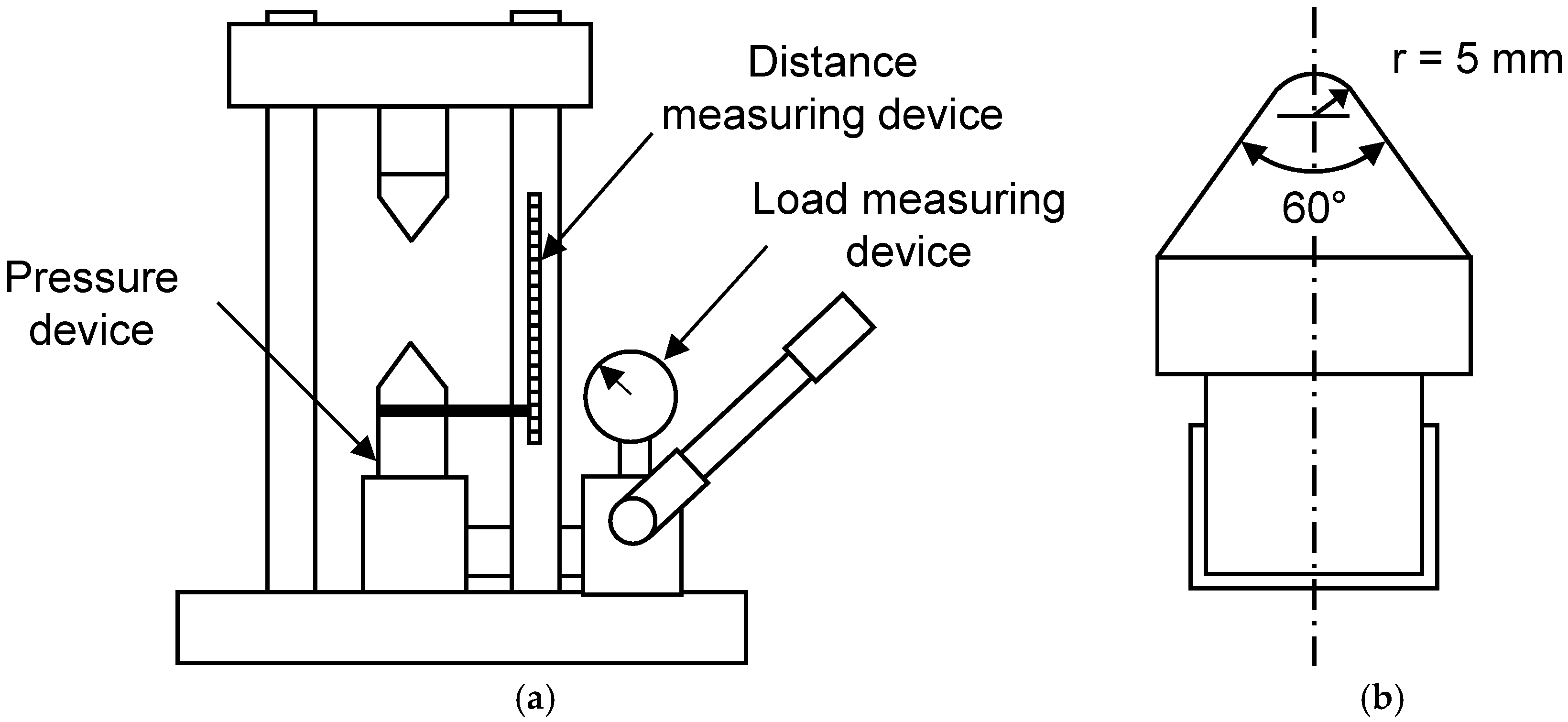
The point load tests were developed to measure the strength of the rock without manufacturing specimens. The testing device for the point load test is composed of a pressure device, load measuring device, and distance measuring device.
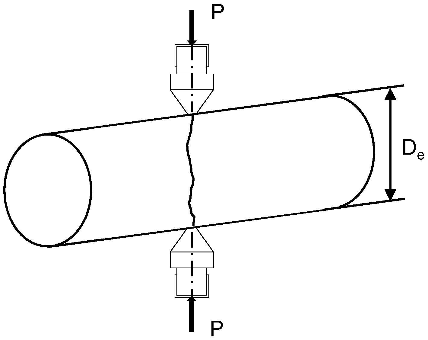
Figure 2 illustrates the schematic testing devices for point load tests. The failure load (
P) can be obtained by point loading using the pointed devices as shown in
Figure 3. In this study, the testing cores were near 50 mm in diameter, similar to NX core size. The point load tests can determine the corrected point load strength index (
Is(50)). The point load strength index (
Is(50)) is determined as follows:
where
Is(50) is the point load strength index,
P is the failure load (=pressure
piston area),
De is the equivalent core diameter.
Bieniawsky [
8] and Broch and Franklin [
7] proposed the relationship between the uniaxial compressive strength (UCS) and the point load strength. The uniaxial compressive strength can be calculated using the point load strength as follows:
where
σc is the uniaxial compressive strength (MPa), and
K is the conversion factor (
K = 24 for NX size).
3.3. Slake Durability Tests
The slaking effect is defined as a failure due to the decrease of bonding force among the particles caused by the repeating dryness and wetness of rock mass. When the clayey sedimentary rock or volcanic rock are exposed to the environment, the slaking effect of rock mass may occur frequently. In this study, the slake durability test is conducted according to ISRM [
9], intending to evaluate the resistance offered by a rock sample to weakness and deterioration after being subjected to drying and wetting.
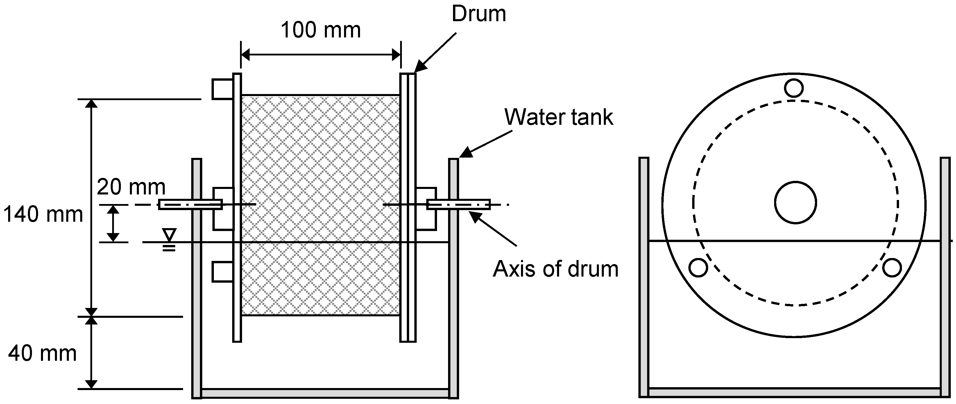
Figure 4 illustrates the front and side view of testing devices for slake durability tests. As shown in
Figure 4, the testing device for the slake durability test is composed of drums, a water tank, and rotating systems. The drum should be clean and dried for the sample to have a constant weight at a temperature of 105 °C. Also, the oven should have a capacity of maintaining a temperature of 105 °C for at least 12 h. The detailed procedures of the slake durability test are as follows.
- (1)
Ten rock masses which have a mass of 40~60 g are placed in the drums, and weight (A) of the drum and sample is measured.
- (2)
The lid is fitted with the drum and the drum is fixed in the trough and the motor. The trough is filled with slaking fluid, which usually has a temperature of 20 °C.
- (3)
The drums are rotated in a velocity of 20 rpm for 10 min, indicating that one cycle takes 10 min. The drum is removed from the trough and the lid is removed from the drum.
- (4)
The drum plus remaining sample is dried at a temperature of 105 °C. The weight (B) of the drum plus remaining sample is measured.
- (5)
Steps (2)–(4) are repeated and the weight (C) of the drum plus remaining sample is measured.
- (6)
The drum is cleaned and its weight (D) is measured.
The slaking durability index can be defined as the ratio of the weight of remaining rock to the weight of original rock. The 1st and 2nd cycle slake durability index can be obtained as follows:
Franklin and Chandra [
10] and Gamble [
11] reported that the 2nd slake durability index is usually used, as shown in
Table 3 and
Table 4. On the other hand, Taylor [
12] stated that the 3rd slake durability index could clearly distinguish between durable rock and nondurable rock. Therefore, the slake durability tests are performed by 4 cycles in this study, to investigate the dramatic change of weight of rock mass due to slake effects.
4. Proposed Rock Mass Classifications and Tunnel Support System in Unconsolidated Sedimentary Rock
4.1. Characterizations of Unconsolidated Sedimentary Rock
4.1.1. Results of TCR and RQD Tests
The core drillings in all sections, including the section of limestone and unconsolidated sedimentary rocks, were conducted to mainly investigate the characteristics of unconsolidated sedimentary rocks. TCR and RQD were measured on 10 cases for unconsolidated sedimentary rocks and 11 cases for limestone using the sample, respectively.
Table 5 summarizes the results of TCR and RQD. Based on the results of the core drilling, the average TCR and RQD of the limestone were 83.2% and 14.2%, respectively. The average TCR and RQD were 65.1% and 3.5%, respectively, for unconsolidated sedimentary rocks. The TCR of 65.1% means that the cementation of rock was good, because the rock joints for unconsolidated sedimentary rocks are not relatively developed due to the characteristics of matrix. However, RQD of 3.5% indicated ‘very poor’ rock quality according to
Table 2. Therefore, the RQD systems are meaningful approaches to classify typical rock mass having rock joints, whereas the RQD systems are unsuitable to the application of unconsolidated sedimentary rocks.
4.1.2. Results of Point Load Tests
For the unconsolidated sedimentary rocks, it is hard to create the specimen for uniaxial compressive tests. Thus, the point load tests were performed to predict UCS. The core sizes for tests were NX sizes (core diameter = 54 mm).
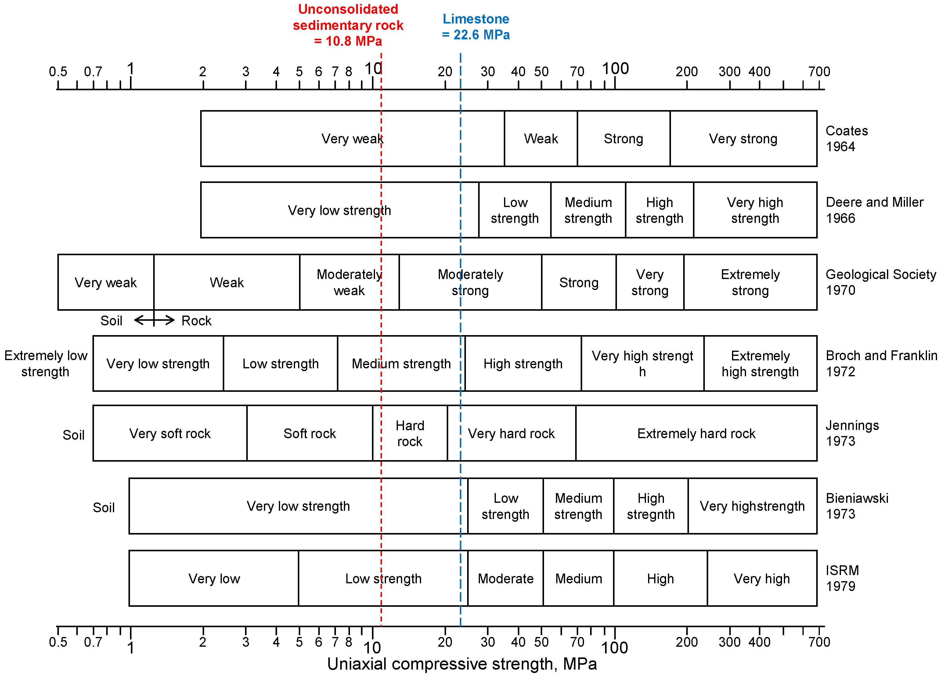
The point load tests were performed on 15 cases for unconsolidated sedimentary rocks and 8 cases for limestone. The average UCSs for unconsolidated sedimentary rocks and limestone were 10.8 MPa and 22.6 MPa, respectively. The test results in this study compared with the various rock classifications based on the UCS, which was reported by Bieniawski [
13].
Figure 5 shows the comparison of rock classification based on the UCS. In
Figure 5, the unconsolidated sedimentary rock could be classified into ‘very weak rock’ ~ ‘moderately weak’, excepting the rock classification by Jennings. For the limestone, it could be classified into ‘very weak rock’ ~ ‘very hard rock’. Based on test results, it is found that the measured UCS for unconsolidated sedimentary rocks were larger than the predicted UCS, whereas UCS for limestone were smaller than UCS for typical limestone. The results of the point load tests are summarized in
Table 6.
4.1.3. Results of Slake Durability Tests
The slake durability tests were performed to measure the slake durability index (
Id). The 22 cases for unconsolidated sedimentary rocks and 16 cases for lime stones were conducted.
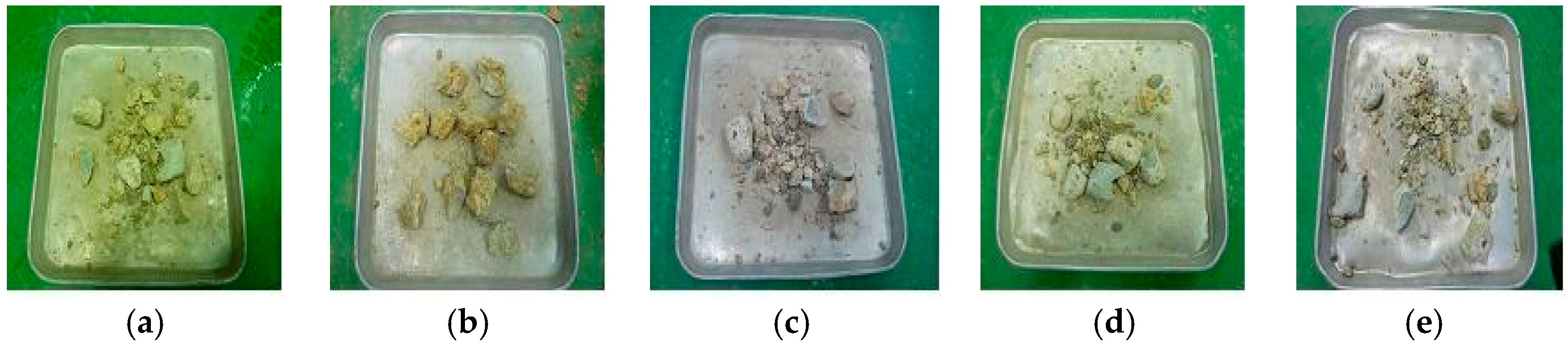
Figure 6 shows the sample of rock samples from different cycles. The results of slake durability tests are summarized in
Table 7. For the unconsolidated sedimentary rocks, the average slake durability indexes with cycles
Id1,
Id2,
Id3 and
Id4, were 88.5, 78.2, 71.8 and 67.9, respectively. For the limestone, the average slake durability indexes with cycles
Id1,
Id2,
Id3 and
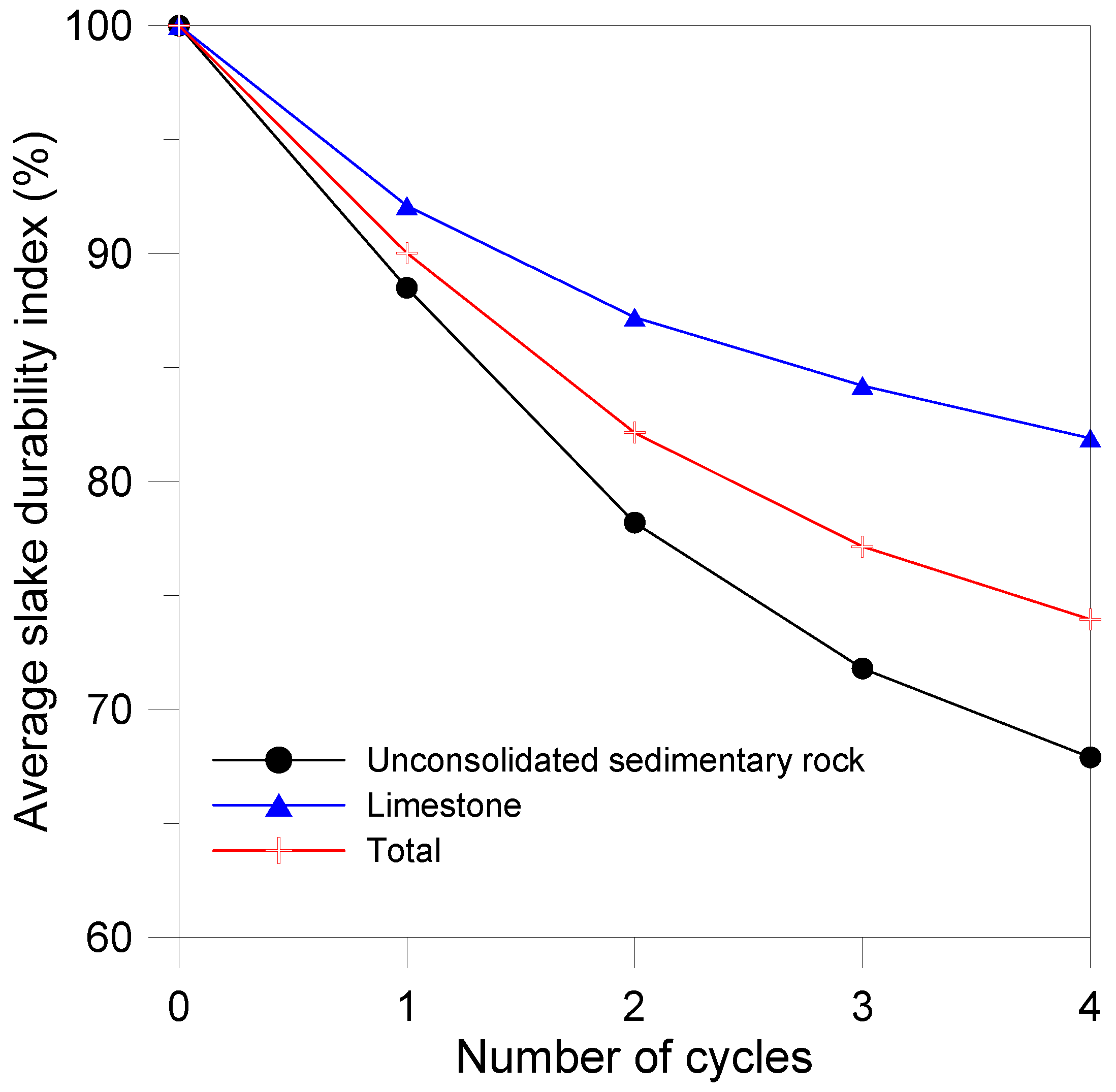
Id4, were 92.1, 87.2, 84.2 and 81.9, respectively. It is found that the slake durability indexes for unconsolidated sedimentary rocks are smaller than those for the limestone. Hence, this means that the limestones have more resistance to deterioration after being subjected to drying and wetting, than unconsolidated sedimentary rocks. Thus, rock classifications for unconsolidated sedimentary rocks should take into account the slake durability index. Also,
Figure 7 illustrates the average slake durability index with cycles. In
Figure 7, it is shown the resistance against weakness and deterioration for unconsolidated sedimentary rocks was weaker than that for limestone.
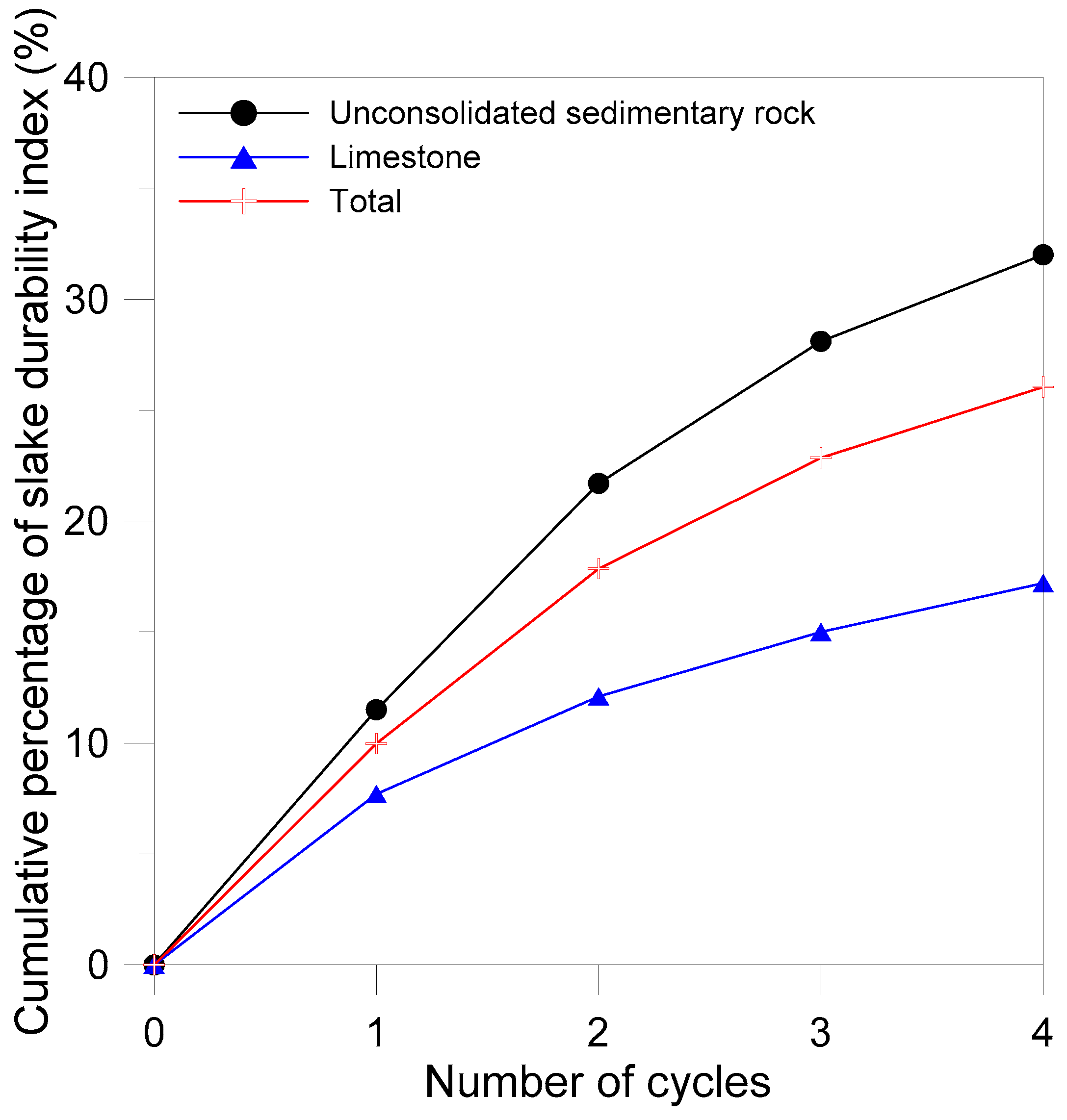
To investigate the convergence of the slake durability index with cycles, the differences between cycles are summarized in
Table 8. In addition,
Figure 8 shows the cumulative percentage of slake durability index with cycles. As shown in
Figure 8, as the number of cycles increased, the relative differences decreased. As mentioned above, Franklin and Chandra [
10] and Gamble [
11] reported that the 2nd slake durability index is generally used. Especially, Franklin and Chandra [
10] reported that 2nd cycle slake durability index should be from 0 to 10 times greater than the 1st cycle slake durability index. In
Table 8, in case of unconsolidated sedimentary rocks, the average values of ‘Initial −
Id1’ and ‘
Id1 −
Id2’ are 11.5 and 10.2, respectively. However, the average value of ‘
Id2 −
Id3’ is 6.4. It means that the 2nd slake durability index for unconsolidated sedimentary rocks may not be converged, because the value of ‘
Id1 −
Id2’ is greater than 10. Therefore, as shown by measured results, it is reasonable for the 3rd slake durability index to be applied to the rock mass classification for unconsolidated sedimentary rocks, because the value of ‘
Id2 −
Id3’ is between 0 and 10 according to Franklin and Chandra [
10], demonstrating the 3rd slake durability index reaches the convergence.
4.2. Proposed Rock Mass Classifications
The Rock Mass Rating (RMR) and the Q-system are commonly used for rock mass classifications for typical tunnels [
4]. However, these systems have 70% more evaluation criteria, considering the rock joints. RQD, which is a part of RMR and Q-system, is also meaningful for rock joints. Based on the results of TCR and RQD, the cementation of unconsolidated sedimentary rocks was good, because of the average TCR of 65.1%; however, the rock quality for that was ‘very poor’ due to RQD of 3.5%. The rock joints for unconsolidated sedimentary rocks are not relatively developed due to the characteristics of matrix. Thus, the RQD system cannot be applied to the rock classification for unconsolidated sedimentary rocks because of the weakness of rock joints.
In this study, the UCS—which can be quantitatively obtained by point load tests—and the slake durability index are chosen to be the important factors in evaluating rock mass classification for evaluation of unconsolidated sedimentary rocks. Additionally, the factors which can be detected at tunnel surfaces under constructions are selected. Based on the results of various tests, the rock mass classifications for unconsolidated sedimentary rocks are proposed. The proposed rock mass classifications can be classified into three classes from P-1 to P-3.
In the case of UCS, the average UCS of unconsolidated sedimentary rock was 10.8 MPa. Based on the results of point load tests, it is found that the measured UCS for unconsolidated sedimentary rocks were larger than the predicted UCS. According to ISRM, the UCS of ‘low strength rock (weak rock)’ was 5 MPa or more; thus, the measured UCS for unconsolidated sedimentary rocks could be classified into ‘low strength rock (weak rock)’. Therefore, the boundary strength between ‘cementation-good (P-1)’ and ‘cementation-fair (P-2)’ grade are chosen as 5 MPa, indicating the boundary of weak rock. Also, the UCS of ‘very low strength’ was between 1 and 5 MPa according to ISRM, therefore the boundary strength between ‘cementation-fair (P-2)’ and ‘cementation-poor (P-3)’ grade was chosen as 1 MPa, indicating the boundary of weathered soil and rocks. In addition, the wetting conditions caused by water are selected as factors which can be detected at tunnel surface under constructions. The wetting conditions are classified into three conditions, such as ‘complete drying or with moisture’, ‘wetting’, and ‘water drops fall’.
For the slake durability index, it is reasonable that the 3rd slake durability index is applied to the rock mass classification for unconsolidated sedimentary rocks, as mentioned above. The measured average Id2 and Id3 of unconsolidated sedimentary rock was 61.2 and 57.6%, respectively. Therefore, the slake durability index at 3rd cycle of approximately 60% is selected as the factor of evaluating cementation.
In this study, the rock mass classifications for unconsolidated sedimentary rocks are proposed through the comprehensive analyses of various experimental tests, and summarized in
Table 9.
4.3. Proposed Reinforcment Types
If the rock mass classification and tunnel support system for unconsolidated sedimentary rocks are divided into many grades in design stages, it is hard to determine the rock quality and to choose the appropriate tunnel support system for unconsolidated sedimentary rocks. Thus, in this study, the tunnel support system for unconsolidated sedimentary rocks is proposed according to the rock mass classifications. The proposed tunnel support system can be classified into three grades considering the safety and constructability of the tunnel.
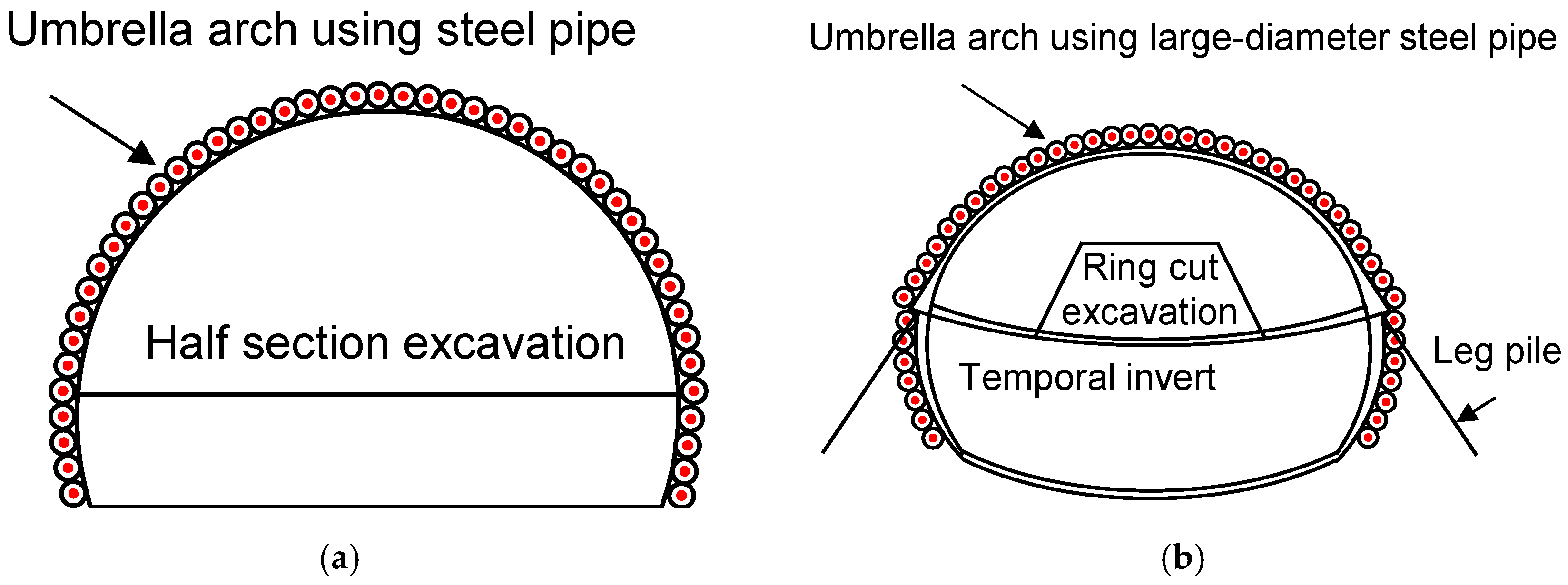
Table 10 and
Figure 9 show the proposed tunnel support system for unconsolidated sedimentary rocks. For rock of good quality—having a UCS of 5 MPa or more and a slake durability index at 3rd cycle (
Id3) of 60% or more; the P-1 pattern—it is proposed that reinforcement is added to the pattern of a typical section. In particular, the umbrella arch reinforcement method is applied instead of the rock bolt, because it is expected that the pullout capacity of rock bolt installed in unconsolidated sedimentary rocks may not satisfy the criteria. In addition, the P-2 and P-3 patterns for the rock of fair and poor quality are proposed, respectively.
To verify the adequacy of the proposed tunnel support system for unconsolidated sedimentary rocks, two-dimensional finite element analyses are performed for the proposed pattern of the tunnel support system. The MIDAS-GTS [
14] commercial program was employed to simulate the behavior of the tunnel. The overall dimensions comprised a width of 4 times the tunnel width (
D) and a height of 6 times the tunnel height (
H). The unconsolidated sedimentary rocks were modeled as linearly elastic/perfectly plastic materials with the Mohr-Coulomb failure criterion.
Table 11 and
Table 12 summarize the load distribution and rock properties for numerical analyses, respectively.
The results of numerical analyses with proposed tunnel support systems are summarized in
Table 13. From the present analyses, the maximum displacement and bending stress of shotcrete—when the P-3 for tunnel support system is applied—were the largest among the analysis cases. However, the displacement and bending stress of Case 1 cannot influence the safety of the tunnel. Hence, it is found that the proposed tunnel support systems can ensure the safety of the tunnel.
5. Deformation Behavior of Unconsolidated Sedimentary Rocks
The objective of tunnel convergence measurement is to investigate the mechanical behavior of tunnel support and surrounding soil due to excavation; the safety of the tunnel should also be checked. In this study, the tunnel convergence measurement is conducted to verify the adequacy of the proposed tunnel support system and to investigate the long-term deformation behavior of the tunnel.
After the excavation, the tunnel convergence measurements from 52 cases and 21 cases in sections of unconsolidated sedimentary rocks and limestones are analyzed, respectively.
Table 14 and
Table 15 summarize the convergence in unconsolidated sedimentary rocks and limestones, respectively.
The maintenance criteria for convergence of tunnels are summarized in
Table 16. According to these criteria, there are no cases in which the measured maximum convergence exceeds the criteria. In addition, the measured convergence for unconsolidated sedimentary rocks and limestones are summarized in
Table 17. As shown in this table, the average velocity of displacement for unconsolidated sedimentary rocks and limestones are 0.068 mm/day and 0.048 mm/day, respectively. It is shown that the average velocity of displacement for unconsolidated sedimentary rocks is about 40% faster than that for limestones, and satisfy the criteria according to
Table 16.
The duration for convergence is based on the moment when the displacement does not increase any more (7 days). The duration for convergence for unconsolidated sedimentary rocks and limestones were 119 days and 49 days, respectively, and it was confirmed that the duration for convergence for unconsolidated sedimentary rocks requires more than 2 times that of limestones. The average maximum displacement was also measured as 8.15 mm for the unconsolidated sedimentary rock and 2.37 mm for the limestone.
As a result, the velocity of displacement for unconsolidated sedimentary rocks is similar to that of limestones, whereas the duration for convergence of unconsolidated sedimentary rocks is larger than that of limestones. However, the proposed tunnel support system is appropriate for the unconsolidated sedimentary rocks, since the convergence factors, such as the maximum displacement and velocity of displacement, satisfy the criteria.
6. Conclusions
The main objective of this study is to investigate and present the characteristics of unconsolidated sedimentary rock using the point load tests and slake durability tests. In addition, the appropriate rock mass classification and tunnel support system for the unconsolidated sedimentary rock tunnel are proposed based on the results of experimental tests. The proposed rock mass classification and tunnel support system are validated through comparison against results from measuring the convergence of a tunnel under the construction. The following conclusions could be drawn from the present study:
This paper provides new valuable field data and a comprehensive approach to the determination of rock mass classification and tunnel support systems for tunnels in unconsolidated sedimentary rocks.
The 2nd slake durability index is generally used for the rock mass classification [
10,
11]. However, based on the results of slake durability tests, it is reasonable that the 3rd slake durability index is applied to the rock mass classification for unconsolidated sedimentary rocks, since the increment between 2nd cycle and 3rd cycle was larger than that between 3rd cycle and 4th cycle, demonstrating that the 3rd slake durability index reaches the convergence.
The UCS, which can be quantitatively obtained by the point load tests, and the slake durability index are chosen to be important factors in evaluating rock mass classification for unconsolidated sedimentary rocks. Based on the results of various tests, the rock mass classifications for unconsolidated sedimentary rocks are proposed. The proposed rock mass classifications can be classified into three classes, from P-1 to P-3.
The tunnel support system for unconsolidated sedimentary rocks is proposed according to the proposed rock mass classification. To verify the adequacy of the proposed tunnel support system for unconsolidated sedimentary rocks, two-dimensional finite element analyses are performed for the proposed pattern of the tunnel support system. Based on the numerical analysis, it is found that the proposed tunnel support systems are ensured to the safety of tunnel.
The tunnel convergence from 52 cases and 21 cases in sections of unconsolidated sedimentary rocks and limestones are measured, respectively. As a result, the velocity of displacement for unconsolidated sedimentary rocks is similar to that of limestones, whereas the duration for convergence of unconsolidated sedimentary rocks is larger than that of limestones. However, the proposed tunnel support system is appropriate for unconsolidated sedimentary rocks, since the convergence factors, such as the maximum displacement and velocity of displacement, satisfy the criteria.


