Autonomous Mobile Scanning Systems for the Digitization of Buildings: A Review


3D Visual Computing and Robotics Laboratory, Universidad de Castilla-La Mancha, Paseo de la Universidad, 4, 13071 Ciudad Real, Spain
*
Author to whom correspondence should be addressed.
Remote Sens. 2019, 11(3), 306; https://doi.org/10.3390/rs11030306
Submission received: 28 November 2018
/
Revised: 28 January 2019
/
Accepted: 31 January 2019
/
Published: 2 February 2019
(This article belongs to the Special Issue Mobile Laser Scanning)
Abstract
:Mobile scanning systems are being used more and more frequently in industry, construction, and artificial intelligent applications. More particularly, autonomous scanning plays an essential role in the field of the automatic creation of 3D models of building. This paper presents a critical review of current autonomous scanning systems, discussing essential aspects that determine the efficiency and applicability of a scanning system in real environments. Some important issues, such as data redundancy, occlusion, initial assumptions, the complexity of the scanned scene, and autonomy, are analysed in the first part of the document, while the second part discusses other important aspects, such as pre-processing, time requirements, evaluation, and opening detection. A set of representative autonomous systems is then chosen for comparison, and the aforementioned characteristics are shown together in several illustrative tables. Principal gaps, limitations, and future developments are presented in the last section. The paper provides the reader with a general view of the world of autonomous scanning and emphasizes the difficulties and challenges that new autonomous platforms should tackle in the future.
1. Introduction
The creation of 3D models of buildings from 3D data is still a semi-manual work. Of particular relevance in this respect is the fact that, during the extraction of as-is models, an operator must manually take and process millions of datum (mainly 3D points), which entails time and errors in the model obtained.
However, the era of the automatic creation of what are denominated as Building Information Models (BIM) has brought about new systems, procedures, and algorithms that are able to collect and process a huge amount of data efficiently without the help of humans. In the last few years, the fields of artificial intelligence and robotics have, therefore, burst into the automatic BIM world.
Very few reviews concerning autonomous 3D scanning in construction can be found in literature to date. Representative surveys related to this research field can be found in References [1,2,3]. Lehtola et al. [1] present a review of the latest commanded mobile scanning techniques, focusing on aspects related to the quality of the point cloud and the metrics used. The survey also presents essential aspects that determine the goodness and applicability of the existing mobile autonomous 3D scanning systems and discusses the current limitations and gaps in this research field. Kostavelis et al. [2] present a survey regarding semantic mapping obtained from mobile robots. The paper categorizes the existing methods and shows the current applications implemented in mobile robots. A discussion concerning the sensors and strategies utilised in the construction of metric maps of the inside of buildings is carried out and the authors conclude their paper with a discussion of open issues. In Reference [3], the survey is focused on the inspection of structures, such as bridges, turbines, ships, and others, by using robotic systems. The paper mainly addresses coverage path planning and 3D model reconstruction. It also includes detailed information on viewpoint generation, coverage path generation, evaluation, and applications for coverage path planning, sensors, algorithms, and properties for the 3D reconstruction works surveyed.
This paper provides a review from a different point of view focused on autonomous scanning in construction. This survey is organised as follows. Section 2 introduces the building scanning concept by showing representative autonomous platforms. Section 3 establishes the context in which this survey is framed. Current key issues and problems in the field of autonomous 3D scanning (data acquisition) of buildings are analysed in Section 4. Section 5 makes a comparison, from several points of view, between the most important autonomous scanning systems in the construction context (i.e., buildings and facilities). Properties and characteristics are first discussed and are, later, gathered together in several comparative Tables. Weaknesses and strengths are dealt with in Section 6. Finally, Section 7 presents the principal improvements, challenges, and future projects.
2. Autonomous Scanning Platforms
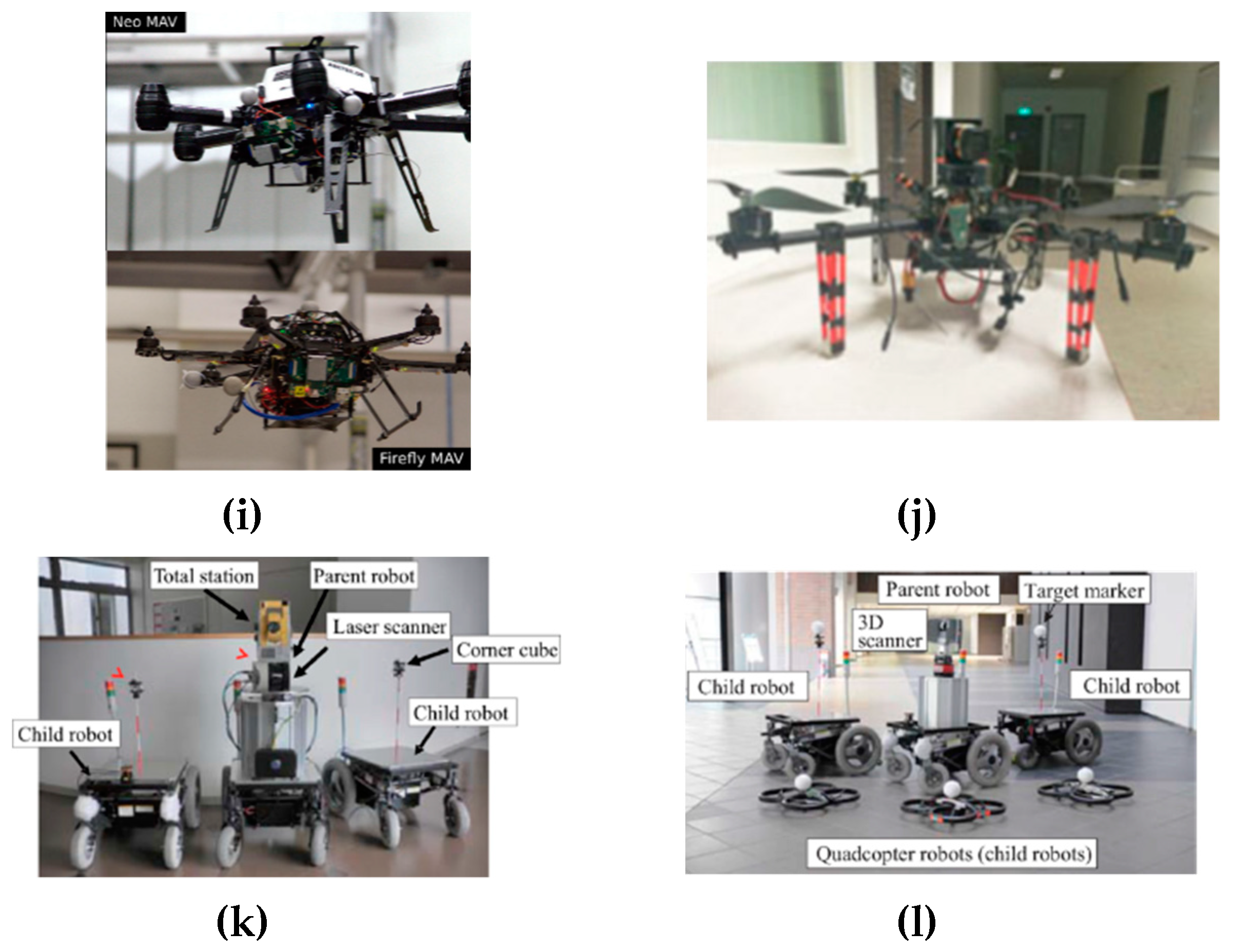
Completely autonomous systems are those that are able to perform navigation, 3D data acquisition, and 3D data processing, without any initial knowledge of the scene and without human interaction. This degree of autonomy is attained thanks to efficient next best view (NBV) algorithms, which are adapted to each particular mobile platform. Representative examples of mobile scanning robots are illustrated in Figure 1.
The first autonomous platforms appeared in the period 1995–2010. Sequeira et al. [4] present a simple autonomous robot that partially digitalizes a single room with a time-of-flight laser range finder. A pan-tilt unit is used to collect a range image with 140 by 140 samples, covering a field of view of 60° by 60°. Surmann et al. develop Ariadne robot [5], a mobile platform with a 3D laser range finder that was capable of digitalizing large indoor environments. The Rosete platform is presented by Strand et al. in Reference [6]. In order to overcome the small viewing cone of the earlier commercial 3D scanners, they introduce a rotating laser scanner mounted on a mobile platform and successfully scans simple indoor scenarios. ATRV-2 AVENUE [7] is designed to acquire data from large-scale outdoors sites. It consists of a laser-scanner-equipped robot that assumes a previous rough localization (2D-map), which is necessary to calculate the route with a minimal set of views. Therefore, although the system has a high degree of autonomy, it requires essential information about the scene.
The platform of Blodow et al. [8] autonomously explores indoor environments and provides a semantic map obtained from colored point clouds. The robot, which is denominated as the “PR2” robot, has a tilting laser scanner and a color camera, which is panned and tilted to overcome the problem of its short field of view. This technique is applied to the drawers and doors. The same robot is used in Reference [9], but now to analyze the performance of a next best view algorithm in small and cluttered environments. In this case, the scene consists of a table top with different objects, which are sensed and recognized for robot interaction tasks. Charrow et al. [10] carry out 3D mapping of indoor environments using a ground robot equipped with a 2D laser range finder and a RGB-D camera. A single experiment is developed on a set of connected corridors and without occlusion. Iocchi et al. [11] obtain 3D maps of buildings by integrating a 2D laser, stereo-vision, and IMU on a mobile robot. Bormann et al. [12] present the platform Irma3D, a robotic platform that automatically creates 3D thermal models of indoor environments. The mobile platform is equipped with a 3D laser scanner, a thermal camera and an RGB camera. A 2D laser scanner is used for obstacle avoidance.
In the last few years, micro aerial vehicles (MAV) have also been used as autonomous platforms that extract 3D information from indoor and outdoor scenes. Bircher et al. [15] proposed a new path-planning algorithm for the autonomous exploration of an unknown volume using a firefly hexacopter and a stereo camera. The experiment took place in a single room. A similar UAV platform with two configurations is presented in Reference [16]. Heng et al. [18] present an algorithm for simultaneous exploration and coverage with an assumed data acquisition system composed of an MAV equipped with a forward-looking depth-sensing camera. The system is simulated in an office-like environment.
In another context, the platform of Rusu et al. [19] acquires 3D maps of kitchens with the aim of interacting with recognized objects. The robot enters the room and sweeps the scene with a laser mounted on its end effector. The output is a coarse 3D model composed of cuboids and planes that represent relevant objects, such as containers or tables.
The most recent proposals are those of References [13,14,17]. Kurazume et al. [17] have proposed an innovative cooperative multiple robot system that scan indoors and outdoors. The system is composed of a mobile robot equipped with an on-board 3D laser scanner (the parent robot) and several child robots, including terrestrial robots and quadcopters. The parent robot obtains 3D data and generates a large-scale 3D model, whereas the child robots implement a precise localization technique. The system does not have any knowledge of the environment and works autonomously in complex scenarios. Kim et al. [14] introduce a robotic platform with a hybrid laser scanning system composed of five 2D laser scanners and a digital single-lens reflex (DSLR) camera. The robot classifies the next positions obtained after analyzing the visible area of a previously built 2D map into three diffuse categories and moves to the best next position. By following this method, the system can move autonomously in corridors, but the scanning completeness is not guaranteed. Finally, the autonomous robotic platform MoPAD [13], composed of a 3D laser scanner and a RGB camera, is able to generate detailed 3D models of the indoors of buildings. This platform has been tested in more complex scenes with clutter and occlusion.
Table 1 presents a summary of a set of representative autonomous mobile scanning systems, including the environment tested, the technology, and the type of degree of autonomy.
3. Context of the Review in the Process of the Creation of As-Is Models
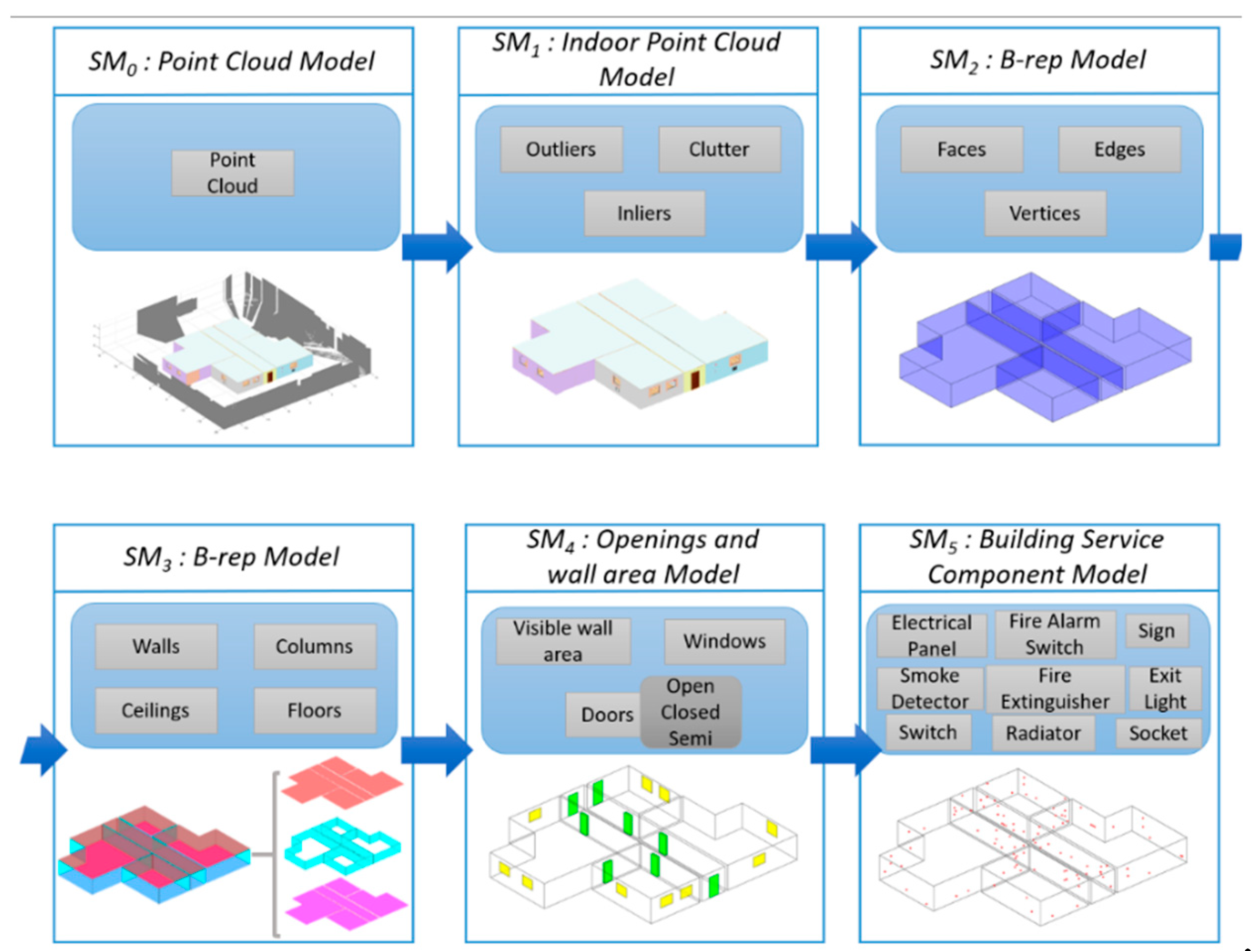
Some of the scanning systems referenced collect partial data of the environment [4] or do not generate a formal geometric model of the scene as seen in References [6,10,12,14,17]. However, our interest lies in generating automatically geometric semantic models of buildings. The degree of automation varies from the simple automatic acquisition of data (i.e., coordinates of 3D points, color, and temperature, etc.) carried out by mobile robots/platforms, to the automatic detection and positioning of small components of the building (e.g., signs or sockets on walls). In general, the modeling tasks are carried out at five levels, each of which provides a particular semantic model. Figure 2 shows these levels and the outputs at each of them.
This paper discusses the methodologies and processes followed to accumulate dense 3D information of the scene with the objective of creating a realistic 3D model of a building. Of all these levels, this survey covers only the first and the second level, which are directly related to the acquisition of 3D data.
The first level (see Figure 2) concerns the automatic data acquisition of the building. The semantic model at this level is, therefore, a mere collection of unconnected 3D data of the visible scene (3D data are coordinates and, sometimes, and color). Thanks to the scan planning and the next best scan algorithms, the autonomous moving platforms collect sufficient information and roughly represent the inside of References [5,6,10,11,12], or outside [7] of the buildings.
At the second level, a simplified geometric model of the building is obtained. At this level, the model is composed of primary features, such as vertices, edges, and faces. This representation is commonly implemented by using a graph-structure, which relates these geometric primitives, all of which form a B-rep representation [7,20,21,22]. This simple model does not yet contain valuable information from a semantic point of view.
The first and second levels are sometimes mixed into a single level at which the scanner simultaneously collects the data from a mobile platform and generates a primitive polyhedral model of the indoor scene scanned in References [8,11,13].
Higher levels concern the recognition of essential structural elements (SE), the recognition and labeling of essential parts of these structural elements and the recognition of small building service components. None of these levels, which concern 3D data processing and modeling, are within the scope of this review.
In the following sections, we analyze current key issues and problems in the field of the autonomous 3D scanning of buildings and make a comparison among the most important systems in the construction context.
4. Open Issues
Autonomous scanning appeared in the late 1990s as a new and challenging topic and became more and more important as the functionality and accuracy of sensors improved.
While some scanning platforms are currently able to autonomously scan specific environments and simple scenarios, there are still a number of underlying questions in this research field, which are rarely debated in papers. These open issues are related to the achievements and limitations of the autonomous scanning methods. As will be shown throughout this paper, the current systems still have gaps and serious weaknesses that need to be addressed in order to create autonomous systems that are able to work in realistic environments. A critical discussion of this is presented in the following subsections.
4.1. Utility and Redundancy of the Data
3D scanning entails collecting data from the scene, but the question is: Which of the collected data are and are not necessary to develop a further application? Or otherwise, is there a particular strategy that considers the utility (i.e., useful or useless) of the data before the scan is carried out?
While the final goal of some approaches is to create a 3D model of a building, the objective of their scanning stage is to accumulate as much data of the visible area as possible [14]. Since the goal is simply to scan everything inside (or outside) the building, these approaches do not deal with the utility of the data collected in References [5,9,12,23]. Redundancy and cluttering are thus ignored by these brute-force scanning techniques. As a consequence of this, a huge amount of data has to be processed after several scans, with the sole aim of recognizing furniture [8], or extracting frontiers. 3D mapping in References [7,9,10,12,24,19], and robot localization/navigation [10,25,26] and digitization [5,27] are research lines in which the data redundancy problem is not considered in the data acquisition stage. However, some redundancy in the collected data can also be useful, for instance to increase robustness or to increase the probability of completeness of the model.
In the case of the extraction of a model of the building, most techniques have to manage a huge amount of irrelevant 3D data, which do not correspond to the structural components of the building, but rather to other objects inside the scene (i.e., furniture and clutter) [6,11,28]. These methods are inefficient because a part of the point cloud is unimportant as regards creating the 3D model. For example, if the goal of the process is to detect openings within a room, the data pertaining to the furniture is unimportant information.
In contrast with these methods, there are few that focus the scanning towards collecting ‘useful’ 3D data of the scene. This means that if the objective is to create a 3D model of the inside of the building, the scan planning algorithm is focused on collecting data from the structural elements (SE), which are essentially the floor, walls, columns, and ceiling [13]. In this case, the next best scanner position is based on the already sensed and recognized parts of the building structure. Such algorithms consequently reduce the amount of data and the time, and also alleviate the algorithmic complexity in further processes.
In summary, optimizing the choice of the regions of the scene to be sensed is an unexplored issue that could be addressed in the future. The alternative of interactive scan planning strategies, therefore, makes sense in this context. A hybrid human-computer approach entails a semi-automated optimization of the scanning process, in which the knowledge of the geometry and heuristics can help the user to decide the best scan planning and achieve a high-quality model of the scene. This strategy has been successfully carried out during the large-scale recording of heritage [29].
4.2. The Complexity of the Scene
Among other aspects, a complex scene has a high component of occlusion and clutter, such as a lounge in an inhabited building. Complexity also implies irregular geometry, such as non-regular rooms (i.e., concave/convex storey rooms), which are connected through openings (mainly doors).
4.2.1. Geometry
With regard to the interiors of buildings, some systems are constrained to the scanning of corridors [10], which are very simple shapes. Most works deal with scenes composed of a corridor to which several rooms are connected [5,6,11,12,24,25,26,27,30]. In some cases, the mobile scanning system moves along the corridor, enters the room in order to take 3D data, leaves the room, and goes back to the corridor [5,12]. These systems are prepared to only work in such topologies.
Many of the systems work in rectangular rooms [5,6,12,15,18,24,25,27,30], and a few in free-shape interiors [11]. Iocchi et al. [11] generated a multilevel 2D-map with which to generate not-necessarily orthogonal structural elements. Moreover, the system is able to manage the changes in the plane of the room with the help of an inertial measurement unit. Scenarios with more flexible shapes are used in Reference [26], but the goal here is not to build a 3D model of the scenario, but rather to navigate with the help of depth cameras. Approaches that work in free-shape scenarios, such as abandoned mines [31] with winding corridors, are usually hand-guided and are not, therefore, within the scope of this paper.
The reconstruction of concave rooms is not frequently dealt with. Jun et al. [32] proposes a method with which to cut the point cloud data with arbitrary plans and extract the convex parts. Nevertheless, some concave structures may not be detected. This method has been tested by humans that carry a 3D LIDAR. The system presented by Prieto et al. [13] is able to deal with convex and concave rooms connected by doors.
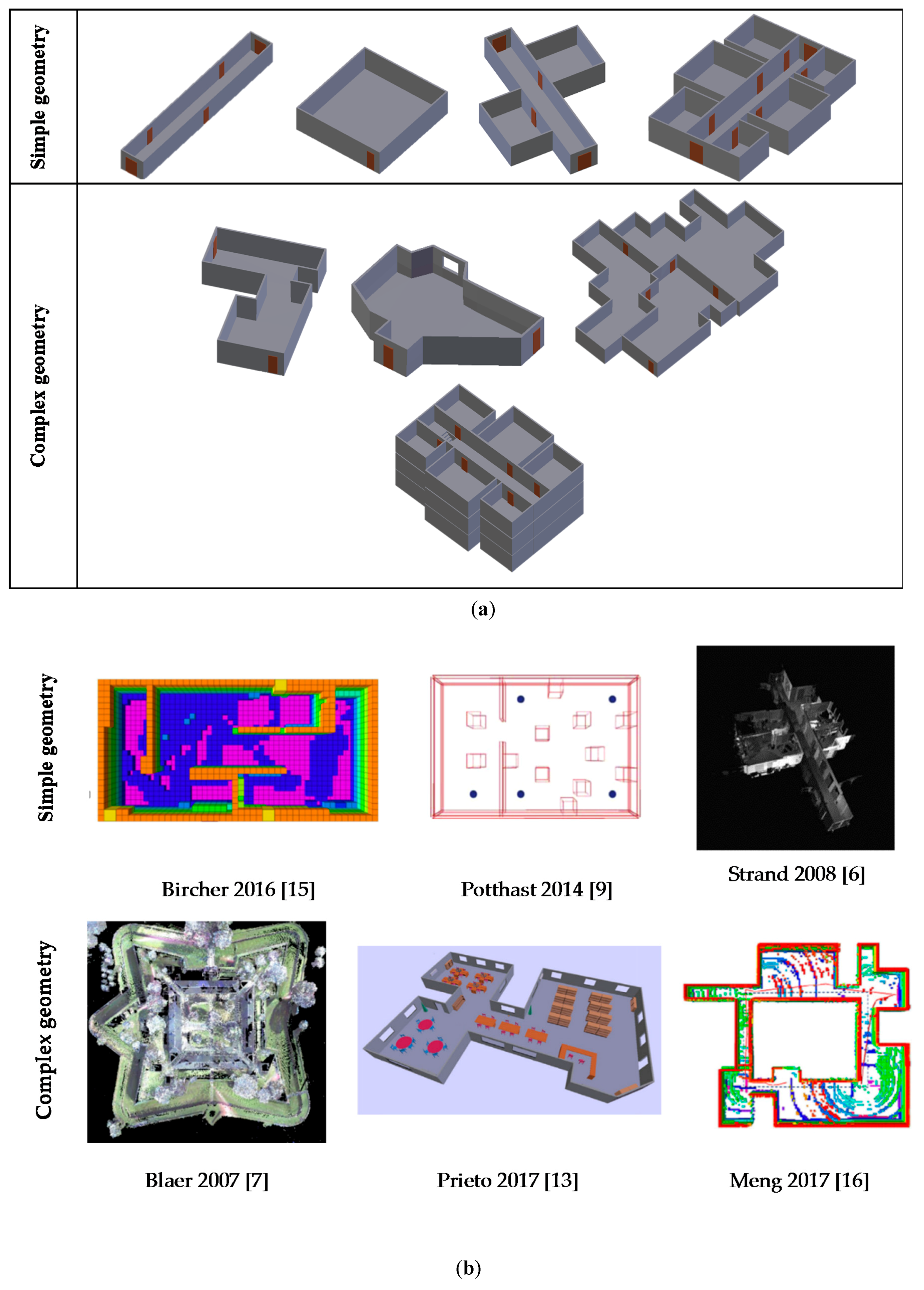
Few exterior-scanning techniques with robots can be found in literature. Good examples are those of Wolf et al. [33] and Blaer et al. [7]. Wolf et al. digitize buildings and obtain very simple 3D shape models, such as parallelepipeds, but the robot is commanded externally. Blaer et al. [7] present an automated data acquisition on large-scale outdoor sites, but they assume that a two-dimensional map of the region is known. Kim et al. [14] validate their method in both outdoor and indoor environments. Recent MAVs with on-board 3D sensors are applied to extract coarse models of the facades of building [15,16]. Figure 3a presents prototypes of simple and complex geometry of indoors, whereas Figure 3b shows scenes tested with the platforms referenced in Section 2.
Much work is required to automatically digitize more complex scenes. The autonomy of the current systems is limited to indoor scenes composed of a large single room or a wide corridor and a few rooms on a single storey. The autonomous scanning of a complete building composed of multiple storeys is one of the most important future challenges.
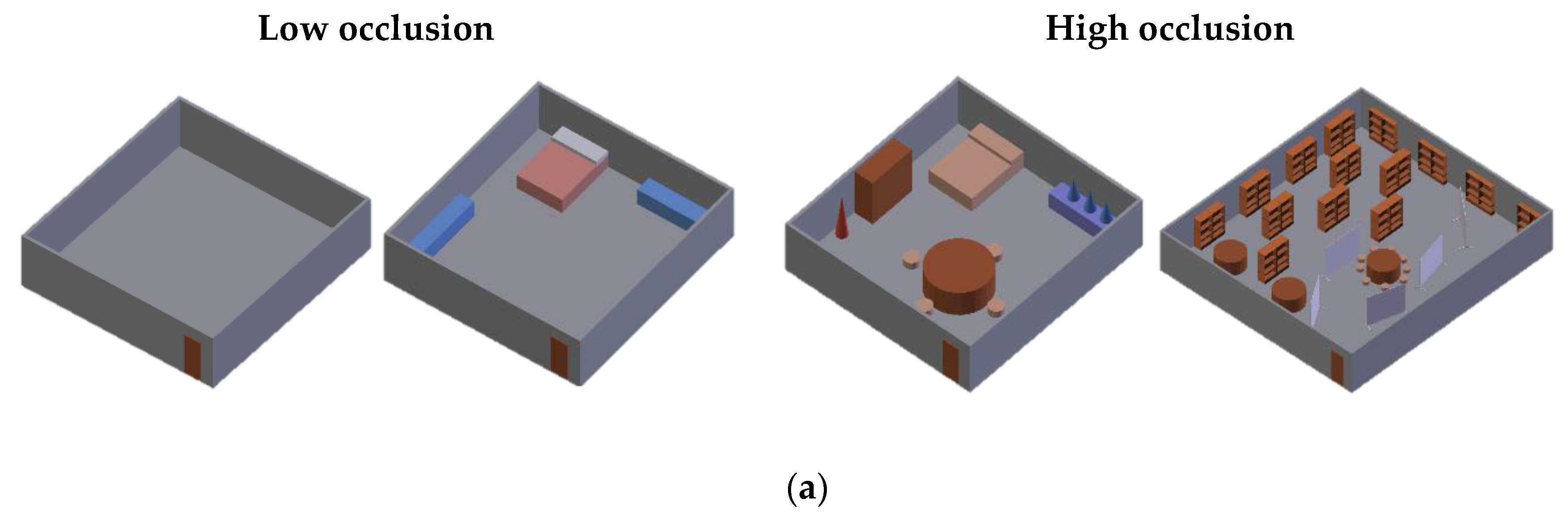
4.2.2. Occlusion and Clutter
In the building scanning field, occlusion is considered to be one of the principal sources of uncertainty. In order to avoid occlusions, the operators scan the environment from many different viewpoints and thus generate a fused point cloud. However, human scanning can be inefficient and time-consuming.
There are authors who explicitly do not refer to the occlusion problem [11]. Some approaches work only in empty scenarios or deal with little occlusion and clutter [5]. In these cases, the point cloud is easily processed and the navigation of the mobile system is also quite simple in interiors [10]. Other methods are tested by considering small obstacles in the scene [6,16,26]. In these scenes, the segmentation of points that belong to structural parts of the building are calculated by applying RANSAC [34], or other similar matching algorithms [35]. The next-best-position scan algorithms work perfectly in such a friendly framework and a single 3D model is easily obtained.
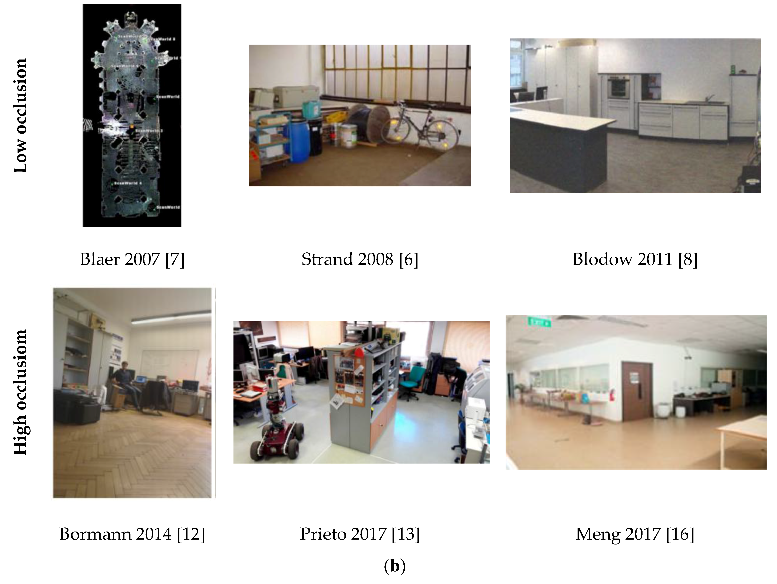
On the contrary, in inhabited scenes, a lot of objects, such as pieces of furniture, shelves, or even human beings, might occlude the essential structural parts of the building. In these cases, the lack of information entails the use of more robust and efficient NBV algorithms [12,13,30]. Some examples of works that deal with high levels of occlusions are those of [7,8,9,12,13]. In Reference [7], a church, with a particularly cluttered environment, which includes several chairs and tables, is scanned by using a particular NBV algorithm. Owing to the difficulty of the scene as regards autonomous navigation, the robot is manually guided along the narrow paths towards the next scanning position. Besides indoor scenes, this method also digitises outdoor scenes, e.g., large forts, which contain high levels of clutter and occlusion. Blodow et al. [8] propose an NBV algorithm for the digitization of kitchen environments. These scenes usually contain a high level of clutter and occlusion owing to the kitchen furniture and household appliances in them. Bormann et al. [12] propose an NBV algorithm that combines 2D and 3D planning. The 3D information is used to reduce the percentage of occlusion obtained from the 2D planning. The NBV algorithm proposed by Potthast et al. [9] is able to work in two different kinds of scenes: Small and cluttered environments (a table top with a large number of objects) and in large-scale office environments. The small environments contain a high level of clutter and occlusion, whereas the large-scale office environments are simple simulated scenes with little clutter. The method proposed by Prieto et al. [13] addresses the occlusion problem in the same planning algorithm. The experimentation presented is carried out in several scenarios with a high level of clutter and occlusion.
4.3. The Next Best Scan Position
One of the keys in automatic scanning with occlusion is that of a good selection of the next scanner position. The decision regarding the best next position should lead to the attainment of a complete, high-quality and non-redundant digitization process. This is known in literature as the Next Best View problem (NBV) [36], but in our context, this could be renamed as Next Best Scan (NBS).
Most autonomous methods use the current 2D map of the scene and estimate the next scan position on the basis of the future visibility of the scene, sometimes with low levels of occlusion [14]. Several of these techniques employ the frontier-based approach as a starting point [17,37]. However, 2D information is highly incomplete in terms of occlusion in a 3D world and frequently leads the system to erroneous or non-optimum positions. In addition, the next best position algorithm should take into account more important parameters regarding the accessibility and security of the mobile platform, along with its cost in terms of power.
3D information-based NBV algorithms are more efficient when exploring volumes and inspecting surfaces. Blaer et al. [7] propose a two stage-planning algorithm. In the first stage, a coarse model of the scene is obtained by making use of a 2D map, setting several random scanning locations on the map and selecting an optimal set of positions which covers the boundaries of the free space. In the second stage, the coarse model obtained is refined. A 3D NBV algorithm is executed in a voxel space with labels: unseen, seen-empty and seen-occupied. The position from which more boundary unseen voxels (unseen voxels adjacent to seen-empty voxels) are seen is then selected as the next best position. Surmann et al. [5] develop a 2D-3D mix algorithm that calculates several NBVs of various slices from the point cloud and selects the best option. Bormann et al. [12] also propose a 2D-3D mix algorithm, in which the robot moves to the positions obtained from the 2D NBV until it recognizes an enclosed space. The system then uses a 3D NBV algorithm. The strategy is similar to that of Blaer et al. [7].
Potthast et al. [9] present a probabilistic NBV using Markov Random Fields. The method assigns the probability of being seen in the next scan position to each voxel. The voxel space contains occupied, free, and unobserved voxels and the NBV is defined as the position with the highest expected knowledge gain. In Reference [6], another form of representation is used. The next best view is determined using a 2D-grid that stores different attributes of the 3D world. An octree representation is used in Reference [8]. The octree space is labeled with four different labels: Occupied, free, unknown, and fringe (i.e., voxels labelled as free adjacent to unknown voxels). The goal here is to find the pose of the robot from which most fringe voxels are seen with an overlap of at least 50%. Meng et al. [16] also create an octree structure and define the NBV position as a function of the volumetric information gain model. They propose a two-stage planner, consisting of a frontier-based boundary coverage planner and a fixed start open travelling salesman problem solver. The information gain is similar to that of the entropy concept [9], which is the increase in the knowledge from a visibility-based propagation with ray-casting. Charrow et al. [10] propose a two stage planning approach. In the first stage, a set of candidate trajectories is generated by using a combination of global planning and local motion primitives. The trajectory that maximizes the objective is then chosen. This trajectory is refined by maximizing the CSQMI (Cauchy-Schwarz Quadratic Mutual Information) objective, while satisfying the motion constraints of the robot.
An online inspection path planning algorithm for micro-aerial vehicle is proposed in [38]. The NBV is here based on a volumetric approach that constructs volumetric models composed of voxels. The procedure is tested in simulated indoor and outdoor environments. The approach presented in Reference [15] is also implemented in aerial vehicles, but using a sampling-based receding horizon path planning paradigm. The quality of the view selected is determined by the amount of visible uninspected volume. As in the earlier case, this method provides a voxel model of the explored space. Another work in the MAV context is that of Heng et al. [18]. The system performs simultaneous exploration and coverage in unknown environments. The goal is chosen from among different candidates located on the edges of a currently known free space, thus maximizing the information gain weighed exponentially by its cost to reach. Quintana et al. [39] generate a growing 3D voxel model of the environment by selecting next scanner positions on the basis of the visible uninspected surfaces of the structural elements of the building. This method is robust under severe occlusion and provides a raw 3D model of the structure of buildings.
4.4. Assumptions and Initial Hypotheses
The assumption of hypotheses always reduces the applicability of a method and makes a scanning system less reliable as regards its application to real environments. In order to solve the 3D mapping or the reconstruction of 3D models in an effective manner, most of the existing methods impose the shape and dimensions of the scene a priori, whereas others assume a set of restrictive hypotheses. For example, Potthast et al. [9] impose the bounds of the scenario and Rusu et al. [19] work in scenes in which pieces of furniture are modeled as cubic volumes.
2D maps of the scenario are assumed beforehand in some approaches [7,11,26]. In Reference [7], an initial point cloud of the target region is calculated in a first stage by using a two dimensional map of the region. The initial point cloud model is refined in the second stage. Iocchi et al. [11] obtain a 3D map of the environment as a set of connected 2D maps, while Biswas et al. [26] solve the localization problem using a 2D map, which has been extracted from the blueprint of the building.
A rather unusual hypothesis is that of Strand et al. [6], in which the room is detected only if the corridor is bigger than the existing rooms. Other systems solve the location and planning problems using targets [17] or assume that the pose of the system is known beforehand [18]. In Reference [7], the robot makes use of the GPS, and therefore, navigates only in outdoor environments.
Flexible and adaptable approaches can also be found in literature [5,9,10,12,13,24,30]. These methods do not require strong assumptions or hypotheses related to either the scene or the initial localization of the sensor. The mobile scanning platform does not have any knowledge of the shape, dimension and other characteristics of the scenario, and is able to move autonomously and obtain the necessary data. Despite this, there are implicit assumptions that are not mentioned in papers that correspond to advanced situations and special scenes. For example, it is always assumed that the mobile platform moves freely on horizontal ground, without different ground levels, that the walls are vertical planes, that moving objects or human beings are not allowed or that the doors are all open. All these and other assumptions signify that the current systems are not yet prepared to accomplish the automatic digitization of more realistic environments.
5. Comparison
This section makes comparisons between a representative set of autonomous systems.
As is known, when authors present their approaches and experimental results, they do not follow a particular pattern. Some articles provide complete information regarding the method/technique, while others provide only the visual evidence of the results and do not evaluate the proposed method in a quantitative manner. However, comparing methods implies certain risks. The selection of the methods to be compared, the comparison method itself, and even some of the features taken into account for comparison, may be debatable. We trust that this comparison will be truly useful to other researchers.
Fourteen properties of fourteen autonomous scanning systems have been compared. The acronym NR in included when the characteristic is ‘not reported’ by the author or when it is not possible to infer it from the paper. A discussion of these features is provided in the next paragraphs.
Table 2 summarizes the properties mentioned in Section 4, that is: the environment in which the systems has been tested, the final goal of the method presented, a brief description of the next best view algorithm used, details of the geometry scanned, occlusion and clutter circumstances, a brief description of the principal hypotheses and assumptions, and the output provided by the scanning system. In order not to repeat the aforementioned comments, only the properties ‘Geometry’ and ‘Output’ are referred to below.
Most of the methods shown in Table 2 do not create a geometric model of the scene, but rather provide a large unstructured point cloud that represents the whole scene [10,14,17]. Moreover, the point cloud is not segmented into semantic groups of points, such as walls, ceiling, floor or clutter. Some point cloud models contain information concerning color [6] and a few authors generate a coarse 3D CAD model [5,8,11,13], or a meshed model [12], which would cover the second semantic level explained in Section 3.
It is noteworthy that those approaches that yield simple 3D models work on rectangular floors and flat walls. On the contrary, the systems that provide unstructured point clouds do not have geometric restrictions [7,15,16,17]. In any case, none of the aforementioned systems scan a complete multi-storey building.
Other important properties that are frequently considered in autonomous scanning systems have been gathered together in Table 3.
First, some necessary preprocessing tasks are usually found in the data acquisition stage. The most common are the detection of the outliers and the alignment of point clouds. With regard to outliers, large range scanners capture data that might originate from outside the scene and that, additionally, some incorrect data might originate from the scanner itself when beams reflect off shiny surfaces. Outliers are, therefore, relatively common in scanning and can have a disturbing effect on the further data processing algorithms. Data registration is an old topic that needs to be tackled and efficiently solved. These processes are not referred to by some authors, but are, however, explicitly explained by others [6,8,13,14].
The next column corresponds to openings. Door detection is a key issue when the mobile scanning platform has to navigate on a storey with interconnected rooms. In this environment, the robot has to recognize the door of the room in order to pass from one scene to another. There are, of course, a lot of 3D imaging-based methods that detect doors in buildings by means of laser scanners or photogrammetric systems, but only a few of them are implemented on mobile scanning platforms. Of all the systems in Table 3, only References [6,12,13], can detect doors.
Time requirement is sometimes a confused characteristic. In this framework, not only is the time required for scanning important [6,11,12], but also the time needed to calculate the next best position of the robot. Although in the case of non-autonomous methods this information might be irrelevant, the computation stage of the NBS is time-consuming in autonomous scanning systems. The methods proposed in References [5,7,9,13], therefore, have time requirements because their respective NBS algorithms consume a large proportion of the processing time.
The next two columns concern the experimentation. In all the cases discussed, the experimental work has been developed in real environments, but some techniques have evaluated the precision and completeness of the output yielded in simulated scenes. Simulation tools, such as MAV Gazebo simulator Rotors [40], v-rep simulator from Coppelia Robotics [41] or Blensor [42] have been used in the systems [13,15,16,18].
In order to demonstrate the importance of a method, an experimental comparison with similar works is necessary. However, comparisons with other works are unusual in this research field. Some sorts of comparisons are made in References [9,10,13,16,17,18]. Charrow et al. [10] performed simulations and real world experiments and compared the performance of their method with that of three other approaches, one of which is a manual method. Entropy maps over time and additional statistics regarding the distance travelled and the time required to reduce entropy are shown in detail. A comparison between frontier-based exploration algorithms is developed in Reference [9]. In this case, a table-top scene with high clutter and occlusion is explored by a robot. The authors also simulate two scenarios and compare the number of scans with four other methods. Prieto et al. [13] present a comparison in terms of 3D NBV algorithms by evaluating the ray-tracing procedure and the evolution of the scanned scene with three other approaches. Meng et al. [16] compared the exploration results with the method of Bircher et al. [15]. Heng et al. [18] compared the path length and the percentage of observed voxels in the final model with two similar approaches [43]. Kurazume et al. [17] made a comparison between two of their multi-robot scanning prototypes.
The columns concerning the ‘Quantitative evaluation’ and ‘Time report’ of the scanning system are very important. The first is specifically focused on the quantitative evaluation of the 3D model generated. A good assessment of the method is essential to justify and provide arguments regarding the soundness of the proposed technique. Visual arguments are not sufficiently convincing and make the method less compelling. It is noteworthy that 50% of the approaches referenced here do not provide any quantitative evaluations of the 3D model obtained (unstructured point cloud of a coarse semantic model). Around 23% of them present a poor quantitative evaluation, reporting the number of scans of the process [6,11], or the number of unobserved cells in a scanner position [9]. On the other hand, it is even more surprising that the high percentage (78%) of the methods do not provide a report concerning the accuracy of the 3D map obtained against a ground truth. Note that the final point cloud is the pillar as regards extracting a BIM model of the scene. However, if the precision of the 3D map is not evaluated, a realistic model will not be guaranteed. Complete time reports are also unusual in papers. Times concerning the total scanning time or NBV times are frequently provided.
6. Weaknesses and Strengths
Significant limitations and advantages of each technique included in Table 2 and Table 3 are summarized in Table 4. Note that the majority of the weaknesses can be inferred from the features presented in earlier sections. Some of the common disadvantages are restrictive initial assumptions, the low resolution of the 3D model generated, planning exploration based on 2D maps, and the fact that only low occlusion is permitted. The strengths are the reduction in the number of scans, a reduction in the excessive time involved in the preprocessing stages, the flexibility of the system as regards working in different environments, no geometric restrictions, and real applicability.
7. Conclusions: Improvements and Future Projects
Having analyzed the autonomous scanning systems referenced, a discussion a regarding: “what has been achieved?”, “what is achievable?”, and “what are the future challenging projects?” is presented in the following subsections.
7.1. What Has Been Achieved?
To date, the current autonomous scanning systems have achieved several important milestones, such as:
• Advances in the automatic digitization of buildings:
For many years, the 3D digitization of buildings and large-scale environments has been carried out exclusively by expert operators. However, in the last few years, intelligent mobile scanning platforms have successfully performed the digitalization and 3D mapping of real environments. The current systems are able to navigate and scan the indoors of buildings composed of one or several rooms. The most advanced methods work in irregular (i.e., non-rectangular) rooms and rooms with reduced occlusion.
• Autonomy of the mobile platforms:
Some of the current systems do not impose strong assumptions about the scene, such as the a priori knowledge of the scene, signifying that the autonomy of the scanning process can be guaranteed. These autonomous systems are able to collect data and provide a coarse 3D model of the interior of an inhabited building.
However, some restrictive hypotheses have been imposed on all the systems referenced, which concern: The shape of the floor and walls (flat surfaces), the state of the doors (open doors), and the degree of occlusion (low occlusion). All this still limits the autonomy of the current platforms in realistic environments.
• Modelling:
The field of automatic BIM models has become one of the most exciting 3D computer vision research lines to have emerged in the last few years. To date, autonomous platforms provide point cloud models or elementary B-rep models of building indoors, which include the basic architectural elements and openings.
7.2. What is achievable?
Important improvements that should be made to the current systems and future issues are shown as follows.
• NBS algorithms:
The majority of the current NBS are thought to scan the whole scene, regardless the identity of the data collected. The future NBS algorithms should address the problem of scanning the structural elements of the building and thus avoid collecting any other kind of data, such as furniture, clutter and outliers. More efficient NBS algorithms would reduce the volume of data and the processing time, and highly alleviate the algorithmic complexity of further processes.
• Quantitative evaluation:
While some of the aforementioned approaches provide quantitative evaluations, little information is provided as regards the accuracy of the 3D model obtained. A comparison with regard to a ground truth in real experiments is particularly necessary. One of the future improvements in this field would, therefore, would be to provide complete information about the deviations and errors in the 3D model generated.
• Complexity of the scenes:
To date, the autonomous scanning systems provide, single 3D models composed of planar structures of the building (walls, ceiling, floor, and columns). Nevertheless, solutions for more complex scenarios, are needed, including curve structures, irregular ceilings, floors at several levels, and stairs inserted into the environment. Much research on this issue is still necessary.
7.3. Future Challenging Projects
Nowadays, the autonomy degree of the current mobile platforms is limited. To achieve a truly autonomous scanning system, future platforms should tackle the following projects.
• Scanning of single storeys with closed doors:
The digitization of a single storey composed of a corridor and several easy-shaped rooms has not been completely resolved. The major problem concerning how the mobile platform passes from one room to another has not, as yet, been dealt with. All the methods, with the exception of the work presented in Reference [13], assume that the doors are open and that the mobile platform will, therefore, be able to enter the adjoining room. However, this issue has not yet been completely demonstrated in papers. Beyond open doors, none of the current approaches is able to deal with closed or semi-closed doors. In these situations, the mobile platform should interact in some way with the door in order to clear the way. Scanning storeys with closed or semi-closed doors is, therefore, a challenging topic that will also lead to increase the autonomy of the scanning systems.
• Scanning multi-storey buildings:
The autonomous scanning of a multi-story building has not yet been carried out. The key problem is how to move the mobile platform from one floor to another. As in the earlier case, the system should autonomously recognize the lift door, enter the lift and, eventually, leave the lift when the next floor is reached. Executing these actions in a precise manner will entail the development of efficient recognition and robot-interaction algorithms that will allow the truly autonomous system to be attained.
Funding
This research was funded by the Spanish Ministry of Economy and Competitiveness [DPI2016-76380-R] project and by the University of Castilla-La Mancha [PREDUCLM16/23 human resources grant].
Conflicts of Interest
The authors declare no conflict of interest.
References
- Lehtola, V.V.; Kaartinen, H.; Nüchter, A.; Kaijaluoto, R.; Kukko, A.; Litkey, P.; Honkavaara, E.; Rosnell, T.; Vaaja, M.T.; Virtanen, J.-P.; et al. Comparison of the selected state-of-the-art 3D indoor scanning and point cloud generation methods. Remote Sens. 2017, 9, 796. [Google Scholar] [CrossRef]
- Kostavelis, I.; Gasteratos, A. Semantic mapping for mobile robotics tasks: A survey. Robot. Auton. Syst. 2015, 66, 86–103. [Google Scholar] [CrossRef]
- Almadhoun, R.; Taha, T.; Seneviratne, L.; Dias, J.; Cai, G. A survey on inspecting structures using robotic systems. Int. J. Adv. Robot. Syst. 2016, 13. [Google Scholar] [CrossRef]
- Sequeira, V.; Goncalves, J.G.M.; Ribeiro, M.I. 3D reconstruction of indoor environments. In Proceedings of the 3rd IEEE International Conference on Image Processing, Lausanne, Switzerland, 19 September 1996; Volume 1, pp. 405–408. [Google Scholar]
- Surmann, H.; Nüchter, A.; Hertzberg, J. An autonomous mobile robot with a 3D laser range finder for 3D exploration and digitalization of indoor environments. Robot. Auton. Syst. 2003, 45, 181–198. [Google Scholar] [CrossRef] [Green Version]
- Strand, M.; Dillmann, R. Using an attributed 2D-grid for next-best-view planning on 3D environment data for an autonomous robot. In Proceedings of the 2008 IEEE International Conference on Information and Automation, ICIA 2008, Changsha, China, 20–23 June 2008; pp. 314–319. [Google Scholar]
- Blaer, P.S.; Allen, P.K. Data acquisition and view planning for 3-D modeling tasks. In Proceedings of the International Conference on Intelligent Robots and Systems, San Diego, CA, USA, 29 October–2 November 2007; pp. 417–422. [Google Scholar]
- Blodow, N.; Goron, L.C.; Marton, Z.; Pangercic, D.; Rühr, T.; Tenorth, M.; Beetz, M. Autonomous semantic mapping for robots performing everyday manipulation tasks in kitchen environments. In Proceedings of the IEEE International Conference on Intelligent Robots and Systems, San Francisco, CA, USA, 20–30 September 2011; pp. 4263–4270. [Google Scholar]
- Potthast, C.; Sukhatme, G.S. A probabilistic framework for next best view estimation in a cluttered environment. J. Vis. Commun. Image Represent. 2014, 25, 148–164. [Google Scholar] [CrossRef] [Green Version]
- Charrow, B.; Kahn, G.; Patil, S.; Liu, S. Information-Theoretic Planning with Trajectory Optimization for Dense 3D Mapping. In Proceedings of the Robotics: Science and Systems, Rome, Italy, 17 July 2015. [Google Scholar]
- Iocchi, L.; Pellegrini, S. Building 3d Maps With Semantic Elements Integrating 2D Laser, Stereo Vision And IMU On A Mobile Robot. In Proceedings of the 2nd ISPRS International Workshop on 3D-ARCH, ETH Zurich, Switzerland, 12–13 July 2007. [Google Scholar]
- Borrmann, D.; Nuchter, A.; Seder, M.; Maurović, I. A mobile robot based system for fully automated thermal 3D mapping. Adv. Eng. Inform. 2014, 28, 425–440. [Google Scholar] [CrossRef]
- Prieto, S.A.; Quintana, B.; Adán, A.; Vázquez, A.S. As-is building-structure reconstruction from a probabilistic next best scan approach. Robot. Auton. Syst. 2017, 94, 186–207. [Google Scholar] [CrossRef]
- Kim, P.; Chen, J.; Cho, Y.K. SLAM-driven robotic mapping and registration of 3D point clouds. Autom. Constr. 2018, 89, 38–48. [Google Scholar] [CrossRef]
- Bircher, A.; Kamel, M.; Alexis, K.; Oleynikova, H.; Siegwart, R. Receding horizon path planning for 3D exploration and surface inspection. Auton. Robots 2018, 42, 291–306. [Google Scholar] [CrossRef]
- Meng, Z.; Qin, H.; Chen, Z.; Chen, X.; Sun, H.; Li, F.; Ang, M.H., Jr. A Two-Stage Optimized Next-View Planning Framework for 3-D Unknown Environment Exploration, and Structural Reconstruction. IEEE Robot. Autom. Lett. 2017, 2, 1680–1687. [Google Scholar] [CrossRef]
- Kurazume, R.; Oshima, S.; Nagakura, S.; Jeong, Y.; Iwashita, Y. Automatic large-scale three dimensional modeling using cooperative multiple robots. Comput. Vis. Image Underst. 2016, 157, 25–42. [Google Scholar] [CrossRef]
- Heng, L.; Gotovos, A.; Krause, A.; Pollefeys, M. Efficient visual exploration and coverage with a micro aerial vehicle in unknown environments. In Proceedings of the IEEE International Conference on Robotics and Automation, Seattle, WA, USA, 26–30 May 2015; pp. 1071–1078. [Google Scholar]
- Rusu, R.B.; Marton, Z.C.; Blodow, N.; Dolha, M.; Beetz, M. Towards 3D Point cloud based object maps for household environments. Robot. Auton. Syst. 2008, 56, 927–941. [Google Scholar] [CrossRef]
- Jung, J.; Hong, S.; Jeong, S.; Kim, S.; Cho, H.; Hong, S.; Heo, J. Productive modeling for development of as-built BIM of existing indoor structures. Autom. Constr. 2014, 42, 68–77. [Google Scholar] [CrossRef]
- Wang, C.; Cho, Y.K.; Kim, C. Automatic BIM component extraction from point clouds of existing buildings for sustainability applications. Autom. Constr. 2015, 56, 1–13. [Google Scholar] [CrossRef]
- Mura, C.; Mattausch, O.; Villanueva, A.J.; Gobbetti, E.; Pajarola, R. Automatic room detection and reconstruction in cluttered indoor environments with complex room layouts. Comput. Graph. 2014, 44, 20–32. [Google Scholar] [CrossRef] [Green Version]
- Nüchter, A.; Hertzberg, J. Towards semantic maps for mobile robots. Robot. Auton. Syst. 2008, 56, 915–926. [Google Scholar] [Green Version]
- Lee, Y.-C.; Park, S. 3D map building method with mobile mapping system in indoor environments. In Proceedings of the 2013 16th International Conference on Advanced Robotics (ICAR), Montevideo, Uruguay, 25–29 November 2013. [Google Scholar]
- Shen, S.; Michael, N.; Kumar, V. Obtaining Liftoff Indoors: Autonomous Navigation in Confined Indoor Environments. IEEE Robot. Autom. Mag. 2013, 20, 40–48. [Google Scholar] [CrossRef]
- Biswas, J.; Veloso, M. Depth camera based indoor mobile robot localization and navigation. In Proceedings of the 2012 IEEE International Conference on Robotics and Automation, Saint Paul, MN, USA, 14–18 May 2012. [Google Scholar]
- Borrmann, D.; Heß, R.; Houshiar, H.R.; Eck, D.; Schilling, K.; Nüchter, A. Robotic Mapping of Cultural Heritage Sites. ISPRS Int. Arch. Photogramm. Remote Sens. Spat. Inf. Sci. 2015, 40, 9–16. [Google Scholar] [CrossRef]
- Nüchter, A.; Lingemann, K.; Hertzberg, J.; Surmann, H. 6D SLAM-3D Mapping Outdoor Environments. J. Field Robot. 2007, 34, 699–722. [Google Scholar] [CrossRef]
- Ahn, J.; Wohn, K. Interactive scan planning for heritage recording. Multimed. Tools Appl. 2015, 75, 3655–3675. [Google Scholar] [CrossRef]
- Biber, P.; Andreasson, H.; Duckett, T.; Schilling, A. 3D Modeling of Indoor Environments by a Mobile Robot with a Laser Scanner and Panoramic Camera. In Proceedings of the IEEE/RSJ International Conference on Intelligent Robots and Systems, Sendai, Japan, 28 September–2 October 2004; Volume 4, pp. 3430–3435. [Google Scholar]
- Thrun, S.; Hahnel, D.; Ferguson, D.; Montemerlo, M.; Triebel, R.; Burgard, W.; Baker, C.; Omohundro, Z.; Thayer, S.; Whittaker, W. A system for volumetric robotic mapping of abandoned mines. In Proceedings of the 2003 IEEE International Conference on Robotics and Automation (Cat. No.03CH37422), Taipei, Taiwan, 14–19 Sepember 2003; Volume 3, pp. 4270–4275. [Google Scholar]
- Jun, C.; Youn, J.; Choi, J.; Medioni, G.; Doh, N.L. Convex Cut: A realtime pseudo-structure extraction algorithm for 3D point cloud data. In Proceedings of the 2015 IEEE/RSJ International Conference on Intelligent Robots and Systems (IROS), Hamburg, Germany, 28 September–2 October 2015; pp. 3922–3929. [Google Scholar]
- Wolf, D.; Howard, A.; Sukhatme, G.S. Towards geometric 3D mapping of outdoor environments using mobile robots. In Proceedings of the 2015 IEEE/RSJ International Conference on Intelligent Robots and Systems (IROS), Edmonton, AB, Canada, 2–6 August 2005. [Google Scholar]
- Fischler, M.A.; Bolles, R.C. Random sample consensus: A paradigm for model fitting with applications to image analysis and automated cartography. Commun. ACM 1981, 24, 381–395. [Google Scholar] [CrossRef]
- Torr, P.H.S.; Zisserman, A. MLESAC: A New Robust Estimator with Application to Estimating Image Geometry. Comput. Vis. Image Underst. 2000, 78, 138–156. [Google Scholar] [CrossRef] [Green Version]
- Connolly, C. The Determination of next best views. In Proceedings of the 1985 IEEE International Conference on Robotics and Automation, St. Louis, MO, USA, 25–28 March 1985; Volume 2, pp. 432–435. [Google Scholar]
- Yamauchi, B. A frontier-based approach for autonomous exploration. In Proceedings of the 1997 IEEE International Symposium on Computational Intelligence in Robotics and Automation CIRA’97. “Towards New Computational Principles for Robotics and Automation, Monterey, CA, USA, 10–11 July 1997; pp. 146–151. [Google Scholar]
- Song, S.; Jo, S. Online inspection path planning for autonomous 3D modeling using a micro-aerial vehicle. In Proceedings of the IEEE International Conference on Robotics and Automation, Singapore, 29 May–3 June 2017; pp. 6217–6224. [Google Scholar]
- Quintana, B.; Prieto, S.A.; Adán, A.; Vázquez, A.S. Semantic scan planning for indoor structural elements of buildings. Adv. Eng. Inform. 2016, 30, 643–659. [Google Scholar] [CrossRef]
- Furrer, F.; Burri, M.; Achtelik, M.; Siegwart, R. RotorS—A Modular Gazebo MAV Simulator Framework; Springer: Cham, Switzerland, 2016; pp. 595–625. [Google Scholar]
- Rohmer, E.; Singh, S.P.N.; Freese, M. V-REP: A versatile and scalable robot simulation framework. In Proceedings of the IEEE International Conference on Intelligent Robots and Systems, Tokyo Big Sight, Japan, 3–8 November 2013; pp. 1321–1326. [Google Scholar]
- Gschwandtner, M.; Kwitt, R.; Uhl, A.; Pree, W. BlenSor: Blender sensor simulation toolbox. In Lecture Notes in Computer Science (Including Subseries Lecture Notes in Artificial Intelligence and Lecture Notes in Bioinformatics); Springer: Berlin/Heidelberg, Germany, 2011; Volume 6939 LNCS, no. PART 2; pp. 199–208. [Google Scholar]
- Holz, D.; Basilico, N.; Amigoni, F.; Behnke, S. Evaluating the Efficiency of Frontier-based Exploration Strategies. In Proceedings of the 2010 41st International Symposium on and 2010 6th German Conference on Robotics (ROBOTIK), Munich, Germany, 7–9 June 2010; Volume 1, p. 8. [Google Scholar]
Figure 1.
Several examples of autonomous mobile scanning systems. (a) Ariadne robot, Surmann 2003 [5]; (b) ATRV-2 AVENUE robot, Blaer 2007 [7]; (c) Rosete platform, Strand 2008 [6]; (d) PR2, Blodow 2011 [8]; (e) Irma3D, Bormann 2014 [12]; (f) PR2, Potthast 2014 [9]; (g) MoPAD platform, Prieto 2017 [13]; (h) GRoMI, Kim 2018 [14]; (i) AscTec Firefly and AscTec Neo MAV, Bircher 2016 [15]; (j) UAV platform, Meng 2017 [16]; (k,l) CPS-VII and CPS-VIII, Kurazume 2017 [17].


Figure 2.
Semantic 3D model levels and outputs at each level.

Figure 3.
(a) Prototypes of simple and complex scenes. (b) Examples of simple and complex scenes tested with some autonomous scanning platforms systems referenced in Table 1.
Figure 3.
(a) Prototypes of simple and complex scenes. (b) Examples of simple and complex scenes tested with some autonomous scanning platforms systems referenced in Table 1.

Figure 4.
(a) Prototypes of low and high occlusion. (b) Scenes with occlusion scanned with different autonomous mobile systems.
Figure 4.
(a) Prototypes of low and high occlusion. (b) Scenes with occlusion scanned with different autonomous mobile systems.


Table 1.
Autonomous mobile scanning platforms.
| Method | Year | Tested Environment | Sensors | Transport |
|---|---|---|---|---|
| Sequeira [4] | 1996 | A part of a single room | Time-of-flight laser range finder (LRF) | Ground robot |
| Surmann [5] | 2003 | Corridor | Two 2D LRF | Ground robot |
| Blaer [7] | 2007 | Interior and exterior scenes | 3D laser scanner, 2D LRF and RGB camera. | Ground robot |
| Iocchi [11] | 2007 | Corridor and several rooms | 2D LRF | Ground robot |
| Strand [6] | 2008 | Corridor and several rooms | 2D LRF on a rotating platform and a camera | Ground robot |
| Blodow [8] | 2011 | Single room | 2D LRF and a registered colour camera. | Ground robot |
| Bormann [12] | 2014 | Corridor and several rooms | 3D laser scanner, thermal camera and RGB camera | Ground robot |
| Potthast [9] | 2014 | Three scenarios. A table top scene, two adjacent rooms and corridor with rooms | 2D LRF and RGB-D camera | Ground robot |
| Charrow [10] | 2015 | Long corridor | RGB-D sensor | Ground robot |
| Bircher [15] | 2016 | Indoors and outdoors | Stereo camera | Hexacopter |
| Prieto [13] | 2017 | Complex configuration of adjacent rooms and corridors | 3D laser scanner and 2D LRF | Ground robot |
| Kurazume [17] | 2017 | Indoors and outdoors | 3D laser scanner | Multiple ground robots and quadcopters |
| Meng [16] | 2017 | Indoors | Rotating laser module | Quadcopter |
| Kim [14] | 2018 | Scans taken in corridors and walkways | Two 2D LRF and DSLR camera | Ground robot |
Table 2.
Essential issues in the world of autonomous scanning systems of buildings.
| Ref. | Environment Tested | Goal | 2D/3D NBS Algorithm | Geometry | Occlusion and Clutter | Hypotheses and Assumptions | Output |
|---|---|---|---|---|---|---|---|
| [5] Surmann 2003 | Indoor. Corridor | Digitalisation of 3D indoor environments | Maximum information gain criterion. Reduction in the robot path length and rotation angles. 2D NBS considering different horizontal planes at different heights. | Rectangular floor and flat walls | Low occlusion | No initial assumptions | 3D model with bounding boxes |
| [7] Blaer 2007 | Outdoor. Part of a campus | Data acquisition and view planning for large-scale indoor and outdoor sites. | Maximum unseen boundary voxels, 3D NBS | No geometric restrictions | High occlusion Inhabited cultural heritage sites | Previous 2D map needed. | 3D point cloud |
| [11] Iocchi 2007 | Indoor. Corridor and several rooms | Generation of visually realistic 3D maps formed of semantic structural elements | Frontier-based exploration, 2D NBS | NR | Low occlusion Inhabited scene with minor obstacles | Previous 2D map needed for the exploration | 3D model generated by creating walls from the 2D map lines |
| [6] Strand 2008 | Indoor. Corridor and several rooms | 3D scanning of indoor environments | Function of unexplored areas, overlapping, distance and proximity to obstacles. NBS in 2D grid with 3D information using different attributes | Rectangular floor and flat walls | High occlusion Inhabited scene | Corridors must be bigger than rooms | 3D point cloud with texture superimposed |
| [8] Blodow 2011 | Indoor. Single room | Semantic representation of a kitchen | Maximum fringe and occupied voxels in a 2D projection with 50% minimum overlapping, NBS with 3D information in 2D costmaps. | Rectangular floor and flat walls | High occlusion Inhabited scene | Furniture and extracted elements must be cuboids | Semantic 3D map with information about the furniture (handles, doors, etc.) |
| [12] Borrmann 2014 | Indoor. Corridor and several rooms | Generation of 3D thermal models of indoor environments | Maximum amount of unexplored regions (2D) and unseen boundary voxels (3D) Combination of 2D NBS and 3D NBS | Rectangular floor and flat walls | High occlusion Inhabited scene | No initial assumptions | 3D point cloud with thermal images. Reconstructed mesh |
| [9] Potthast 2014 | Indoor. Three scenarios. A table top scene, two adjacent rooms and corridor with rooms | 3D data acquisition and viewpoint selection for occluded environments | Highest expected knowledge gain using probabilistic methods, 3D NBS | Rectangular floor and flat walls | Low occlusion | No initial assumptions | NR |
| [10] Charrow 2015 | Indoor. Long corridor | 3D mapping | Trajectory that maximises an information-theoretic objective based on the Cauchy-Schwarz QMI and locally optimising portions of the trajectory to maximise the CSQMI objective. | Rectangular floor and flat walls | Low occlusion | No initial assumptions | 3D point cloud |
| [15] Bircher 2016 | Indoor/Outdoor | 3D exploration and surface inspection | Receding horizon paradigm, 2D NBS | No geometric restrictions | Low occlusion Inhabited scene | Volume with given bounds | 3D voxel model with occupied and free voxels |
| [13] Prieto2017 | Indoor. Complex configuration of adjacent rooms and corridors | 3D scanning of indoor structural elements in complex scenes | Maximum sum of probabilities of visible voxels being a structural element, 3D NBS | Convex and concave floor and flat walls. | High occlusion Inhabited scene. | No initial assumptions | 3D labelled voxel model, 3D point cloud and 3D CAD single model of the scene |
| [17] Kurazume 2017 | Indoor/Outdoor | 3D scan planning | Frontier based approach, 2D NBS | No geometric restrictions | High occlusion Inhabited scene | No initial assumptions | 3D point cloud |
| [16] Meng 2017 | Indoor. Office corridor environment | 3D exploration | Frontier based approach, 2D NBS | No geometric restrictions | Low occlusion Inhabited scene. | No initial assumptions | 3D voxel model and raw point cloud |
| [14] Kim 2018 | Indoor. Corridor and walkway | Mapping and registration 2D NBS | Maximum visible area along a predetermined robot trajectory, 2D NBS | Rectangular floor and flat walls | Low occlusion | No initial assumptions | 3D point cloud |
Table 3.
Other important aspects of the autonomous mobile scanning systems.
| Ref. | Preprocessing Outlier PC alignment | Door Detection | Time Requirements | Simulated/Real Tests | Comparison Report | Quantitative Evaluation Related to the 3D Model Obtained | Time Reports |
|---|---|---|---|---|---|---|---|
| [5] Surmann 2003 | NR | No | Yes. Time involved in the NBV calculation | R | No | No | 3D scan matching |
| [7] Blaer 2007 | NR | No | Yes. Typical runtime, scan time | R | No | Voxel data for the NBV and dimensions of the scene. | NBV time |
| [11] Iocchi 2007 | No | No | Yes, acquisition time | R | No | Only the quantity of laser scans recorded | Total scanning time |
| [6] Strand 2008 | Yes | Doors | Yes, acquisition time | R | No | Only the quantity of laser scans recorded | Total scanning time |
| [8] Blodow 2011 | Yes | No | NR | R | No | No | No |
| [12] Borrmann 2014 | NR | Doors | Yes, acquisition time and reconstruction algorithm runtime | R | No | Number of unseen, occupied and potential unseen voxels from the next best position | Mesh model creation. |
| [9] Potthast 2014 | NR | No | Yes. Runtime of the NBV computation. | S/R | Experimental | Number of unobserved cells in each scan position | Average NBV time |
| [10] Charrow 2015 | No | No | Yes | S/R | Experimental | No | Total scanning time. Planning time |
| [15] Bircher 2016 | NR | No | NR | S/R | No | Surface inspected | Exploration and computation time |
| [13] Prieto 2017 | Yes | Doors | Yes. Runtime of the NBV computation. | S/R | Theoretical and experimental | Yes. Percentage of the structural element’s sensed area | Scanning and NBV times |
| [17] Kurazume 2017 | Yes | No | NR | S/R | Comparison with earlier prototypes | Area coverage rate | No |
| [16] Meng 2017 | Yes | No | No | S/R | Yes | No | Exploration and computation time |
| [14] Kim 2018 | Yes | No | NR | R | No | Registration accuracy | No |
Table 4.
Some important limitations and disadvantages of mobile scanning systems.
| Ref. | Limitations and Weaknesses | Strengths |
|---|---|---|
| [5] Surmann 2003 | Reduced movement ability of the robot (simple trajectories). The NBV is based on 2D data | The planning algorithm works in a continuous state space rather than a grid-based space. |
| [7] Blaer2007 | Localisation based on a GPS, it cannot be used indoors. Multiple iterations needed to attain the final model. Two-dimensional map of the region is assumed. | The system works in indoor and outdoor scenes. Scanning in a large-scale environment. |
| [11] Iocchi 2007 | Owing to the way in which the 3D model is obtained, there could be wrong structures and a loss of information in the final model. | Generation of a single 3D model of the building structure |
| [6] Strand 2008 | Scene size restrictions. Doors must be open. The 3D information is compressed in a 2D grid and the door detection could lead to failures owing to the loss of information. | Reduction of the planning model representation. |
| [8] Blodow 2011 | The objective is focused on mapping objects in the scene. Inefficient 2D/3D NBV for 3D model of buildings. High overlapping between scans is required. | Exhaustive labelling. Detailed semantic 3D model of the scene. The correct registration of point clouds is guaranteed with the overlapping restriction applied. |
| [12] Borrmann 2014 | The robot has plenty of space to move, the occlusion and the obstacles are concentrated on the walls. Great loss of information because of the height at which the data is taken. | The system obtains a 3D thermal point cloud. Low computational and memory requirements. |
| [9] Potthast 2014 | The NBV might not be reachable for the robot and the final position could be bad for the exploration. The exploration algorithm is evaluated in a simulated and simple scenario. There is an error owing to accumulative registration issues | The system is able to mimic different exploration strategies. The system works in small cluttered scenes (table top) and less cluttered large indoor scenes (simulated office environments). |
| [10] Charrow 2015 | The exploration is based on 2D data | Particularly efficient for robots with limited battery life, equipped with noisy sensors with short sensing ranges and limited FOV. |
| [15] Bircher 2016 | Low resolution of the 3D model. High level of occlusion is not permitted. Scene with given bounds. | Online planning. Real applicability. Open source. |
| [13] Prieto 2017 | The robot’s footprint is too big for inhabited indoor scenes. Excessive time involved in the preprocessing stages. | The system works in complex scenarios composed of furnished concave rooms. The number of scans is reduced. Generation of a single 3D model of the building structure. |
| [17] Kurazume 2017 | Planning algorithm in 2D space. High complexity of the overall system. | Scanning in a large-scale environment with no geometric restrictions. |
| [16] Meng 2017 | Low resolution of the 3D model. High level of occlusion is not permitted. | Online planning. Real applicability. |
| [14] Kim 2018 | Noisy individual dynamic point cloud. The registered point cloud is not sufficiently accurate | The system works without using targets. The number of scans is reduced. |
© 2019 by the authors. Licensee MDPI, Basel, Switzerland. This article is an open access article distributed under the terms and conditions of the Creative Commons Attribution (CC BY) license (http://creativecommons.org/licenses/by/4.0/).
Share and Cite
MDPI and ACS Style
Adán, A.; Quintana, B.; Prieto, S.A. Autonomous Mobile Scanning Systems for the Digitization of Buildings: A Review. Remote Sens. 2019, 11, 306. https://doi.org/10.3390/rs11030306
AMA Style
Adán A, Quintana B, Prieto SA. Autonomous Mobile Scanning Systems for the Digitization of Buildings: A Review. Remote Sensing. 2019; 11(3):306. https://doi.org/10.3390/rs11030306
Chicago/Turabian StyleAdán, Antonio, Blanca Quintana, and Samuel A. Prieto. 2019. "Autonomous Mobile Scanning Systems for the Digitization of Buildings: A Review" Remote Sensing 11, no. 3: 306. https://doi.org/10.3390/rs11030306
Note that from the first issue of 2016, this journal uses article numbers instead of page numbers. See further details here.