Article

LiDAR-Aided Interior Orientation Parameters Refinement Strategy for Consumer-Grade Cameras Onboard UAV Remote Sensing Systems

1
Lyles School of Civil Engineering, Purdue University, West Lafayette, IN 47907, USA
2
Civil Engineering Center for Applications of UAS for a Sustainable Environment (CE-CAUSE), Lyles School of Civil Engineering, Purdue University, West Lafayette, IN 47907, USA
*
Author to whom correspondence should be addressed.
Remote Sens. 2020, 12(14), 2268; https://doi.org/10.3390/rs12142268
Submission received: 17 June 2020 / Revised: 9 July 2020 / Accepted: 14 July 2020 / Published: 15 July 2020
(This article belongs to the Special Issue Latest Developments in 3D Mapping with Unmanned Aerial Vehicles)

Abstract

:
Unmanned aerial vehicles (UAVs) are quickly emerging as a popular platform for 3D reconstruction/modeling in various applications such as precision agriculture, coastal monitoring, and emergency management. For such applications, LiDAR and frame cameras are the two most commonly used sensors for 3D mapping of the object space. For example, point clouds for the area of interest can be directly derived from LiDAR sensors onboard UAVs equipped with integrated global navigation satellite systems and inertial navigation systems (GNSS/INS). Imagery-based mapping, on the other hand, is considered to be a cost-effective and practical option and is often conducted by generating point clouds and orthophotos using structure from motion (SfM) techniques. Mapping with photogrammetric approaches requires accurate camera interior orientation parameters (IOPs), especially when direct georeferencing is utilized. Most state-of-the-art approaches for determining/refining camera IOPs depend on ground control points (GCPs). However, establishing GCPs is expensive and labor-intensive, and more importantly, the distribution and number of GCPs are usually less than optimal to provide adequate control for determining and/or refining camera IOPs. Moreover, consumer-grade cameras with unstable IOPs have been widely used for mapping applications. Therefore, in such scenarios, where frequent camera calibration or IOP refinement is required, GCP-based approaches are impractical. To eliminate the need for GCPs, this study uses LiDAR data as a reference surface to perform in situ refinement of camera IOPs. The proposed refinement strategy is conducted in three main steps. An image-based sparse point cloud is first generated via a GNSS/INS-assisted SfM strategy. Then, LiDAR points corresponding to the resultant image-based sparse point cloud are identified through an iterative plane fitting approach and are referred to as LiDAR control points (LCPs). Finally, IOPs of the utilized camera are refined through a GNSS/INS-assisted bundle adjustment procedure using LCPs. Seven datasets over two study sites with a variety of geomorphic features are used to evaluate the performance of the developed strategy. The results illustrate the ability of the proposed approach to achieve an object space absolute accuracy of 3–5 cm (i.e., 5–10 times the ground sampling distance) at a 41 m flying height.

Graphical Abstract

1. Introduction

Unmanned aerial vehicles (UAVs) equipped with integrated global navigation satellite systems and inertial navigation systems (GNSS/INS) are gaining popularity for many applications due to their capability to carry advanced sensors and collect data with high temporal and spatial resolution. Further, compared with other conventional mobile mapping systems (MMS), such as satellites and manned aircrafts, UAVs offer clear advantages in terms of small size, low weight, low cost, close-range mapping, slow flight speed, and ease of storage and deployment [1]. UAV-based MMS can provide accurate 3D spatial information at a relatively low cost, and therefore facilitate various applications including precision agriculture [2,3,4,5], infrastructure monitoring [6,7,8], and archaeological documentation [9,10].
RGB frame camera and LiDAR are the most common means to generate 3D point clouds for topographic mapping. Digital frame cameras onboard UAVs have been shown as a flexible and cost-effective option for 3D reconstruction due to the rapid development in structure from motion (SfM) workflows [11]. In order to derive accurate 3D geospatial information from imagery, it is necessary to establish the interior and exterior orientation parameters of the camera. Interior orientation parameters (IOPs), which encompass the internal sensor characteristics such as principal distance, principal point coordinates, and lens distortions, are established through a camera calibration procedure. Exterior orientation parameters (EOPs), which define the position and orientation of the camera at the moment of exposure in a mapping frame, can be established using either ground control points (GCPs) through a bundle adjustment process, or trajectory information provided by a survey-grade GNSS/INS unit onboard the UAV. The former is known as indirect georeferencing while the latter is referred to as direct georeferencing. In the case of indirect georeferencing, errors in camera IOPs can be absorbed by the derived EOPs in the bundle adjustment process, consequently an accurate reconstructed object space can still be achieved. However, with direct georeferencing, inaccurate camera IOPs would significantly affect the accuracy of the reconstructed object space [12,13]. In direct georeferencing, other than camera IOPs, mounting parameters relating the GNSS/INS body frame to the camera frame play a crucial role in achieving an accurate object space reconstruction. As for mobile LiDAR systems, direct georeferencing is always required for generating a 3D point cloud. Therefore, a rigorous system calibration is necessary for frame cameras/LiDAR-based MMS using direct georeferencing to ensure high accuracy of the derived 3D point clouds.
It has been shown that when consumer-grade cameras are used for topographic mapping applications, frequent camera calibration is required as the IOPs for such cameras are not stable over time [14]. The term “consumer-grade” refers to cameras whose system calibration is not conducted by the manufacturer or other high-end laboratory settings (i.e., the camera calibration parameters are determined by the user). User-performed camera calibration, known as analytical calibration, is usually conducted in an indoor and/or in situ calibration process where specific targets are used as control points. Such camera calibration procedures have been addressed in several studies [15,16,17,18].
Indoor camera calibration was initially introduced to close-range photogrammetry in the early 1970s [19] and was followed by several studies. Using a test field consisting of a series of plump lines, Brown [20] introduced the analytical plump-line method for modeling radial and decentering distortions for close range photogrammetric applications. Habib and Morgan [21] incorporated linear features in a bundle adjustment procedure to calibrate off-the-shelf digital cameras. Habib et al. [12] introduced quantitative approaches for evaluating the stability of off-the-shelf digital cameras, where the degree of similarity between reconstructed bundles from two sets of IOPs was quantified.
Under flight conditions however, camera parameters may change relative to the indoor situation. The stability of 3D mapping using off-the-shelf cameras was investigated by Mitishita et al. [22] by implementing two sets of camera IOPs from indoor (terrestrial) and in situ (aerial) calibrations. Honkavaara et al. [23] used permanent photogrammetric test fields with 240 control points to determine camera IOPs for three large format digital photogrammetric cameras, where in the worst cases, a horizontal accuracy of 5 μm (0.56 pixel) in the image space and vertical accuracy of 0.18% of the flying height were achieved. Jacobsen [24] also studied the calibration of large format digital cameras under operational conditions by investigating the required number/distribution of GCPs using different mathematical models, e.g., affine transformation and direct linear transformation (DLT). Cramer et al. [25] investigated the impact of laboratory and in situ calibration on the final map accuracy. Lab calibration was conducted using a 3D test field with approximately 500 coded and non-coded targets, while the in situ calibration utilized 22 GCPs over the study site. Among the presented results with different configurations, the in situ calibration with the combination of two nadir blocks in a cross-flight configuration with slightly different flying heights provided the best accuracy based on a root-mean-square error (RMSE) analysis of the check points. Our review of the existing literature reveals that the majority of the proposed in situ calibration techniques require establishing GCPs. Establishing such ground targets is expensive and labor intensive, and more importantly, the distribution and number of GCPs are usually less than optimal to provide adequate control for determining and/or refining the camera IOPs.
Current research aims at providing an IOP refinement strategy without the need for GCPs. In the proposed approach, instead of established ground targets, a LiDAR point cloud is used as a reference surface to refine camera IOPs. More specifically, the proposed strategy consists of three main steps: (i) image-based sparse point cloud generation via a GNSS/INS-assisted SfM strategy, (ii) iterative plane fitting approach for the identification of LCPs corresponding to the generated image-based sparse point cloud, and (iii) refinement of camera IOPs using a GNSS/INS-assisted BA procedure with the help of the derived LCPs in step (ii).
The remainder of the paper is organized as follows: Section 2 focuses on related studies that use LiDAR data for camera calibration. Section 3 shows the UAV-based MMS and datasets used in this study, and Section 4 describes the utilized approaches for deriving image-based and LiDAR point clouds. A bias impact analysis of camera IOPs is then presented in Section 5 to verify the capability of LiDAR data to serve as a control surface for in situ camera calibration. The proposed IOP refinement strategy as well as the methodology adopted for assessing the quality of refined IOPs are introduced in Section 6. Finally, Section 7 presents the experimental results and Section 8 provides conclusions and recommendations for future work.

2. Related Work

The availability of LiDAR sensors in recent years has prompted some researchers to investigate the feasibility of using LiDAR point clouds for the in situ calibration of digital cameras. Gneeniss et al. [26] developed an in situ camera calibration and validation procedure using LiDAR data for an airborne mobile mapping system. In their approach, LiDAR control points (LCPs) were determined through a least squares surface matching between the photogrammetric and LiDAR points. More specifically, camera IOPs were refined in four steps: (i) an image-based point cloud was generated through an integrated sensor orientation (ISO) procedure, (ii) the image-based point cloud was then registered to a LiDAR surface, (iii) LCPs were automatically extracted from planar surfaces, and (iv) camera parameters were finally refined using the derived LCPs and GNSS/INS trajectory in an aerial triangulation process. The results showed that by using self-calibration with a large number of LCPs, similar results to those obtained using GCPs can be achieved. This showed that the approach can eliminate the need for establishing and maintaining expensive calibration test fields. A main limitation of this approach is that no investigation on the plane surface orientation was conducted to assign appropriate weights to the X, Y, and Z components of LCPs in the self-calibration process, i.e., similar weights were used for all components. Incorporating an appropriate weighting procedure is important because a lower accuracy is expected for the X and Y coordinates of LCPs on flat terrain when compared with the Z coordinate. Moreover, the derived LCPs do not have a good spatial variation, i.e., surfaces with a maximum slope angle of 10° are used for LCP generation. This may lead to a high correlation between the estimated intrinsic/extrinsic camera parameters, but no report on the correlation between camera parameters was presented in the paper.
Mitishita et al. [22] also proposed a procedure for the in situ calibration of off-the-shelf digital cameras integrated with a LiDAR sensor onboard an aircraft. In their work, the in situ calibration experiments were performed through a bundle adjustment process using two basic configurations of control points. In the first configuration, 12 well-distributed GCPs in a 4 km2 area were used for refining the camera parameters and the results were considered as a reference, while the second configuration exploited vertical control points from LiDAR point clouds for refining camera IOPs in an in situ self-calibration procedure. According to the results, the configuration with LiDAR-based vertical control points provided very similar IOP values to those which were considered as a reference using GCPs. However, the calibration procedure was not able to estimate accurate camera orientation parameters, resulting in an inaccurate object space, especially along the horizontal direction. To overcome this limitation, the authors suggested using at least two GCPs at the beginning and end of the block along with the LiDAR-based control points. Other than requiring GCPs, ignoring horizontal information from LiDAR points as well as using a simple approach (nearest neighbor interpolation) for deriving LiDAR-based control points are among the limitations of the proposed in situ calibration strategy.
In a similar work, Costa et al. [27] studied the integration of LiDAR and photogrammetric data through indirect georeferencing and in situ camera calibration. In their study, LiDAR points were initially used as control points in a bundle adjustment procedure to refine camera IOPs and then were exploited for indirect georeferencing. The LiDAR points were derived from the intersection of building roof planes through least square adjustment. The results showed that the indirect georeferencing using camera IOPs based on LCPs achieved better horizontal and vertical accuracy when compared with results from indirect georeferencing using IOPs from an indoor calibration procedure. The implemented approach for deriving LCPs in this study results in a very small number of control points, which are not optimal for reliably refining camera IOPs. More importantly, indirect georeferencing-based in situ calibration suffers from high correlation among estimated camera IOPs and EOPs, which in turn can lead to inaccurate estimation of camera parameters.
In this study, a new camera IOP refinement strategy is developed in order to overcome the above-mentioned limitations in the existing body of literature. Figure 1 illustrates the workflow of the proposed approach, which consists of four steps, namely sparse point cloud generation via GNSS/INS-assisted SfM, distance-based down-sampling of the derived sparse point cloud, LCP generation, and IOP refinement through GNSS/INS-assisted BA. Contributions of this study can be summarized as follows:
  • Confirming the capability of LiDAR data to serve as a good source of control for IOP refinement in two aspects: (i) verifying the stability of the LiDAR system and the quality of reconstructed point clouds over time, and (ii) ensuring that LiDAR data, even over sites with predominantly horizontal surfaces or ones with mild slopes, are sufficient to refine camera IOPs;
  • Developing a strategy that can use LiDAR data over any type of terrain to accurately refine camera IOPs without requiring any targets laid out in the surveyed area or any specific flight configuration as long as sufficient overlap and side-lap among images are ensured.

3. Data Acquisition System Specifications and Dataset Description

In this section, the platform and sensors used in this study, including sensor specifications and system calibration strategy, are introduced. Then, the acquired datasets that are used to evaluate the performance of the proposed IOP refinement strategy are described.

3.1. Data Acquisition System

In this study, imagery and LiDAR data are captured by a custom-built UAV mobile mapping system, as shown in Figure 2. The system consists of a Dà-Jiāng Innovations (DJI) Matrice 600 Pro (M600P) carrying a Sony α7R III (ILCE-7RM3) RGB camera, a Velodyne Puck Lite LiDAR sensor, and an Applanix APX-15 UAV v3 GNSS/INS unit. The RGB camera, LiDAR, and GNSS/INS unit are rigidly fixed relative to one another. Direct georeferencing information, i.e., the position and orientation of the system, is provided by the APX-15 v3 unit at a 200 Hz data rate. After post-processing the GNSS/INS data, the expected positional accuracy is 2–5 cm, and the accuracy for pitch/roll and heading is 0.025° and 0.08°, respectively [28]. The Sony α7R III camera is a 42-megapixel camera with a 7952 × 5304 complementary metal oxide semiconductor (CMOS) array, 4.5 μm pixel size, and a lens with a 35 mm nominal focal length [29]. The camera is triggered at a frame interval of 1.5 s, and an event marker for each image is recorded in the GNSS/INS trajectory through a feedback signal from camera to the GNSS/INS unit using the former’s flash hotshot [30]. The Velodyne Puck LITE, with a weight of 590 g, is a lighter version of the VLP-16 Puck (830 g) and consists of 16 channels. This sensor generates approximately 300,000 points per second with a 360° horizontal field of view and a 30° vertical field of view (±15° from the horizon, i.e., direction perpendicular to the axis of rotation). The maximum measurement range is 100 m with a ±3 cm range accuracy [31].
As mentioned earlier, rigorous system calibration is essential for achieving accurate mapping products through direct georeferencing. In this study, the United States Geological Survey (USGS) simultaneous multi-frame analytical calibration (SMAC) [32] distortion model is used to provide initial estimates of the camera IOPs through an indoor calibration procedure similar to the one proposed by Habib and Morgan [21]. Then, the principal distance of the camera is refined and mounting parameters, i.e., boresight angles and lever arm components, between the GNSS/INS unit and onboard imaging/ranging sensors are estimated through the in situ system calibration procedure proposed by Ravi et al. [33] using a calibration dataset collected on November 11, 2019. The absolute accuracy of the LiDAR and image-based points is in the range of ±2 to ±5 cm compared to established GCPs. Moreover, a standard in situ self-calibration with additional control provided by GCPs is conducted to evaluate and refine the camera IOPs based on a dataset collected on February 12, 2020, where the flying height was 40 m and the auto focus mode was used [34]. The achieved absolute accuracy of the image-based point cloud is within ±3 cm in the X, Y, and Z directions.

3.2. Dataset Description

In this study, seven datasets were collected over two study sites, denoted as Site I and Site II, at Purdue’s Agronomy Center for Research and Education (ACRE), as shown in Figure 3. Site I is an area consisting of different geomorphic features, i.e., grass, pavement, and building roof, with variations in elevation (up to 9–10 m), while Site II is over a relatively flat grassy area with a maximum of 2–3 m variations in elevation. To evaluate the absolute accuracy of the reconstructed point clouds, a total of twelve highly reflective checkerboard targets were deployed in the study sites (red boxes in Figure 3a,b). Coordinates of the centers of these checkerboard targets were determined using a real-time kinematic (RTK)-GNSS survey with a Trimble R10 GNSS receiver. Considering the distance between the rover receiver and the GNSS base-station, i.e., 6 km, the expected horizontal and vertical accuracy from the R10 is in the range of ±2 to ±3 cm and ±3 to ±4 cm, respectively [35]. One should note that the checkerboard targets are only used for accuracy verification of the proposed approach and are not required for conducting the IOP refinement procedure.
Table 1 summarizes the flight configurations and camera settings for the different datasets. The ground sampling distance (GSD) of the imagery is 0.6 cm at a 41 m flying height. Different focus modes were selected for the Sony camera, i.e., auto focus and manual focus. Although using auto focus mode might lead to variations in the IOPs, the expected variations would be quite minimal given that the camera to object distance is very large, leading to focus at infinity. Consequently, IOPs are expected to remain the same during data acquisition (which will be verified in Section 7). As for the manual focus setting, two different focus distances—32 and 41 m—were utilized. Considering that the flying height is with respect to the ground and there are other objects at varying heights (e.g., roof with an average height of 9–10 m) in Site I, the camera mainly focuses on the roof and ground under 32 and 41 m focus distance settings, respectively. As reported in Table 1, the six datasets over Site I are named as A, B, and C, based on the utilized camera settings, i.e., auto focus, manual focus at 32 m focus distance, and manual focus at 41 m focus distance, and the dataset over Site II is denoted as D. A single mission plan was designed using the DJI GS Pro software for all datasets over Site I. Figure 4a shows a top view of the flight trajectory colored by time for the A-1 dataset. The flight mission included twelve east–west flight lines followed by three north–south flight lines (the duration of the mission was approximately 5–6 minutes). As for the D dataset, the mission plan consists of ten east–west flight lines (shown in Figure 4b). It is worth noting that the utilized flight trajectory is not the suggested flight configuration for the proposed strategy, but any suitable flight plan can be used as long as sufficient overlap and side-lap among the images are ensured.

4. Image and LiDAR-Based Point Cloud Generation

In this section, the utilized approaches for image-based sparse and dense point cloud generation are first described. In this study, the former, along with the corresponding image tie points, is used for IOP refinement, while the latter is utilized in camera IOP accuracy analysis. Further, the LiDAR point cloud reconstruction approach is briefly introduced.
In this study, an image-based sparse point cloud is generated through the GNSS/INS-assisted SfM strategy proposed by Hasheminasab et al. [36]. This strategy takes advantage of the available GNSS/INS trajectory to facilitate the 3D reconstruction process and is conducted in four steps: stereo-image matching using the scale invariant feature transform (SIFT) [37] algorithm, relative orientation parameter (ROP) estimation, exterior orientation parameter (EOP) recovery, and bundle adjustment (BA). In the utilized SfM strategy, the GNSS/INS trajectory is used to reduce the search space in the stereo image matching step. As a result, matching performance can be improved when dealing with images captured over areas with homogeneous nature, such as patches of grass, pavement, and building roofs. Further, the smaller difference of Gaussian (DoG) threshold of the SIFT algorithm can be applied to increase the number of extracted features and consequently the number of matches without introducing many matching outliers. Compared with available commercial software (e.g., Agisoft Photoscan and Pix4D) for image-based 3D reconstruction, the SfM strategy utilized in this work offers several advantages in terms of removing matching outliers, incorporating GNSS/INS information as prior information in BA, conducting system calibration, and having access to intermediate results. More details regarding the first three steps of the implemented SfM framework can be found in [36,38].
In the last step of the SfM framework, a GNSS/INS-assisted bundle adjustment is conducted to generate the final sparse point cloud using the modified collinearity equations [36] while involving the GNSS/INS trajectory and mounting parameters relating the GNSS/INS body frame to the camera frame. The camera distortions are based on the USGS SMAC distortion model where radial and decentering lens distortions are considered [32]. According to the SMAC model, the corrections for the lens distortion are computed using the radial distortion coefficients ( K 0 ,   K 1 ,   K 2 ,   K 3 ) and decentering distortion coefficients ( P 1 ,   P 2 ,   P 3 ) . Since K 0 is highly correlated with the principal distance c and K 3 is considered only for cameras with a large angular field of view, only radial distortion coefficients K 1 and K 2 are taken into account in this study. Similarly, the decentering distortion coefficient P 3 is ignored as the lens misalignment of the utilized camera is not significant. The GNSS/INS position and orientation information is included in the BA model through pseudo-observations, i.e., direct observations of the unknowns. The variances of these unknowns are determined according to the accuracy specifications of the utilized GNSS/INS unit, i.e., 3 cm for position, 0.025° for roll/pitch angles, and 0.08° for heading angle. A non-linear least squares adjustment (LSA) is conducted to refine the following parameters: (i) 3D coordinates of the object points, (ii) GNSS/INS trajectory, and/or (iii) system calibration parameters. It is worth noting that the impact of remaining matching outliers on the LSA will be quite minimal due to the large redundancy provided by the SIFT-based tie points. Besides the reconstructed sparse point cloud, an orthophoto for the area of interest can be generated using the involved imagery as well as the output of the BA procedure for a visual illustration of the mapped area. Figure 5a,b shows a sample of a generated orthophoto and corresponding image-based sparse point cloud for the A-1 dataset, respectively. As can be seen in Figure 5b, the reconstructed image-based 3D points (20,000 points) are not well-distributed over the study site, i.e., most points belong to the grassy area while very few points are reconstructed on the building roof and pavement surfaces.
In order to generate a well-distributed image-based dense point cloud, a dense matching strategy similar to the patch-based multi-view stereo (PMVS) algorithm proposed by Furukawa and Ponce [39] is implemented. Figure 5c illustrates the generated image-based dense point cloud for the A-1 dataset. Comparing Figure 5c with Figure 5b, one can observe the improvement in the distribution as well as the number of points in the generated dense point cloud. In addition, the LiDAR point cloud is generated through the point positioning equation utilizing the range and orientation of the laser beams, position and orientation of the GNSS/INS unit, and the mounting parameters relating the GNSS/INS unit and laser unit frame [40]. A sample LiDAR point cloud for the A-1 dataset is shown in Figure 5d.

5. Bias Impact Analysis for Camera IOPs

Assuming that a LiDAR system is stable over time (which will be verified in Section 7), the sufficiency of LiDAR data, even over sites with predominantly horizontal surfaces or ones with mild slopes, as a source of control for IOP refinement needs to be investigated. To do so, bias impact analysis is conducted to show the deformations in the reconstructed object space due to the presence of a bias in the camera IOPs. Based on the impact analysis of different camera parameters, the capability of LiDAR to provide control information for decoupling the involved IOPs is evaluated. Although the impact of an erroneous/gradually varying principal distance and rolling shutter effect on the accuracy of 3D reconstruction has been experimentally investigated by Zhou et al. [41], this section will focus on analytically and experimentally analyzing the impact of the principal distance and distortion parameters.

5.1. Analytical Bias Impact Analysis

The impact of a bias in the principal distance on the coordinates of reconstructed points is illustrated in Figure 6, assuming that the camera maintains a nadir view at a constant flying altitude. As shown in this figure, changes in the principal distance only affect the Z coordinate of the object point. The impact on the Z coordinate is also mathematically derived by Equation (1). In this equation, the altitude of the object point, h , is represented as a function of the flying altitude, H , length of base line, B , principal distance, c , and x-parallax, P x , between conjugate image features. Using Equation (1), the impact of a bias in the principal distance can be derived through partial derivatives with respect to that parameter, as given by Equation (2). One can conclude that the impact of variation in the principal distance depends on the flying height ( H h ) , and a positive variation δ c will lead to a negative change in the Z coordinate of the object points. As for the impact analysis of distortion parameters, analytical analysis would be infeasible due to the inherent complexity of the mathematical model. Therefore, such impact analysis is experimentally performed using a real dataset.
B P x = H h c h = H B c P x
δ h = B P x δ c = ( H h ) c δ c

5.2. Experimental Bias Impact Analysis

The experimental bias impact is illustrated by artificially introducing a bias into each parameter of interest, and evaluating the impact on the reconstructed point cloud. Other than distortion parameters, the principal distance of the camera is also considered to validate the outcome of analytical derivation. One should note that distortion coefficients related to the same type of distortion (either radial or decentering lens distortion), i.e., K 1 / K 2 and P 1 / P 2 , exhibit a similar impact on the image space and consequently object space. Therefore, only principal distance and distortion coefficients K 1 and P 1 are considered in the experimental bias impact analysis. Table 2 shows the reference set of IOPs, estimated from the in situ self-calibration procedure, and other sets of biased IOPs, derived by artificially introducing a bias to the three parameters (colored in red). The introduced biases are chosen to be large enough to have a distinguishable impact on the object space. To evaluate the impact of each set of camera IOPs on the object space, the GNSS/INS-assisted SfM strategy is first applied on the A-1 dataset using the reference camera IOPs. Then, using each set of biased camera IOPs, a GNSS/INS-assisted bundle adjustment is conducted to derive 3D coordinates of the SIFT-based tie points. Derived coordinates of the tie points using the biased IOPs are compared to the ones coming from the BA involving the reference IOPs. The mean and standard deviation (STD) of differences in the X, Y, and Z coordinates of the object points are reported in Table 3 and illustrated in Figure 7, Figure 8 and Figure 9, where a scale bar for the color scheme is included for each figure.
As presented in Table 3 and Figure 7a,b, the XY-differences in object point coordinates caused by a bias in the focal length (i.e., 20 pixels) are within 1 cm, which are negligible. In terms of the Z-differences shown in Table 3 and Figure 7c, a constant shift can be observed as reflected by the 10 cm mean value and small standard deviation. The Z discrepancy in the flat terrain area is relatively constant, i.e., 10 cm. However, for object points on the building roof, the Z discrepancy decreases to 7 cm. This observation confirms the hypothesis that a variation in the principal distance leads to a shift along the vertical direction, which depends on the object point altitude. Moreover, according to Equation (2) and considering the average flying height of the A-1 dataset (i.e., 41 m), as well as the camera principal distance (i.e., 8030.45 pixels), the impact of −20 pixels variation in the principal distance on the Z coordinate is evaluated as 10.2 cm. Such discrepancy is consistent with the observed Z difference (10 cm) shown in Table 3.
As for the impact of a bias in the radial distortion coefficient, K 1 , 5 cm STD values in the X and Y directions are observed in Table 3 with mean values equal to zero. Figure 8a,b depicts the X and Y discrepancies caused by the bias in K 1 . According to these figures, it can clearly be seen that the X differences range from -10 in the west part to 10 cm in the east part of the study site. The same spatial discrepancy pattern is observed for Y differences from south to north. Such patterns indicate a scaling issue introduced in the XY-plane as a result of a bias in radial distortion coefficients. Moreover, a spherical deformation pattern is observed for the Z coordinate, as shown in Figure 8c. More specifically, Z differences change from -8 to 2 cm from the center to the periphery of the study site.
Shifts/deformations caused by a bias in the decentering distortion coefficient, P 1 , are shown in Table 3 and Figure 9. According to the reported shifts/deformations in Table 3, one can see that a scaling issue is manifested by small mean values and larger STD values. In Figure 9, systematic deformations can be observed along the X, Y, and Z directions. The deformation pattern is not as obvious as the one caused by the radial coefficient (shown in Figure 8) due to the fact that decentering distortions, which comprise radial and tangential components, result in more complex patterns.
Based on the bias impact analysis of camera IOPs, one can conclude that the principal distance and radial/decentering lens distortions parameters exhibit different impacts on the reconstructed object points, especially along the Z direction. It should be noted that imagery captured by nadir looking cameras mounted on UAVs results in a 3D reconstruction of points that mainly belong to horizontal planes or tilted planes with mild slopes. Therefore, the corresponding LiDAR points that are identified through a point-to-plane matching procedure provide control information mainly along the vertical direction. Consequently, the in situ collected LiDAR data, which provide vertical control information, can be adequate for decoupling the involved IOPs.

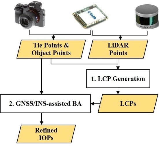
6. Methodology for IOP Refinement and Validation

This section starts with introducing the proposed IOP refinement strategy. The approach for evaluating the accuracy of the refined IOPs is then presented. Finally, a strategy for evaluating the similarity between two sets of camera IOPs is introduced to compare the refined IOPs from different initial values.

6.1. IOP Refinement

Instead of using GCPs for refining camera IOPs, the proposed strategy relies on control information extracted from LiDAR data that are acquired in the same mission. In the first step, the GNSS/INS-assisted SfM is adopted to generate a sparse point cloud and corresponding SIFT tie points using the original camera IOPs. As mentioned in Section 4, rather than the default DoG threshold in the SIFT detector (i.e., 0.007), a smaller threshold (0.003) is used in this study to extract more features and consequently generate more object points. Figure 10a,b shows the generated sparse point clouds using the two DoG thresholds, where using a smaller DoG threshold results in a significant improvement of the reconstruction results in terms of the distribution and number of object points. One should note that despite using a small DoG threshold in the SfM process, the distribution of object points is not ideal as a majority of the reconstructed object points still belong to the grassy area due to the existence of more distinctive features. It is worth noting that an uneven distribution of the control points would cause overweighting that could negatively impact the IOP refinement process [42]. To ensure a balanced and uniform distribution of the object points, in the next step, a distance-based down-sampling is performed on the generated sparse point cloud. In the down-sampling procedure, SIFT tie points corresponding to the eliminated object points are removed as well. A sample of down-sampled object points is shown in Figure 10c for the A-1 dataset.
Following the object/image points down-sampling, LCPs are generated by identifying the corresponding LiDAR point for each image-based point. The conceptual basis of the proposed strategy is identifying the projections of image-based points onto neighboring LiDAR surfaces that define planar regions, as illustrated in Figure 11. For a given point in an image-based point cloud (denoted by the blue point in Figure 11a), its closest LiDAR point is identified as a candidate corresponding point, as shown by the green point in Figure 11b. To ensure reliable correspondences, the distance between these two points must be smaller than a pre-defined value. Next, a spherical region with a pre-defined radius centered at the candidate corresponding point is created, as shown in Figure 11b. In this study, 1 and 0.5 m thresholds are used as the maximum distance and search radius, respectively. Then, an iterative plane fitting is conducted using all the LiDAR points within the spherical region, as shown in Figure 11c. Here, the term “iterative” refers to the removal of outliers based on the best-fitting plane from each iteration. In other words, the plane derived in a given iteration is used to identify and remove outlier points followed by a subsequent plane fitting conducted on the remaining points. A point is regarded as an outlier if its normal distance is more than a user-defined factor—2.5 in this implementation—multiplied by the RMSE of the normal distances of all the points. The remaining inlier points from each iteration are assigned weights that are inversely proportional to their corresponding normal distance from the best-fitting plane. This process is iterated till there are no more outliers and the finally obtained plane is designated as the best-fitting plane for the neighborhood. The plane is considered valid if the RMSE of the normal distances of the points from the best-fitting plane is smaller than a pre-defined threshold (0.3 m in this study), and the ratio of LiDAR points retained through the iterative plane fitting is more than 50%. Figure 11d shows the points retained through the iterative plane fitting. Finally, the projection of the image point onto the derived best-fitting plane is regarded as the final LiDAR point corresponding to the image point, as shown by the green point in Figure 11d.
The derived LiDAR points will be used as GCPs in the following BA. One should note that the resultant LCPs will be most reliable in the direction normal to the best-fitting plane, while less reliable in the two directions along the plane, which in turn, warrants the need to associate a weight matrix to each LCP in the BA step relaying the information about its reliability. To compute the weight matrix, let the local coordinate frame for the best-fitting plane be denoted by u v w , where the u , v -axes are along the plane and the w -axis is along the normal to the plane, as shown in Figure 11d. So, the weight matrix in the u v w -frame, denoted by P u v w , is formed by assigning a standard deviation to each of the u , v , w -directions, denoted by σ u ,   σ v ,   σ w , respectively. The standard deviations for the u and v directions are set to 1 m, while that for the w direction (normal to the plane) is considered as 5 cm. Consequently, the weight in the u v w -frame can be given by Equation (3a), which is then transformed to derive the corresponding weight matrix in the mapping frame ( P x y z ) using the rotation matrix, R x y z u v w , relating the u v w and the x y z frames (illustrated in Figure 11d), as given in Equation (3b). As a result, for each LCP, its weight matrix is derived based on the orientation of the corresponding best-fitting plane.
P u v w = [ 1 / σ u 2 0 0 0 1 / σ v 2 0 0 0 1 / σ w 2 ]
P x y z = R u v w x y z   P u v w   R x y z u v w
Now that the LiDAR-based GCPs are identified, the GNSS/INS-assisted bundle adjustment, which was introduced in Section 4, is carried out to refine the camera IOPs, namely principal distance ( c ) and distortion parameters ( K 1 , K 2 , P 1 , P 2 ) . The LCPs along with their weights serve as well-distributed control points, which can be helpful for refining system calibration parameters. According to the fact that in the implemented SfM strategy, the utilized camera IOPs are only used to restrict the search space for finding conjugate features, one can argue that the SIFT-based conjugate points are not significantly affected by those IOPs. As a result, these tie points can be used as observations in the bundle adjustment procedure for camera IOP refinement. In addition, as discussed in the bias impact analysis (Section 5), a variation in the principal distance would result in a constant shift in the vertical direction, which is identical to the impact of the Z component of the GNSS/INS trajectory, denoted as Z 0 . Therefore, in order to decouple the correlation between the camera principal distance and Z 0 of the GNSS/INS trajectory, the latter is treated as a constant value in the bundle adjustment procedure, i.e., very small variance is assigned to the corresponding prior information. Fixing Z 0 will not affect the accuracy of the estimated principal distance due to the fact that Z 0 is not contaminated by systematic errors. In other words, there is no systematic bias that will be absorbed by the principal distance. Through the GNSS/INS-assisted BA using LCPs, refined IOPs are estimated and their accuracy needs to be verified. The approaches for accuracy evaluation will be the focus of the forthcoming section.

6.2. Camera IOP Accuracy Evaluation

In order to evaluate the accuracy of the refined IOPs in the previous step, the LiDAR point cloud and RTK-GNSS measurements of the checkerboard targets are used as reference. Considering that the deployed targets do not cover the entire area, a well-distributed dense point cloud is also generated and then compared to the LiDAR data. This comparison can provide a more comprehensive evaluation of the refined IOPs. The approach used in this study for such evaluation is illustrated in Figure 12. In this approach, an image-based dense point cloud is first generated using the refined IOPs for a comparison with LiDAR data. As previously mentioned, the image-based dense point cloud outperforms its sparse counterpart in terms of the number of points as well as point distribution, thus resulting in a more reliable comparison with the LiDAR point cloud. To generate the image-based dense point cloud, a bundle adjustment procedure is first conducted using the SIFT-based tie points and refined IOPs from the previous step, and then camera EOPs are derived. One should note that, although camera EOPs are not a direct product of the BA process, they can be indirectly derived from the refined GNSS/INS trajectory and mounting parameters. Next, a dense point cloud is generated using the refined camera EOPs and IOPs. Once the dense point cloud for a given dataset is generated, a point-to-point correpondence is established between the LiDAR and image-based point clouds using the same strategy introduced in Section 6.1.
The image-based dense point cloud and their corresponding LiDAR points are used to derive the discrepancy between the two point clouds. The 3D discrepancies between point pairs are incorporated into an LSA model to quantify the net discrepancy [ d x   d y   d z ] T between the two point clouds. More specifically, the resultant 3D discrepancy between the coordinates of the image-based 3D point and its corresponding LiDAR point (derived using the approach described in Section 6.1) would be the normal distance ( n d ) of the former from the best-fitting plane through the latter. The discrepancy is oriented along the normal vector to the plane, thus mandating the incorporation of a modified weight matrix into the LSA model, which serves to nullify the components of the discrepancy in the directions along the best-fitting plane. The modified weight matrix for each point pair is derived based on the orientation of the corresponding best-fitting plane. Let the local coordinate system of the best-fitting plane be denoted as the u v w -frame, where w = [ w x   w y   w z ] T denotes the unit normal vector of the plane. The strategy proposed by Renaudin et al. [43] is used to derive the modified weight matrix, wherein the components of the discrepancy in the two directions ( u ,   v ) along the plane are nullified while retaining the component normal to the plane. As proposed by Renaudin et al. [43], the weight matrix in the local coordinate system for the point along the best-fitting plane can be modified in order to nullify components along the plane by replacing the elements corresponding to the u and v axes by zeros, henceforth denoted as the modified weight matrix, P u v w , as given by Equation (4). The modified weight matrix in the mapping frame, P x y z , can be derived by Equation (5).
P u v w = [ 0 0 0 0 0 0 0 0 P w ]
P x y z = R u v w x y z   P u v w   R x y z u v w
The difference in coordinates between an image-based 3D point and its corresponding point in the LiDAR data is denoted by [ d x ( obs )   d y ( obs )   d z ( obs ) ] T . In the LSA model, the differences between point coordinates from the image-based and LiDAR-based point clouds are treated as direct observations of the unknown net discrepancy [ d x   d y   d z ] T . The LSA model with a modified weight matrix is given by Equation (6), where the error in the observations, [ e d x ( obs )   e d y ( obs )   e d z ( obs ) ] T , is assumed to have a stochastic distribution with a mean of 0 and variance of σ 0 2 P + . Here, σ 0 denotes an a priori variance factor of the observed discrepancies and P + denotes the Moore–Penrose pseudo-inverse of the rank deficient modified weight matrix derived for each point pair depending on the orientation of the corresponding best-fitting plane in the LiDAR point cloud.
The LSA model is then solved to derive the estimates of the net discrepancy between the two point clouds, as given by Equation (7), where i denotes the point pair index. The dispersion matrix of the derived discrepancy estimates is given by Equation (8), where σ ^ 0 2 denotes an a posteriori variance factor of the LSA. The dispersion matrix serves as an indicator of the accuracy of the derived net discrepancy values, where a high variance would indicate low accuracy and vice versa. The accuracy of net discrepancy estimates would depend on the distribution of the orientation of the best-fitting planes corresponding to each image-to-LiDAR point pair.
[ d x ( obs ) d y ( obs ) d z ( obs ) ] = [ d x d y d z ] + [ e d x ( obs ) e d y ( obs ) e d z ( obs ) ] ;   [ e d x ( obs ) e d y ( obs ) e d z ( obs ) ] ( 0 ,   σ 0 2 P + )
[ d X ^ d y ^ d z ^ ] = ( A T P A ) 1 ( A T P y ) = ( P i ) 1 ( P i [ d x i ( obs ) d y i ( obs ) d z i ( obs ) ] )
D ^ { [ d x ^ d y ^ d z ^ ] } = σ ^ 0 2 ( P i ) 1
In addition to evaluating the accuracy of refined IOPs through comparison with LiDAR data, the accuracy of the image-based reconstruction is also assessed against the RTK-GNSS measurements of the twelve checkerboard targets that were set up in the field. To do so, the center points of the checkerboard targets are manually identified in the visible images. The object coordinates of the targets are then estimated through a multi-light ray intersection, using refined IOPs and EOPs from the BA procedure. Once the coordinates of targets are estimated, these coordinates are compared with the RTK-GNSS measurements, and the mean and STD of the coordinate differences are reported.

6.3. Camera IOP Consistency Analysis

In order to evaluate the robustness of the proposed strategy, the impact of the initial camera parameters on refined IOPs will be investigated. Therefore, consistency analysis approaches need to be established for comparing the refined IOPs from different initial values. This comparison is conducted by separately evaluating the similarity between two IOP sets in terms of principal distance and distortion parameters. To evaluate the impact of different principal distances, their difference is first calculated and then the impact of such difference on the Z coordinates of the object points is derived using Equation (2). The comparison between camera distortion parameters coming from two IOP sets starts with defining a virtual regular grid (the grid size is 90×90 pixels in this study) on the image plane. Then, using each set of distortion parameters, distortion-free coordinates of the grid vertices are calculated. Next, RMSE and maximum differences between the two distortion-free grid vertices are reported as a measure of the similarity of the two IOP sets.

7. Experimental Results and Discussion

In this section, the absolute accuracy of the LiDAR- and image-based point clouds generated using original system calibration parameters are first reported to verify the following hypotheses: (i) LiDAR system calibration is stable and derived data are accurate enough to be used as a source of control for in situ IOP refinement, and (ii) the accuracy of the image-based point cloud is negatively affected by inaccurate system calibration parameters due to the instability of the camera IOPs. The feasibility of the IOP refinement strategy is then evaluated for the seven datasets over two sites. In addition, to evaluate the robustness of the proposed strategy, this study investigates the sensitivity of the IOP refinement strategy to the initial estimates of camera IOPs.

7.1. Accuracy of LiDAR and Image-based Point Cloud

In this subsection, the accuracy of the image- and LiDAR-based point clouds derived using the original system calibration parameters is assessed through a comparison with RTK-GNSS measurements of the target centers for the seven datasets. The comparison is conducted as follows:
  • Image-based point cloud: Similar to the strategy introduced in Section 6.2, the center points of the twelve checkerboard targets are manually identified in the visible images. Then, using the original camera IOPs as well as refined EOPs derived from the GNSS/INS-assisted SfM procedure, 3D coordinates of the target centers are estimated through a multi-light ray intersection. Finally, the differences between the estimated and RTK-GNSS coordinates of the targets are calculated, and the statistics including the mean and STD are reported.
  • LiDAR-based point cloud: In order to evaluate the absolute accuracy of the LiDAR point cloud, centers of the highly reflective checkerboard targets are first manually identified from the LiDAR point cloud based on the intensity information, and denoted as initial points. The initial points are expected to have an accuracy of ±3 to ±5 cm due to the noise level of the LiDAR data caused by (i) the GNSS/INS trajectory errors, (ii) laser range/orientation measurements errors, and (iii) the nature of LiDAR pulse returns from highly reflective surfaces. Then, the strategy proposed in Section 6.1 is used to derive the best-fitting plane in the neighborhood of the initial points, and reliable Z coordinates are derived by projecting the initial points onto the defined planes. Afterwards, the accuracy of the LiDAR point clouds is assessed by evaluating the differences between the LiDAR-based and corresponding RTK-GNSS coordinates for the twelve target centers.
Table 4 reports the mean and STD of the differences between the image-based/LiDAR-based and RTK-GNSS coordinates of the twelve target centers for the seven datasets. According to the statistics reported in Table 4, there is a misalignment between the image-based point clouds and RTK-GNSS measurements of the targets in the X, Y, and Z directions. By comparing datasets collected with the same camera settings on different dates, i.e., A-1/A-2, B-1/B-2, and C-1/C-2, one can observe that the accuracy of the reconstructed point clouds is getting worse over time. Among all these settings, IOPs under auto focus mode are found to be most unstable. Overall, the misalignments between the image-based and RTK-GNSS coordinates prove that the original set of camera IOPs coming from the in situ self-calibration procedure lead to an inaccurate object space for all seven datasets due to the instability of IOPs.
As for the accuracy assessment results of the LiDAR point clouds for the seven datasets listed in Table 4, the differences in the X and Y directions for all datasets are within 5 cm. One should note that these planimetric differences arise from the difficulty in identifying the actual center of targets in the LiDAR data. Further, according to the Z differences presented in Table 4, mean and STD values in the vertical direction are in the range of 1–3 cm. These values are within the expected LiDAR accuracy (around 3–5 cm). Overall, the small mean and STD values reported in Table 4 verify the accuracy of the LiDAR data over different dates (i.e., the LiDAR unit maintains the stability of its system calibration parameters over time). Furthermore, the agreement between LiDAR and RTK-GNSS coordinates shows that LiDAR data can be used as a reference surface for IOP refinement.

7.2. IOP Refinement Results

The original camera IOPs estimated from the in situ self-calibration procedure as well as the refined IOPs estimated from the proposed strategy using the original set of IOPs as initial values for the seven datasets are presented in Table 5. In this table, the standard deviation of each estimated parameter and the derived square root of the a posteriori variance factor ( σ ^ 0 ) from the BA procedure are also reported. In the BA procedure, the weight matrix for the LSA model is derived by inverting the variance–covariance matrix for the SIFT-based image coordinate measurements and the GNSS/INS trajectory information. The a priori variances for the image coordinate measurements are set to (7 pixels)2. In terms of the GNSS/INS information, the a priori variances for the position, roll/pitch angles, and heading angle are set to be (3 cm) 2, (0.025°)2, and (0.08°)2, respectively. In this case, the value of σ ^ 0 is ideally expected to be close to 1. As presented in Table 5, σ ^ 0 values for all the datasets turn out to be significantly less than 1, which indicates that the assigned a priori variances for the image coordinate observations (which constitute a vast majority of the observations) are too conservative. For instance, σ ^ 0 of 0.4 reveals that the image coordinate accuracy is roughly 2.8 pixels instead of 7 pixels. The estimated parameters are not highly correlated except for the radial distortion coefficients K 1 and K 2 , which is expected due to their similar impact. Based on the low correlation as well as small STDs of the estimated IOPs in Table 5, one can conclude that the camera IOPs can be estimated accurately using the LiDAR data as a reference.

7.3. Accuracy Analysis of Refined IOPs

In this section, refined IOPs are first evaluated through a comparison between LiDAR and image-based dense point clouds. To do so, as mentioned in Section 6.2, correspondences between the two point clouds are first established, then the modified weight matrix-based LSA is used to estimate the net X, Y, and Z discrepancies ( d x , d y , d z ). The estimated discrepancies and corresponding σ ^ 0 for the seven datasets are presented in Table 6. The derived σ ^ 0 in the LSA procedures represents the average distance between the image–LiDAR point pairs, which is around 5 cm for all datasets. The estimated X and Y discrepancies for the seven datasets are in the range of -2 to -4 cm and -3 to 6 cm, respectively, while the Z discrepancy ranges from -2 to 2 cm. A principal component analysis (PCA)-based dimensionality analysis is carried out on the dispersion matrix of the estimated net discrepancy vector. The principal components (eigenvectors) represent the directions of the discrepancies that exhibit a maximum amount of variance in the mapping frame, while the corresponding eigenvalues denote the variances along these directions. The analysis results for four sample datasets are listed in Table 7, where the derived principal components along with the corresponding percentage of total variance are presented. It is worth mentioning that similar results are observed for all datasets and therefore, only the results for the A-1, B-2, C-2, and D datasets are presented. It can be observed from the table that the third principal component for each dispersion matrix (highlighted in red) is almost parallel to the Z direction, and the corresponding variance only accounts for less than 1% of the total variance. The other two principal components with high variance percentages are aligned along the planimetric directions. Such an observation reveals that the Z discrepancy estimate is the most reliable component. One should note that the orientation distribution of the planes used for evaluating the discrepancy contributes to the accuracy of the discrepancy estimates. In this study, the captured aerial images mainly lead to the reconstruction of points along surfaces that are mostly horizontal (e.g., grassy area, pavement, or building roofs). While all such object points contribute to the estimation of the Z discrepancy between point clouds, current estimates of horizontal discrepancy are derived using points belonging to very few surfaces that exhibit mild slopes, such as gable roofs for the datasets over Site I. It is worth mentioning that the noise level in the building roof area of the generated image-based dense point cloud is higher than other parts of the point cloud due to the homogeneous texture of the gable roof. As a result, the horizontal discrepancy derived in the LSA procedure cannot reflect the actual X and Y accuracy of the generated image-based point cloud. In conclusion, the comparison against LiDAR data verifies the vertical accuracy and horizontal accuracy—to a lesser degree—of the image-based point cloud derived using the refined IOPs.
In addition to comparing the derived image-based point cloud with LiDAR data, the accuracy of the refined IOPs is evaluated through a comparison between the image-based and RTK-GNSS coordinates of the twelve checkerboard targets. Table 8 reports the differences between the two sets of target coordinates. Comparing Table 8 with Table 4, one can note that the accuracy of the image-based point cloud is significantly improved after the IOP refinement in all the X, Y, and Z directions for the seven datasets. It is also clear from Table 8 that using the refined IOPs, a horizontal accuracy of 1–2 cm can be achieved for all datasets. However, the differences in the Z direction range from 2 to 5 cm, which is an indication of a worse Z accuracy of the point cloud when compared with the planimetric accuracy. The larger differences in the Z direction are mainly due to the fact that the LiDAR point cloud which was used as a reference surface for the IOP refinement and RTK-GNSS measurements is not perfectly aligned in the Z direction, where a 2 to 3 cm shift was found in the comparison between the LiDAR data and RTK-GNSS measurements, as shown in Table 4. Moreover, it can be seen from Table 6 and Table 8 that the accuracy of the reconstructed point clouds using refined IOPs for the datasets with auto focus mode (A and D datasets) is at the same level as the datasets with manual focus mode (B and C datasets). This verifies the hypothesis that the IOPs remain the same during data acquisition under auto focus mode. According to the results reported above, one can observe that by using the refined IOPs, accurate image-based 3D point clouds can be generated for all datasets over the two study sites.

7.4. Impact of the Initial Camera Parameters on Refined IOPs

As mentioned earlier, the proposed IOP refinement strategy is based on the hypothesis that the SIFT-based tie points are not significantly affected by the camera IOPs. Consequently, it is expected that if different sets of initial camera IOPs are used for conducting the refinement procedure, similar camera parameters will be achieved through the refinement strategy. Besides the IOPs from the in situ self-calibration, another set of IOPs estimated from the indoor calibration procedure is used for the IOP refinement strategy. These two sets of camera IOPs, denoted as IOP-1 and IOP-2, are listed in Table 9, and the refined IOPs estimated starting with these initial sets for the seven datasets are presented in Table 10.
To check the equivalency between the two sets of refined IOPs derived from different initial IOP sets, the consistency analysis introduced in Section 6.3 is performed to evaluate the similarity in terms of principal distance and distortion parameters. The results of this IOP equivalency analysis for the seven datasets are presented in Table 11, where the absolute differences in principal distance are within 6 pixels, leading to 3 cm variation in the Z coordinate of the object points at a 41 m flying height. In terms of the distortion parameters comparison, the RMSE values of the differences between the two sets of distortion-free grid vertices are not significant, i.e., smaller than 0.2 pixels for both x and y coordinates for all datasets, with a maximum difference less than 1 pixel. Based on the conducted camera IOP consistency analysis, the refined IOPs derived from the different initial estimates are equivalent. Thus, we confirmed the hypothesis that the established SIFT-based points through the GNSS/INS-assisted SfM do not depend on the initial IOPs.

8. Conclusions and Recommendations for Future Work

In this paper, a new strategy has been proposed for in situ IOP refinement. The key motivation for such development is eliminating the need for control targets, which are subject to the following drawbacks: (i) deploying these targets in the test field is an expensive, time-consuming, and labor-intensive process, and (ii) the spatial coverage and distribution of targets would be sub-optimal for IOP refinement due to the limited number of manually deployed targets. Instead of using GCPs, the proposed strategy exploited the available, highly accurate LiDAR data—collected simultaneously with imagery—to derive adequate and well-distributed control points for refining camera IOPs. Seven datasets over two study sites with different geomorphic features were used to evaluate the performance of the developed strategy. Below are the findings of the presented study:
  • LiDAR data are verified to be a reliable source of control for IOP refinement due to two reasons: (i) LiDAR system calibration parameters were shown to be stable over time and the derived point clouds were accurate based on a comparison with the RTK-GNSS measurements of the checkerboard targets, and (ii) LiDAR data over any type of terrain cover were proven to be sufficient for IOP refinement based on the presented bias impact analysis.
  • The proposed strategy eliminates the need for any targets or specific flight configuration as long as sufficient overlap and side-lap are ensured among the images. The IOP refinement process can be conducted more frequently and even for each individual data collection mission to ensure a good accuracy of the photogrammetric products when using off-the-shelf digital cameras.
  • The IOP refinement results from the seven datasets over the two study sites showed small standard deviation values for the estimated camera parameters as well as low correlation among those parameters (except for K 1 / K 2 ). This indicates that the refined IOPs are estimated accurately. Further, image-based point clouds while using the refined IOPs showed a good agreement with both the LiDAR point cloud and RTK-GNSS measurements of the checkerboard targets, with an accuracy in the range of 3–5 cm at a 41 m flying height. This accuracy was within the expected accuracy considering the errors from the direct georeferencing as well as LiDAR data. In addition, to validate the robustness of the proposed strategy, its sensitivity to the initial camera IOPs was investigated. The results revealed that by using different sets of initial camera parameters, similar refined IOPs are derived.
The limitation of the proposed strategy is that the IOP refinement is conducted in a two-step procedure—(i) the LiDAR point cloud is first processed to generate the control surface, which is later used for the identification of LCPs, and (ii) GNSS/INS-assisted BA is conducted using the derived LCPs to refine camera IOPs—which is computationally expensive. To overcome this limitation, future work will focus on investigating a single-step integration of LiDAR data in the GNSS/INS-assisted SfM and self-calibration strategy. Another focus in the future would be to adapt the proposed IOP refinement strategy to other MMS units equipped with different types of camera and LiDAR sensors.

Author Contributions

Conceptualization, T.Z. and A.H.; methodology, T.Z., S.M.H., R.R. and A.H.; formal analysis, T.Z. and S.M.H.; data curation, T.Z. and S.M.H.; writing—original draft preparation, T.Z., S.M.H. and R.R.; writing—review and editing, A.H., T.Z., S.M.H. and R.R.; supervision, A.H. All authors have read and agreed to the published version of the manuscript.

Funding

The information, data, or work presented herein was funded in part by the Civil Engineering Center for Applications of UAS for a Sustainable Environment (CE CAUSE) and the Advanced Research Projects Agency Energy (ARPA E), U.S. Department of Energy, under Award Number DE AR0001135. The views and opinions of authors expressed herein do not necessarily state or reflect those of the United States Government or any agency thereof.

Acknowledgments

Special acknowledgment is given to the Purdue TERRA team and the members of the Digital Photogrammetry Research Group (DPRG) for their work on system integration and data collections.

Conflicts of Interest

The authors declare no conflict of interest.

References

  1. Habib, A.; Zhou, T.; Masjedi, A.; Zhang, Z.; Flatt, J.E.; Crawford, M. Boresight calibration of GNSS/INS-assisted push-broom hyperspectral scanners on UAV platforms. IEEE J. Sel. Top. Appl. Earth Obs. Remote Sens. 2018, 11, 1734–1749. [Google Scholar] [CrossRef]
  2. Moghimi, A.; Yang, C.; Anderson, J.A. Aerial hyperspectral imagery and deep neural networks for high-throughput yield phenotyping in wheat. Comput. Electron. Agric. 2020, 172, 105299. [Google Scholar] [CrossRef] [Green Version]
  3. Ravi, R.; Hasheminasab, S.M.; Zhou, T.; Masjedi, A.; Quijano, K.; Flatt, J.E.; Crawford, M.; Habib, A. UAV-based multi-sensor multi-platform integration for high throughput phenotyping. In Autonomous Air and Ground Sensing Systems for Agricultural Optimization and Phenotyping IV; SPIE: Baltimore, MD, USA, 2019; p. 110080E. [Google Scholar]
  4. Masjedi, A.; Zhao, J.; Thompson, A.M.; Yang, K.-W.; Flatt, J.E.; Crawford, M.M.; Ebert, D.S.; Tuinstra, M.R.; Hammer, G.; Chapman, S. Sorghum biomass prediction using UAV-based remote sensing data and crop model simulation. In Proceedings of the IGARSS 2018-2018 IEEE International Geoscience and Remote Sensing Symposium, Valencia, Spain, 22–27 July 2018; pp. 7719–7722. [Google Scholar]
  5. Habib, A.; Xiong, W.; He, F.; Yang, H.L.; Crawford, M. Improving orthorectification of UAV-based push-broom scanner imagery using derived orthophotos from frame cameras. IEEE J. Sel. Top. Appl. Earth Obs. Remote Sens. 2016, 10, 262–276. [Google Scholar] [CrossRef]
  6. Shakhatreh, H.; Sawalmeh, A.H.; Al-Fuqaha, A.; Dou, Z.; Almaita, E.; Khalil, I.; Othman, N.S.; Khreishah, A.; Guizani, M. Unmanned aerial vehicles (UAVs): A survey on civil applications and key research challenges. IEEE Access 2019, 7, 48572–48634. [Google Scholar] [CrossRef]
  7. Ham, Y.; Han, K.K.; Lin, J.J.; Golparvar-Fard, M. Visual monitoring of civil infrastructure systems via camera-equipped Unmanned Aerial Vehicles (UAVs): A review of related works. Vis. Eng. 2016, 4, 1. [Google Scholar] [CrossRef] [Green Version]
  8. Greenwood, W.W.; Lynch, J.P.; Zekkos, D. Applications of UAVs in civil infrastructure. J. Infrastruct. Syst. 2019, 25, 04019002. [Google Scholar] [CrossRef]
  9. Lin, Y.-C.; Cheng, Y.-T.; Zhou, T.; Ravi, R.; Hasheminasab, S.M.; Flatt, J.E.; Troy, C.; Habib, A. Evaluation of UAV LiDAR for Mapping Coastal Environments. Remote Sens. 2019, 11, 2893. [Google Scholar] [CrossRef] [Green Version]
  10. Hamilton, S.; Stephenson, J. Testing UAV (drone) aerial photography and photogrammetry for archeology. Lakehead Univ. Tech. Rep. 2016, 1, 1–43. [Google Scholar]
  11. Nex, F.; Remondino, F. UAV for 3D mapping applications: A review. Appl. Geomat. 2014, 6, 1–15. [Google Scholar] [CrossRef]
  12. Habib, A.; Pullivelli, A.; Mitishita, E.; Ghanma, M.; Kim, E.M. Stability analysis of low-cost digital cameras for aerial mapping using different georeferencing techniques. Photogramm. Rec. 2006, 21, 29–43. [Google Scholar] [CrossRef]
  13. Habib, A.; Schenk, T. Accuracy analysis of reconstructed points in object space from direct and indirect exterior orientation methods. In OEEPE Workshop on Integrated Sensor Orientation; Federal Agency for Cartography and Geodesy BKG: Frankfurt, Germany, 2001; pp. 17–18. [Google Scholar]
  14. Hastedt, H.; Luhmann, T. Investigations on the quality of the interior orientation and its impact in object space for UAV photogrammetry. Int. Arch. Photogramm. Remote Sens. Spat. Inf. Sci. 2015, 40, 321–348. [Google Scholar] [CrossRef] [Green Version]
  15. Zhang, Z. Camera calibration with one-dimensional objects. IEEE Trans. Pattern Anal. Mach. Intell. 2004, 26, 892–899. [Google Scholar] [CrossRef] [PubMed]
  16. Zhang, Z. A flexible new technique for camera calibration. IEEE Trans. Pattern Anal. Mach. Intell. 2000, 22, 1330–1334. [Google Scholar] [CrossRef] [Green Version]
  17. He, F.; Habib, A. Target-based and Feature-based Calibration of Low-cost Digital Cameras with Large Field-of-view. In Proceedings of the ASPRS 2015 Annual Conference, Tampa, FL, USA, 4–8 May 2015. [Google Scholar]
  18. Habib, A.; Lari, Z.; Kwak, E.; Al-Durgham, K. Automated detection, localization, and identification of signalized targets and their impact on digital camera calibration. Rev. Bras. Cartogr. 2013, 65, 4. [Google Scholar]
  19. Remondino, F.; Fraser, C. Digital camera calibration methods: Considerations and comparisons. Int. Arch. Photogramm. Remote Sens. 2006, 36, 266–272. [Google Scholar]
  20. Duane, C.B. Close-range camera calibration. Photogramm. Eng. 1971, 37, 855–866. [Google Scholar]
  21. Habib, A.; Morgan, M. Stability analysis and geometric calibration of off-the-shelf digital cameras. Photogramm. Eng. Remote Sens. 2005, 71, 733–741. [Google Scholar] [CrossRef] [Green Version]
  22. Mitishita, E.; Côrtes, J.; Centeno, J.; Machado, A.M.L.; Martins, M. Study of stability analysis of the interior orientation parameters from the small-format digital camera using on-the-job calibration. In Proceedings of the Canadian Geomatics Conference, Calgary, AB, Canada, 15–18 June 2010. [Google Scholar]
  23. Honkavaara, E.; Ahokas, E.; Hyyppä, J.; Jaakkola, J.; Kaartinen, H.; Kuittinen, R.; Markelin, L.; Nurminen, K. Geometric test field calibration of digital photogrammetric sensors. ISPRS J. Photogramm. Remote Sens. 2006, 60, 387–399. [Google Scholar] [CrossRef]
  24. Jacobsen, K. Geometry of digital frame cameras. In Proceedings of the ASPRS Annual Conference, Tampa, FL, USA, 7–11 May 2007. [Google Scholar]
  25. Cramer, M.; Przybilla, H.J.; Zurhorst, A. UAV cameras: Overview and geometric calibration benchmark. Int. Arch. Photogramm. Remote Sens. Spat. Inf. Sci. 2017, 42, 85. [Google Scholar] [CrossRef] [Green Version]
  26. Gneeniss, A.S.; Mills, J.P.; Miller, P.E. In-flight photogrammetric camera calibration and validation via complementary lidar. ISPRS J. Photogramm. Remote Sens. 2015, 100, 3–13. [Google Scholar] [CrossRef] [Green Version]
  27. Costa, F.A.L.; Mitishita, E.A.; Centeno, J.A.S. A study of integration of LIDAR and photogrammetric data sets by indirect georeferencing and in situ camera calibration. Int. J. Image Data Fusion 2017, 8, 94–111. [Google Scholar] [CrossRef]
  28. Applanix. Apx-15 UAV Datasheet. Available online: https://www.applanix.com/downloads/products/specs/APX15_UAV.pdf (accessed on 8 June 2020).
  29. Sony. α7R III Full Specifications and Features. Available online: https://www.sony.com/electronics/interchangeable-lens-cameras/ilce-7m3-body-kit/specifications (accessed on 8 June 2020).
  30. Elbahnasawy, M. GNSS/INS-Assisted Multi-Camera Mobile Mapping: System Architecture, Modeling, Calibration, and Enhanced Navigation. Ph.D. Dissertation, Purdue University, West Lafayette, IN, USA, 2018. [Google Scholar]
  31. Velodyne. Puck LITE Data Sheet. Available online: http://www.mapix.com/wp-content/uploads/2018/07/63-9286_Rev-H_Puck-LITE_Datasheet_Web.pdf (accessed on 8 June 2020).
  32. Light, D.L. The new camera calibration system at the US Geological Survey. Photogramm. Eng. Remote Sens. 1992, 58, 185–188. [Google Scholar]
  33. Ravi, R.; Lin, Y.-J.; Elbahnasawy, M.; Shamseldin, T.; Habib, A. Simultaneous system calibration of a multi-lidar multicamera mobile mapping platform. IEEE J. Sel. Top. Appl. Earth Obs. Remote Sens. 2018, 11, 1694–1714. [Google Scholar] [CrossRef]
  34. Luhmann, T.; Fraser, C.; Maas, H.G. Sensor modelling and camera calibration for close-range photogrammetry. ISPRS J. Photogramm. Remote Sens. 2016, 115, 37–46. [Google Scholar] [CrossRef]
  35. Trimble. Trimble R10 Model 2 GNSS System. Available online: https://geospatial.trimble.com/sites/geospatial.trimble.com/files/2019-04/022516-332A_TrimbleR10-2_DS_USL_0419_LR.pdf (accessed on 8 June 2020).
  36. Hasheminasab, S.M.; Zhou, T.; Habib, A. GNSS/INS-Assisted Structure from Motion Strategies for UAV-Based Imagery over Mechanized Agricultural Fields. Remote Sens. 2020, 12, 351. [Google Scholar] [CrossRef] [Green Version]
  37. Lowe, D.G. Distinctive image features from scale-invariant keypoints. Int. J. Comput. Vis. 2004, 60, 91–110. [Google Scholar] [CrossRef]
  38. He, F.; Zhou, T.; Xiong, W.; Hasheminnasab, S.M.; Habib, A. Automated aerial triangulation for UAV-based mapping. Remote Sens. 2018, 10, 1952. [Google Scholar] [CrossRef] [Green Version]
  39. Furukawa, Y.; Ponce, J. Accurate, dense, and robust multiview stereopsis. IEEE Trans. Pattern Anal. Mach. Intell. 2009, 32, 1362–1376. [Google Scholar] [CrossRef]
  40. El-Sheimy, N.; Valeo, C.; Habib, A. Digital Terrain Modeling: Acquisition, Manipulation, and Applications; Artech House Inc.: Norwood, MA, USA, 2005. [Google Scholar]
  41. Zhou, Y.; Rupnik, E.; Meynard, C.; Thom, C.; Pierrot-Deseilligny, M. Simulation and Analysis of Photogrammetric UAV Image Blocks—Influence of Camera Calibration Error. Remote Sens. 2020, 12, 22. [Google Scholar] [CrossRef] [Green Version]
  42. Rangel, J.M.G.; Gonçalves, G.R.; Pérez, J.A. The impact of number and spatial distribution of GCPs on the positional accuracy of geospatial products derived from low-cost UASs. Int. J. Remote Sens. 2018, 39, 7154–7171. [Google Scholar] [CrossRef]
  43. Renaudin, E.; Habib, A.; Kersting, A.P. Featured-Based Registration of Terrestrial Laser Scans with Minimum Overlap Using Photogrammetric Data. Etri J. 2011, 33, 517–527. [Google Scholar] [CrossRef]
Figure 1. Flowchart of the proposed interior orientation parameters (IOP) refinement strategy.
Remotesensing 12 02268 g001
Figure 2. The unmanned aerial vehicle (UAV)-based mobile mapping system and onboard sensors used in this study.
Remotesensing 12 02268 g002
Figure 3. Study sites (a) I and (b) II with red boxes highlighting the deployed checkboard targets (denoted as T1-T12), as well as (c) sample images of the targets.
Remotesensing 12 02268 g003
Figure 4. Top view of the flight trajectory (colored by time) superimposed on orthophotos of (a) Site I for the A-1 dataset and (b) Site II for the D dataset.
Remotesensing 12 02268 g004
Figure 5. Generated orthophoto and point clouds (colored by height) for the A-1 dataset: (a) orthophoto, (b) image-based sparse point cloud with 20,000 points, (c) image-based dense point cloud with 80,000 points, and (d) LiDAR point cloud with 31,000,000 points.
Remotesensing 12 02268 g005
Figure 6. Impact of a bias in the principal distance ( δ c ) on object point coordinates.
Remotesensing 12 02268 g006
Figure 7. Top view of the sparse point cloud colored by (a) X discrepancy, (b) Y discrepancy, and (c) Z discrepancy caused by a bias in the principal distance for the A-1 dataset.
Remotesensing 12 02268 g007
Figure 8. Top view of the sparse point cloud colored by (a) X discrepancy, (b) Y discrepancy, and (c) Z discrepancy caused by a bias in the radial distortion coefficient, K 1 , for the A-1 dataset.
Remotesensing 12 02268 g008
Figure 9. Top view of the sparse point cloud colored by (a) X discrepancy, (b) Y discrepancy, and (c) Z discrepancy caused by a bias in the decentering distortion coefficient, P 1 , for the A-1 dataset.
Remotesensing 12 02268 g009
Figure 10. Generated sparse point cloud (colored by height) using (a) the default difference of Gaussian (DoG) threshold of 0.007 with 25,000 points, (b) smaller DoG threshold of 0.003 with 40,000 points, as well as (c) down-sampled sparse point cloud with 3000 points for the A-1 dataset.
Remotesensing 12 02268 g010
Figure 11. Schematic illustration of deriving the corresponding point for an image-based 3D point from a LiDAR-based point cloud: (a) image-based 3D point (blue) and LiDAR points (red), (b) closest LiDAR point (green) and corresponding spherical region for extracting neighboring points, (c) retained neighboring points within spherical neighborhood and corresponding best-fitting plane, and (d) 3D points retained through iterative plane fitting and the projection of the image point (blue) on the best-fitting plane (green) to derive the corresponding LiDAR point.
Remotesensing 12 02268 g011
Figure 12. Flowchart of the proposed camera IOP accuracy validation strategy.
Remotesensing 12 02268 g012
Table 1. Flight configuration and camera settings of the flight missions captured for the experimental datasets.
Dataset NameDateStudy SiteCamera Focus SettingsFlying Height
(m)
Ground Speed
(m/s)
Lateral Distance 1
(m)
Overlap/
Side-Lap 2
(%)
Number of Images
A-120200304Site IAuto focus414.06.083/89209
A-220200501210
B-120200304Site IManual focus (32 m)414.06.083/89209
B-220200501210
C-120200317Site IManual focus (41 m)414.06.083/89211
C-220200501211
D20200221Site IIAuto focus414.09.578/77255
1 Lateral distance for east–west flights. 2 Imagery overlap and side-lap for east–west flights.
Table 2. Reference and biased IOPs used in the bias impact analysis (biased parameters are colored in red).
x p
(pixel)
y p
(pixel)
c
(pixel)
K 1
(10−10 pixel−2)
K 2
(10−17 pixel−4)
P 1
(10−7 pixel−1)
P 1
(10−8 pixel−1)
Reference IOPs27.55−8.708025.118.01−5.231.48−6.92
Biased IOPs ( c )8005.118.011.48
Biased IOPs ( K 1 )8025.117.011.48
Biased IOPs ( P 1 )8025.118.015.48
Table 3. Mean and standard deviation (STD) of the differences in object point coordinates caused by a bias introduced to the reference camera IOPs for the A-1 dataset.
Statistics Criteria X d i f (m) Y d i f (m) Z d i f (m)
Bias in c Mean−0.010.010.10
STD0.000.000.01
Bias in K 1 Mean0.000.00−0.03
STD0.050.050.03
Bias in P 1 Mean0.000.010.01
STD0.020.020.05
Table 4. Mean and STD of the differences between image-based/LiDAR-based and real-time kinematic-global navigation satellite systems (RTK-GNSS) coordinates of the twelve checkerboard targets for the seven datasets.
DatasetStatistics CriteriaImage-Based vs. RTK-GNSSLiDAR-Based vs. RTK-GNSS
X d i f (m) Y d i f (m) Z d i f (m) X d i f (m) Y d i f (m) Z d i f (m)
A-1Mean0.020.020.090.030.010.03
STD0.020.040.030.020.030.01
A-2Mean0.040.000.17−0.010.000.01
STD0.060.100.030.030.020.02
B-1Mean0.000.000.08−0.020.010.03
STD0.020.030.020.030.050.02
B-2Mean−0.010.000.10−0.010.010.01
STD0.030.030.020.030.030.02
C-1Mean0.000.010.06−0.01−0.020.03
STD0.040.040.020.040.030.02
C-2Mean−0.020.010.08−0.020.020.01
STD0.040.040.030.030.020.02
DMean0.01−0.020.07−0.020.01−0.02
STD0.040.050.020.030.040.02
Table 5. Original and refined IOPs from the proposed IOP refinement strategy for the seven datasets.
Dataset σ ^ 0 c
(pixel)
K 1
(10−10 pixel−2)
K 2
(10−17 pixel−4)
P 1
(10−7 pixel−1)
P 2
(10−8 pixel−1)
Original8025.118.01−5.231.48−6.92
A-10.388025.51 ± 0.698.33 ± 0.12−5.64 ± 0.051.15 ± 0.04−7.30 ± 0.43
A-20.348026.13 ± 0.577.76 ± 0.09−5.54 ± 0.041.10 ± 0.03−7.84 ± 0.31
B-10.258033.71 ± 0.448.53 ± 0.07−5.47 ± 0.031.21 ± 0.02−8.66 ± 0.27
B-20.248034.45 ± 0.398.33 ± 0.06−5.43 ± 0.031.14 ± 0.02−8.67 ± 0.21
C-10.288034.66 ± 0.388.58 ± 0.06−5.42 ± 0.031.06 ± 0.02−9.21 ± 0.23
C-20.238036.33 ± 0.378.46 ± 0.06−5.46 ± 0.031.14 ± 0.02−7.27 ± 0.20
D0.328030.31 ± 0.428.52 ± 0.08−5.72 ± 0.031.46 ± 0.02−8.32 ± 0.28
Table 6. Estimated X, Y, and Z discrepancies between the image-based dense point clouds generated using the refined IOPs and LiDAR point clouds for the seven datasets.
Dataset σ ^ 0
(m)
d x
(m)
d y
(m)
d z
(m)
A-10.05−0.030.050.00
A-20.05−0.020.010.00
B-10.05−0.040.050.00
B-20.05−0.020.030.00
C-10.04−0.030.040.02
C-20.05−0.020.02−0.01
D0.020.00−0.03−0.02
Table 7. Principal component analysis (PCA) of the dispersion matrix from least squares adjustment (LSA) when solving for the discrepancy between the image-based dense point cloud and LiDAR data for the A-1, B-2, C-2, and D datasets (third principal components indicating the direction of most reliable discrepancy estimates and corresponding variance percentages are colored in red).
DatasetPercentage of VariancePrincipal Components
A-154.4%(−0.199, 0.979, −0.034)
44.7%(−0.980, −0.200, 0.022)
0.9%(−0.029, 0.029, 0.999)
B-252.2%(−0.736, 0.675, −0.039)
47.0%(0.676, 0.736, −0.007)
0.8%(−0.025, 0.032, 0.999)
C-252.1%(−0.776, 0.630, −0.038)
47.1%(0.630, 0.776, −0.008)
0.8%(−0.025, 0.030, 0.999)
D58.4%(−0.664, 0.748, 0.010)
41.4%(0.748, 0.664, 0.006)
0.2%(0.002, 0.011, 0.999)
Table 8. Mean and STD of the differences between estimated coordinates using the refined IOPs and RTK-GNSS measurements of the twelve targets for the seven datasets.
DatasetStatistics Criteria X d i f (m) Y d i f (m) Z d i f (m)
A-1Mean0.010.010.04
STD0.010.020.03
A-2Mean−0.010.010.01
STD0.010.020.02
B-1Mean0.01−0.010.03
STD0.010.010.03
B-2Mean−0.010.000.02
STD0.010.020.02
C-1Mean0.000.010.04
STD0.010.010.02
C-2Mean0.000.010.01
STD0.020.020.03
DMean0.00−0.01−0.03
STD0.010.020.01
Table 9. Two sets of camera parameters for evaluating the impact of initial values on refined IOPs.
c
(pixel)
K 1
(10−10 pixel−2)
K 2
(10−17 pixel−4)
P 1
(10−7 pixel−1)
P 1
(10−8 pixel−1)
IOP-18025.118.01−5.231.48−6.92
IOP-28030.458.41−5.061.36−8.76
Table 10. Refined IOPs derived from IOP-1 and IOP-2 as initial values for the seven datasets.
DatasetInitial IOPs c
(pixel)
K 1
(10−10 pixel−2)
K 2
(10−17 pixel−4)
P 1
(10−7 pixel−1)
P 1
(10−8 pixel−1)
A-1IOP-18025.518.33−5.641.15−7.30
IOP-28027.228.39−5.641.13−6.39
A-2IOP-18026.137.76−5.541.10−7.84
IOP-28029.077.62−5.481.07−7.66
B-1IOP-18033.718.53−5.471.21−8.66
IOP-28037.528.51−5.431.24−8.36
B-2IOP-18034.458.33−5.431.14−8.67
IOP-28039.538.39−5.641.13−6.39
C-1IOP-18034.668.58−5.421.06−9.21
IOP-28038.378.53−5.391.02−8.98
C-2IOP-18036.338.46−5.461.14−7.27
IOP-28042.698.39−5.421.16−7.21
DIOP-18030.318.52−5.721.46−8.32
IOP-28033.098.51−5.711.45−8.39
Table 11. Consistency between refined IOPs derived from different initial camera parameters: differences between principal distances along with their impact on Z coordinates as well as RMSE and maximum of differences between distortion-free grid vertices for the seven datasets.
DatasetPrincipal Distance ComparisonDistortion Parameters Comparison
c d i f
(pixel)
Impact on Z Coordinate
(cm)
Impact on x Coordinate (pixel)Impact on y Coordinate (pixel)
RMSEMaximumRMSEMaximum
A-11.71−0.870.200.910.170.77
A-22.94−1.500.150.360.090.26
B-13.81−1.940.120.710.070.50
B-25.08−2.590.080.570.060.42
C-14.71−2.400.100.470.050.30
C-26.36−3.240.050.380.040.26
D2.78−1.420.050.260.020.16

