Article

Integrated Time and Phase Synchronization Strategy for a Multichannel Spaceborne-Stationary Bistatic SAR System

1
Department of Space Microwave Remote Sensing Systems, Institute of Electronics, Chinese Academy of Sciences, Beijing 100190, China
2
State Key Laboratory of Information Engineering in Surveying, Mapping and Remote Sensing, Wuhan University, Wuhan 430072, China
*
Author to whom correspondence should be addressed.
Remote Sens. 2016, 8(8), 628; https://doi.org/10.3390/rs8080628
Submission received: 22 March 2016 / Revised: 17 July 2016 / Accepted: 22 July 2016 / Published: 29 July 2016
(This article belongs to the Special Issue Calibration and Validation of Synthetic Aperture Radar)

Abstract

:
The spatial separation of the transmitter and receiver in Bistatic Synthetic Aperture Radar (BiSAR) makes it a promising and useful supplement to a classical Monostatic SAR system (MonoSAR). This paper proposes a novel integrated time and phase synchronization strategy for a multichannel spaceborne-stationary BiSAR system. Firstly, the time synchronization strategy is proposed, which includes Pulse Repetition Frequency (PRF) generation under noisy conditions, multichannel calibration and the alignment of the recorded data with the orbital data. Furthermore, the phase synchronization strategy, which fully considers the deteriorative factors in the BiSAR configuration, is well studied. The contribution of the phase synchronization strategy includes two aspects: it not only compensates the phase error, but also improves the Signal to Noise Ratio (SNR) of the obtained signals. Specifically, all direct signals on different PRF time can be reconstructed with the shift and phase compensation operation using a reference signal. Besides, since the parameters of the reference signal can be estimated only once using the selected practical direct signal and a priori information, the processing complexity is well reduced. Final imaging results with and without compensation for real data are presented to validate the proposed synchronization strategy.

Graphical Abstract

1. Introduction

The Bistatic Synthetic Aperture Radar (BiSAR) system is defined as a radar system where the transmitter and receiver are spatially separated [1]. Using a BiSAR system, additional information of a scene will be provided, because the scattering characteristics of objects depend strongly on the line-of-sight vectors to the transmitter and receiver [1]. Compared to a Monostatic SAR (MonoSAR) system, BiSAR configurations bring additional benefits like: frequent monitoring, reduced vulnerability and low costs using an existing radar satellite, capacity of forward- or backward-looking SAR imaging and high-resolution wide-swath imaging [2,3,4].
However, these advantages are at the cost of an increased complexity of BiSAR systems. BiSAR is subject to the problems and special requirements that are either not encountered or encountered in less serious form for MonoSAR [1,5,6,7,8]. An important challenge, which needs to be overcome in the design and implementation of a BiSAR system, lies in the synchronization of the two independent radars, i.e., geometry synchronization, time synchronization and phase synchronization [5].
In explicitly-designed bistatic radars, it is usual to derive all frequencies from a common reference, for example by using GPS disciplined sources [8,9]. For example, the HITCHHIKERBiSAR system adopted this strategy. All oscillators of the receiver are referenced to one GPS Disciplined Oscillator (GPSDO), which eliminates the internal frequency error of the receiver for future experiments [10,11]. A different approach is to extract the phase errors between carriers by a mutual exchange of radar pulses on the satellite and to perform phase synchronization compensation on the ground, which requires an appropriate bidirectional link [9]. This synchronization scheme was successfully used for the TanDEM-X interferometry system [12,13] and was predicted to achieve phase synchronization accuracy on the order of 1 [14,15,16]. Other possible phase synchronization methods without bidirectional exchange have also been suggested, such as the use of ultra-high-quality oscillators combined with ground control points [5,17], the echo domain phase synchronization [18,19,20,21] and the use of the direct signal [9,22,23,24,25].
The last few decades have seen the appearance of a number of bistatic radar concepts that use an existing system as a source of opportunity. However, for these noncooperative BiSAR configurations, synchronization issues are more significant because even the PRF signal needs to be recovered [9]. Among the strategies mentioned above, synchronization strategies based on the direct signal are applicable to the synchronization of these systems, which mainly contains two basic ideas:
  • The time and phase error can be estimated and compensated by using the Range Cell Migration (RCM) of the direct signal [9,22].
  • The phase error can be eliminated by compressing the echo signal in the range direction using the direct signal as the matched filter [24]. This strategy requires a delicate system design, which will be introduced in Section 2.1.
Many experiments using synchronization strategies based on the direct signal, including some polarimetric and interferometric applications, have been successfully performed [12,25,26,27,28,29,30,31,32,33,34,35]. Since 2013, our team has successfully conducted several hybrid spaceborne-stationary BiSAR experiments, i.e., TerraSAR-X/stationary, in which the transmitter follows a rectilinear or curve trajectory while the receiver is fixed in one position, like at the top of a high tower or mountain, looking downwards to the illuminated scene [36,37,38,39].
Considering that the non-ideal hardware implementations of the experiments affect the quality of the BiSAR images, our synchronization strategy based on the second idea aims at canceling out the bistatic phase error and improving the SNR. The physical limitations for the multichannel BiSAR system, i.e., the oscillator phase noise, recorded data loss and the degraded quality of the received signal, are elaborated as follows.
Firstly, the oscillator phase noise is an important factor that impacts the imaging results. It not only defocuses the SAR image in the azimuth, but also introduces significant positioning and phase errors along the scene extension [5]. Secondly, the temporal misalignment of the recorded data with the transmitter orbit frame caused by the recorded data loss will lead to a blurring of the focused images. The reason behind this is that the detection cannot guarantee that every signal could be perfectly detected. In our experiment, although the possibility that the generation of PRF fails is very rare, it cannot be completely avoided. Last, but not least, the deterioration in the quality of the received signal impacts the phase precision, which is related to the non-ideal hardware characteristics and includes two aspects:
  • The SNR of the direct signal varies and cannot be guaranteed for each PRF time, since the energy received by the direct channel is variant within the whole Synthetic Aperture Time (SAT). For example, the direct signal power is too small to achieve high SNR at the start time, while a high gain is directly achieved during the illuminated main lobe time in view of the long SAT for spotlight mode.
  • The direct-path and scattered path measurements and the thermal sensitivity of the system hardware can impact the phase errors and relative gains of the signal paths. In a multichannel system, the perturbations on each channel, such as the different thermal noise and electromagnetic properties, can seriously affect the signal quality. For example, the twelve long cables (i.e., 15 m, X-band) in our experiment can differentially lead to the appearance of phase errors and amplitude inequality.
This paper proposes an integrated synchronization strategy to address these practical challenges. For the remaining sections, the experimental system description is presented firstly, followed by the derivation of the signal model. Afterward, processing chains of the integrated synchronization strategy are elucidated. Finally, the strategy is validated by comparing BiSAR images with and without compensations.

2. Experimental System Description and Signal Model

2.1. Experimental System Description

The spaceborne-stationary BiSAR configuration is easier to be built up compared to other BiSAR modes. Therefore, it can be used as a test platform for the development and implementation of the advanced techniques applicable to Earth observation science and planetary measurements. With this configuration, we have successfully obtained the multi-baseline DEM reconstruction results, digital beam forming results and the analysis of the scattering mechanisms [36,37,38,39]. The geometry of spaceborne-stationary BiSAR with TerraSAR-X is shown in Figure 1. In the case of the staring spotlight mode, the transmitter follows a curving trajectory for the relatively long illumination time (i.e., about 6 s). Meanwhile, one direct receiver marked as A receives the satellite illumination signal, and n echo receivers marked as E 1 , E 2 ,..., E n , separated by the preset vertical baselines, are mounted on a mountain looking downwards to the illuminated scene that is marked as the red elliptical area. The horn antenna is orientated to the expected satellite position during scene illumination, and the tower-mounted array of strip antennas is used to obtain data for bistatic interferometry measurements. In this experiment, the scene was observed under a backscattering geometry.
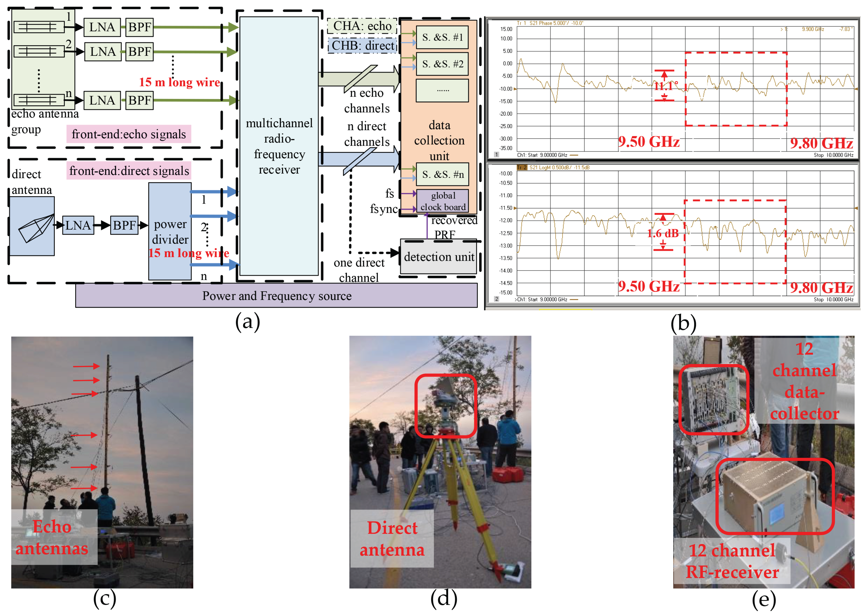
As shown in Figure 2a, the multichannel BiSAR stationary receiver system mainly consists of a power and frequency source unit, a front-end unit, a multichannel RF receiver, a data collection unit and a detection unit. The noncooperative nature of the bistatic system needs a conservative data-acquisition strategy. The data collection unit consists of n Sampling and Storage (S.&S.) boards and a global clock board. Considering that the data collection unit is not suitable for high-rate continuous recording (e.g., 1.0 GS/s for each (S.&S.) board), the scheme of interrupted acquisition can be employed. In such a scheme, a detection board is used for generating the sampling gates. The signal received from the horn antenna is divided into (n + 1) channels, with one fed into the detection unit and other channels fed into the data collection unit. Reliable triggering requires the voltage of the direct signals to be larger than a certain level, which is determined by the I/O voltage requirement of the Field Programmable Gate Array (FPGA) detection board. However, considering the atmosphere effect and the accuracy of the direct antenna steering, the estimation error of the power of the direct signal is about ±2 dBm. Therefore, a conservative detection method requires that the gain should be set as a properly large value to decrease the lost rate of records. The system is activated minutes before the transmitter fires. The sampling window is generated by the detection unit and kept for a proper time to record signals for each PRF. It is important to note that direct-path signal leakage through the side and back lobes of the scattered path antennas can be an error source depending on the transmitted pulse length; however, we get rid of most of the leakage by range compression.
As is shown in Figure 2a, the multichannel time synchronization is a design driver for the stationary receiver system. Each S.&S. board has two channels (i.e., Channel A (CHA) to receive the backscattered signal and Channel B (CHB) to receive the direct signal), which use the same Analog/Digital (AD) module. This implies that the board has a good performance of in-board synchronization, while the problem of the synchronization among the n boards needs to be addressed. Therefore, the received direct signal can be split into (n + 1) signals to calibrate the random jitters among different boards. However, this strategy inevitably introduces various delays from the antennas to the boards in the data collector, which also needs to be compensated.
Additionally, one of the non-ideal factors in hardware implementation is presented in Figure 2b. The phase-frequency and amplitude-frequency response of the cable measured by a Vector Network Analyzer (VNA) is presented, and the flatness in the band is about 1.6 dB. As is mentioned above, these factors will impact the phase errors and relative gains of the signal paths.

2.2. Signal Model

2.2.1. Phase Error

For BiSAR radars, the transmitted signal can be modeled as:
S ( t ) = c o s [ 2 π f T t + π K t 2 + φ T ( t ) ] , - T r / 2 < t < T r / 2
where f T , K, φ T ( · ) and T r denote the expected value of carrier frequency, the chirp rate, the phase error of the transmitter and the pulse duration time, respectively. After the propagation delay, the received signal is:
S ( t - τ ) = c o s [ 2 π f T ( t - τ ) + π K ( t - τ ) 2 + φ T ( t - τ ) ] , - T r / 2 < t - τ < T r / 2
where τ is the propagation delay time of the radar pulse.
The signal generated by the local mix oscillator can be written as:
S o ( t ) = c o s ( 2 π f m t + φ R ( t ) )
where f m is the expected frequency of local oscillator and φ R ( · ) is the phase error of the receiver.
Here, the frequency up-conversion and down-conversion factors are simplified for derivation. After down-conversion operation, the form of the received real Intermediate-Frequency (IF) signal can be derived as [5]:
S c ( t ) = c o s [ 2 π f c t - 2 π f T τ + π K ( t - τ ) 2 + φ T ( t - τ ) - φ R ( t ) ] , - T r / 2 < t - τ < T r / 2
where f c = f T - f R .
As shown in Equation (4), in a bistatic radar system, the phase error of two oscillators has to be considered. According to [21,22], an equivalent model is to assume that the first one has an ideal behavior and to assign the combined phase error to the second one. Considering that τ is small within the same PRF interval, we can assume φ T ( t - τ ) φ T ( t ) . Therefore, the last two terms in Equation (4) can be denoted as the time-varying bistatic oscillator phase error Φ ( t ) and be modeled as:
Φ ( t ) = 2 π Δ f 0 t + ϕ s t ( t ) + ϕ r w ( t )
where Δ f 0 indicates a combined error in the nominal frequency of the oscillators, ϕ s t ( t ) represents a zero-mean stationary process and ϕ r w ( t ) stands for a non-stationary random walk [21,22].

2.2.2. Signal Model

Considering the radiation pattern of receiver/transmitter and azimuth time η, the ideal baseband complex form of the direct signal is derived as:
S D ( t , η ) = A 0 W r ( t - R D ( η ) c ) W a t ( l s ( η ) , l A ) W a r ( l s ( η ) , l A ) ) exp { - j 2 π f T R D ( η ) c } × exp { j π K ( t - R D ( η ) c ) 2 } , t [ R D ( η ) c - T r / 2 , R D ( η ) c - T r / 2 + T d ]
where W r ( · ) , W a t ( · ) , W a r ( · ) are the envelope of the signal, the radiation pattern of the transmitter and the direct path receiver, η is the azimuth time, A 0 is the amplitude of the signal, R D ( η ) is the distance from the satellite to the direct antenna, l s ( η ) and l A are the locations of the satellite and the synchronization receiver, c is the speed of light and T d is the minimum duration of the acquisition given by the effective azimuth real aperture of the radar illumination and can be evaluated using the location parameters.
Based on Equation (6), We can take several factors into consideration, namely the bistatic phase error introduced by the oscillator, the jitter and delay introduced by multiple channels and the triggering delay introduced by the detection mechanism. Therefore, the direct signals S D i ( t , η ) , which are received by the CHB of board i and then converted to baseband, can be derived as:
S D i ( t , η ) = W D exp [ - j 2 π f T ( R D ( η ) c + ε d ( i ) + ε j ( i ) ) + j π K ( t - ( R D ( η ) c + ε d ( i ) + ε j ( i ) ) ) 2 ] exp [ j Φ ( t , η ) ] , t [ R D ( η ) c + ε ( i ) - T r / 2 , R D ( η ) c + ε ( i ) - T r / 2 + T d ]
where ε ( i ) = ε d ( i ) + ε j ( i ) + ε t r ( η ) , ε d ( i ) is the path delay from the direct antenna to the data collector, ε j ( i ) is the jitter for board i ( = 1 , 2 , . . . , n ) , ε t r ( η ) is the trigger delay and W D is the combined direct-path term related to the amplitude and radiation pattern terms and is simplified to emphasize the phase terms.
W D = A 0 W r [ t - ( R D ( η ) c + ε d ( i ) + ε j ( i ) ) ] W a t ( l s ( η ) , l A ) W a r ( l s ( η ) , l A )
Similarly, the echo signals S B i ( t , η ) , which are received by the CHA of board i and then converted to baseband, can be written as:
S B i ( t , η ) = W B i exp [ - j 2 π f T ( R B ( η ) c + ε e ( i ) + ε j ( i ) ) + j π K ( t - ( R B ( η ) c + ε e ( i ) + ε j ( i ) ) ) 2 ] exp { j Φ ( t , η ) } , t [ R D ( η ) c + ε ( i ) - T r / 2 , R D ( η ) c + ε ( i ) - T r / 2 + T d ]
where ε e ( i ) is the path delay from the scattered-path antenna to the data collector, l T is the location of the scene target, R B ( η ) is the path of the echo signal for the radar range from the transmit antenna to an observed point plus the radar range from the observed point to the receive antenna and W B i is the combined two-dimensional envelop, which can be written as,
W B i = A 1 W r [ t - ( R B ( η ) c + ε e ( i ) + ε j ( i ) ) ] W a t ( l s ( η ) , l T ) W b i ( l s ( η ) , l A ) )
where A 1 is the amplitude of the echo signal determined by several factors, like incident power density and the scattered path antenna areas, and W b i ( · ) is the radiation pattern of the echo antenna.

3. Integrated Synchronization Strategy

This section provides details on the synchronization strategy, aiming for the reduction of phase error and the improvement of signal quality. The time synchronization will be introduced first, which includes three aspects: PRF generation under noisy conditions, multichannel calibration and the alignment of the recorded data with the orbital data. Afterward, the phase synchronization strategy, the key part of this paper, will be depicted.

3.1. Time Synchronization

3.1.1. PRF Generation under Noisy Conditions

The basic idea of the time synchronization strategy originates from the ideas proposed in [40]. The real-time detection, which can avoid the accumulation of sampling window time offsets caused by the frequency deviation, is introduced for PRF recovery. To avoid the accumulation of sampling window time offsets caused by the frequency deviation, a methodis introduced for PRF recovery. An important requirement of the detection method is that it can be implemented in the noisy environment, especially in the case when the power of the noise is larger than that of the signal. Moreover, considering both the complexity and performance, the proposed detection method should be suitable for our experimental configuration.
From the perspective of performance, although the method based on a matched filter can yield the best result, it consumes too much computational resources for the FPGA module. Therefore, considering the characteristics of chirp signal, an efficient method is employed, which is also realized in the frequency domain. It can satisfy the requirements of the BiSAR configuration, and it has a good performance under noisy conditions. The scheme of the detection is depicted in Figure 3. An efficient implementation can be realized in the frequency domain considering the characteristics of chirp signal. As is depicted in Figure 3. The IF signal is processed by the FPGA detection board, which includes the real-time FFT, the rectangle interception, the comparator and the Digital Phase Locked Loop (DPLL) [36]. We apply the real-time N-point FFT on the received IF signal. Only the peak value instead of the average power in the frequency domain is employed for PRF generation. If the peak value in the frequency domain is larger than the preset value, the module of DPLL will hold for a fixed time to ensure that the frame of the signal if fully sampled.
The basic principle for the real-time detection is described here. The basic principle for why the real-time detection can scale SNR in the frequency domain is described here. We can denote the noised direct signal as S ( n ) , the FFT of S ( n ) with an N-point rectangle window as S ( k ) and the SNR of the amplitude in the time domain and the frequency domain as α 0 and α 1 , respectively. For the windowed signal, α 1 has a relationship with α 0 , i.e.,
α 1 = C × N × α 0 , 1 N 1 T s K
where C is assumed to be a constant when 1 N 1 T s K and T s is the sampling period. The constant C can be calculated by using the parameters of the signal and the noise.
The condition shown in Equation (11) considers the characteristic of chirp signals in the frequency domain: the maximum value in the frequency domain increases along with N when the following expression is satisfied:
f s N N × T s × K
Equation (11) implies that the SNR in the frequency domain is scaled by a factor related to N. Benefiting from the scaling effect in the transform domain, the detection method in the frequency domain has the capability to detect the chirp signal even at a low SNR.
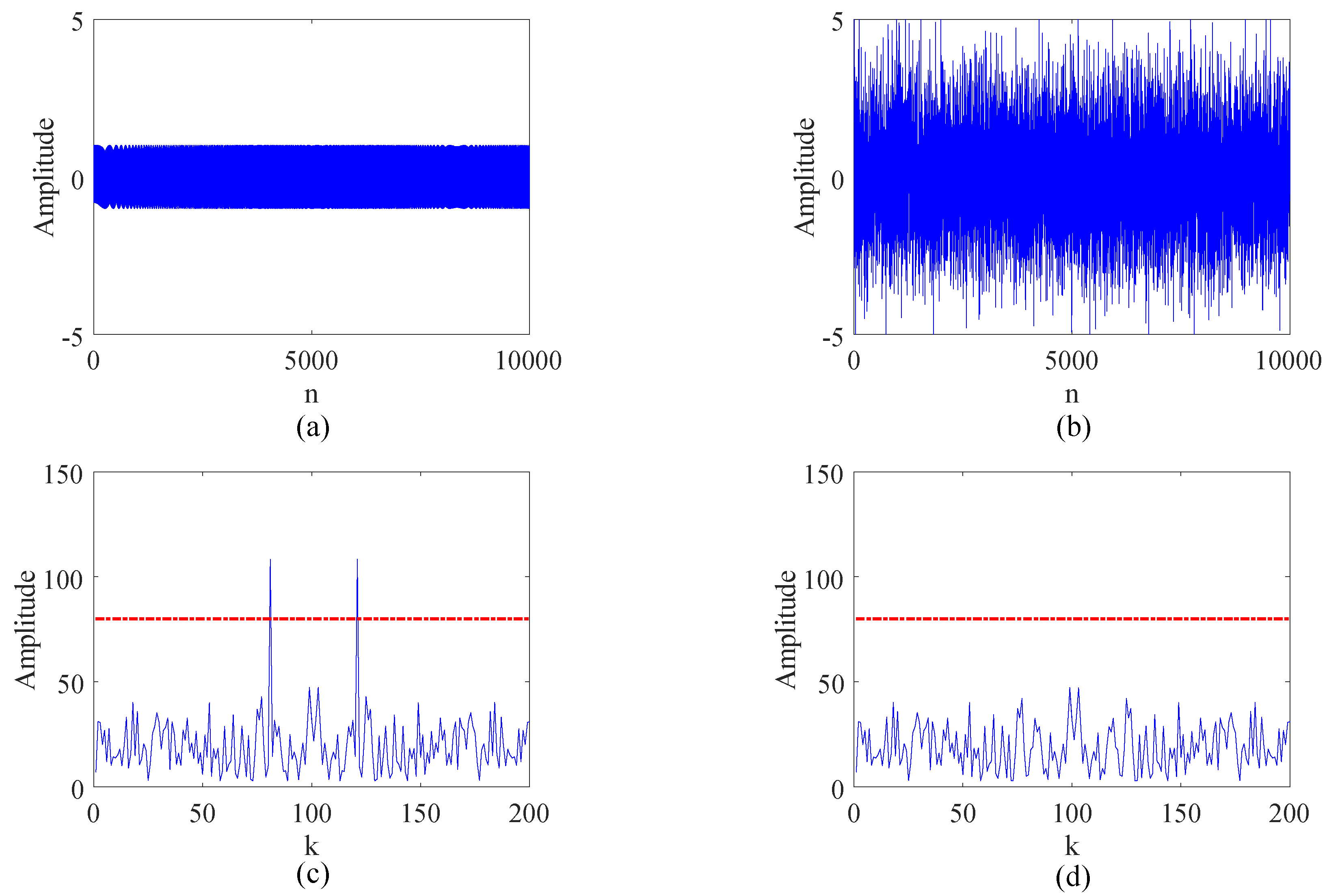
A simple simulation is demonstrated in Figure 4. The power of the noise is about 25-times that of the chirp signal, which makes it difficult to detect the signal in the time domain. The chirp signal and noise are shown in Figure 4a,b, respectively. Taking a small number of samples (N = 200) of the noised chirp or noise, the DFT of them is shown in Figure 4c,d, respectively. According to the preset threshold, the signal is accurately detected. Compared to the timing-detection method and the matched filter method, the main advantage of this detection method is that it has a satisfactory performance under a noisy condition and also a simple implementation using the FPGA module.

3.1.2. Multichannel Calibration

Similar to any multichannel system, it is necessary to estimate and compensate the delay and jitter for all channels. For multichannel applications, multichannel calibration is a necessary step to keep the precision of the processed results. As shown in Figure 2a, the multichannel system mainly consists of five units. The delay and jitter for different RF and digital paths needs to be considered. On the one hand, the digital channels on the data collector are synchronized by splitting up the direct signal into six channels. On the other hand, distributing the direct signal after the multichannel RF receiver additionally introduces the different path delays and jitters between Channel 1 and other RF channels, which can be viewed as a compromise to satisfy the different power requirement for triggering and sampling. In summary, using the correlations of the six sampled direct signals, the delay and jitter can be estimated and compensated.
The delay parameters, i.e., ε d ( i ) and ε e ( i ) shown in Equations (7) and (9), can be calibrated precisely before the experiment under the same condition. In contrast, ε j ( i ) varies for every PRF generation and is not deterministic. Therefore, taking the expected value of ε d ( 1 ) as the reference, the scattered-path channel cross-correlation is performed between signals received by the first board and all other boards:
C d , j ( τ ; η ) = - + S D j ( t , η ) S D 1 * ( t - τ , η ) d t = exp { j 2 π f T ( ε ( 1 ) ( η ) - ε ( j ) ( η ) ) } × - + exp { j π K ( t - ( ε ( j ) ( η ) ) ) 2 - j π K ( t - τ - ε ( 1 ) ( η ) ) 2 } d τ , j = 2 , 3 , . . . , n
Since the maximum of C d , j ( τ ; η ) arrives when τ ( η ) = ε ( 1 ) ( η ) - ε ( j ) ( η ) , the estimation of τ ( η ) , i.e., τ ^ ( η ) , can be obtained. Finally, the estimation of ε ( j ) can be calculated as ε ( j ) ε d ^ ( 1 ) - τ ^ ( η ) .

3.1.3. Alignment of the Recorded Data with the Orbital Data

Temporal alignment of the acquired data with the transmitter orbit and the Doppler centroid estimation is very important, and some discussions are provided in [9]. Although the misestimation of the zero Doppler time has no significant blurring of the image results, the misalignment caused by the recorded data loss will result in the decorrelation for azimuth focusing. The temporal alignment of the recorded data with the orbital data, which is called lost data compensation, is necessary.
The auxiliary information, like the sampling time t i for each record i, is used to address the problem. We can calculate the number of lost records N i by:
N i = r o u n d ( Δ t i / δ t - 1 ) , i = 1 , 2 , . . . . , N r e c
where δ t is the expectation of the normal sampling intervals, N r e c is the total number of the records and the adjacent sampling time interval Δ t i can be evaluated by:
Δ t i = t i + 1 - t i , i = 1 , 2 , . . . . , N r e c - 1
Then, the N i records for the corresponding orbit position can be zero-padded.

3.2. Phase Synchronization

As is introduced in Section 1, the phase synchronization strategy based on the direct signal mainly contains two basic ideas. In addition to phase error estimation and compensation from RCM, an alternative is to straightforwardly cancel out the error instead of estimation. A key mathematical argument leading to the second one is that the direct and echo signals approximately share the same initial phase and the same phase error, as is demonstrated in Equations (7) and (9).
Here, a brief derivation is given. Taking the direct signal as the matched filter and ignoring the amplitude term, the range compression operation can be written as:
S o u t i ( t , η ) = - + S B i ( τ , η ) S D i * ( τ - t , η ) d τ
where S B i ( · ) and S D i ( · ) are the echo and direct signals, respectively. For simplicity, we denote τ D = R D ( η ; l A ) / c , τ B = R B ( η ; l T ) / c and Δ ε ( i ) = ε e ( i ) - ε d ( i ) .
Substituting the concrete form in Equation (16) yields the peak value of range compression,
S o u t ( t , η ) | t = τ B - τ D + Δ ε ( i ) exp ( - j 2 π f T ( τ B - τ D + Δ ε ( i ) ) )
In Equation (17), the variations of the phase error over times smaller than the Pulse Repetition Interval (PRI) can be ignored considering the coherence of radars. Moreover, it has been shown that the delay difference Δ ε ( i ) can be obtained in advance. After the compensation of exp ( j 2 π f T Δ ε ( i ) ) , the complete form of Equation (17) is:
S o u t ( t , η ) | t = τ B - τ D + Δ ε ( i ) = δ ( l T ) W s ( x S , x A , l T ) s i n c ( t - δ R ( η ; l T ) / c ) × exp ( - j 2 π f T δ R ( η ; l T ) / c )
where δ ( l T ) is the energy of the signal after range compression, δ R ( η ; l T ) = R B ( η ; l T ) - R D ( η ; l A ) and W s ( l s , l A , l T ) is the synthesis result of the transmitter’s and the receiver’s antenna radiation pattern.
Note that the derivation is effective only when the signals are of high SNR. If this condition cannot be satisfied, it is necessary to reconstruct the degraded signals by introducing a signal with satisfactory SNR (called r e f e r e n c e   s i g n a l ). By correlation operations, the information distinction between r e f e r e n c e   s i g n a l and all other signals can be obtained as:
C ( τ , η ) = - + S D ( t , η ) S r e f * ( t - τ , η 0 ) d t = - + exp ( - j 2 π f T ( R D ( η ) - R r e f ( η 0 ) ) / c ) exp ( j π K ( ( t - R D ( η ) ) / c ) 2 - ( t - τ - R r e f ( η 0 ) / c ) 2 ) ) × exp ( 2 π Δ f 0 t + ϕ s t ( t ) + ϕ r w ( t ) - ϕ s t ( t - τ ) - ϕ r w ( t - τ ) ) d τ
where S r e f ( t , η 0 ) denotes the r e f e r e n c e   s i g n a l on PRF time η 0 . For the sake of simplicity, the subscript i is removed from the derivation. As can be seen from Equation (19), the maximum of C ( τ , η ) arrives when the centers are aligning, namely, τ m a x = ( R D ( η ) - R r e f ( η 0 ) ) / c .
Thus, the phase of the peak is given by:
Ψ ( τ m a x ) = - 2 π f T τ m a x + 2 π Δ f 0 τ m a x + ϕ e r r
where ϕ e r r denotes the combined error of the terms shown in Equation (17).
Therefore, the reconstructed direct signals can be written as:
S ^ D ( t , η ) = S r e f ( t - τ m a x , η 0 ) × exp ( j Ψ ( τ m a x ) )
In Equation (21), the offset values τ m a x need to be estimated. However, considering that the detection is influenced by random factors, such as the stability of the oscillator, the system delay of the different channels, the precision of the A/D and the clock precision of the FPGA, it is difficult to obtain the precise τ m a x by using the geometric information. Therefore, the estimate of τ m a x , i.e., τ ^ m a x , can be obtained by a correlation operation. Then, the phase of the peak is given by:
Ψ ( τ ^ m a x ) = - 2 π f T τ ^ m a x + 2 π Δ f τ ^ m a x + ϕ e r r
Thus, the reconstructed signals can be written as:
S ^ D ( t , η ) = S r e f ( t - τ ^ m a x , η 0 ) · exp ( j Ψ ( τ ^ m a x ) )
From Equation (23), it can be seen that the reconstructed direct signals S ^ D ( t , η ) carry all necessary information of the direct signals S D ( t , η ) on azimuth time.
The r e f e r e n c e   s i g n a l can be selected from the recorded data or it can be created by the joint use of a priori information and the real signal (called n e w   r e f e r e n c e   s i g n a l ). The choice depends on whether the quality of r e f e r e n c e   s i g n a l is satisfactory, which will be depicted in Section 3.3.

3.3. Integrated Process Flow

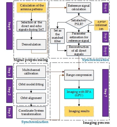
The integrated process flowchart of the synchronization strategy is shown in Figure 5.
Step 0:
Signal preprocessing. Calculate the direct and echo antenna patterns; select the direct and echo signals during SAT; and perform demodulation operations.
Step 1:
Multichannel calibration. Correlate the signals of all other boards (2∼n) with the signals of Board 1 on each PRF time, and compensate the delay and jitter errors for signals of all other boards.
Step 2:
Orbit model fitting and aligning the recorded data with the orbital data (orbit alignment).
Step 3:
Coordinate system transformation. The location of the orbit and the synchronization and echo receivers are transformed into the BiSAR coordinate system [38].
Step 4:
Selecting the reference signal from the signals through calculation. If the Peak Side Lobe Ratio (PSLR) of the reference signal meets the requirements of - 13 dB, go to Step 6; else, go to Step 5.
Step 5:
Estimating parameters for the reference signal. The parameters are linear frequency modulation rate, delay time and linear phase offset, respectively.
Step 6:
Reconstruction of all direct signals. Employ the reference signal or new reference signal to reconstruct all signals during SAT with a shift and phase compensation operation.
Step 7:
Imaging process. After range compression, the imaging algorithm can be accelerated by the Graphics Processing Unit (GPU).
The requirement of “−13 dB” shown in Step 4 is set due to the fact that the PSLR of self-match filtering is an important indicator related to the signal quality. As we know, “−13.3 dB” is the PSLR of the ideal signal after compression. As regards the practical signals, “−13 dB” is chosen as a feasible requirement for the signal, since it corresponds to relatively high SNR. Note that values around “−13 dB” can be chosen according to the quality of the practical signal.
Considering the pulse duration time for every PRF is of the order of 10 μ s, e.g., 50 μ s, the estimation of Equation (7) can be written as:
S ( t , η ) = exp ( j π K ^ ( t - τ ^ ) 2 + j 2 π Δ f ^ 0 t + j ϕ ^ s y n )
where K ^ , τ ^ , Δ f ^ 0 and ϕ ^ s y n are the estimations of the linear frequency rate, the delay time of system, the synthetic linear frequency offset and all synthetic phase, respectively.
It is far more challenging to estimate parameters for every direct signal during SAT, for separating the part contributed by range history. Thus, our strategy is estimating the parameters only for the specific azimuth time, which implies that the processing complexity is well reduced. The parameters can be estimated by using heuristics, and the assessment is based on the criteria of maximum likelihood.
Taking the reference signal or the new reference signal as the matched filter, the results of range compression for all other direct signals can be used to determine whether estimation is precise. Specifically, the estimation is assumed to be precise if they have the same peak position, and the expectation of the maximum difference of the angle of the peak is less than the threshold (e.g., 5 × 10 - 2 rad). The threshold comes from the precision requirement of interferometry. In fact, the decorrelation introduced by this processing step is expected to be as small as possible. The coherent coefficient of 0.99 implies the interferometric phase error of 0.19 rad, which can be satisfied by the given threshold.

4. Experimental Results

The experiments using TerraSAR-X and a ground receiver system are carried out on the mountain and urban areas of Beijing. The experimental parameters are shown in Table 1. In this experiment, we are interested in the amplitude of the antenna’s radiation pattern of the direct and the echo channels in the illuminated time. Note that the phase response is considered constant across the main lobe of the pattern; hence, it can be ignored.
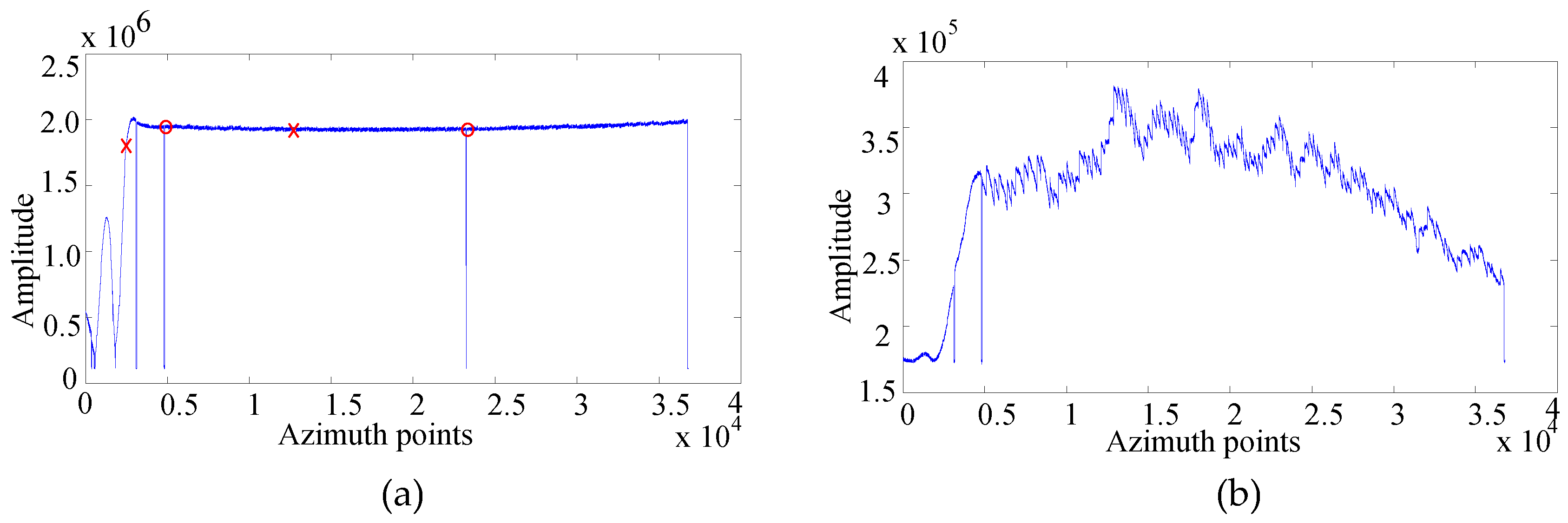
As shown in Figure 6a, the amplitude of the main lobe of the direct channel tends to be flat, which is caused by the characteristics of saturation and needs to be compensated. The echo signal is guaranteed to be unsaturated as shown in Figure 6b. As mentioned above, the SNR of the direct signals, marked as X in Figure 6a, varies with azimuth time.
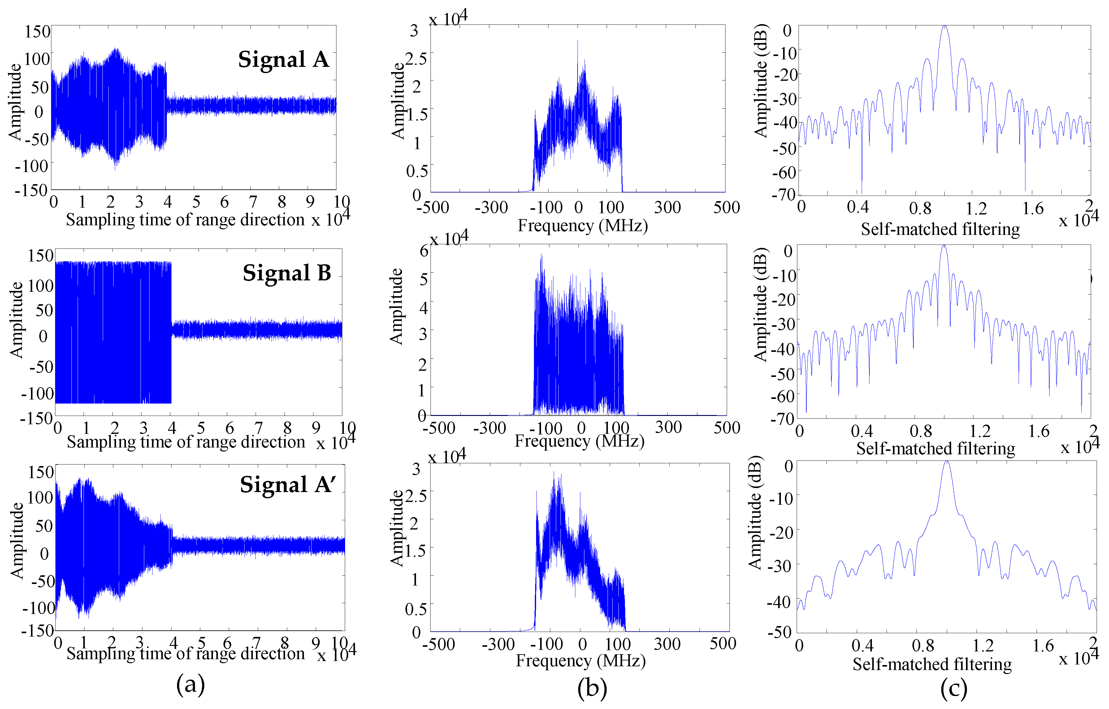
Now, we will discuss the unsaturated signal A, the saturated signal B and the signal A’ of low SNR, respectively, which can be encountered in different cases. Signal A is the expected signal, which is the most common one. Signal B is the saturated version of signal A, which may be introduced by the inaccurate estimation of the power of the arriving direct signal or the inaccurate estimation of relative gains of the signal paths for the ground receiving system. Signal A’ is the signal of low SNR, which may be caused by non-ideal factors of the hardware implementation.
The unsaturated signal A, saturated signal B and signal A’ with the ramp-modulation effect are presented in Figure 7a, respectively. The ramp-modulation effect means that signal A’ has a linear modulation on its amplitude. Their corresponding characteristics including baseband frequency spectrum, and self-matched filtering results are shown in Figure 7b,c, respectively.
As shown in Figure 7b,c, the unsaturated signal A is of high SNR, and its PSLR value is −13.71 dB. In this case, our strategy can directly reconstruct the direct signals using Equation (23) by taking signal A as the matched filter.
Compared to the former signal A, the saturated signal B on main lobe time has the frequency leakage effect, and its PSLR value is −11.7 dB. The frequency leakage effect means that the energy of the signal distributes on the spectrum because of saturation. The unsaturated signal A’ has the ramp-modulation effect in its frequency spectrum, and its PSLR value is −15.89 dB. The signals B and A’ are of low SNR, which is caused by the non-ideal hardware implementation. Therefore, if the signals B and A’ are directly taken as the matched filters, the quality of signals will deteriorate the image quality.
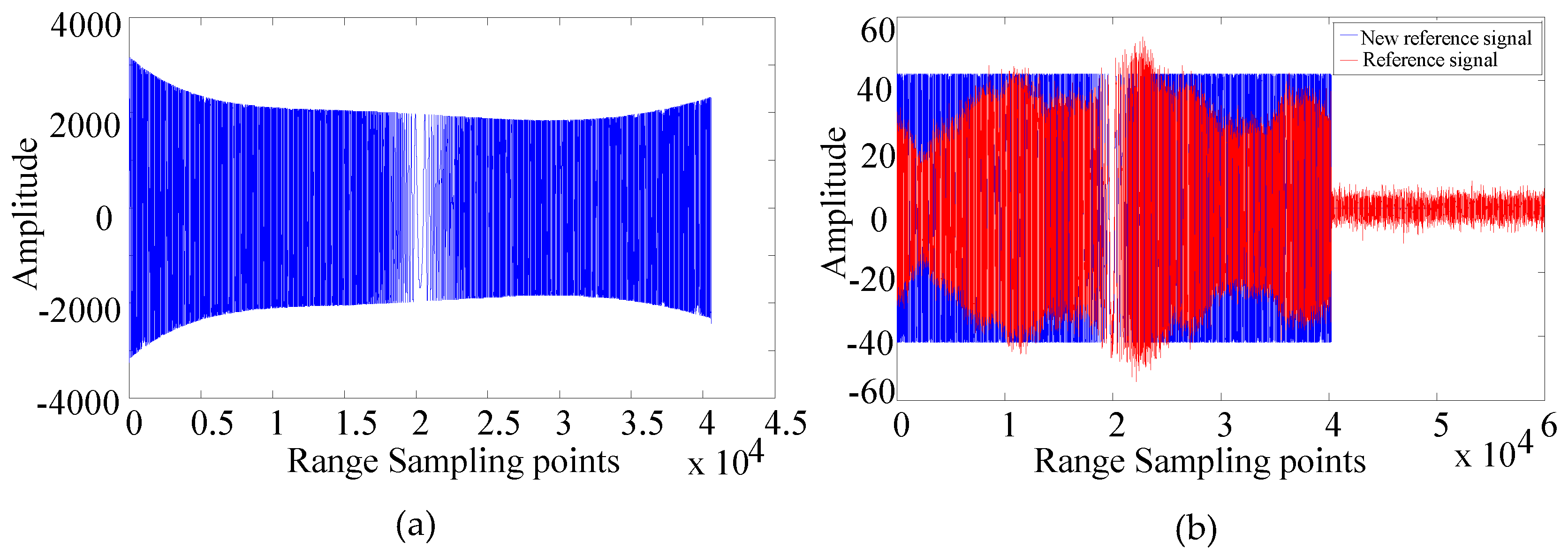
As discussed in Section 3.3, our generalized strategy is first to reconstruct a new reference signal followed by the reconstruction of all other direct signals. Using a priori information shown in Figure 8a, i.e., the parameters of chirp provided by TerraSAR-X, the parameters listed in Equation (24), such as K ^ , τ ^ , Δ f ^ 0 and ϕ ^ s y n , can be precisely estimated. The real parts of reference signal and new reference signal are shown in Figure 8b. The n e w   r e f e r e n c e   s i g n a l is employed for the reconstructions of all other direct signals.
Final imaging results are obtained using BPA accelerated by the GPU. If raw data and scene partitioning are optimized, the efficiency can be improved. Roughly, the focusing process for a 12,288 × 16,384 SAR image in staring spotlight mode consumes about five days by the CPU (intel Xeon E5620) and about two hours by the GPU (Nvidia Tesla K20c).
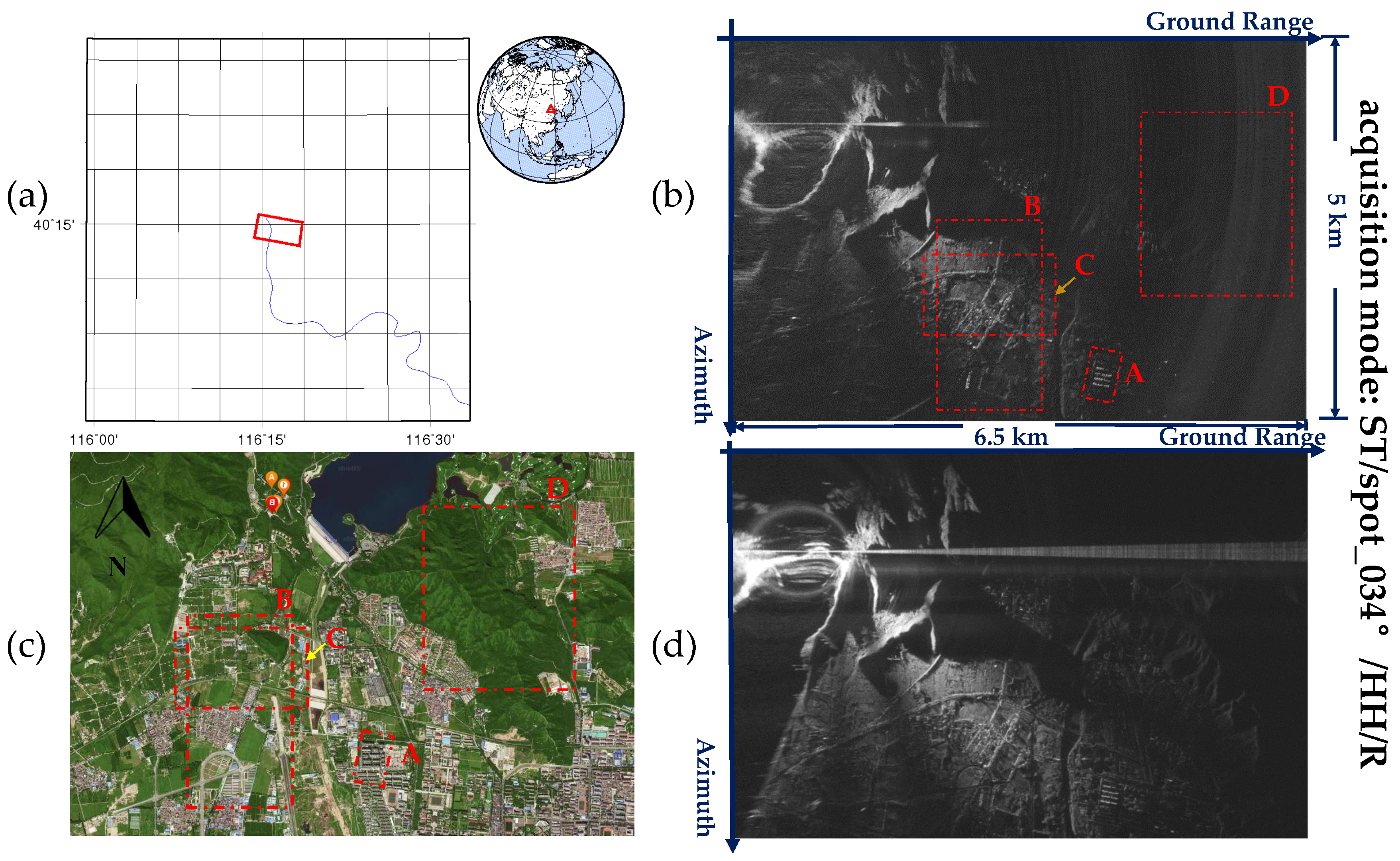
The comparison of the optical image; the uncompensated and compensated BiSAR images are shown in Figure 9. As described in Section 1, considering the deteriorative factors in the BiSAR configuration, some undesirable features have appeared in the obtained images. In order to resolve this problem, the integrated synchronization strategy is employed. For convenience, the improvement of the image quality is explained through several regions of interest, including buildings (A), roads (B), vegetation (C) and mountains (D), as shown in Figure 9. Note that the bright line at the reference azimuth position in Figure 9d is generated by the direct-path signal leakage through the side and back lobes of the scattered path antennas. In our acquisition geometry most of the received signal is overlapping with the direct one, since the pulse length is much longer than the additional bistatic range delay. We can get rid of most of it by range compression. Since the SNR is improved, it can be seen that the residue effect is more obvious in Figure 9d than that in Figure 9b.
To better evaluate the performance of the strategy, the comparison of the uncompensated images (left), the compensated images (middle) and the optical images (right) with details of the illuminated areas (A-D) is demonstrated in Figure 10a–d. It can be seen that the zoomed images of A, B, C, and D show more details of these areas. Firstly, as is shown in the left part of Figure 10a, the buildings highlighted by a yellow box have significant defocusing effects in the azimuth, which is caused by the uncompensated phase errors. With the proposed time and phase synchronization strategy, the phase errors are removed, and the image is refocused in the azimuth dimension. The effectiveness of the strategy can also be verified by the comparison of other buildings below the marked area. These buildings can be identified in the compensated image, but not in the uncompensated one. The improvement of SNR is illustrated in Figure 10b. The uncompensated image is severely contaminated by the noise, making it difficult to identify the roads (marked by a red arrow). By contrast, the compensated image has provided more details. Furthermore, Figure 10c shows that significant positioning errors along the scene extension are introduced in the uncompensated image. The positioning errors are confirmed with the reference of a dashed horizontal line. Finally, it can be seen that significant “noise”, which seems like a fringe, appears in the left part of Figure 10d. The fringes, which are highlighted with the red arrows, are formed by the sidelobes of the unfocused transmitter’s direct signals. Owing to the illumination by the sidelobe of the antennas, the difference between the compensated and uncompensated images can be easily analyzed. The dam area, which is enclosed by the yellow box, is almost invisible in the uncompensated image, since it is contaminated by the “noise”. In contrast, the compensated image retains good quality and is very clear to identify. To illustrate the noise more clearly, the mountain area enclosed by the green box is also used for demonstration. It can be seen that the large “noise” makes it difficult to identify the targets in the green box without compensation. However, in the compensated image, much information of the scene is shown. The comparisons directly prove the effectiveness of the strategy.
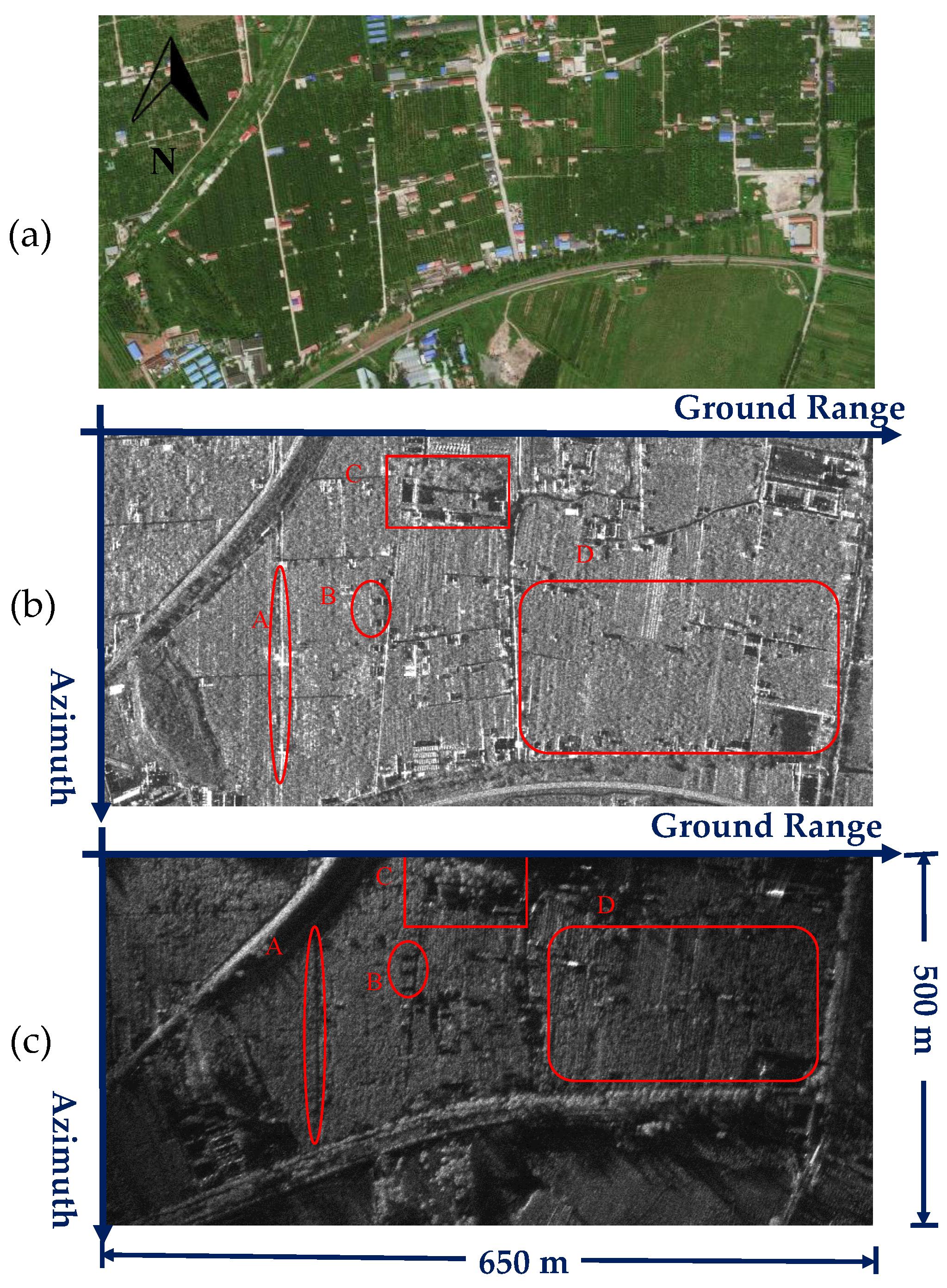
Additionally, a comparison of the optical image, the MonoSAR image, and the BiSAR image is presented in Figure 11a–c to demonstrate different scattering characteristics of different configurations. For example, the area containing road (A) and the area containing three houses (B) are bright in the MonoSAR image (Figure 11b), but dark in the BiSAR image (Figure 11c). On the contrary, the area of trees (C) is clearer in the BiSAR image (Figure 11c) than the one in the MonoSAR image (Figure 11b). Moreover, the textual features in large vegetation (D) are clear in the BiSAR image, partially because the distance from the scene to the receiver is close. Therefore, BiSAR images can be seen as a useful supplement to MonoSAR images.

5. Conclusions

In order to address the problem of synchronization and image quality deterioration in the multichannel BiSAR system, an integrated time and phase synchronization strategy has been presented.
The strategy has been separated into two interrelated parts: time synchronization and phase synchronization. The time synchronization contains three aspects: Firstly, the real-time detection was employed to generate PRF efficiently even in the presence of a high noise level. Moreover, multichannel calibration was performed for the multichannel BiSAR system. Furthermore, the orbital data were well aligned with the recorded data by the use of auxiliary data to avoid degradation. These three aspects can be viewed as a necessary part of the integrated strategy. On the other hand, the phase synchronization strategy was employed to not only remove the phase errors, but also improve the signal quality. It can be seen as the key part of the integrated strategy. The synchronization strategy avoided complicated estimations and significantly reduced the processing complexity.
The performance of the proposed strategy was tested on experimental datasets. Comparison of the uncompensated and compensated images were made. The improvement of the image quality was explained through several regions of interest, including buildings, road, vegetation and mountains. Results have proven that the synchronization strategy is reliable and effective for the multichannel BiSAR system.

Acknowledgments

This work reported herein was funded jointly by the DLR project (GEO2354), the National Natural Science Funds for Excellent Young Scholar (Grant No.61422113) and the Hundred Talents Program of the Chinese Academy of Sciences. The TerraSAR-X datasets were provided by DLR, Germany. Finally, the authors must thank our team members, Yunfeng Shao, Jiangwen Tang, Lei Guo, Nan Wang, Kunye Wang, Yongqiang Chen, Chengxiang Hao, Pei Wang, Wei Wang, Shuo Zhao, Heng Zhang, Jili Wang, Tuan Zhao and Xiangyu Wang.

Author Contributions

Feng Hong conducted the data analysis and mainly drafted this manuscript. Robert Wang directed the research. Zhimin Zhang conceived of and designed the experiments and gave the initial input. Pingping Lu and Timo Balz have contributed to the revision of this paper and provided insightful comments and suggestions. All authors have read and approved the final manuscript.

Conflicts of Interest

The authors declare no conflict of interest.

Abbreviations

The following abbreviations are used in this manuscript:
BiSARBistatic Synthetic Aperture Radar
SNRSignal to Noise Ratio
BPABack-Projection Algorithm
SATSynthetic Aperture Time
PRIPulse Repetition Interval
PRFPulse Repetition Frequency
FPGAField Programmable Gate Array
LNALow Noise Amplifier
S.&S.Sampling and Storage
CHAChannel A
BiSARBistatic Synthetic Aperture Radar
CHBChannel B
A/DAnalog/Digital
VNAVector Network Analyzer
IFIntermediate-Frequency
BPFBand-Pass Filter
DPLLDigital Phase Locked Loop
PSLRPeak Side Lobe Ratio
GPUGraphics Processing Unit

References

  1. Walterscheid, I.; Espeter, T.; Brenner, A.R.; Klare, J.; Ender, J.H.G.; Nies, H.; Wang, R.; Loffeld, O. Bistatic SAR experiments with PAMIR and TerraSAR-X-setup, processing, and image results. IEEE Trans. Geosci. Remote Sens. 2010, 48, 3268–3279. [Google Scholar] [CrossRef]
  2. Krieger, G.; Moreira, A. Spaceborne bi- and multistatic SAR: Potential and challenges. IET Radar Sonar Navig. 2006, 153, 184–198. [Google Scholar] [CrossRef] [Green Version]
  3. Walterscheid, I.; Klare, J.; Brenner, A.R.; Ender, J.H.G.; Otmar, L. Challenges of a bistatic spaceborne/airborne SAR experiment. In Proceedings of the 8th European Conference on Synthetic Aperture Radar (EUSAR), Dresden, Germany, 16–18 May 2006.
  4. Loffeld, O.; Nies, H.; Peters, V.; Knedlik, S. Models and useful relations for bistatic SAR processing. IEEE Trans. Geosci. Remote Sens. 2004, 42, 2031–2038. [Google Scholar] [CrossRef]
  5. Krieger, G.; Younis, M. Impact of oscillator noise in bistatic and multistatic SAR. IEEE Geosci. Remote Sens. Lett. 2006, 3, 424–428. [Google Scholar] [CrossRef]
  6. Auterman, J.L. Phase stability requirements for a bistatic SAR. In Proceedings of the 1984 IEEE National Radar Conference, Atlanta, GA, USA, 29 February–3 March 1984; pp. 48–52.
  7. Weiß, M. Time and frequency synchronization aspects for bistatic SAR systems. In Proceedings of the 7th European Conference on Synthetic Aperture Radar (EUSAR), Ulm, Germany, 25–27 May 2004; pp. 395–398.
  8. Weiß, M. Synchronisation of bistatic radar systems. In Proceedings of the 2004 IEEE International Geoscience and Remote Sensing Symposium (IGARSS), Anchorage, AK, USA, 20–24 September 2004; pp. 1750–1753.
  9. López-Dekker, P.; Mallorqui, J.J.; Serra-Morales, P.; Sanz-Marcos, J. Phase synchronization and doppler centroid estimation in fixed receiver bistatic SAR systems. IEEE Trans. Geosci. Remote Sens. 2008, 46, 3459–3471. [Google Scholar]
  10. Behner, F.; Reuter, S. HITCHHIKER, Hybrid bistatic high resolution SAR experiment using a stationary receiver and TerraSAR-X transmitter. In Proceedings of the 10th European Conference on Synthetic Aperture Radar (EUSAR), Aachen, Germany, 7–10 June 2010.
  11. Behner, F.; Reuter, S.; Nies, H.; Loffeld, O. Synchronization and Processing in the HITCHHIKER Bistatic SAR Experiment. IEEE J. Sel. Top. Appl. Earth Observ. Remote Sens. 2016, 9, 1028–1035. [Google Scholar] [CrossRef]
  12. Moreira, A.; Krieger, G.; Hajnsek, I.; Hounam, D.; Werner, M.; Riegger, S.; Settelmeyer, E. TanDEM-X: A TerraSAR-X add-on satellite for single-pass SAR interferometry. In Proceedings of the 2004 IEEE International Geoscience and Remote Sensing Symposium (IGARSS), Anchorage, AK, USA, 20–24 September 2004; pp. 1000–1003.
  13. Breit, H.; Younis, M.; Balss, U.; Niedermeier, A.; Grigorov, C.; Hueso-Gonzalez, J.; Fritz, T. Bistatic synchronization and processing of Tandem-X data. In Proceedings of the 2011 IEEE International Geoscience and Remote Sensing Symposium (IGARSS), Vancouver, BC, Canada, 24–29 July 2011.
  14. Eineder, M. Ocillator clock drift compensation in bistatic interferometric SAR. In Proceedings of the 2003 IEEE International Geoscience and Remote Sensing Symposium (IGARSS), Toulouse, France, 21–25 July 2003.
  15. Younis, M.; Metzig, R.; Krieger, G. Performance prediction of a phase synchronization link for bistatic SAR. IEEE Geosci. Remote Sens. Lett. 2006, 3, 429–433. [Google Scholar] [CrossRef]
  16. Younis, M.; Metzig, R.; Krieger, G.; Klein, R. Performance prediction and verification for bistatic SAR synchronization link. In Proceedings of the 6th European Conference on Synthetic Aperture Radar (EUSAR), Dresden, Germany, 16–18 May 2006.
  17. Gierull, C.; Pike, C.; Paquet, F. Mitigation of phase noise in bistatic SAR systems with extremely large synthetic apertures. In Proceedings of the 6th European Conference on Synthetic Aperture Radar (EUSAR), Dresden, Germany, 16–18 May 2006.
  18. Krieger, G.; Moreira, A.; Fiedler, H.; Hajnsek, I.; Werner, M.; Younis, M.; Zink, M. TanDEM-X: A satellite formation for high-resolution SAR interferometry. IEEE Trans. Geosci. Remote Sens. 2007, 45, 3317–3341. [Google Scholar] [CrossRef]
  19. He, Z.; He, F.; Chen, J.; Huang, H.; Dong, Z.; Liang, D. Echo domain phase synchronization algorithm for bistatic SAR in alternating bistatic/ping-pong mode. IEEE Geosci. Remote Sens. Lett. 2012, 9, 604–608. [Google Scholar]
  20. Baumgartner, S.V.; Rodriguez-Cassola, M.; Nottensteiner, A.; Horn, R.; Scheiber, R.; Schwerdt, M.; Krieger, G. Bistatic experiment using TerraSAR-X and DLR’s new F-SAR system. In Proceedings of the 9th European Conference on Synthetic Aperture Radar (EUSAR), Friedrichshafen, Germany, 2–5 June 2008; pp. 57–60.
  21. Rodriguez-Cassola, M.; Baumgartner, S.V.; Krieger, G.; Moreira, A. Bistatic TerraSAR-X/F-SAR Spaceborne-Airborne SAR experiment: Description, data processing, and results. IEEE Trans. Geosci. Remote Sens. 2010, 48, 781–794. [Google Scholar] [CrossRef] [Green Version]
  22. López-Dekker, P.; Mallorqui, J.J.; Serra-Morales, P.; Sanz-Marcos, J. Phase and temporal synchronization in bistatic SAR systems using sources of opportunity. In Proceedings of the 2007 IEEE International Geoscience and Remote Sensing Symposium (IGARSS), Barcelona, Spain, 23–27 July 2007; pp. 97–100.
  23. Wang, W.; Ding, C.; Liang, X. Time and phase synchronization via direct-path signal for bistatic synthetic aperture radar systems. IET Radar Sonar Navig. 2008, 2, 1–11. [Google Scholar] [CrossRef]
  24. Wang, R.; Deng, Y.; Zhang, Z.; Shao, Y.; Hou, J.; Liu, G.; Wu, X. Double-channel bistatic SAR system with spaceborne illuminator for 2-D and 3-D SAR remote sensing. IEEE Trans. Geosci. Remote Sens. 2013, 51, 4496–4507. [Google Scholar] [CrossRef]
  25. Broquetas, A.; Fortes, M.; Siddique, M.A.; Duque, S.; Merlano, J.C.; Lopez-Dekker, P.; MallorquÍ, J.J.; Aguasca, A. Bistatic SAR based on Terrasar-X and ground based receivers. In Proceedings of the 2010 IEEE International Geoscience and Remote Sensing Symposium (IGARSS), Honolulu, HI, USA, 25–30 July 2010; pp. 114–117.
  26. Zeng, T.; Hu, C.; Wu, L.; Liu, F.; Tian, W.; Zhu, M.; Long, T. Extended NLCS algorithm of BiSAR systems with a squinted transmitter and a fixed receiver: Theory and experimental confirmation. IEEE Trans. Geosci. Remote Sens. 2013, 51, 5019–5030. [Google Scholar] [CrossRef]
  27. Walterscheid, I.; Espeter, T.; Gierull, C.; Klare, J.; Brenner, A.R.; Ender, J.H. Results and analysis of hybrid bistatic SAR experiments with spaceborne, airborne and stationary sensors. In Proceedings of the 2009 IEEE International Geoscience and Remote Sensing Symposium (IGARSS), Cape Town, South Africa, 12–17 July 2009.
  28. Nies, H.; Behner, F.; Reuter, S.; Loffeld, O.; Wang, R. SAR Experiments in a bistatic hybrid configuration for generating PolInSAR data with TerraSAR-X illumination. In Proceedings of the 10th European Conference on Synthetic Aperture Radar (EUSAR), Aachen, Germany, 7–10 June 2010.
  29. Sanz-Marcos, J.; López-Dekker, P.; Mallorqui, J.J.; Aguasca, A.; Prats, P. SABRINA: A SAR bistatic receiver for interferometric applications. IEEE Geosci. Remote Sens. Lett. 2007, 4, 307–311. [Google Scholar] [CrossRef]
  30. Zeng, T.; Zhu, M.; Hu, C.; Tian, W.; Long, T. Experimental results and algorithm analysis of DEM generation using bistatic SAR interferometry with stationary receiver. IEEE Trans. Geosci. Remote Sens. 2015, 53, 5835–5852. [Google Scholar] [CrossRef]
  31. Nies, H.; Behner, F.; Reuter, S.; Loffeld, O.; Wang, R. Polarimetric and interferometric applications in a bistatic hybrid SAR mode using Terrasar-X. In Proceedings of the 2010 IEEE International Geoscience and Remote Sensing Symposium (IGARSS), Honolulu, HI, USA, 25–30 July 2010; pp. 110–113.
  32. Duque, S.; López-Dekker, P.; Mallorqui, J.J.; Merlano, J.C. Repeat-pass interferometry using a fixed-receiver and ERS-2/ENVISAT as transmitters of opportunity. In Proceedings of the 2009 IEEE International Geoscience and Remote Sensing Symposium (IGARSS), Cape Town, South Africa, 12–17 July 2009.
  33. Duque, S.; López-Dekker, P.; Merlano, J.C.; Mallorqui, J.J. Bistatic SAR along track interferometry with multiple fixed receivers. In Proceedings of the 2010 IEEE International Geoscience and Remote Sensing Symposium (IGARSS), Honolulu, HI, USA, 25–30 July 2010; pp. 4099–4102.
  34. Duque, S.; López-Dekker, P.; Mallorqui, J.J. Single-pass bistatic SAR interferometry using fixed-receiver configurations: Theory and experimental validation. IEEE Trans. Geosci. Remote Sens. 2010, 48, 2740–2749. [Google Scholar] [CrossRef] [Green Version]
  35. Antoniou, M.; Zeng, Z.; Feifeng, L.; Cherniakov, M. Experimental demonstration of passive BSAR imaging using navigation satellites and a fixed receiver. IEEE Geosci. Remote Sens. Lett. 2012, 9, 477–481. [Google Scholar] [CrossRef]
  36. Wang, R.; Wang, W.; Shao, Y. First bistatic demonstration of digital beamforming in elevation with TerraSAR-X as an illuminator. IEEE Geosci. Remote Sens. Lett. 2016, 54, 842–849. [Google Scholar] [CrossRef]
  37. Hong, F.; Tang, J.; Lu, P. Multichannel DEM reconstruction method based on Markov random fields for bistatic SAR. Sci. China Inf. Sci. 2015, 58, 1–14. [Google Scholar] [CrossRef]
  38. Shao, Y.; Wang, R.; Deng, Y. Error analysis of bistatic SAR imaging and stereoscopy bistatic SAR. IEEE Trans. Geosci. Remote Sens. 2013, 51, 4518–4543. [Google Scholar] [CrossRef]
  39. Zhang, H.; Deng, Y.; Wang, R.; Li, N.; Zhao, S.; Hong, F.; Wu, L.; Loffeld, O. Spaceborne/stationary bistatic SAR imaging with TerraSAR-X as an illuminator in staring-spotlight mode. IEEE Trans. Geosci. Remote Sens. 2016, 99, 1–14. [Google Scholar] [CrossRef]
  40. Espeter, T.; Walterscheid, I.; Gierull, C.; Brenner, A.; Ender, J.; Loffeld, O. Progress of hybrid bistatic SAR: Synchronization experiments and first imaging results. In Proceedings of the 9th European Conference on Synthetic Aperture Radar (EUSAR), Friedrichshafen, Germany, 2–5 June 2008.
Figure 1. Multichannel BiSAR System with TerraSAR-X in staring spotlight mode.
Remotesensing 08 00628 g001
Figure 2. The system structure and the experimental scene. (a) The multichannel BiSAR stationary receiver system; (b) the example of the non-ideal factors: the phase-frequency response (linear delay removed) and amplitude-frequency response of one of the 15 m-long cables (9.50–9.80 GHz); (c) echo antennas; (d) the direct antenna; (e) the twelve-channel data collector and RF receiver.
Remotesensing 08 00628 g002
Figure 3. The flow chart for real-time detection.
Remotesensing 08 00628 g003
Figure 4. Signal detection simulation results. (a) Chirp signal in the time domain; (b) noise in the time domain; (c) maximum S ( k ) of the noisy chirp signal in the frequency domain; (d) maximum amplitude of the noise in the frequency domain. The red line is the preset threshold for detection.
Remotesensing 08 00628 g004
Figure 5. The BiSAR processing flowchart.
Remotesensing 08 00628 g005
Figure 6. Amplitude of antenna radiation pattern of: (a) direct channels; (b) echo channels.
Remotesensing 08 00628 g006
Figure 7. Signal A (without saturation), signal B (with saturation) and signal A’ (without saturation, but with the ramp-modulation effect) on main lobe time. (a) IF direct signal in time domain; (b) frequency spectrum of the complex baseband signal; (c) self-matched filtering result.
Remotesensing 08 00628 g007
Figure 8. Reference signal and new reference signal. (a) I channel of the TerraSAR-X a priori signal (provided by DLR); (b) real part of reference signal (red) and new reference signal (blue).
Remotesensing 08 00628 g008
Figure 9. The images of the interested area: areas marked as A, B, C and D have been highlighted. (a) The location of the illuminated areas (provided by DLR); (b) the uncompensated BiSAR image; (c) optical image (provided by Baidu map); (d) the improved BiSAR image.
Remotesensing 08 00628 g009
Figure 10. Comparison of the uncompensated images (left), the compensated images (middle) and the optical images (right) with details of the illuminated areas (A–D). (a) The zoomed image of A: buildings; (b) the zoomed image of B: roads; (c) the zoomed image of C: vegetation; (d) the zoomed image of D: mountains.
Remotesensing 08 00628 g010
Figure 11. Comparison of: (a) the optical image; (b) the MonoSAR image (provided by DLR); and (c) the compensated BiSAR image.
Remotesensing 08 00628 g011
Table 1. Experimental parameters.
ParameterValue
Carrier frequency9.65 GHz
Signal bandwidth300 MHz
Sampling rate1 GHz
Sampling window length100 μ s
PRF4.85 KHz
SAT6.58 s
Total recorded pulse number36,580