Article

Glu-Co-Assisted Iron-Based Metal–Organic Framework-Derived FeCo/N Co-Doped Carbon Material as Efficient Bifunctional Oxygen Electrocatalysts for Zn–Air Batteries

1
College of Materials Science and Engineering, Qingdao University of Science and Technology, Qingdao 266042, China
2
Shandong Engineering Research Center of Green and High-Value Marine Fine Chemical, Weifang University of Science and Technology, Shouguang 262700, China
3
Department of Physics, Hamline University, St. Paul, MN 55104, USA
*
Author to whom correspondence should be addressed.
Catalysts 2024, 14(3), 205; https://doi.org/10.3390/catal14030205
Submission received: 23 February 2024 / Revised: 15 March 2024 / Accepted: 17 March 2024 / Published: 20 March 2024
(This article belongs to the Section Industrial Catalysis)

Abstract

:
A Zn–air battery serves as an energy storage solution to address fossil energy and environmental concerns. However, sluggish kinetics in oxygen reduction reactions (ORRs) and oxygen evolution reactions (OERs) demand innovative, cost-effective, and stable bifunctional catalysts to replace precious metal catalysts. In this study, an FeCo-CNTs/KB catalyst was synthesized by pyrolyzing NH2-MIL-101(Fe) coated with glu-Co and conductive carbon (KB). This hierarchical structure comprises carbon nanotubes (CNTs) grafted onto a carbon matrix, housing abundant FeCo nanoparticles within the nanotubes or matrix. KB introduction enhances FeCo nanoparticle dispersion and fosters uniform CNT formation with smaller diameters, thus exposing active sites. Consequently, the FeCo-CNTs/KB catalyst exhibits remarkable bifunctional electrocatalytic activity: an ORR half-wave potential of 0.84 V and an OER overpotential of 0.45 V (10 mA cm−2). Furthermore, the FeCo-CNTs/KB catalyst in a secondary Zn–air battery showcases enduring charge–discharge performance (≥300 h).

1. Introduction

Addressing the energy crisis and environmental concerns demands sustainable energy storage and conversion solutions. Rechargeable Zn–air batteries (ZABs) have gained substantial attention for their safety, affordability, and eco-friendliness [1,2,3]. The sluggish kinetics of the oxygen reduction reaction (ORR) and oxygen evolution reaction (OER), which are important electrochemical events throughout the charging–discharging process of ZABs, have restricted the practical applications of ZABs [4,5]. Therefore, catalysts are always employed to improve the kinetic processes of the ORR and OER [6]. Currently, noble metal-based materials, such as Pt for ORR and Ru/Ir for OER, are the most effective commercial catalysts, but their lack of availability, high price, poor stability, and insufficient bifunctional catalytic activity have limited their widespread usage. Therefore, it is essential to design bifunctional catalysts with high catalytic activity, low costs, and good stability for rechargeable Zn–air batteries.
A high specific surface area (SSA) is widely known to expose more active areas for electrocatalysts; meanwhile, the existence of a metal–nitrogen–carbon network can enhance both ORR and OER activities. It was reported that metal particles self-assembled with organic ligands as nodes could exhibit high SSA [7,8], and metal–organic frameworks (MOFs) based on organic ligands are usually used to derive metal–nitrogen–carbon catalysts with high SSAs, which can facilitate active site exposure and electron transfer in electrocatalytic processes [9]. Recently, MOF-derived transition metal–nitrogen–carbon catalysts (M-N-C, M = Fe, Co, Ni) have gained extensive attention as promising bifunctional ORR/OER catalyst alternatives [10,11]. Moreover, diverse nanostructured catalytic materials derived from MOFs have found widespread utility in efficient Zn–air batteries [12,13,14,15]. The synthesis of M-N-C catalysts includes the pyrolysis of transition metal precursors and the carbonization of the carbon framework. Most M-N-C catalysts exhibit a granular appearance due to the self-aggregation of metal during carbonization, contributing to the inadequate utilization of active sites in surface catalytic reactions [16]. Moreover, metal particles on the surface can be corroded during electrochemical reactions, and the decreased nitrogen content attributed to the direct carbonization of MOFs is not conducive to electrocatalysis [17]. The design of hierarchically structured catalysts with metal particles encapsulated in a carbon- or nitrogen-doped carbon layer could prevent their aggregation during carbonization and protect active nanoparticles from corrosion [18,19,20], and nitrogen-doped carbon substrates can modulate active sites and thus enhance ORR and OER performances [21,22]. Pei et al. obtained a hollow-structured FeCo-N-C through the calcination of a ZIF-67 coating with iron [23]. Zhang et al. wrapped a MOF with polydopamine to avoid metal sintering [24]. Furthermore, various reagents such as NH3, urea, and melamine have been adopted as nitrogen sources to enhance nitrogen content [25,26,27]; in particular, melamine has been extensively studied for OERs [28,29,30], which decomposes and assembles with metal atoms to form M-Nx sites during high-temperature carbonization [31,32,33]. The pyrolysis of organic frameworks with nitrogen sources could produce nitrogen-doped carbon with a relatively high nitrogen content [34,35]. In our previous work, glucosamine (glu) was directly utilized to develop a high-performance bifunctional catalyst for ZABs [36], and the wrapping of glu on an MOF precursor would protect metal particles from aggregation during pyrolysis [37,38]. However, the direct pyrolysis of glu or MOF displayed a relatively low yield.
Conductive agents, such as Super-P, acetylene black, Ketjene black (KB), and Denka black, have been introduced into carbon-based materials to effectively improve electrical conductivity and electrocatalytic performance [39,40,41,42]. Moreover, the addition of a conductive agent may also play an important role in yield improvement. KB is a conductive additive with high electrical conductivity and a high specific surface area [43,44,45] that can be used in the synthesis of MOF-derived carbon materials as a conductive agent and a carbon source to improve their performance and product yield. NH2-MIL-101 is an ideal precursor with a high content of nitrogen, highly dispersed iron, and a high SSA [46,47]. In this study, glu-Co-coated NH2-MIL-101 served as a precursor for generating a bifunctional catalyst (FeCo-CNTs/KB), encompassing carbon nanotubes (CNTs) and FeCo nanoparticles through carbonization with melamine and conductive additives (KB) as nitrogen/carbon sources. The glu-Co coating, coupled with the KB addition, can inhibit metal aggregation during high-temperature carbonization by dispersing the NH2-MIL-101 precursors. Additionally, it increased the nitrogen content within the catalyst, enhancing ORR and OER performance. The FeCo-CNTs/KB catalyst exhibited a notable ORR half-wave potential of 0.84 V (vs. RHE) and an OER overpotential of 1.68 V at 10 mA cm−2, highlighting its remarkable bifunctional electrocatalytic capabilities. Incorporating the FeCo-CNTs/KB catalyst into ZABs resulted in exceptional charge–discharge performance, efficiency, and stability.

2. Results

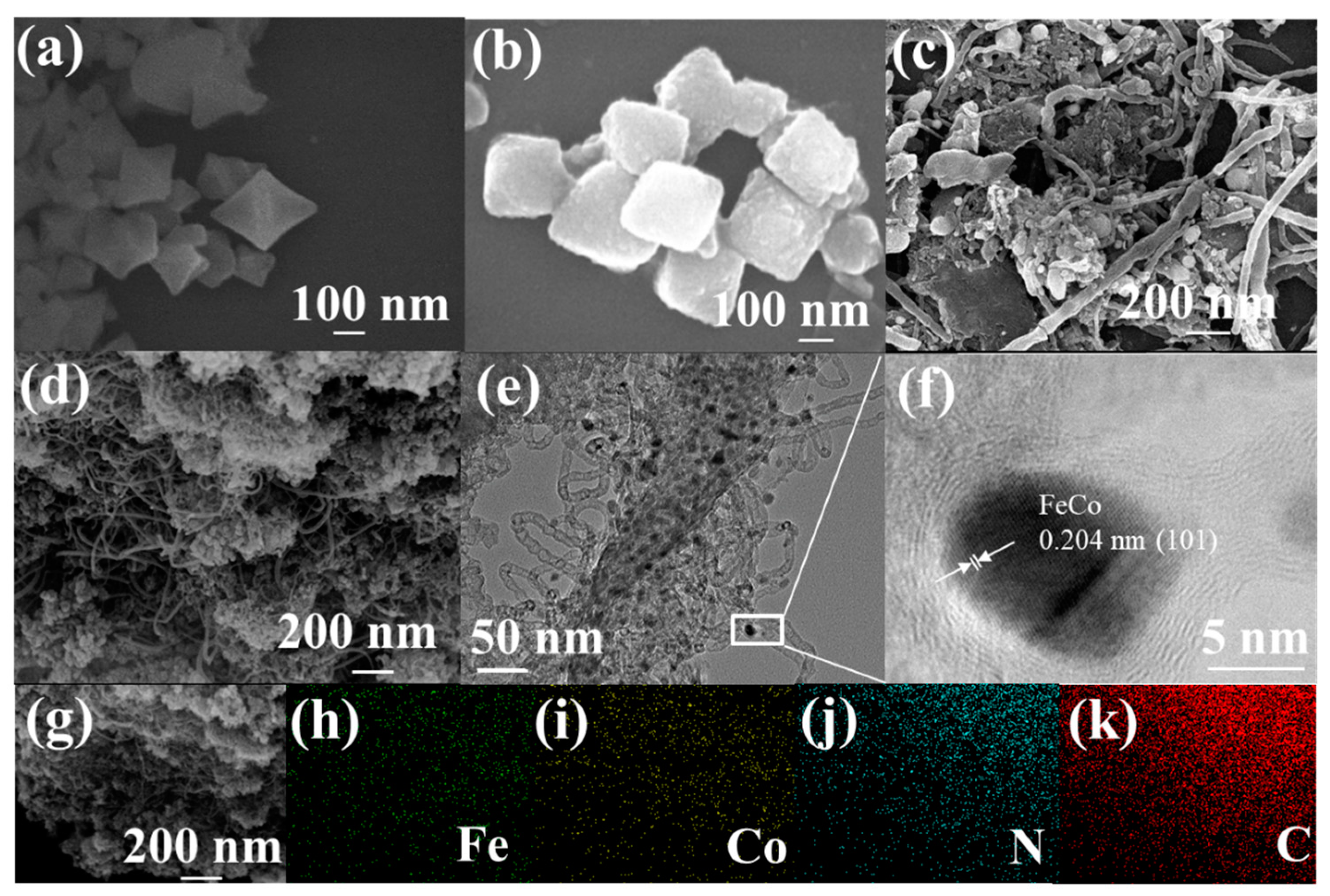
2.1. Structural Characterizations and Composition Analysis

The synthesis process of the FeCo-CNTs/KB catalyst is shown in Scheme 1. NH2-MIL-101(Fe) was prepared through a solvothermal reaction with amino terephthalic acid and ferric trichloride hexahydrate as a ligand and iron source in DMF. Then, NH2-MIL-101(Fe) was used as a substrate to support glu-Co through a simple wet-chemical method with glucosamine hydrochloride and cobalt trichloride hexahydrate. Finally, the obtained NH2-MIL-101(Fe)@glu-Co was employed as the precursor to produce a FeCo-CNTs/KB catalyst through a two-step pyrolysis process with KB and melamine.
The morphology of the electrocatalyst was examined using transmission electron microscopy (TEM) and scanning electron microscopy (SEM). The NH2-MIL-101(Fe) prepared exhibits a smooth surface and a typical polyhedral morphology (Figure 1a), with an average dimension of approximately 300 nm (Figure S1a, Supplementary Materials). As shown in Figure S2 (Supplementary Materials), M-CNTs cannot be derived through the direct heat treatment of NH2-MIL-101(Fe). The coating of glu introduces little change to the morphology of NH2-MIL-101(Fe)@glu-Co (Figure 1b) but results in a roughened surface and an increase in the dimensions to about 330 nm (Figure S1b, Supplementary Materials), indicating the successful wrapping of glucosamine with a thickness of about 15 nm. Upon high-temperature calcination in a N2 atmosphere, the carbon nanotubes retained part of the precursor shape (Figure 1c). This phenomenon can be attributed to the reduction of Co3+/2+ and Fe3+/2+ during pyrolysis, leading to the formation of CoFe alloy nanoparticles, which further facilitate the synthesis of N-doped CNTs. This process helps prevent agglomeration, Ostwald ripening, and the dissolution of CoFe nanoparticles during long-term electrocatalytic processes [48,49]. The glu-Co coating promotes carbon nanotube formation, but the yield of the FeCo-CNTs is only about 10%, probably due to insufficient carbon sources during metal nanoparticle agglomeration and calcination. To increase the carbon source, KB with a diameter of about 50 nm (Figure S3, Supplementary Materials) was mixed with NH2-MIL-101(Fe)@glu-Co by grinding. Figure S4 (Supplementary Materials) shows that the KB nanoparticles are uniformly distributed. After pyrolysis, homogeneous carbon tubes with diameters around 10 nm are formed for the FeCo-CNTs/KB catalyst, with the KB nanoparticles distributed among the nanotubes (Figure 1d). The addition of KB increases the yield of FeCo CNTs/KB to about 50% and promotes the formation of carbon nanotubes with smaller and more uniform diameters. This may be due to the carbon source supplied by the KB during pyrolysis and the more uniform distribution of NH2-MIL-101(Fe)@glu-Co caused by the addition of KB. Furthermore, the TEM image in Figure 1e exhibits a hierarchical structure, with carbon nanotubes growing out and wrapping around the carbon substrate decorated by metal nanoparticles. The diameters of the carbon nanotubes and metal nanoparticles are similar, in a range of 5–10 nm. Meanwhile, a high-resolution TEM (HRTEM) (Figure 1f) image shows a distance of 0.204 nm, corresponding to the (110) plane of FeCo alloys, indicating the formation of FeCo nanoparticles coated with a carbon layer, which can protect the metal particles from corrosion during electrochemical reactions. Additionally, the energy-dispersive spectroscopy (EDS) elemental mapping of the FeCo-CNTs/KB catalyst (Figure 1g–k) and FeCo-CNTs (Figure S5, Supplementary Materials) indicates the presence and homogenous distribution of Fe, Co, N, and C, verifying the effective synthesis of the FeCo alloy nanoparticles and N-doping in the carbon matrix, and the corresponding composition of the FeCo-CNTs/KB catalyst is illustrated in Table S1 (Supplementary Materials).
X-ray photoelectron spectroscopy (XPS) was used to characterize the surface elemental composition and valence state of the samples, with the corresponding contents detailed in Tables S2 and S3 (Supplementary Materials), respectively. The XPS spectrum in Figure 2a validates the presence of C, N, O, Fe, and Co in the FeCo-CNTs/KB catalyst, corroborating the EDS findings, and the elemental contents (Table S2, Supplementary Materials) are similar to those obtained by EDS (Table S1, Supplementary Materials). The O element detected could originate from partial oxidation due to oxygen exposure [50]. Notably, the FeCo-CNTs exhibit reduced N, Fe, and Co contents compared to Fe-C. Conversely, the KB introduction increases the N and metal contents in the FeCo-CNTs/KB catalyst. The decline in N, Fe, and Co for the FeCo-CNTs might result from carbon nanotube shielding, while the increase in the FeCo-CNTs/KB catalyst could arise from abundant, uniform, small-diameter carbon nanotubes, enhancing M-N-C and metal nanoparticle exposure. The C1s spectrum in Figure 2b can be decomposed into four peaks at 282.95 eV, 283.73 eV, 285.74 eV, and 289.36 eV, representing C=C, C-N, C=O, and π-π*, respectively, and the existence of C-N demonstrates the successful doping of N into the carbon matrix [51]. Figure 2c exhibits the high-resolution spectrum of N1s, in which four peaks are fitted: pyridinic N (396.91 eV), Fe/Co–Nx (397.69 eV), pyrrolic N (399.01 eV), and graphitic N (400.62 eV) [52]. Figure S6 (Supplementary Materials) displays the N1s spectra of the Fe-C and FeCo-CNTs, with the respective N contents detailed in Table S3 (Supplementary Materials). It is evident that the cobalt addition notably reduces the Fe content while elevating the M-N and graphitic N content on the surface of the FeCo-CNTs, likely due to the surface coverage by large carbon nanotubes. Furthermore, the KB introduction further enhances the M-N and pyrrolic-N content on the FeCo-CNTs/KB catalyst’s surface. The FeCo-CNTs/KB catalyst demonstrates the highest N content across all the samples. This elevated N content may be attributed to abundant active M-N-C sites resulting from the small, uniform carbon nanotube formation facilitated by the KB addition. It has been confirmed that the redistribution of spin density and charge density in the carbon matrix due to N doping could modify its catalytic performance; in particular pyridine N and pyrrole N can efficiently improve electrocatalytic activity [18]. Furthermore, the most abundant distribution of active sites is predominantly located in pyridine N and Fe/Co-Nx, which can significantly enhance the selectivity of ORRs and OERs, particularly favoring the 4e transfer pathway [49]. Improved oxygen adsorption, linked to these specific N types, has been reported to enhance ORR kinetics by reducing the bonding energy of oxygen molecules [53]. Meanwhile, graphitic N can improve the electrical conductivity and enhance the reaction kinetics of catalysts. In the Co 2p spectrum (Figure 2d), distinct peaks are observed at 781.56 eV and 793.82 eV, attributed to Co 2p1/2 and Co 2p3/2, respectively, associated with Co2+. The peaks at 785.22 eV and 797.30 eV correspond to Co 2p1/2 and Co 2p3/2 linked to Co3+, while 792.04 eV and 800.96 eV signify Co 2p1/2 and Co 2p3/2 related to Co0. This indicates that Co’s surface oxidation generates varied oxidation states due to oxygen exposure, with the outer carbon layer preserving Co0 [54]. Similarly, the Fe 2p spectrum (Figure 2f) displays peaks at 712.15 eV and 721.62 eV for Fe3+, peaks at 715.30 eV and 724.95 eV for Fe2+, and peaks at 719.08 eV and 729.10 eV for Fe0 [45,55]. The coexistence of Co0 and Fe0 further supports CoFe alloy formation, while Co2+/Co3+ and Fe2+/Fe3+ pairs can enhance catalytic activity [56].
Powder X-ray diffraction (XRD) was used to assess the sample’s structures. Figure 2f displays a broad peak at 26.65°, characteristic of graphitic carbon (JCPDS card no. 25–0284), across all the samples. Fe-C presents a distinct peak at 44.67°, corresponding to the (110) planes of Fe (JCPDS card no. 06-0696). The FeCo-CNTs exhibit peaks at 44.87°, 65.31°, and 82.73°, aligned with the (110), (200), and (211) planes of cubic CoFe alloys (JCPDS card no. 49–1568), confirming successful CoFe alloy synthesis [18]. In contrast, Fe or FeCo patterns are absent in the FeCo-CNTs/KB catalyst, indicating that KB significantly elevates carbon content, obscuring Fe or FeCo peaks. The XPS and TEM analyses above have corroborated CoFe alloy formation.

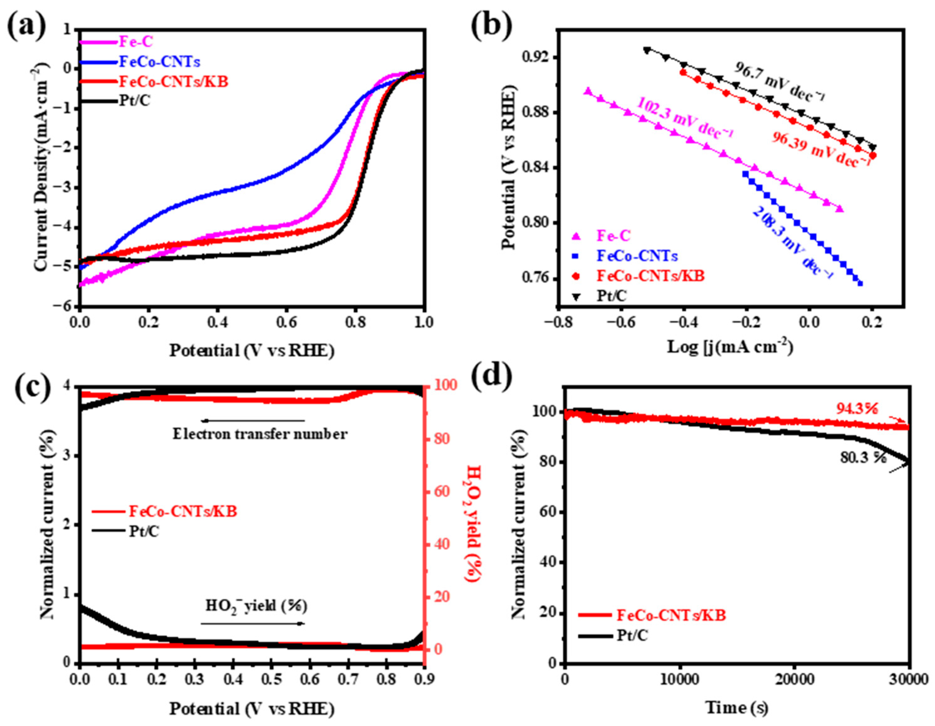
2.2. Electrocatalytic Properties

The ORR and OER performances of the samples were tested in an O2-saturated 0.1 M KOH solution. Figure S7 (Supplementary Materials) depicts the ORR and OER performances of the FeCo-CNTs/KB catalyst carbonized at various temperatures. It is obvious that the bifunctional performance of the FeCo-CNTs/KB is better than that of the FeCo-CNTs/KB-6 and FeCo-CNTs/KB-8 samples. As shown in Figure 3a, the FeCo-CNTs/KB catalyst shows a half-wave potential (0.84 V) comparable to that of Pt/C (0.84 V), which is better than that of the Fe-C (0.63 V) and FeCo-CNTs (0.73 V). Meanwhile, the limiting current density (jL) of the FeCo-CNTs/KB catalyst is 4.84 mA cm−2, which is similar to that of Pt/C (4.86 mA cm−2) and FeCo-CNTs (4.95 mA cm−2). In comparison to Fe-C, the lower activity of the FeCo-CNTs might stem from a lower N and metal content linked to limited active sites, as discussed in XPS, along with sluggish electron transfer due to large, non-uniform carbon nanotubes. Introducing KB yields more uniform, compact carbon nanotubes, enhancing charge transfer and electrical conductivity. As previously discussed, the substantial rise in M-N content attributed to the KB addition, coupled with the synergistic effect of M-N-C and CoFe bimetallic electron interactions, markedly elevates the ORR activity in the FeCo-CNTs/KB catalyst [18]. Compared to the single Fe-N-C active sites, the CoFe-N-C active sites exhibit a narrower energy gap between the highest occupied molecular orbital (HOMO) and the lowest unoccupied molecular orbital (LUMO), which is advantageous for ORRs. Furthermore, around the Fermi energy level, CoFe bimetallic sites demonstrate a higher density of states (DOS), indicating enhanced electron mobility and increased activity [57]. In addition, the Tafel slope value of the FeCo-CNTs/KB catalyst (Figure 3b) is the lowest (96.39 mV dec−1) among the catalyst materials and lower than that of Pt/C (96.7 mV dec−1), proving its excellent ORR dynamic performance. This excellent dynamic property could be due to the formation of a large number of carbon nanotubes with smaller diameters, and the carbon loss during pyrolysis could be supplemented by the introduction of KB as a supplementary carbon source. Figure 3c illustrates that the yield of H2O2 for the FeCo-CNTs/KB catalyst remains below 10%, and the electron transfer number closely approximates four throughout the ORR reaction, similar to that observed with Pt/C. This suggests that FeCo-CNTs/KB catalyst undergoes an efficient 4e transfer process. This observation further supports the role of pyridine–N in facilitating 4e transfer. The FeCo-CNTs/KB catalyst maintains 94.3% of its initial current density after 30,000 s of a continuous reaction, in contrast to Pt/C, with a current density drop of 19.7% (Figure 3d), demonstrating the FeCo-CNTs/KB catalyst’s superior stability over commercial Pt/C. The excellent stability of the FeCo-CNTs/KB catalyst could be due to the maintenance of their hierarchical structure over a long period of electrocatalytic reaction.
The performance of the OER is essential for the charging process of ZABs. Figure 4a shows the LSV curves for Fe-C, FeCo-CNTs, FeCo-CNTs/KB, and RuO2. The FeCo-CNTs/KB catalyst requires 1.68 V to reach 10 mA cm−2, which is much lower than that needed for Fe-C (1.78 V) and FeCo-CNTs (1.71 V) and even better than for RuO2 (1.69 V). The current density enhances rapidly with the overpotential for the FeCo-CNTs/KB catalyst, reflecting its excellent OER kinetics, suggesting that the introduction of FeCo and the formation of uniform carbon nanotubes are beneficial for the OER process. The superior OER performance of the FeCo-CNTs/KB catalyst arises from the increased active site exposure of the M-N-C and FeCo alloy nanoparticles. Tafel curves are fitted to further investigate the kinetics of the OER. As observed in Figure 4b, the FeCo-CNTs/KB catalyst exhibits the minimal Tafel slope of 116.6 mV dec−1, demonstrating its most favorable intrinsic OER kinetics compared to Fe-C (132.9 mV dec−1), FeCo-CNTs (127.6 mV dec−1), and RuO2 (161.3 mV dec−1), further demonstrating its superior OER reaction dynamics. The electrochemical active surface area (ECSA) was assessed by CV curves at various scan rates in the non-Faraday potential range, as shown in Figure S8 (Supplementary Materials). The results demonstrate that the FeCo-CNTs/KB catalyst has a larger ECSA, which is related to the high level of exposure of the active sites of M-N-C associated with its hierarchical structure. Nyquist plots of the samples obtained through EIS (electrochemical impedance spectroscopy) are displayed in Figure 4c, and the FeCo-CNTs/KB catalyst shows a smaller semicircular diameter compared to the Fe-C and FeCo-CNTs, implying the lowest transfer resistance and excellent conductivity, which confirms the positive effects of the formation of carbon nanotubes and the introduction of KB [58]. Electrons face difficulties transferring between Fe-C and iron MOFs because Fe-C is formed solely through the direct calcination of an iron MOF without the creation of carbon tubes. In contrast, FeCo-CNTs produced without the assistance of KB during high-temperature calcination exhibit higher resistance due to the rough and uneven distribution of carbon tubes, affecting the electron transport pathway. However, the addition of KB followed by calcination results in an FeCo-CNTs/KB catalyst with abundant and uniformly sized carbon tubes, establishing an effective pathway for electron conduction. To test the OER stability of the FeCo-CNTs/KB catalyst, current–retention time (i–t) tests were carried out at a potential of 1.60 V (Figure 4d). After 30,000 s of continuous operation, the FeCo-CNTs/KB catalyst had outstanding OER durability and could maintain 94.7% of its initial current density; meanwhile, RuO2 could only maintain 68.3%.

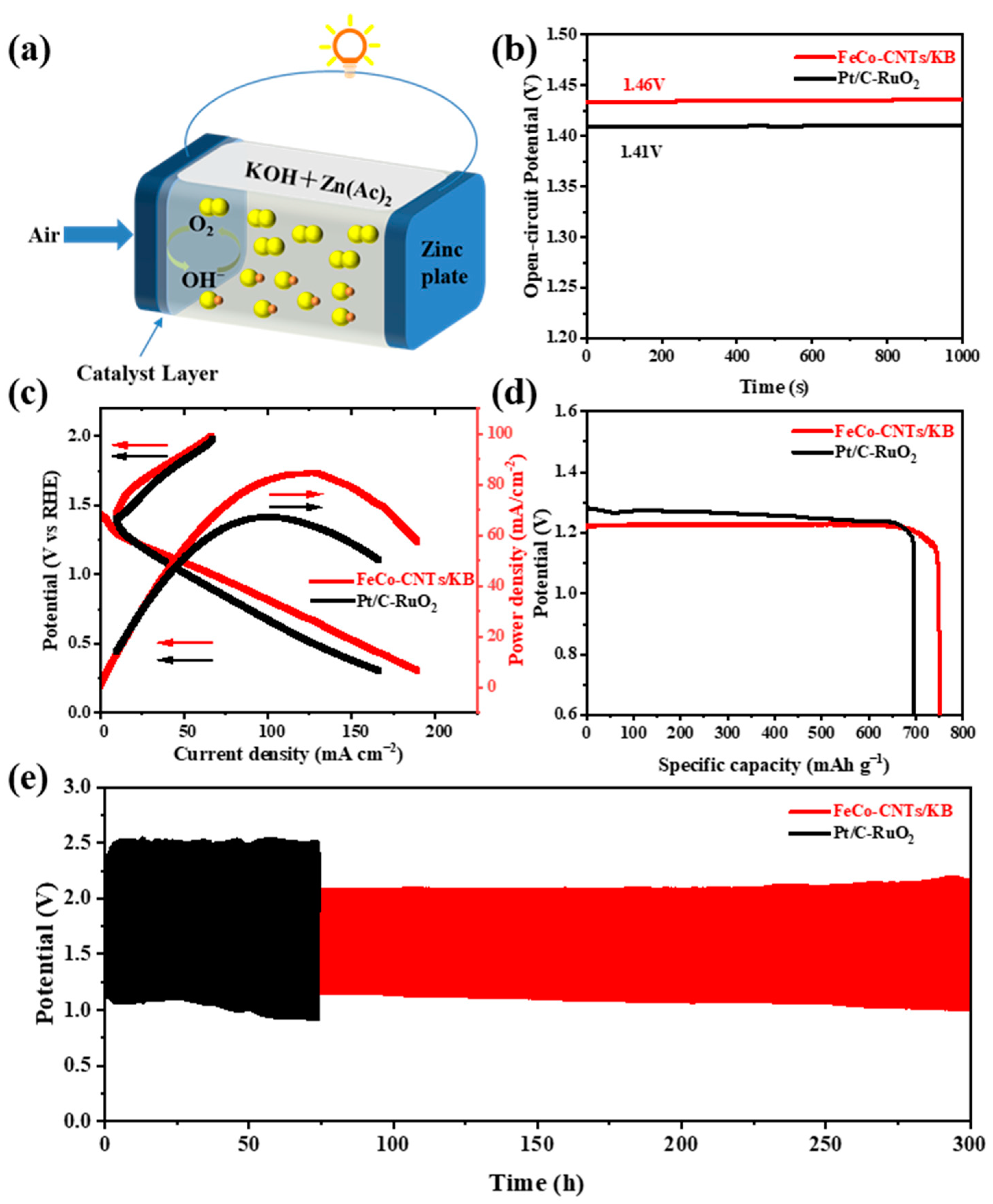
2.3. Aqueous Zn–Air Battery Performance

A zn–air battery was assembled with FeCo-CNTs/KB as the cathode catalyst to further study its actual performance for applications. The ZAB was assembled with a Zn plate, catalysts loaded on carbon paper, and 6 M KOH + 0.2 M Zn(OAc)2 as a cathode, anode, and electrolyte, respectively (Figure 5a). As shown in Figure 5b, The FeCo-CNTs/KB-based ZAB exhibits a stable open-circuit voltage of 1.46 V, which is higher than that of the Pt/C-RuO2-based ZAB (1.41 V). In the charge–discharge and power density plots (Figure 5c), the FeCo-CNTs catalyst exhibits a smaller charge–discharge gap than the Pt/C-RuO2 catalyst, suggesting higher charge and discharge currents under the same voltage. Meanwhile, the peak power density calculated from the related discharge polarization curves is 84.51 mW cm−2 for the FeCo-CNTs/KB-based ZAB, which is superior to that of the Pt/C-RuO2-based ZAB (67.05 mW cm−2). By calculating the mass of the consumed Zn flakes, the specific capacity of the FeCo-CNTs/KB catalyst is 785.3 mAh g−1 higher than a commercial Pt/C-RuO2 catalyst (695.4 mAh g−1). In addition, a FeCo-CNTs/KB-based ZAB with a constant current density of 5 mA cm−2 can be continually charged and discharged after 300 h with a minimal charge–discharge voltage gap, indicating its excellent long-cycle durability (Figure 5e), which is better than that of the Pt/C-RuO2-based ZAB. Figure S9 (Supplementary Materials) depicts SEM images of the cathode catalyst before and after the cycling test. Notably, no significant changes are observed after 300 h, underscoring its exceptional cycle stability. The high performance of the FeCo-CNTs/KB-based ZAB could be due to the excellent ORR and OER properties of the FeCo-CNTs/KB catalyst caused by the synergistic interaction of Fe, Co, and carbon nanotubes, and its unique hierarchical structure improves the effective utilization of active sites, which enhances its long-term durability. Therefore, the FeCo-CNTs/KB catalyst demonstrates significant application potential for energy storage devices as a high-performance bifunctional electrocatalyst.

3. Experimental

3.1. Materials

Glucosamine hydrochloride (AR, 99%) and RuO2 (99.9%) were purchased from Aladdin Industrial Corporation (Shanghai, China). FeCl3·6H2O (AR, 99%), methanol, and N,N-dimethylformamide (DMF) were obtained from Sinopharm Chemical Reagent Corporation (Shanghai, China). Commercial Pt/C (20 wt.%), melamine, and CoCl3·6H2O (AR, 99%) were bought from Alfa Aesar (Shanghai, China). Ketjen black (KB), 2-aminoterephthalic acid (H2ATA), and Nafion117 solution (5 wt.%) were obtained from Lion King Corporation (Tokyo, Japan), Shanghai Macklin Biochemical Corporation (Shanghai, China), and Sigma-Aldrich (Shanghai, China), respectively.

3.2. Preparation of NH2-MIL-101(Fe)

Typically, NH2-MIL-101(Fe) was synthesized according to a previous report [59]. In detail, 2.5 mmol of FeCl3·6H2O and 1.25 mmol of 2-aminoterephthalic acid were dissolved in 15 mL of N, N-dimethylformamide (DMF) and stirred at room temperature for 1 h to form a homogeneous solution. Then, the reactants were sealed in a stainless Teflon-lined autoclave at 110 °C for 24 h. Finally, the products were collected and washed three times with DMF and methanol, respectively, and dried at 60 °C in a vacuum oven.

3.3. Preparation of NH2-MIL-101(Fe)@glu-Co/KB

First, 100 mg of NH2-MIL-101(Fe) was dispersed in 20 mL of deionized water and ultrasonicated for 10 min. Then, 200 mg of glucosamine hydrochloride and 60 mg of CoCl3·6H2O were added to the solution and stirred for 2 h prior to freeze-drying. Finally, the NH2-MIL-101(Fe)@glu-Co above and KB were milled together in a 10:3 mass ratio and named NH2-MIL-101(Fe)@glu-Co/KB.

3.4. Synthesis of FeCo-CNTs/KB

Typically, 50 mg of NH2-MIL-101(Fe)@glu-Co/KB and 2 g of melamine were, respectively, placed in the furnace along the downstream and upstream of the N2 flow and were subjected to a two-step pyrolysis comprising a heat treatment at 200 °C for 2 h at a ramping rate of 5 °C min−1, followed by carbonization at 700 °C for 2 h under flowing N2 gas. Finally, FeCo-CNTs/KB samples were obtained after cooling to room temperature. As a comparison, FeCo-CNTs/KB-6 and FeCo-CNTs/KB-8 were obtained with a similar process to FeCo-CNTs/KB by carbonizing at 600 °C and 800 °C, respectively.
Additionally, FeCo-CNTs and Fe-C were prepared using the same two-step pyrolysis method with FeCo-CNTs/KB using NH2-MIL-101(Fe)@glu-Co and NH2-MIL-101(Fe) as precursors, respectively.

3.5. Electrochemical Measurements

ORR and OER performances were characterized via a standard three-electrode system by using an electrochemical station (CHI 760D) at room temperature. As the working, counter, and reference electrodes, a rotating disk (3.0 mm in diameter) or glassy carbon rotating disk (5.0 mm in diameter), a graphite rod, and Ag/AgCl electrodes were utilized, respectively. A catalyst ink was prepared by combining 4 mg of sample powder, 1 mg of carbon black (XC-72), 800 μL of deionized water, 200 μL of isopropanol, and 20 μL of Nafion117 (5% solution, Sigma, Shanghai, China). The mixture was sonicated for 0.5 h. Subsequently, 3 μL of the catalyst ink was drop-cast onto the surface of a glassy carbon electrode and allowed to dry at room temperature, forming a uniform catalyst layer. ORR and OER polarization curves were obtained using rotating disk experiments (RDE-3A, ALS Co., Salt Lake City, UT, USA) from 0.2 V to 2 V (vs. Ag/AgCl) at 1600 rpm in an O2-saturated KOH (0.1 M) solution with a scan rate of 5 mV s−1. Electrochemical impedance spectroscopy (EIS) was conducted at 1.59 V (vs. RHE) over a frequency range of 100 kHz to 0.01 Hz, with a potential amplitude of 5 mV. Throughout this study, all potentials are reported with reference to the reversible hydrogen electrode (RHE).
The following methods were employed to fabricate zinc–air batteries in a two-electrode configuration. A polished Zn foil with a thickness of 0.08 mm served as the anode, while the electrolyte consisted of a solution containing 6 M of KOH and 0.2 M of Zn(Ac)2. To create the air electrode, a mixture of catalyst, aqueous polytetrafluoroethylene (PTFE), carbon black, and active carbon was combined (weight ratio = 10:35:25:30) and applied onto the surface of a carbon fiber cloth (W1S1009, Cetech, Taizhong, China). The mass loading of the active material was approximately 3 mg cm−2. Power density and charge–discharge polarization plots were recorded using an electrochemical workstation (CHI 760E). Battery cycling tests, including specific capacity and cycling tests, were conducted at room temperature with a current density of 5 mA cm−2 using battery cycling equipment (Neware CT-4008).

4. Conclusions

In summary, an FeCo-CNTs/KB catalyst was synthesized through the pyrolysis of glu-Co-coated NH2-MIL-101(Fe) incorporated with KB, forming a hierarchical structure of carbon nanotubes and FeCo nanoparticles within the carbon matrix or nanotubes. The glu-Co coating facilitated carbon nanotube growth on the matrix, while the KB addition dispersed metal nanoparticles and enabled smaller, uniform nanotube formation, enhancing the FeCo-CNTs/KB catalyst’s ECSA. This unique structure contributed to excellent ORR and OER performance, with an E1/2 of 0.84 V and an overpotential of 0.45 V. It also exhibited long-term stability compared to commercial Pt/C and RuO2. The ZABs incorporating FeCo-CNTs/KB as a cathode catalyst showed improved power density and superior charge–discharge stability (≥300 h) versus Pt/C-RuO2-based ZABs.

Supplementary Materials

The following supporting information can be downloaded at https://www.mdpi.com/article/10.3390/catal14030205/s1: Figure S1: Particle size distribution plots showing the average size (based on measurements of over 50 particles) of (a) NH2-MIL-101(Fe) and (b) NH2-MIL-101(Fe)@glu-Co; Figure S2: SEM image of Fe-C; Figure S3: SEM image of KB; Figure S4: SEM image of NH2-MIL-101(Fe)@glu-Co/KB; Figure S5: EDS elemental mapping images of Fe, Co, N, and C in FeCo-CNTs; Figure S6: N 1s spectra of (a) Fe-C and (b) FeCo-CNTs; Figure S7: (a) ORR and (b) OER LSV curves of FeCo-CNTs/KB at different temperatures; Figure S8: CVs measured at scan rates from 20 to 200 mV s−1 for (a) Fe-C, (b) FeCo-CNTs, and (c) FeCo-CNTs/KB in 1M of KOH. (d) Current density (at 0.965 V) as a function of scan rate derived from (a) to (c); Figure S9: SEM images of cathode catalyst (a) before and (b) after cycling test; Table S1: Elemental compositions of FeCo-CNTs/KB from EDS analysis; Table S2: Elemental compositions (atomic%) in Fe-C, FeCo-CNTs, and FeCo-CNTs/KB; Table S3: N-type contents in Fe-C, FeCo-CNTs, and FeCo-CNTs/KB.

Author Contributions

P.S.: conceptualization, investigation, writing—original draft. X.Y.: software. D.C.: investigation, conceptualization. X.C.: investigation. F.Y.: visualization. B.P.: investigation, conceptualization. H.D.: investigation. J.Y.: conceptualization, methodology, writing—review and editing. L.Y.: project administration, funding acquisition. L.D.: project administration, funding acquisition, supervision, writing—review and editing, resources. All authors have read and agreed to the published version of the manuscript.

Funding

The authors would like to acknowledge support from the National Natural Science Foundation of China (51472174, 61604086, and 21776147), the Shandong Natural Science Foundation (ZR2018BB066, ZR2021YQ32, and ZR2022QB164), and the Taishan Scholars Project of Shandong Province (tsqn201909117).

Data Availability Statement

The authors can confirm that all relevant data are included in the article.

Conflicts of Interest

The authors do not have any financial or non-financial interests that are directly or indirectly related to the work submitted for publication.

References

  1. Li, Y.; Gong, M.; Liang, Y.; Feng, J.; Kim, J.-E.; Wang, H.; Hong, G.; Zhang, B.; Dai, H. Advanced Zinc-Air Batteries Based on High-Performance Hybrid Electrocatalysts. Nat. Commun. 2013, 4, 1805. [Google Scholar] [CrossRef] [PubMed]
  2. Li, Y.; Dai, H. Recent Advances in Zinc–Air Batteries. Chem. Soc. Rev. 2014, 43, 5257–5275. [Google Scholar] [CrossRef] [PubMed]
  3. Guo, Y.; Chen, Y.-N.; Cui, H.; Zhou, Z. Bifunctional Electrocatalysts for Rechargeable Zn-Air Batteries. Chin. J. Catal. 2019, 40, 1298–1310. [Google Scholar] [CrossRef]
  4. Shao, M.; Chang, Q.; Dodelet, J.-P.; Chenitz, R. Recent Advances in Electrocatalysts for Oxygen Reduction Reaction. Chem. Rev. 2016, 116, 3594–3657. [Google Scholar] [CrossRef] [PubMed]
  5. Reier, T.; Nong, H.N.; Teschner, D.; Schlögl, R.; Strasser, P. Electrocatalytic Oxygen Evolution Reaction in Acidic Environments—Reaction Mechanisms and Catalysts. Adv. Energy Mater. 2017, 7, 1601275. [Google Scholar] [CrossRef]
  6. Chen, Y.; Yoo, S.; Zhang, W.; Kim, J.H.; Zhou, Y.; Pei, K.; Kane, N.; Zhao, B.; Murphy, R.; Choi, Y.; et al. Effective Promotion of Oxygen Reduction Reaction by in Situ Formation of Nanostructured Catalyst. ACS Catal. 2019, 9, 7137–7142. [Google Scholar] [CrossRef]
  7. Materials Design and Discovery Group; Chae, H.K.; Siberio-Pérez, D.Y.; Kim, J.; Go, Y.; Eddaoudi, M.; Matzger, A.J.; O’Keeffe, M.; Yaghi, O.M. A Route to High Surface Area, Porosity and Inclusion of Large Molecules in Crystals. Nature 2004, 427, 523–527. [Google Scholar] [CrossRef]
  8. Gao, X.; Xu, T.; Jiang, Z.; Yu, H.; Wang, Y.; He, Y. Rational Construction and Remarkable Gas Adsorption Properties of a HKUST-1-like Tbo-Type MOF Based on a Tetraisophthalate Linker. Dalton Trans. 2019, 48, 16793–16799. [Google Scholar] [CrossRef] [PubMed]
  9. Yang, L.; Zeng, X.; Wang, W.; Cao, D. Recent Progress in MOF-Derived, Heteroatom-Doped Porous Carbons as Highly Efficient Electrocatalysts for Oxygen Reduction Reaction in Fuel Cells. Adv. Funct. Mater. 2018, 28, 1704537. [Google Scholar] [CrossRef]
  10. Sun, M.; Liu, H.; Qu, J.; Li, J. Earth-Rich Transition Metal Phosphide for Energy Conversion and Storage. Adv. Energy Mater. 2016, 6, 1600087. [Google Scholar] [CrossRef]
  11. Wu, G.; Santandreu, A.; Kellogg, W.; Gupta, S.; Ogoke, O.; Zhang, H.; Wang, H.-L.; Dai, L. Carbon Nanocomposite Catalysts for Oxygen Reduction and Evolution Reactions: From Nitrogen Doping to Transition-Metal Addition. Nano Energy 2016, 29, 83–110. [Google Scholar] [CrossRef]
  12. Muthurasu, A.; Sampath, P.; Ko, T.H.; Lohani, P.C.; Pathak, I.; Acharya, D.; Chhetri, K.; Kim, D.H.; Kim, H.Y. Partial Selenium Surface Modulation of Metal Organic Framework Assisted Cobalt Sulfide Hollow Spheres for High Performance Bifunctional Oxygen Electrocatalysis and Rechargeable Zinc-Air Batteries. Appl. Catal. B Environ. 2023, 330, 122523. [Google Scholar] [CrossRef]
  13. Muthurasu, A.; Chae, S.-H.; Hoon Ko, T.; Chandra Lohani, P.; Yong Kim, H. Highly Ordered Nanoarrays Catalysts Embedded in Carbon Nanotubes as Highly Efficient and Robust Air Electrode for Flexible Solid-State Rechargeable Zinc-Air Batteries. J. Colloid Interface Sci. 2022, 616, 679–690. [Google Scholar] [CrossRef] [PubMed]
  14. Muthurasu, A.; Dahal, B.; Mukhiya, T.; Chhetri, K.; Kim, H.Y. Fabrication of Nonmetal-Modulated Dual Metal–Organic Platform for Overall Water Splitting and Rechargeable Zinc–Air Batteries. ACS Appl. Mater. Interfaces 2020, 12, 41704–41717. [Google Scholar] [CrossRef]
  15. Muthurasu, A.; Tiwari, A.P.; Chhetri, K.; Dahal, B.; Kim, H.Y. Construction of Iron Doped Cobalt- Vanadate- Cobalt Oxide with Metal-Organic Framework Oriented Nanoflakes for Portable Rechargeable Zinc-Air Batteries Powered Total Water Splitting. Nano Energy 2021, 88, 106238. [Google Scholar] [CrossRef]
  16. Du, Z.; Yu, P.; Wang, L.; Tian, C.; Liu, X.; Zhang, G.; Fu, H. Cubic Imidazolate Frameworks-Derived CoFe Alloy Nanoparticles-Embedded N-Doped Graphitic Carbon for Discharging Reaction of Zn-Air Battery. Sci. China Mater. 2020, 63, 327–338. [Google Scholar] [CrossRef]
  17. Li, J.-S.; Li, S.-L.; Tang, Y.-J.; Han, M.; Dai, Z.-H.; Bao, J.-C.; Lan, Y.-Q. Nitrogen-Doped Fe/Fe3C@graphitic Layer/Carbon Nanotube Hybrids Derived from MOFs: Efficient Bifunctional Electrocatalysts for ORR and OER. Chem. Commun. 2015, 51, 2710–2713. [Google Scholar] [CrossRef]
  18. Wang, S.; Wang, J.; Wang, X.; Li, L.; Qin, J.; Cao, M. Carbon Hybrid with 3D Nano-Forest Architecture in-Situ Catalytically Constructed by CoFe Alloy as Advanced Multifunctional Electrocatalysts for Zn-Air Batteries-Driven Water Splitting. J. Energy Chem. 2021, 53, 422–432. [Google Scholar] [CrossRef]
  19. Zheng, X.; Cao, X.; Zeng, K.; Yan, J.; Sun, Z.; Rümmeli, M.H.; Yang, R. A Self-Jet Vapor-Phase Growth of 3D FeNi@NCNT Clusters as Efficient Oxygen Electrocatalysts for Zinc-Air Batteries. Small 2021, 17, 2006183. [Google Scholar] [CrossRef] [PubMed]
  20. Jang, J.-H.; Jeffery, A.A.; Min, J.; Jung, N.; Yoo, S.J. Emerging Carbon Shell-Encapsulated Metal Nanocatalysts for Fuel Cells and Water Electrolysis. Nanoscale 2021, 13, 15116–15141. [Google Scholar] [CrossRef]
  21. Cai, P.; Hong, Y.; Ci, S.; Wen, Z. In Situ Integration of CoFe Alloy Nanoparticles with Nitrogen-Doped Carbon Nanotubes as Advanced Bifunctional Cathode Catalysts for Zn–Air Batteries. Nanoscale 2016, 8, 20048–20055. [Google Scholar] [CrossRef]
  22. Khalid, M.; Bhardwaj, P.A.; Honorato, A.M.B.; Varela, H. Metallic Single-Atoms Confined in Carbon Nanomaterials for the Electrocatalysis of Oxygen Reduction, Oxygen Evolution, and Hydrogen Evolution Reactions. Catal. Sci. Technol. 2020, 10, 6420–6448. [Google Scholar] [CrossRef]
  23. Pei, Y.; Qi, Z.; Li, X.; Maligal-Ganesh, R.V.; Goh, T.W.; Xiao, C.; Wang, T.; Huang, W. Morphology Inherence from Hollow MOFs to Hollow Carbon Polyhedrons in Preparing Carbon-Based Electrocatalysts. J. Mater. Chem. A 2017, 5, 6186–6192. [Google Scholar] [CrossRef]
  24. Zhang, X.; Huang, X.; Hu, W.; Huang, Y. A Metal-Organic Framework-Derived Fe–N–C Electrocatalyst with Highly Dispersed Fe–Nx towards Oxygen Reduction Reaction. Int. J. Hydrog. Energy 2019, 44, 27379–27389. [Google Scholar] [CrossRef]
  25. Niu, H.-J.; Chen, S.-S.; Feng, J.-J.; Zhang, L.; Wang, A.-J. Assembled Hollow Spheres with CoFe Alloyed Nanocrystals Encapsulated in N, P-Doped Carbon Nanovesicles: An Ultra-Stable Bifunctional Oxygen Catalyst for Rechargeable Zn-Air Battery. J. Power Sources 2020, 475, 228594. [Google Scholar] [CrossRef]
  26. Gallardo-Donaire, J.; Hermsen, M.; Wysocki, J.; Ernst, M.; Rominger, F.; Trapp, O.; Hashmi, A.S.K.; Schäfer, A.; Comba, P.; Schaub, T. Direct Asymmetric Ruthenium-Catalyzed Reductive Amination of Alkyl–Aryl Ketones with Ammonia and Hydrogen. J. Am. Chem. Soc. 2018, 140, 355–361. [Google Scholar] [CrossRef] [PubMed]
  27. Zhang, M.; Li, H.; Chen, J.; Ma, F.; Zhen, L.; Wen, Z.; Xu, C. Transition Metal (Co, Ni, Fe, Cu) Single-Atom Catalysts Anchored on 3D Nitrogen-Doped Porous Carbon Nanosheets as Efficient Oxygen Reduction Electrocatalysts for Zn–Air Battery. Small 2022, 18, 2202476. [Google Scholar] [CrossRef] [PubMed]
  28. Yang, W.; Chen, L.; Liu, X.; Jia, J.; Guo, S. A New Method for Developing Defect-Rich Graphene Nanoribbons/Onion-like carbon@Co Nanoparticles Hybrid Materials as an Excellent Catalyst for Oxygen Reactions. Nanoscale 2017, 9, 1738–1744. [Google Scholar] [CrossRef] [PubMed]
  29. Wang, Y.; Chen, W.; Chen, Y.; Wei, B.; Chen, L.; Peng, L.; Xiang, R.; Li, J.; Wang, Z.; Wei, Z. Carbon-Based Catalysts by Structural Manipulation with Iron for Oxygen Reduction Reaction. J. Mater. Chem. A 2018, 6, 8405–8412. [Google Scholar] [CrossRef]
  30. Mahmood, A.; Tabassum, H.; Zhao, R.; Guo, W.; Aftab, W.; Liang, Z.; Sun, Z.; Zou, R. Fe2N/S/N Codecorated Hierarchical Porous Carbon Nanosheets for Trifunctional Electrocatalysis. Small 2018, 14, 1803500. [Google Scholar] [CrossRef] [PubMed]
  31. Wang, T.; Kou, Z.; Mu, S.; Liu, J.; He, D.; Amiinu, I.S.; Meng, W.; Zhou, K.; Luo, Z.; Chaemchuen, S.; et al. 2D Dual-Metal Zeolitic-Imidazolate-Framework-(ZIF)-Derived Bifunctional Air Electrodes with Ultrahigh Electrochemical Properties for Rechargeable Zinc-Air Batteries. Adv. Funct. Mater. 2018, 28, 1705048. [Google Scholar] [CrossRef]
  32. Amiinu, I.S.; Liu, X.; Pu, Z.; Li, W.; Li, Q.; Zhang, J.; Tang, H.; Zhang, H.; Mu, S. From 3D ZIF Nanocrystals to Co-Nx/C Nanorod Array Electrocatalysts for ORR, OER, and Zn-Air Batteries. Adv. Funct. Mater. 2018, 28, 1704638. [Google Scholar] [CrossRef]
  33. Amiinu, I.S.; Pu, Z.; Liu, X.; Owusu, K.A.; Monestel, H.G.R.; Boakye, F.O.; Zhang, H.; Mu, S. Multifunctional Mo–N/C@MoS2 Electrocatalysts for HER, OER, ORR, and Zn–Air Batteries. Adv. Funct. Mater. 2017, 27, 1702300. [Google Scholar] [CrossRef]
  34. Su, C.; Cheng, H.; Li, W.; Liu, Z.; Li, N.; Hou, Z.; Bai, F.; Zhang, H.; Ma, T. Atomic Modulation of FeCo–Nitrogen–Carbon Bifunctional Oxygen Electrodes for Rechargeable and Flexible All-Solid-State Zinc–Air Battery. Adv. Energy Mater. 2017, 7, 1602420. [Google Scholar] [CrossRef]
  35. Jiang, M.; Yang, J.; Ju, J.; Zhang, W.; He, L.; Zhang, J.; Fu, C.; Sun, B. Space-Confined Synthesis of CoNi Nanoalloy in N-Doped Porous Carbon Frameworks as Efficient Oxygen Reduction Catalyst for Neutral and Alkaline Aluminum-Air Batteries. Energy Storage Mater. 2020, 27, 96–108. [Google Scholar] [CrossRef]
  36. Chen, X.; Chen, D.; Li, G.; Sha, P.; Yu, J.; Yu, L.; Dong, L. FeNi Incorporated N Doped Carbon Nanotubes from Glucosamine Hydrochloride as Highly Efficient Bifunctional Catalyst for Long Term Rechargeable Zinc-Air Batteries. Electrochim. Acta 2022, 428, 140938. [Google Scholar] [CrossRef]
  37. Xu, Q.; Jiang, H.; Li, Y.; Liang, D.; Hu, Y.; Li, C. In-Situ Enriching Active Sites on Co-Doped Fe-Co4N@N-C Nanosheet Array as Air Cathode for Flexible Rechargeable Zn-Air Batteries. Appl. Catal. B Environ. 2019, 256, 117893. [Google Scholar] [CrossRef]
  38. Duan, X.; Ren, S.; Pan, N.; Zhang, M.; Zheng, H. MOF-Derived Fe, Co@N–C Bifunctional Oxygen Electrocatalysts for Zn–Air Batteries. J. Mater. Chem. A 2020, 8, 9355–9363. [Google Scholar] [CrossRef]
  39. Lin, S.-Y.; Chen, Y.-P.; Cao, Y.; Zhang, L.; Feng, J.-J.; Wang, A.-J. Aminouracil-Assisted Synthesis of CoFe Decorated Bougainvillea-like N-Doped Carbon Nanoflowers for Boosting Zn–Air Battery and Water Electrolysis. J. Power Sources 2022, 521, 230926. [Google Scholar] [CrossRef]
  40. Sun, R.-M.; Zhang, L.; Feng, J.-J.; Fang, K.-M.; Wang, A.-J. In Situ Produced Co9S8 Nanoclusters/Co/Mn-S, N Multi-Doped 3D Porous Carbon Derived from Eriochrome Black T as an Effective Bifunctional Oxygen Electrocatalyst for Rechargeable Zn-Air Batteries. J. Colloid Interface Sci. 2022, 608, 2100–2110. [Google Scholar] [CrossRef]
  41. Meng, H.-L.; Lin, S.-Y.; Feng, J.-J.; Zhang, L.; Wang, A.-J. Coordination Regulated Pyrolysis Synthesis of Ultrafine FeNi/(FeNi)9S8 Nanoclusters/Nitrogen, Sulfur-Codoped Graphitic Carbon Nanosheets as Efficient Bifunctional Oxygen Electrocatalysts. J. Colloid Interface Sci. 2022, 610, 573–582. [Google Scholar] [CrossRef] [PubMed]
  42. Lee, S.-H.; Park, D.-J.; Yang, W.-G.; Ryu, K.-S. Comparison of Electrochemical Performance for Zinc Anode via Various Electrolytes and Conducting Agents in Zn-Air Secondary Batteries. Ionics 2017, 23, 1801–1809. [Google Scholar] [CrossRef]
  43. Li, J.; Meng, Z.; Brett, D.J.L.; Shearing, P.R.; Skipper, N.T.; Parkin, I.P.; Gadipelli, S. High-Performance Zinc–Air Batteries with Scalable Metal–Organic Frameworks and Platinum Carbon Black Bifunctional Catalysts. ACS Appl. Mater. Interfaces 2020, 12, 42696–42703. [Google Scholar] [CrossRef] [PubMed]
  44. Xu, P.; Zhu, J.; Chen, C.; Xie, J.; Wang, M. Bi2S3/Ketjen Black as a Highly Efficient Bifunctional Catalyst for Long-Cycle Lithium-Oxygen Batteries. ChemElectroChem 2019, 6, 3885–3891. [Google Scholar] [CrossRef]
  45. Xun, S.; Xu, Y.; He, J.; Jiang, D.; Yang, R.; Li, D.; Chen, M. MOF-Derived Cobalt Oxides Nanoparticles Anchored on CoMoO4 as a Highly Active Electrocatalyst for Oxygen Evolution Reaction. J. Alloys Compd. 2019, 806, 1097–1104. [Google Scholar] [CrossRef]
  46. Zhang, S.L.; Guan, B.Y.; Lou, X.W. (David) Co–Fe Alloy/N-Doped Carbon Hollow Spheres Derived from Dual Metal–Organic Frameworks for Enhanced Electrocatalytic Oxygen Reduction. Small 2019, 15, 1805324. [Google Scholar] [CrossRef]
  47. Gao, S.; Fan, B.; Feng, R.; Ye, C.; Wei, X.; Liu, J.; Bu, X. N-Doped-Carbon-Coated Fe3O4 from Metal-Organic Framework as Efficient Electrocatalyst for ORR. Nano Energy 2017, 40, 462–470. [Google Scholar] [CrossRef]
  48. Lu, X.; Yang, P.; Wan, Y.; Zhang, H.; Xu, H.; Xiao, L.; Li, R.; Li, Y.; Zhang, J.; An, M. Active Site Engineering toward Atomically Dispersed M−N−C Catalysts for Oxygen Reduction Reaction. Coord. Chem. Rev. 2023, 495, 215400. [Google Scholar] [CrossRef]
  49. Poudel, M.B.; Vijayapradeep, S.; Sekar, K.; Kim, J.S.; Dong, J.Y. Pyridinic-N exclusively enriched CNT encapsulated NiFe interfacial alloy nanoparticles on knitted carbon fiber cloth for bifunctional oxygen catalysts and biaxially flexible zinc-air batteries. J. Mater. Chem. A 2024. [Google Scholar] [CrossRef]
  50. Wang, J.; Wang, J.; Zhang, M.; Li, S.; Liu, R.; Li, Z. Metal-Organic Frameworks-Derived Hollow-Structured Iron-Cobalt Bimetallic Phosphide Electrocatalysts for Efficient Oxygen Evolution Reaction. J. Alloys Compd. 2020, 821, 153463. [Google Scholar] [CrossRef]
  51. Zuo, X.; Chang, K.; Zhao, J.; Xie, Z.; Tang, H.; Li, B.; Chang, Z. Bubble-Template-Assisted Synthesis of Hollow Fullerene-like MoS2 Nanocages as a Lithium Ion Battery Anode Material. J. Mater. Chem. A 2016, 4, 51–58. [Google Scholar] [CrossRef]
  52. Zhang, X.; Hu, X.; Lv, S.; Li, Y.; Ren, J.; Huang, Y. Hollow NH2-MIL-101@TA Derived Electrocatalyst for Enhanced Oxygen Reduction Reaction and Oxygen Evolution Reaction. Int. J. Hydrog. Energy 2021, 46, 38692–38700. [Google Scholar] [CrossRef]
  53. Sun, Z.; Wang, Y.; Zhang, L.; Wu, H.; Jin, Y.; Li, Y.; Shi, Y.; Zhu, T.; Mao, H.; Liu, J.; et al. Simultaneously Realizing Rapid Electron Transfer and Mass Transport in Jellyfish-Like Mott–Schottky Nanoreactors for Oxygen Reduction Reaction. Adv. Funct. Mater. 2020, 30, 1910482. [Google Scholar] [CrossRef]
  54. Liu, Q.; Liu, X.; Xie, Y.; Sun, F.; Liang, Z.; Wang, L.; Fu, H. N-Doped Carbon Coating Enhances the Bifunctional Oxygen Reaction Activity of CoFe Nanoparticles for a Highly Stable Zn–Air Battery. J. Mater. Chem. A 2020, 8, 21189–21198. [Google Scholar] [CrossRef]
  55. Huang, L.-B.; Zhao, L.; Zhang, Y.; Luo, H.; Zhang, X.; Zhang, J.; Pan, H.; Hu, J.-S. Engineering Carbon-Shells of M@NC Bifunctional Oxygen Electrocatalyst towards Stable Aqueous Rechargeable Zn-Air Batteries. Chem. Eng. J. 2021, 418, 129409. [Google Scholar] [CrossRef]
  56. Zhang, S.; Zhao, S.; Huang, S.; Hu, B.; Wang, M.; Zhang, Z.; He, L.; Du, M. Photocatalytic Degradation of Oxytetracycline under Visible Light by Nanohybrids of CoFe Alloy Nanoparticles and Nitrogen-/Sulfur-Codoped Mesoporous Carbon. Chem. Eng. J. 2021, 420, 130516. [Google Scholar] [CrossRef]
  57. Wang, D.; Xu, H.; Yang, P.; Lu, X.; Ma, J.; Li, R.; Xiao, L.; Zhang, J.; An, M. Fe–N4 and Co–N4 Dual Sites for Boosting Oxygen Electroreduction in Zn–Air Batteries. J. Mater. Chem. A 2021, 9, 13678–13687. [Google Scholar] [CrossRef]
  58. Wang, L.; Yang, H.; Pan, G.; Miao, L.; Chen, S.; Song, Y. Polyaniline-Carbon Nanotubes@Zeolite Imidazolate Framework 67-Carbon Cloth Hierarchical Nanostructures for Supercapacitor Electrode. Electrochim. Acta 2017, 240, 16–23. [Google Scholar] [CrossRef]
  59. Taha, A.A.; Huang, L.; Ramakrishna, S.; Liu, Y. MOF [NH2-MIL-101(Fe)] as a Powerful and Reusable Fenton-like Catalyst. J. Water Process Eng. 2020, 33, 101004. [Google Scholar] [CrossRef]
Scheme 1. Schematic diagram of the preparatory procedure for FeCo-CNTs/KB.
Catalysts 14 00205 sch001
Figure 1. SEM images of (a) NH2-MIL-101(Fe), (b) NH2-MIL-101(Fe)@glu-Co, (c) FeCo-CNTs, and (d) FeCo-CNTs/KB. (e) TEM and (f) HRTEM images of FeCo-CNTs/KB. (gk) EDS elemental mapping images of Fe, Co, N, and C in FeCo-CNTs/KB.
Catalysts 14 00205 g001
Figure 2. (a) XPS survey spectrum and (b) C 1s, (c) N 1s, (d) Co 2p, and (e) Fe 2p spectra of FeCo-CNTs/KB. (f) XRD patterns of Fe-C, FeCo-CNTs, and FeCo-CNTs/KB.
Catalysts 14 00205 g002
Figure 3. (a) ORR Linear Sweep Voltammetry (LSV) curves and (b) Tafel plots of Fe-C, FeCo-CNTs, FeCo-CNTs/KB, and Pt/C at a rotation rate of 1600 rpm with a scan rate of 10 mV s−1 in an O2-saturated 0.1 M KOH solution. (c) Electron transfer number and H2O2 yield curves and (d) current–retention time (i–t) curves at 0.715 V (vs. RHE) for FeCo-CNTs/KB and Pt/C catalysts.
Catalysts 14 00205 g003
Figure 4. (a) OER catalytic performances and (b) Tafel plots of Fe-C, FeCo-CNTs, FeCo-CNTs/KB, and RuO2 in O2-saturated 0.1 M KOH solution with a sweeping rate of 10 mV s−1. (c) Nyquist plots of Fe-C, FeCo-CNTs, and FeCo-CNTs/KB (the inset is the equivalent circuit diagram). (d) Current–retention time (i–t) curves of FeCo-CNTs/KB and RuO2 catalysts at 1.6 V (vs. RHE) for 30,000 s.
Catalysts 14 00205 g004
Figure 5. (a) Schematic diagram of a ZAB. (b) Open-circuit potential curves, (c) charge–discharge and power density plots, (d) specific capacities, and (e) galvanostatic cycling stability of FeCo-CNTs/KB and Pt/C-RuO2-based ZABs at a current density of 5 mA cm−2.
Catalysts 14 00205 g005
Disclaimer/Publisher’s Note: The statements, opinions and data contained in all publications are solely those of the individual author(s) and contributor(s) and not of MDPI and/or the editor(s). MDPI and/or the editor(s) disclaim responsibility for any injury to people or property resulting from any ideas, methods, instructions or products referred to in the content.

