Article

A Highly Efficient Dual Rotating Disks Photocatalytic Fuel Cell with Wedged Surface TiO2 Nanopore Anode and Hemoglobin Film Cathode

1
School of Environmental Science and Engineering, Shanghai Jiao Tong University, No. 800 Dong Chuan Rd., Shanghai 200240, China
2
Department of Sciences, John Jay College and the Graduate Center, The City University of New York, New York, NY 10019, USA
*
Author to whom correspondence should be addressed.
Catalysts 2016, 6(8), 114; https://doi.org/10.3390/catal6080114
Submission received: 15 April 2016 / Revised: 19 July 2016 / Accepted: 19 July 2016 / Published: 4 August 2016
(This article belongs to the Special Issue Photocatalytic Wastewater Treatment)

Abstract

:
In this study, a dual rotating-disk photocatalytic fuel cell using TiO2 on Ti plate with a wedged surface as the anode and hemoglobin (Hb) on graphite as the cathode was investigated and found to show excellent performance of simultaneous organic pollutant degradation and electricity generation. This study is based on a well-developed photocatalytic fuel cell equipped with dual rotating disks for wastewater treatment that we developed previously, and the innovation of this new device is using a hemoglobin on graphite cathode for in situ hydrogen peroxide (H2O2) generation. The result proved with confidence that H2O2 was generated in situ on a cathode surface with the exited electron transferred from organic oxidation in a photoanodic half cell, and the organic pollutants were removed by the reaction with H2O2 and ·OH in a cathodic half cell. This design uses the invalid excited electron from the photoanode and enhances the overall performance of Rhodamine B degradation compared with the cells using the cathode without Hb. Compared with traditional photocatalytic reactors, the photocatalytic fuel cell developed above shows much better utilization efficiency of incident light and a higher degradation performance of organic pollutants and a larger photocurrent.

Graphical Abstract

1. Introduction

TiO2 photocatalytic wastewater treatment is one of the most economical and advanced wastewater treatments with promising environmental applications. Since the first use of a TiO2 photocatalytic anode to treat organic contaminants in water by Fujishima and Hondainin 1976 [1], a long development proceeded, and TiO2 photocatalysis has been practically used in wastewater treatment [2,3], air purification [4], hydrogen production [5], and dye-sensitized solar cell [6], and has become a focus of wastewater and air treatments. Fundamentally, the TiO2 semiconductor is firstly excited under irradiation by UV, through which process electron-hole pairs are formed on the surface of the TiO2, and the excited hole reacts with the compounds. Usually, the energy level of the excited hole is extremely low, being 3.0 eV for a typical TiO2, and they can easily react with the electron from the contacted compounds, generally resulting in the rapid oxidation of these compounds [7]. However, the exited holes can not only get electrons from external sources, but also recombine with the internally excited electrons, which theoretically reduces its photocatalytic activity. In fact, the electrons are critically accumulated after being excited while using TiO2. The way to prevent electron-hole recombination is to transfer the excited electrons as quickly as possible. One option is the addition of a counter electrode, also called a cathode, to form an external circuit through which the excited electron can be promptly transferred to the cathode after its excitation. We have proven this idea by using a dual rotating disk photoelectrochemical cell (PEC) containing a copper cathode. The results showed that this innovation could not only significantly enhance the photo-oxidative performance in the photoanodehalf cell, but also allow the more flexible and favorable reaction of the transferred electron, such as by using it to generate hydrogen peroxide (H2O2) and further ·OH by which the organic compound can also be degraded in the cathodic half cell. The electrocatalytic generation of H2O2 in situ is quite interesting in wastewater remediation. Although its own standard redox potential is 1.763 V vs. Standard Hydrogen Electrode (SHE) in acidic solution and 0.88 V vs. SHE in alkaline solution, ·OH, which is the reaction intermediate product of H2O2, is a strong oxidant and super-reactive, and more importantly, it is easy to obtain ·OH in situ from the reaction of H2O2, e.g., through the Fenton reaction. By reaction with ·OH, the organic compounds in wastewater could be easily oxidized. The limitation of using H2O2 is its transportation and storage [2,7,8]. H2O2 is quite unstable and it is contained in lists of hazardous substances, which mandates quite strict supervision and control of transportation. Therefore, an improved design of the cathode part in the PEC has performance benefits for both the photoanodic and cathodic half cells.
The difficulty in this selective generation of H2O2 on the cathodic half cell is the catalyst. The selectivity to H2O2 of most metal catalysts is not good, and the substrate of the electrode is usually metal. One suggestion is the synthesis of metal-organic composite electrodes for cathodes in PEC, using an organic-modified metal electrode, e.g., hemoglobin (Hb) which is a natural macromolecular protein with intrinsic peroxidase activity due to its close structural similarity to peroxidase [8]. This material is stable and cheap [9]. The most attractive attribute of Hb is that it shows a high reactivity toward oxygen reduction to H2O2 with high selectivity [10]. Therefore, using Hb as the cathodic catalyst for H2O2 generation in a PEC wastewater treatment device should improve the overall performance [11,12,13].
In this study, the application of an Hb-modified cathodic electrode is investigated in a dual rotating disk photocatalytic fuel cell (RPFC). TiO2 nanopores on the surface of the wedged surface Ti rotating disk electrode are fabricated using the electrochemical anodization method according to our and other previous reports focusing the thin-film devices, especially rotating disk reactors [3,14,15,16,17,18,19,20]. The Hb film on graphite rotating-disk electrode is prepared using an enzyme immobilization method [10]. Both of these electrodes are installed in an RPFC [21]. The reason to use a dual rotating-disk device is that it could reduce the solution’s absorption of incident light and thereby improve its utilization efficiency and overall oxidation performance according to our previous study [16,22]. The use of the wedge surface of the Ti electrode is to further enhance its light adsorption via well designed internal reflection between the wedge surfaces. The result shows that a Schottky barrier can enhance the photo electron transfer from the semiconductor to the metal substrate to break the equilibrium distribution of holes and electrons on the surface, leading to a continuous transfer of electrons [23,24] that can be used on the Hb electrode surface [25,26]. H2O2 is generated in situ on the Hb cathode surface through photo electron reduction reactions and then ·OH is generated by the reaction of H2O2 and an electron. Thus, the organic compounds in the cathode chamber are efficiently degraded by the photogenerated ·OH with the catalyst of Hb. The whole process is named “photo enzymatic degradation” accordingly. This dual rotating-disk photocatalytic fuel cell system not only degrades organic pollutants but also provides renewable electricity simultaneously via an external circuit.

2. Results and Discussion

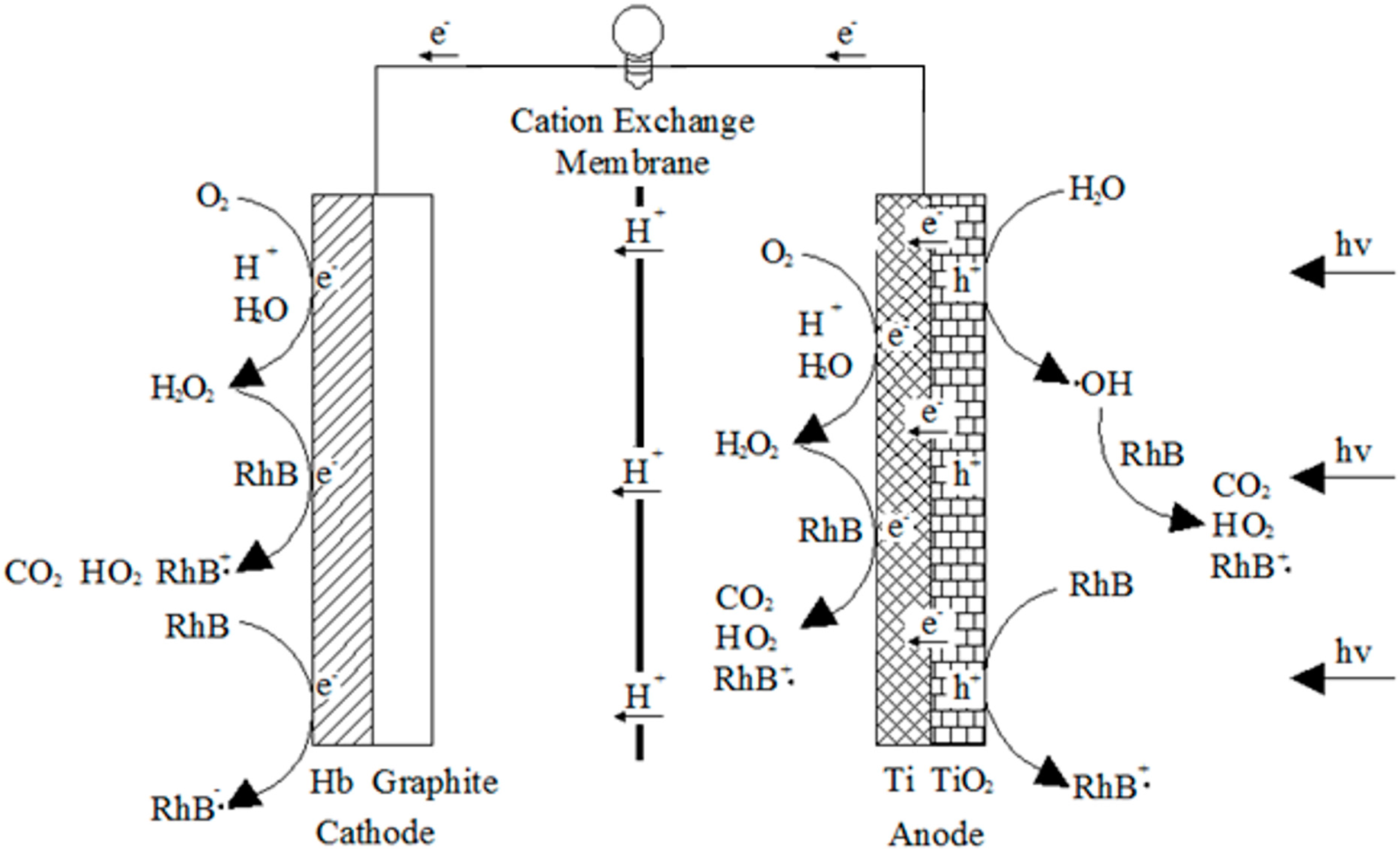
2.1. Electron Transfer and Surface Reaction in a Typical RPFC System

In a typical RPFC system with a TiO2 wedged surface nanopore rotating-disk anode and Hb-graphite rotating-disk cathode, all the reactions are supposed to be spontaneous under UV illumination based on our design. In this way, the device could be efficient and economical for wastewater treatment with a high pollutant oxidation benefit and low operation cost. All the possible surface reactions on the electrodes in the RPFC are schematically shown in Figure 1. The surface reactions start with electron transfer from the organic compound to the excited hole on the TiO2 surface. In the anodic half cell, the excited holes oxidize RhB to CO2 and H2O, with a possible intermediate product of RhB+·. Meanwhile the photoelectrons can be transferred from the TiO2 anode to the Hb-graphite rotating-disk cathode through an external circuit, generating photocurrent with a Schottky barrier [24]. H+ moves to the cathodic half cell through the cation membrane and reacts with O2 to produce H2O2 on the surface of the cathode. Compared to the traditional photocatalytic process, the in situ generation of H2O2 is the key to the design. Due to its close structural similarity to peroxidase, the presence of Hb accelerates the formation of H2O2 greatly improving the generation rate of ·OH. Most of the RhB is degraded to RhB+·,CO2, and H2O by ·OH and H2O2.
Potassium titanium oxalate titration [27] is used to calculate the generation of H2O2. 0.05 mol/L potassium titanium oxalate solution containing 2.0 g/L Na2SO4 is added into both reaction chambers. In the anode half-cell, potassium titanium oxalate is used as the fuel of this RPFC, and in the cathode chamber, it is used to capture H2O2. These reactions result in the reaction medium changing from colorless to yellow. The color change is detected by a UV–Vis photometer, and the concentration of H2O2 is quantified according to a standard line premeasured by given concentrations of H2O2. In fact, not all of the photoelectrons and H+ are transferred to the cathode, as they react in the anode cell and generate H2O2, which causes the color of this solution to also change from colorless to yellow. After 2 h, the solution absorbance in the anode cell is 0.097, while, the absorbance in the cathode cell is 0.160. Hence, the transfer efficiency of the photoelectrons from the anode to the cathode was approximately 62.3%.

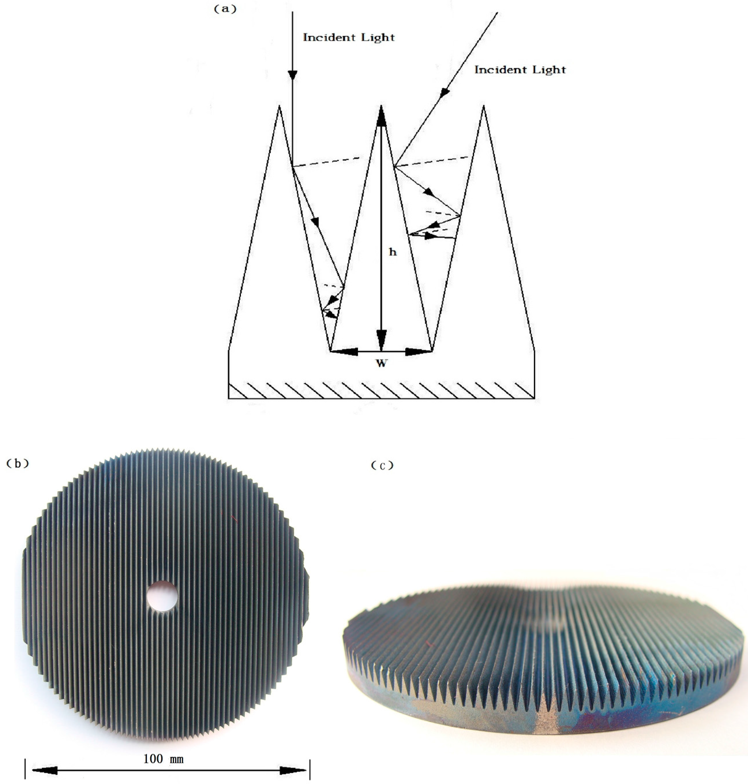
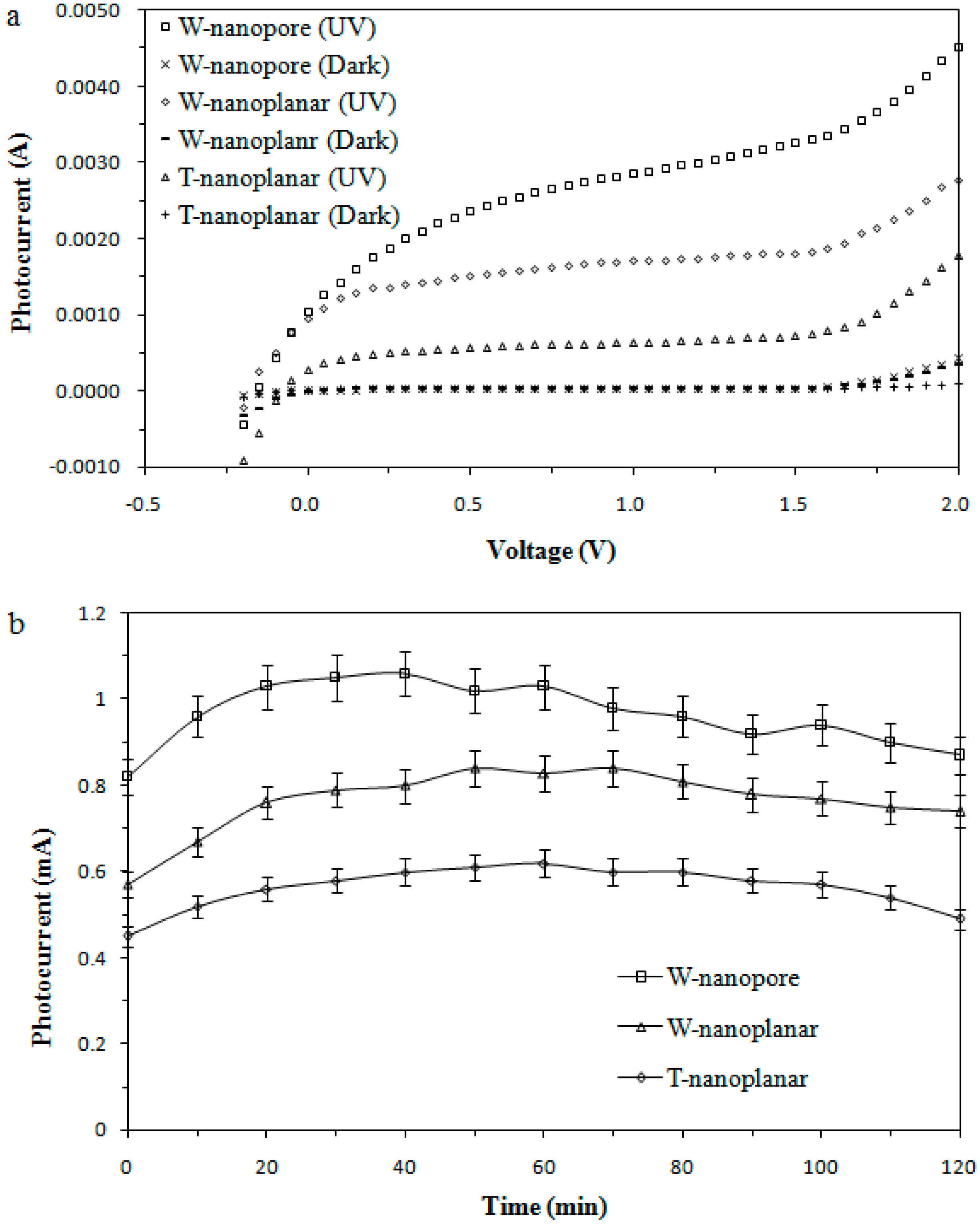
2.2. Enhanced Light Absorbance using Wedged Surface TiO2 Nanopore Electrode

The wedged surface structure in this experiment is designed to enhance the light absorption via internal reflection, also known as light trapping. This idea is inspired by the wide using of a wedged surface material in sound absorption design, in which the sound waves hit a surface without generating any audible sound in an anechoic room. It is reported that the acoustic wedged surface structure can efficiently muffle sound waves of different frequencies [28]. A similar morphology should also be functional in trapping light, although it has rarely been used in this way so far. The wedged surface structure for the capture of light energy in TiO2 photocatalytic degradation is shown in Figure 2a. A typical incident light is reflected multiple times on the surface of the wedged structure, and therefore the light energy is utilized multiple times, improving the energy utilization efficiency of the incident light. Compared with the planar rotating disk electrode with the same dimensions, the wedged surface structure exhibits a larger surface area, and therefore more pollutants can be captured and degraded. The top view and side view of a real wedged surface TiO2 anode are shown in Figure 2b and Figure 2c, respectively.
The original wedged surface Ti rotating-disk electrode is manufactured by electrochemical anodization and is annealed in a muffle furnace causing a continuous TiO2 nanopore structure to emerge. A scanning electron microscope (SEM) image is shown in Figure 3a. This TiO2 nanopore structure has many holes of diameter varying from 200 to 500 nm. The microstructure of the electrode is useful to reduce the reflection of the incident light and diminish the recombination of electron-hole pairs. Figure 3b shows the surface microstructure of the sol-gel TiO2 nanoplanar rotating-disk electrode which is also widely used for the fabrication of TiO2 thin films in a PFC for wastewater. The morphology of the TiO2 film from the sol-gel method is totally different, basically consisting of small irregular fragments. The cracking is supposed to be caused by asymmetry cooling. In general, the anodized TiO2 nanopore microstructure has a much larger surface area than the sol-gel TiO2 nanoplanar microstructure.
The crystal phase of the wedged surface TiO2 nanopore electrode is shown in Figure 3c. The sample has a high degree of crystallization, as shown by the highly intense and sharp peaks. The peak at 25.34° corresponds to (101) of the anatase phase (JCPDS card No. 731764). The anatase phase TiO2 has a higher photocatalytic activity than the rutile phase TiO2 [29]. The peaks at 39.36° and 40.34° show the elemental Ti that is from the substrate of the Ti rotating disk. Figure 4a compares the photocurrent responses of the wedged surface TiO2 nanopore (W-nanopore) anode, wedged surface TiO2 nanoplanar (W-nanoplanar) anode and traditional TiO2 nanoplanar (T-nanoplanar) anode by linear sweep voltammetry in 50 mg/L RhB solution. The photoanodeis under the illumination of UV light (11 W), and the applied potential is set in the range from −0.2 to +2.0 V vs. SCE. The W-nanopore anode has a significantly larger photocurrent response than the W-nanoplanar anode or T-nanoplanar anode. At an applied potential of 1.5 V vs. SCE, the photocurrent of the W-nanopore anode is approximately 6 times higher than that of the T-nanoplanar anode. Even compared to the W-nanoplanar anode, the W-nanopore anode has 1.8 times the photocurrent response. The observed dark current for all samples are found to be negligible. This shows that in the same condition of incident light, the W-nanopore anode possesses excellent performance of enhancing the incident light utilization efficiency and diminishing the recombination of electron-hole pairs. When these three types of anode are separately used in RPFCs, different photocurrents are output due to their different incident light utilization efficiencies. Figure 4b shows the photocurrent results of these anodes in the actual operation process. The W-nanopore anode exhibits better performance of photocurrent output than the W-nanoplanar anode or T-nanoplanar anode.

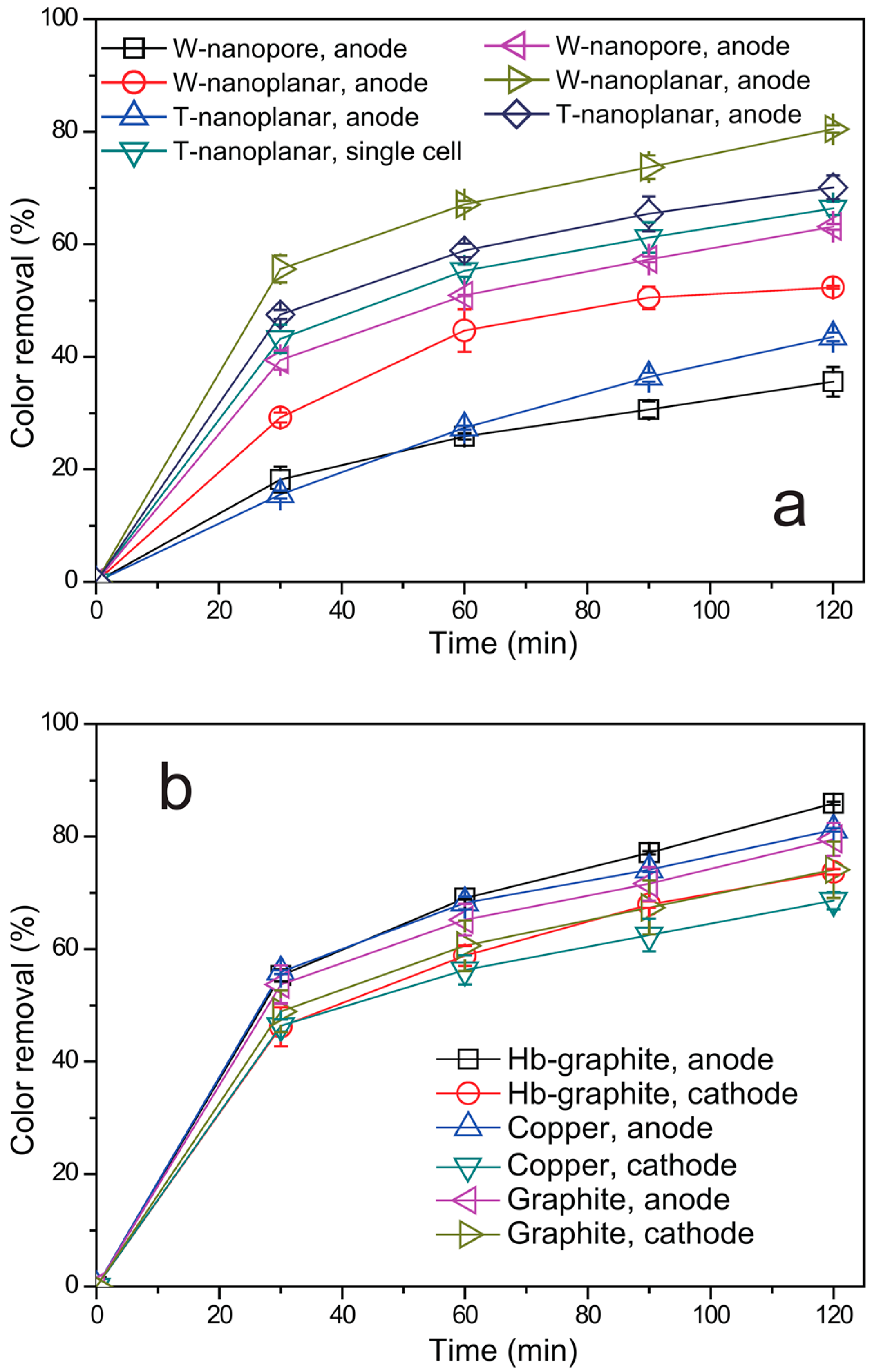
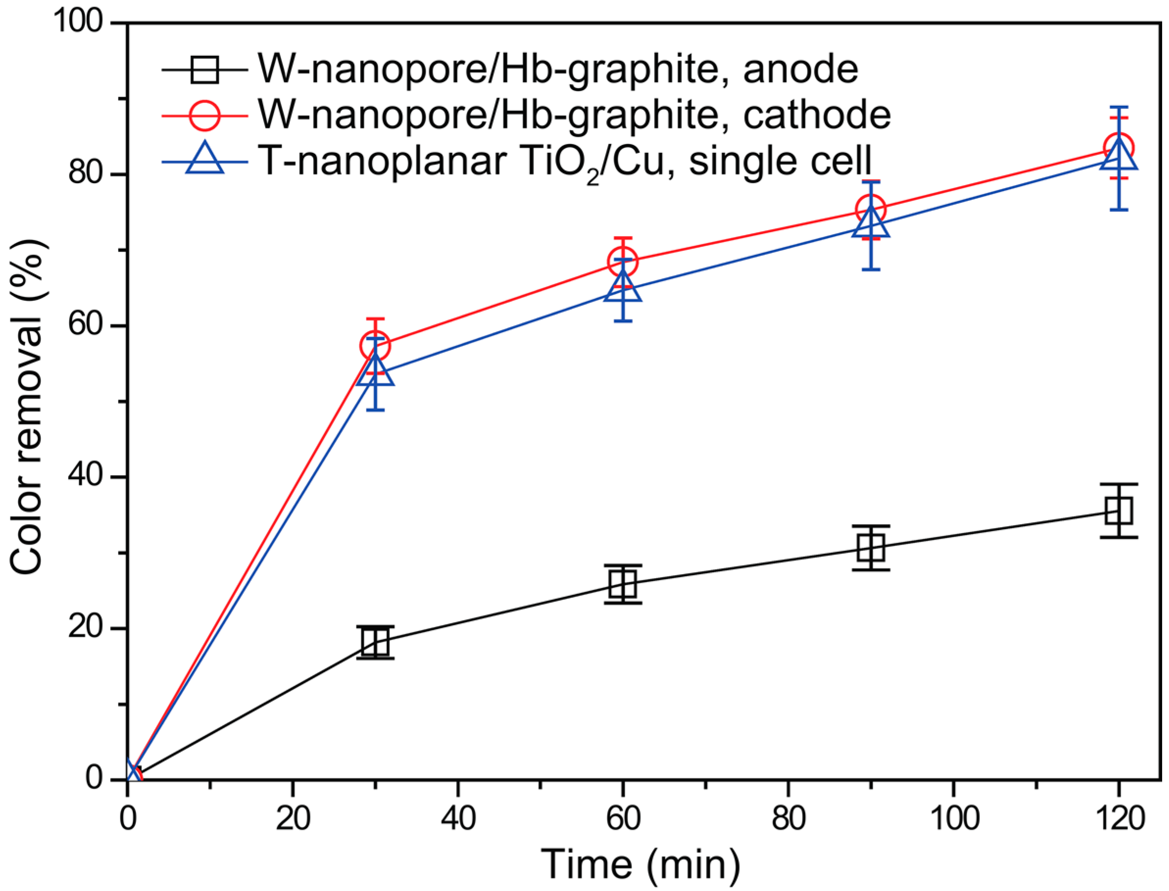
2.3. Degradation Performance of the RPFC System

The degradation performance of the newly designed RPFC is quantitatively investigated by the comparison with traditional systems. The color removal of the RhB simulated wastewater is shown in Figure 5. When using a W-nanoplanar or T-nanoplanar electrode in the RPFC, the color of the RhB can be efficiently removed, as shown in Figure 5a. However, the W-nanopore anode shows much higher degradation efficiencies in the anodic half cell. An interesting observation is that the cathodic half cell shows a higher degradation performance even with the same graphite cathode, indicating an enhanced surface reaction in the cathodic half cell. There are two reasons for this cathodic enhancement. First, it is due to the enhanced electron transfer from the anode when using the W-nanopore. Because the W-nanopore anode has a higher incident light utilization efficiency and stronger electron-hole pair rapid recombination inhibition ability, it should also have a better external electron transfer. Second, it is due to the novel reaction of electrons in the cathodic half cell, which is proved to be the oxygen reduction to hydrogen peroxide. The benefit of the possible cathodic reaction is further investigated by using the Hb-graphite electrode, graphite electrode, and Cu electrode. The W-nanopore electrode is used as the anode during these comparative tests, and the results are shown in Figure 5b. The results show that the Hb-graphite cathode has a much better degradation performance of RhB than either the graphite or Cu cathode, which is supposed to be caused by the reaction of the in situ generated H2O2 on the surface of the Hb-graphite cathode, resulting in an accelerated generation of ·OH. On the surface of the pure graphite electrode, a 4-electron reaction produced H2O, reducing the generation of H2O2 [10]. The generated Cu2+ will react with electrons and retard the degradation efficiency of the target pollutants [30].
Using the W-nanopore TiO2 anode and Hb-graphite cathode, this RPFC achieved 83.5% and 82.1% color removal in the anodic and cathodic half-cells, respectively, as shown in Figure 6. The color removal of RhB is further calculated using a standard curve, 0.38 mg RhB is removed on every cm2 TiO2 photocatalyst in the W-nanopore TiO2 anode and Hb-graphite cathode system. Compared to 0.30 mg·cm−2 for the W-nanoplanar TiO2 anode and graphite cathode system and 0.08 mg·cm−2 for the T-nanoplanar TiO2 anode and Cu single cell system, indicating that the W-nanopore TiO2 anode and Hb-graphite cathode system shows excellent degradation efficiency of the target compound RhB.

3. Material and Methods

3.1. Materials and Reagents

A wedged surface Ti rotating-disk (purity of 99.6%, diameter of 10 cm, thickness of 1 cm, surface area of 78.5 cm2) is used as the TiO2 nanopore electrode substrate. A graphite rotating disk (purity greater than 98%, diameter of 10 cm, thickness of 1 cm) and a Cu rotating disk (purity greater than 98%, diameter of 10 cm, and thickness of 1 mm) are each used as cathodes. Hb from bovine blood and chitosan (CS) are used to modify the graphite cathode. Ammonium fluoride (NH4F) andethylene glycol are employed as the anodization electrolytes for TiO2 nanopore preparation. Rhodamine B (RhB) is used as a typical organic pollutant. Simulated wastewater containing50 mg·L−1 RhB and 2.0 g·L−1 sodium sulfate (Na2SO4) is used as the electrolyte in the photocatalytic degradation experiments. All solutions are prepared using deionized water.

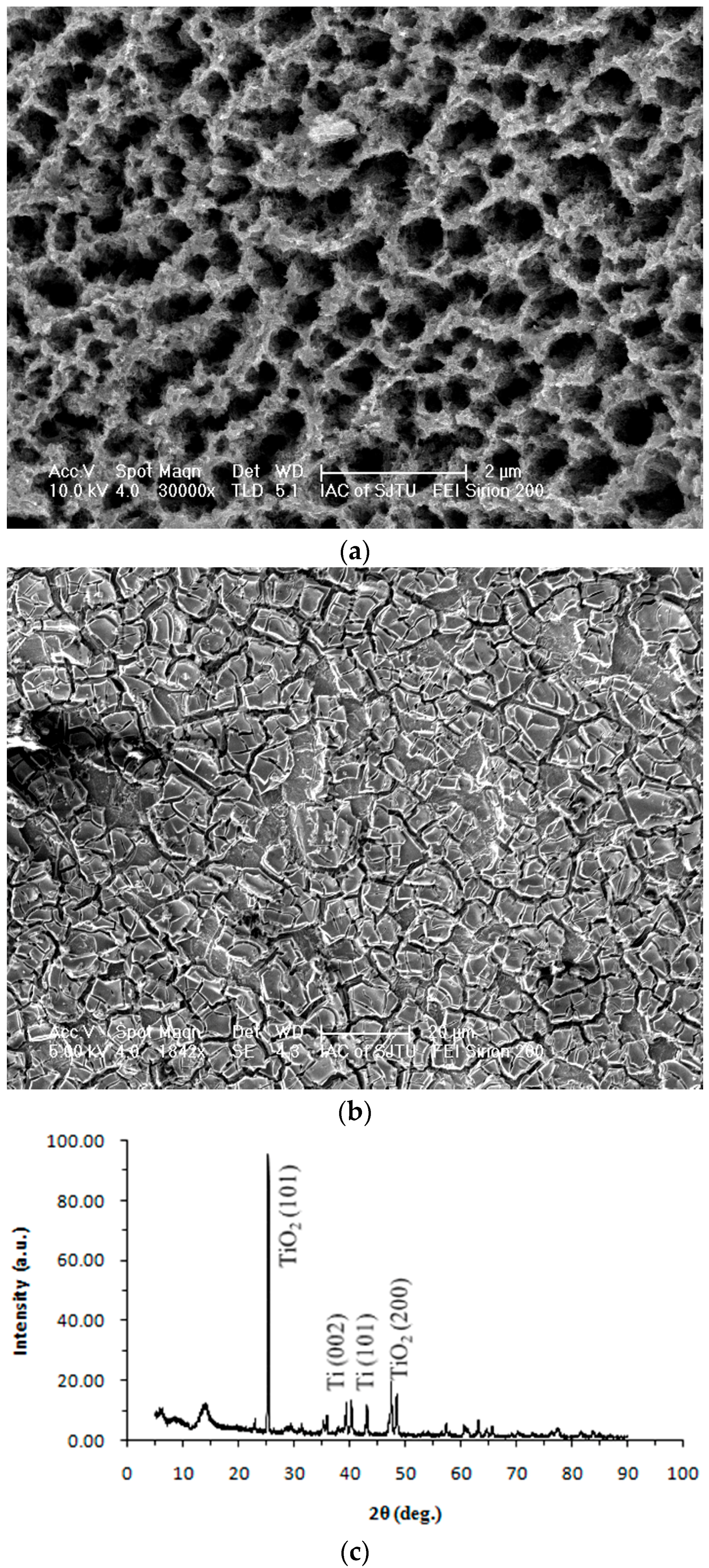
3.2. Fabrication of TiO2/Ti Wedge-Surface Nanopore Rotating-Disk Anode

Generally, the TiO2 wedged surface nanopore rotating-disk anode is prepared using the electrochemical anodization method [14,15,16]. The planar Ti substrate is cut by a 2D wire electrode to form a round disk of 10 cm with a surface of a cm-scaled wedge. The electrodes are polished and subsequently ultrasonically cleaned by deionized water and acetone for 15 min each, and the prepared Ti substrate is further installed in an electrolysis cell for the anodization process. In detail, a 1000 mL beaker is used as the reaction cell. The electrolyte solution contains ethylene glycol with NH4F (0.3 wt %) and H2O (2 wt %). A Cu rotating-disk is used as the counter electrode and is installed in parallel with the Ti electrode. The distance between the two electrodes is 5 cm. The applied voltage is held constant at 40 V by a potent iostat during the whole anodization process, with the Ti and Cu electrodes connected to the positive and negative poles, respectively. The temperature of the cell is maintained at 20 °C with a water bath, and the reaction time is 2 h. The prepared electrode is cleaned by deionized water again and then annealed at 550 °C for 2 h in an air atmosphere with a heating rate of 4 °C/min.

3.3. Immobilization of Hb on the Graphite Electrode

Hb is immobilized on the graphite rotating-disk by a previously reported method [10]. A 0.2 wt % CS solution is obtained by dissolving commercial CS particles in 1 wt % acetic acid solution. A planar graphite rotating disk is dipped into 100 mL CS solution containing 50 mg Hb for 20 min and is then dried in air for another 30 min. The dipping and drying process is repeated 3 times to form a thin film of CS-Hb. The graphite rotating disk is dried in air for 2 h to obtain a solid thin film. A UV–Vis photometer is used to detect the Hb concentrations in the initial and final solutions. Based on the concentration difference, approximately 83% Hb (0.106 mg·cm−2) is immobilized.

3.4. Characterization of the Electrodes

The surface morphology of the wedge-surface TiO2 nanopore electrode is characterized with a field emission scanning electron microscope (FEI, Sirion200, Hillsboro, Oregon, OR, USA). An X-ray diffractometer (Bruker, D8 Advance, Karlsruhe, Germany) is employed to detect the TiO2 crystalline structure of the TiO2 wedged surface rotating disk. The scanning rate is set to 5 °/min and the 2θ range is from 10° to 90°.

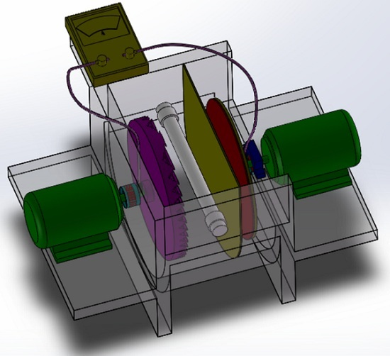
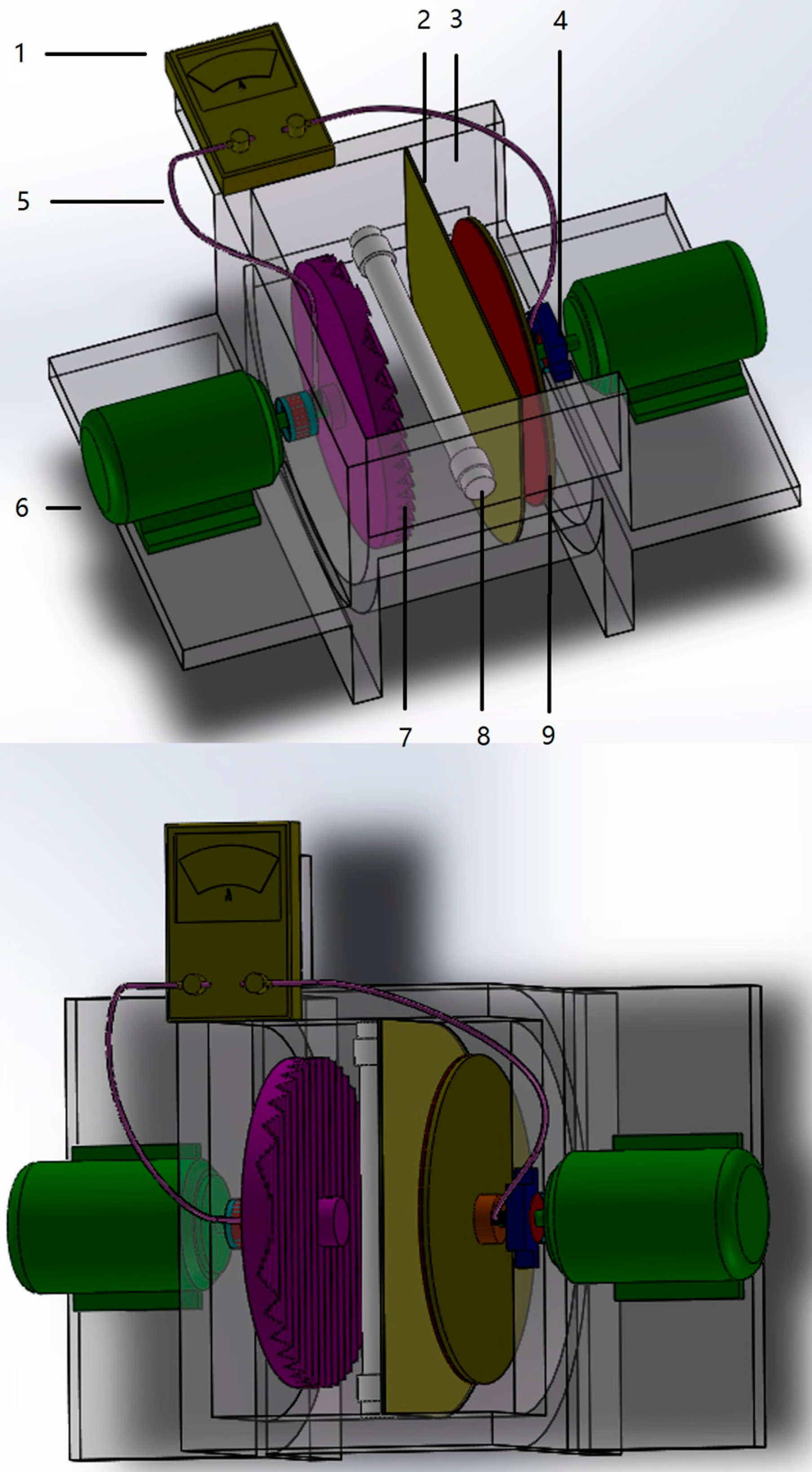
3.5. Dual Rotating-Disk Photocatalytic Fuel Cell

A schematic drawing of the dual rotating-disk fuel cell reactor is shown in Figure 7. Two semi-circular perspex chambers are assembled together to house each of the anode and cathode cells. A cation exchange membrane is placed between the anode and the cathode cells. The volume for each cell is 200 mL. An 11 W mercury lamp (254 nm) is chosen to provide UV illumination. The surface of the anode with a wedge surface is fixed facing the UV illumination. When the reactor is filled with the RhB simulated solution, approximately 35 cm2 of each electrode surface is immersed in the reaction solution. An area of 43.5 cm2 of the anode surface is exposed under the illumination of UV light, and 43.5 cm2 of the cathode surface is exposed to the air. Two step-drive motors are used to drive and control the rotation speeds. Through the rotation of the electrodes, an aqueous film that is continuously refreshed is formed on the surface of the anode and cathode. The rotation of the electrodes contributes significantly to the mass transfer of the compound in aqueous solution. More importantly, the UV only goes through a thin liquid film exposed to the air, so that the light lost by the adsorption of UV in the solution is significantly reduced compared to in a normal electrode immersed in the solution.

3.6. Performance of Organics Removal and Photocurrent Generation

The organic removal experiment is performed using 400 mL electrolyte solution containing 2.0 g·L−1 of Na2SO4 in the rotating disk photocatalytic fuel cell. The rotation speed for each electrode is 70 r/min. No external bias potential is applied to this reaction system. 1 mol/L H2SO4 and 1 mol/L NaOH solutions are used to adjust the initial pH value to 2.50, which is the optimal pH value according to our previous study. During the degradation of the RhB simulated wastewater, the photocurrent in the external circuit is measured using an ampere meter, and the solution is periodically sampled and the concentration of RhB measured by a UV–Vis photometer (Unico, UV-2102 PCS, Dayton, NJ, USA) at the wavelength of 550 nm. All experiments repeated three times and calculated the average value.

4. Conclusions

In summary, a special TiO2 RPFC is developed to simultaneously generate a photocurrent and degrade organic pollutants by a wedged surface TiO2 nanopore anode and Hb-graphite cathode. The wedged surface macrostructure shows excellent performance to reduce the loss of incident light and the nanopore microstructure reduces the rapid recombination of electron-hole pairs. The Hb-graphite cathode generates H2O2 in situ on the electrode surface and accelerate the generation rate of ·OH. Organic pollutants are efficiently oxidized by the photo enzymatic degradation process. Compared with the traditional dual-cell system and single-cell system, this special RPFC shows a significant enhancement in both the light energy utilization and organic pollutant degradation performance.

Acknowledgments

Financial support from the Natural Science Foundation of China (Project No. 51278295 and 21477076) are gratefully acknowledged.

Author Contributions

Jinping Jia and Chen Yang conceived and designed the experiments; Chen Yang performed the experiments; Yi He and Kan Li analyzed the data; Ye Yao, Tiantian Tang and Yalin Wang contributed reagents/materials/analysis tools; Chen Yang wrote the paper; Diwen Ying and Kan Li modified the paper.

Conflicts of Interest

The authors declare no conflict of interest.

References

  1. Carey, J.H.; Lawrence, J.; Tosine, H.M. Photodechlorination of PCB’s in the presence of titanium dioxide in aqueous suspensions. Bull. Environ. Contam. Toxicol. 1976, 16, 697–701. [Google Scholar] [CrossRef] [PubMed]
  2. Yin, M.C.; Li, Z.S.; Kou, J.H.; Zou, Z.G. Mechanism investigation of visible light-induced degradation in a heterogeneous TiO2/Eosin Y/Rhodamine B system. Environ. Sci. Technol. 2009, 43, 8361–8366. [Google Scholar] [CrossRef] [PubMed]
  3. Dionysiou, D.D.; Balasubramanian, G.; Suidan, M.T.; Khodadoust, A.P.; Baudin, I.; Laîné, J.M. Rotating disk photocatalytic reactor: Development, characterization, and evaluation for the destruction of organic pollutants in water. Water Res. 2000, 34, 2927–2940. [Google Scholar] [CrossRef]
  4. Heylen, S.; Smet, S.; Laurier, K.G.M.; Hofkens, J.; Roeffaers, M.B.J.; Martens, J.A. Selective photocatalytic oxidation of gaseous ammonia to dinitrogen in a continuous flow reactor. Catal. Sci. Technol. 2012, 2, 1802–1805. [Google Scholar] [CrossRef]
  5. Cao, W.N.; Wang, F.; Wang, H.Y.; Chen, B.; Feng, K.; Tung, C.H.; Wu, L.Z. Photocatalytic hydrogen production from a simple water-soluble [FeFe]-hydrogenase model system. Chem. Commun. 2012, 48, 8081–8083. [Google Scholar] [CrossRef] [PubMed]
  6. Lai, Y.C.; Tsai, Y.C. An efficient 3C-silicon carbide/titania nanocomposite photoelectrode for dye-sensitized solar cell. Chem. Commun. 2012, 48, 6696–6698. [Google Scholar] [CrossRef] [PubMed]
  7. Perera, S.D.; Mariano, R.G.; Vu, K.; Nour, N.; Seitz, O.; Chabal, Y.; Balkus, K.J., Jr. Hydrothermal synthesis of Graphene-TiO2 nanotube composites with enhanced photocatalytic activity. ACS Catal. 2012, 2, 949–956. [Google Scholar] [CrossRef]
  8. Matsui, T.; Ozaki, S.I.; Liong, E.; George, N.P., Jr.; Watanabe, Y. Effects of the location of distal histidine in the reaction of myoglobin with hydrogen peroxide. J. Biol. Chem. 1999, 274, 2838–2844. [Google Scholar] [CrossRef] [PubMed]
  9. Zhang, K.; Mao, L.Y.; Cai, R.X. Stopped-flow spectrophotometric determination of hydrogen peroxide with hemoglobin as catalyst. Talanta. 2000, 51, 179–186. [Google Scholar] [CrossRef]
  10. Tang, T.T.; Hou, J.Y.; Ai, S.Y.; Qiu, Y.Y.; Ma, Q.; Han, R.X. Electroenzymatic oxidation of bisphenol A (BPA) based on the hemoglobin (Hb) film in a membraneless electrochemical reactor. J. Hazard. Mater. 2010, 181, 413–418. [Google Scholar] [CrossRef] [PubMed]
  11. Lee, K.B.; Gu, M.B.; Moon, S.H. Degradation of 2,4,6-trinitrotoluene by immobilized horseradish peroxidase and electrogenerated peroxide. Water Res. 2003, 37, 983–992. [Google Scholar]
  12. Kim, G.Y.; Moon, S.H. Degradation of pentachlorophenol by an electroenzymatic method using immobilized peroxidase enzyme. Korean J. Chem. Eng. 2005, 22, 52–60. [Google Scholar] [CrossRef]
  13. Cho, S.H.; Shim, J.; Yun, S.H.; Moon, S.H. Enzyme-catalyzed conversion of phenol by using immobilized horseradish peroxidase (HRP) in a membraneless electrochemical reactor. Appl. Catal. A. 2008, 337, 66–72. [Google Scholar] [CrossRef]
  14. Yao, Y.; Li, K.; Chen, S.; Jia, J.P.; Wang, Y.L.; Wang, H.W. Decolorization of Rhodamine B in a thin-film photoelectrocatalytic (PEC) reactor with slant-placed TiO2 nanotubes electrode. Chem. Eng. J. 2012, 187, 29–35. [Google Scholar] [CrossRef]
  15. Huo, Y.N.; Chen, X.F.; Zhang, J.; Pan, G.F.; Jia, J.P.; Li, H.X. Ordered macroporous Bi2O3/TiO2 film coated on a rotating disk with enhanced photocatalytic activity under visible irradiation. Appl. Catal. B 2014, 148–149, 550–556. [Google Scholar] [CrossRef]
  16. Li, K.; Zhang, H.B.; Tang, T.T.; Tang, Y.P.; Wang, Y.L.; Jia, J.P. Facile electrochemical polymerization of polypyrrole film applied as cathode material in dual rotating disk photo fuel cell. J. Power Sources 2016, 324, 368–377. [Google Scholar] [CrossRef]
  17. Tang, T.T.; Li, K.; Ying, D.W.; Sun, T.H.; Wang, Y.L.; Jia, J.P. High efficient aqueous-film rotating disk photocatalytic fuel cell (RDPFC) with triple functions: Cogeneration of hydrogen and electricity with dye degradation. Int. J. Hydrog. Energy 2014, 39, 10258–10266. [Google Scholar] [CrossRef]
  18. Dionysiou, D.D.; Suidan, M.T.; Baudin, I.; Laîné, J.M. Oxidation of organic contaminants in a rotating disk photocatalytic reactor: reaction kinetics in the liquid phase and the role of mass transfer based on the dimensionless Damköhler number. Appl. Catal. B 2002, 38, 1–16. [Google Scholar] [CrossRef]
  19. Dionysiou, D.D.; Khodadoust, A.P.; Kern, A.M.; Suidan, M.T.; Baudin, I.; Laîné, J.M. Continuous-mode photocatalytic degradation of chlorinated phenols and pesticides in water using a bench-scale TiO2 rotating disk reactor. Appl. Catal. B 2000, 24, 139–155. [Google Scholar] [CrossRef]
  20. Dionysiou, D.D.; Burbano, A.A.; Suidan, M.T.; Baudin, I.; Laîné, J.M. Effect of oxygen in a thin-film rotating disk photocatalytic reactor. Environ. Sci. Technol. 2002, 36, 3834–3843. [Google Scholar] [CrossRef] [PubMed]
  21. Antoniadou, M.; Lianos, P. Production of electricity by photoelectrochemical oxidation of ethanol in a PhotoFuelCell. Appl. Catal. B 2010, 99, 307–313. [Google Scholar] [CrossRef]
  22. Xu, Y.L.; He, Y.; Cao, X.D.; Zhong, D.J.; Jia, J.P. TiO2/Ti rotating disk photoelectrocatalytic (PEC) reactor: A combination of highly effective thin-film PEC and conventional PEC processes on a single electrode. Environ. Sci. Technol. 2008, 42, 2612–2617. [Google Scholar] [CrossRef] [PubMed]
  23. Wager, J.F. Transparent electronics: Schottky barrier and heterojunction considerations. Thin Solid Films 2008, 516, 1755–1764. [Google Scholar] [CrossRef]
  24. Xu, Y.L.; He, Y.; Jia, J.P.; Zhong, D.J.; Wang, Y.L. Cu-TiO2/Ti dual rotating disk photocatalytic (PC) reactor: Dual electrode degradation facilitated by spontaneous electron transfer. Environ. Sci. Technol. 2009, 43, 6289–6294. [Google Scholar] [CrossRef] [PubMed]
  25. Wang, J.; Lin, Z.Q. Freestanding TiO2 nanotube arrays with ultrahigh aspect ratio via electrochemical anodization. Chem. Mater. 2008, 20, 1257–1261. [Google Scholar] [CrossRef]
  26. Smith, Y.R.; Sarma, B.; Mohanty, S.K.; Misra, M. Light-assisted anodized TiO2 nanotube arrays. ACS Appl. Mater. Interfaces 2012, 4, 5883–5890. [Google Scholar] [CrossRef] [PubMed]
  27. Li, X.Z.; Liu, H.S. Development of an E-H2O2/TiO2 photoelectrocatalytic oxidation system for water and wastewater treatment. Environ. Sci. Technol. 2005, 39, 4614–4620. [Google Scholar] [CrossRef] [PubMed]
  28. Kar, T.; Munjal, M.L. Plane wave analysis of acoustic wedges using the boundary-condition-transfer algorithm. Appl. Acoust. 2006, 67, 901–917. [Google Scholar] [CrossRef]
  29. Sclafani, A.; Palmisano, L.; Schiavello, M. Influence of the preparation methods of titanium dioxide on the photocatalytic degradation of phenol in aqueous dispersion. J. Phys. Chem. 1990, 94, 829–832. [Google Scholar] [CrossRef]
  30. Aarthi, T.; Madras, G. Photocatalytic degradation of Rhodamine dyes with nano-TiO2. Ind. Eng. Chem. Res. 2007, 46, 7–14. [Google Scholar] [CrossRef]
Figure 1. The working principle of a typical rotating disk photocatalytic fuel cell (RPFC) with TiO2 wedged surface nanopore rotating-disk anode and Hb-graphite rotating-disk cathode.
Catalysts 06 00114 g001
Figure 2. Wedged surface macrostructure of the special anode. (a) Schematic illustration of multiple reflections on the wedged surface electrode. (b) Top view of the wedged surface anode. (c) Side view of the wedged surface anode.
Catalysts 06 00114 g002
Figure 3. The characterization of the anode. (a) SEM pattern of the wedged surface TiO2 nanopore electrode. (b) SEM pattern of the TiO2 nanoplanar electrode. (c) X-ray diffraction (XRD) pattern of the TiO2 wedged surface nanopore electrode.
Catalysts 06 00114 g003
Figure 4. The incident light utilization performance of different anodes. (a) Photocurrent response vs. applied potential (vs. Ag/AgCl) for the W-nanopore, W-nanoplanar and T-nanoplanar anodes. (b) The photocurrent of the RPFC system with different anodes.
Catalysts 06 00114 g004
Figure 5. The color removal efficiencies of RPFC system. (a) Comparison of the degradation performance with different anodes; (b) Comparison of the degradation performance with different cathodes. (CRhB = 50 mg·L−1, 2.0 g·L−1 Na2SO4, pH 2.50). Error bars show the deviation of the data collected with triplicate experiments.
Catalysts 06 00114 g005
Figure 6. The color removal efficiency of RPFC system with W-nanopore TiO2 anode and Hb-graphite cathode. (CRhB = 50 mg·L−1, 2.0 g·L−1 Na2SO4, pH 2.50). Error bars show the deviation of the data collected with triplicate experiments.
Catalysts 06 00114 g006
Figure 7. Schematic diagram of the dual-chambers rotating-disk photocatalytic reactor. (1, high-precision multimeter; 2, proton exchange membrane; 3, reaction chambers; 4, carbon bush; 5, external circuit; 6, motor; 7, TiO2 wedged surface nanopore rotating-disk anode; 8, UV lamp; 9, Hb-graphite rotating-disk cathode.)
Catalysts 06 00114 g007

