Abstract
The photoreduction of CO2 is an intriguing process which allows the synthesis of fuels and chemicals. One of the limitations for CO2 photoreduction in the liquid phase is its low solubility in water. This point has been here addressed by designing a fully innovative pressurized photoreactor, allowing operation up to 20 bar and applied to improve the productivity of this very challenging process. The photoreduction of CO2 in the liquid phase was performed using commercial TiO2 (Evonink P25), TiO2 obtained by flame spray pyrolysis (FSP) and gold doped P25 (0.2 wt% Au-P25) in the presence of Na2SO3 as hole scavenger (HS). The different reaction parameters (catalyst concentration, pH and amount of HS) have been addressed. The products in liquid phase were mainly formic acid and formaldehyde. Moreover, for longer reaction time and with total consumption of HS, gas phase products formed (H2 and CO) after accumulation of significant number of organic compounds in the liquid phase, due to their consecutive photoreforming. Enhanced CO2 solubility in water was achieved by adding a base (pH = 12–14). In basic environment, CO2 formed carbonates which further reduced to formaldehyde and formic acid and consequently formed CO/CO2 + H2 in the gas phase through photoreforming. The deposition of small Au nanoparticles (3–5 nm) (NPs) onto TiO2 was found to quantitatively influence the products distribution and increase the selectivity towards gas phase products. Significant energy storage in form of different products has been achieved with respect to literature results.
1. Introduction
Carbon dioxide (CO2) is one of the most important greenhouse gases emitted in the atmosphere and one of the main sources of global warming. According to the Intergovernmental Panel on Climate Change (IPCC 2001) Earth surface temperature has risen by approximately 0.6 °C in the past century. Accordingly, the Paris Agreement within 195 nations reached at COP21 in December 2015 was a major milestone capping more than two decades of global negotiations aimed at averting dangerous climate change and investments towards a low carbon, resilient and sustainable future.
Several studies have been focused on the activation of the very stable CO2 molecule coming from carbon-capture and storage technologies (CCS) and converting it into useful chemicals for its valorisation [1]. The most interesting methods attempt the conversion of CO2 into other useful compounds, for example, regenerated fuels or chemicals, through chemical reactions [2], catalytic [3] and photocatalytic processes [4].
CO2 is a relatively inert and stable compound, therefore its reduction by H2O to form hydrocarbons is an “uphill” (ΔG > 0) and strongly endothermic process, requiring a considerable amount of energy [5]. Photocatalysis seems to represent a valid and green method, which may exploit solar energy for the sustainable reduction of CO2 using H2O as both an electron donor and a proton source at a low temperature and its conversion to useful products such as carbon monoxide (CO), formate, methanol, methane and oxygen (O2) (Scheme 1) [6].
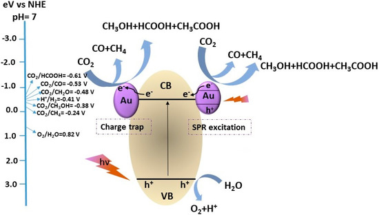
Scheme 1.
Schematic illustration of different possible photocatalytic products formation during CO2 photoreduction with H2O over a heterogeneous photocatalyst and standard reduction potentials (V).
There are three main factors which play an important role in the photocatalytic process: solar light harvesting, separation of the photoproduced charges and surface reaction. Significant improvements have been achieved for optimization of the first 2 steps since they are based on the same issues as the widely studied for other photocatalytic applications, for example, solar driven water splitting. The major difference is the surface reaction of charge carriers [7,8]. In case of CO2 photoreduction, the surface reaction is very challenging due to severe competition with hydrogen evolution reaction (HER) in the presence of water, which is more abundant and preferentially adsorbed onto the catalyst surfaces than CO2 [9,10]. Hence, design and fabrication of efficient photocatalysts for CO2 reduction is the aim of several studies [7,10,11,12,13].
TiO2, as a low-cost semiconductor, resistant to photo-corrosion, has been widely studied for the adsorption, photoinduced activation and reduction of CO2 [14,15,16,17]. He et al. proved that the anatase (101) facet played a critical role in CO2 adsorption and assisting the electron transfer from the surface of TiO2 to CO2 in the photoreduction process [18,19]. Besides, TiO2, shows favourable behaviour toward generating and separating electron–hole pairs during photoexcitation [16]. However, in order to improve the catalyst efficiency, decreasing the band gap and the fast recombination rate of holes and electrons generated during the irradiation process are the main concerns. To overcome this problem, various approaches have been developed: (i) noble metals addition to TiO2 acting as electron sinks (e.g., Au, Cu, Ag, Pd) [20,21], (ii) the use of organic or inorganic hole scavengers (HS) to donate electrons to the valence band of the semiconductor preventing the accumulation of holes [11]. Even though the use of HS has been shown to enhance the rate of the photocatalytic process, the by-products forming in their presence have to be also considered [22]. Sodium sulphite was chosen because of its ability to be oxidized into sulphate by the photogenerated holes and because it is considered as a non-harmful, widely abundant compound [23].
The photoreduction reaction involves multiple proton-coupled electron transfer reactions and can lead to the formation of many different products, either in liquid phase: HCOOH, HCHO, CH3OH or in the gas phase: H2, CO, CH4, depending on the reaction pathways, which makes this process rather complex (Scheme 1). A comparative study has been also carried out between the reaction in gas or liquid phase, the latter being the most promising [24] and leading to a promising route for the storage of solar energy in form of organic molecules [25]. We have already reported an innovative high pressure photoreactor, operating up to 20 bar [26,27] to successfully improve CO2 solubility. In that investigation, we have demonstrated that the solubility of CO2 in water is greatly enhanced at increasing pressure. Furthermore, a significant increase of activity can be achieved by increasing temperature, likely speeding up the dark steps of the reaction. Of course, the increase of temperature decreases the concentration of dissolved CO2 but the effect of pressure is by far more significant, so that operation at 7 bar, 80 °C leads to ca. 0.1 mol% CO2 in liquid phase, whereas in ambient conditions the value is more than ca. 5 times lower [24]. According to the higher solubility, the increase of pressure boosted the productivity of liquid phase products (HCOOH, HCHO and CH3OH, depending on catalyst formulation and conditions). Too high pressure depressed the productivity in the gas phase. Thus, operation at intermediate pressure (ca. 7 bar) allows to evidence the effect of the operating parameter on the whole spectrum of products.
This work reports a comprehensive study on CO2 photoreduction according to several variables. The reaction pathways and, thus, the control on products formation can be tuned by acting on different reaction parameters (e.g., pH, catalyst concentration and the amount of HS). Furthermore, improving the light harvesting capacity of TiO2 by doping with Au nanoparticles, which also act as electron sinks, affected both productivity and products distribution. The photocatalytic activity of TiO2 samples obtained by different preparation routes has been also investigated.
The specific configuration of the photoreactor suites the appropriate light distribution in the whole area. The very high productivity of H2 and HCOOH even with bare P25 photocatalyst, with respect to previous studies on TiO2 base photocatalyst, confirms the efficiency of our photoreactor.
2. Results and Discussion
2.1. Materials Characterization
The XRD pattern (Figure 1) of TiO2 sample obtained by flame pyrolysis shows a mixture of the crystalline phases of anatase and rutile with similar composition and particle size with respect to P25 samples (Table 1). All the diffraction features were identified by comparison with the standard JCPDS spectrum of rutile (file 88-1175) and anatase (file 84-1286) [28]. The phase composition and the average particle of each sample have been estimated from the intensity ratio between the reflection of anatase and rutile planes at (101) and (110) respectively (Table 1) [29]. The particle size of TiO2 samples has been calculated by using the Scherrer’s equation [30].
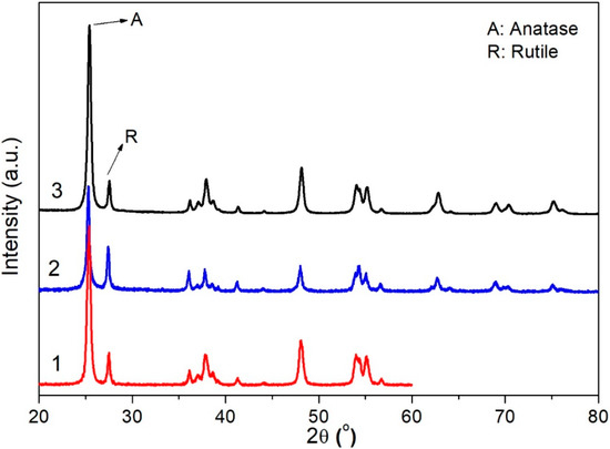
Figure 1.
XRD patterns of P25 (1), 0.2 wt% Au-P25 (2) and FSP (3). A and R stand for anatase and rutile phases, respectively.

Table 1.
Some relevant properties of the samples, as derived by N2 sorption isotherms at −196 °C, XRD patterns and Band gap calculation from DR UV-Vis data elaborated according to Tauc plots.
The BET SSA (Brunauer-Emmett-Teller Specific Surface Area) and pore volume have been determined based on N2 adsorption/desorption isotherms, collected at −196 °C for P25 and FSP samples, previously outgassed at 150 °C for 4 h (Figure 2). Micropore volume was calculated according to the t-plot method (Table 1). Both P25 and FSP samples show a type II isotherm with H1 hysteresis loop, representing the agglomerates or spherical particles arranged uniformly with high pore size uniformity and facile pore connectivity [31]. FSP samples, however, show higher surface area and pore volume with respect to P25, which may positively affect its catalytic performance. The surface area was not depressed by Au addition, given its very low amount. On the contrary, a slight increase of surface area even occurred during the chemical treatment of deposition, with a parallel increase of the total porosity of the sample with loss of microporosity.
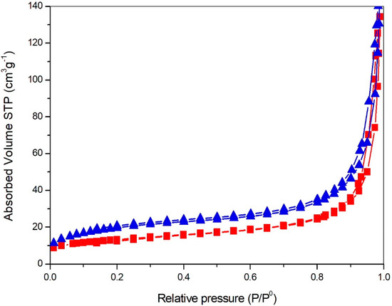
Figure 2.
N2 adsorption/desorption isotherms collected at −196 °C over samples outgassed overnight at 150 °C, P25 (squares), FSP (triangles).
According to UV absorption spectra (Figure 3a), both TiO2 and Au-TiO2 samples show an intense absorption in the spectral range between 240–380 nm, due to electron transfer from the 2p valence band orbital of O to the 3d conduction band orbital of Ti [32,33]. The spectra of un-doped TiO2 samples show the cut-off at shorter wavelengths, with respect to the doped samples. The main reason for the observed bathochromic shift in transition and the visible light absorption is due to changing of the energy levels of the semiconductor band gap through a charge transfer between the metal conduction band and the valence band or the d–d transition in the crystal field [30].
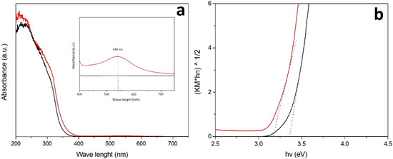
Figure 3.
DR UV-Vis spectra (a) and corresponding Tauc plots (b) of P25 (black curve) and promoted with Au (0.2 wt%; red curve).
In addition, the Au-TiO2 sample exhibits significantly enhanced light absorption in the visible region showing a broad band located between 450 and 600 nm typical of the Surface Plasmonic Resonance (SPR) of Au nanoparticles (NPs) (inset of Figure 3a). The broad visible light absorption range is possibly due to wide size distribution of Au-NPs and the maximum of the SPR band (λmax) intensity is mainly related to the size and content of Au particles.
The optical band gap energy Eg was determined according to the Tauc equation [34].
According to the Eg calculations (Figure 3b and Table 1) by promoting the TiO2 samples with Au, the absorption has been extended to longer wavelengths and the band gap energy reduced [32,35].
Au particle size distribution was determined from HRTEM and STEM images. Representative images are reported for 0.2 wt% Au-P25 with the respective histogram in Figure 4, revealing very small particles with a fairly narrow size distribution. Mean Au particle size was 3.6 nm.
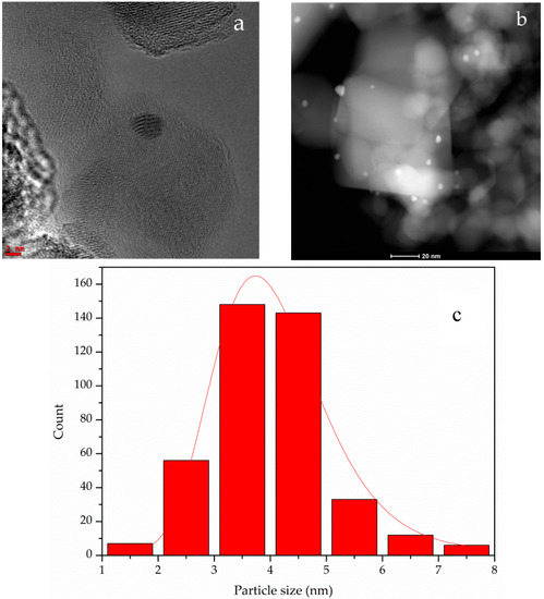
Figure 4.
Representative HRTEM (a) and STEM (b) images; particle size distribution (c). Sample 0.2 wt% Au-P25.
2.2. CO2 Photo-Reduction
2.2.1. Effect of pH
The photoreduction of CO2 may lead to a broad spectrum of products depending on photocatalyst formulation and reaction conditions, due to occurrence of many parallel and consecutive reaction steps [26,27,36].
The productivity and selectivity of products on P25 has been studied at pH 7.5 and 14 in the presence of 1.66 g L−1 HS (Figure 5). The productivity of the main products, HCOOH and H2, increased in basic pH in fair agreement with previous observations [26,37]. Increasing the pH improves the CO2 solubility by forming CO3− or HCO3−, which further reduced to HCOOH or HCHO in a series of subsequent reactions (Scheme 2). Furthermore, the formed liquid products may evolve to gas phase products (H2 and CO) due to the consecutive step of photo-reforming (Scheme 2) [26,37]. According to Ao et al. [38] in studies at basic pH, the back-oxidation of HCHO to HCOOH is more likely.
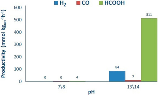
Figure 5.
Influence of pH over productivity. Reaction conditions: 0.5 g L−1 of P25, 1.66 g L−1 HS.
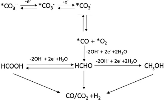
Scheme 2.
Consecutive pathways for CO2 photoreduction and photoreforming occurring at basic pH [37].
No methane formation has been observed, since P25 as a photocatalyst is likely to produce CO or HCOOH and is not likely to generate highly reduced hydrocarbons [39,40,41,42]. However, CO can be the precursor of methane formation following an alternative hydrogenation pathway [43].
Blank tests with the catalyst without irradiation and by irradiating without any catalyst revealed undetectable productivity to any species. A further photoreduction tests without pre-saturation with CO2, pressurizing with N2, led to nil concentration of organic products in liquid or gas phase, with a hydrogen productivity of 134.6 mmol H2 kgcat−1 h−1 due to the contribution of the direct water splitting, promoted by the presence of the hole scavenger. Therefore, it should be firmly remarked that the products formed in liquid phase are genuinely due to the reduction of CO2.
2.2.2. Effect of Catalyst Amount
Optimization of catalyst amount has been performed halving progressively the catalyst concentration (0.5, 0.25, 0.125, 0.064 and 0.031 g L−1) in the photoreactor by using the bare P25 catalyst. According to Figure 6, lower catalyst concentration increased productivity mainly due to better light distribution through the whole reactor. The productivity of the gas phase products (H2 and CO) and of HCOOH, either normalized per mass of catalyst (Figure 6a) or not (Figure 6b) allowed to assess the best catalyst concentration in the slurry. 0.031 g L−1 of P25 returned the highest amounts of H2 and HCOOH (Figure 6) per mass of catalyst. All the productivities decreased when increasing catalyst mass, as quite obvious due to the normalization on catalyst mass itself. When looking at the data without normalising against catalyst mass, the highest yield in HCOOH was obtained with the highest catalyst amount and progressively decreased with decreasing catalyst concentration. In a symmetric way, hydrogen and CO yields decreased progressively with increasing catalyst concentration (Figure 6b). Therefore, this parameter can be chosen to tune the process towards the maximisation of liquid or gas phase products, depending on process goals.
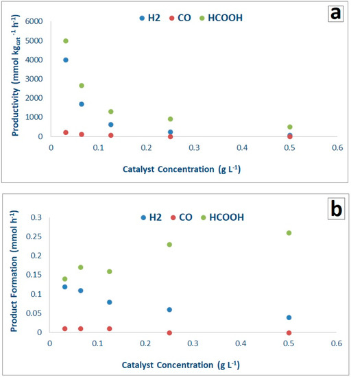
Figure 6.
Effect of catalyst concentration on productivity (a) and absolute product formation (b) with the P25 as a catalyst (1.66 g L−1 HS and at pH = 13/14).
0.031 g L−1 of catalyst was here taken as reference for further testing, so focusing on the highest gas phase productivity. Indeed, looking at the products distribution and intending this process as a mean to store solar energy by turning a waste greenhouse gas into useful compounds, we calculated the amount of energy stored in chemical form considering the different products we have obtained. We have taken as basis for calculation the enthalpy of combustion of HCOOH, H2 and CO and made the calculation for the two extreme cases of catalyst concentration 0.031 and 0.5 g L−1 (Table 2). The amount of energy that is stored is slightly higher for the highest catalyst concentration and increases progressively with this parameter. However, the form of storage is different, as well as the easiness of separation and exploitation, which is likely better in the case of gas products than for the diluted liquid product. It is therefore possible to operate obtaining the highest yield of gaseous products, at low catalyst concentration, or to increase the liquid product yield with higher catalyst amount. In the following, we selected to use the lowest catalyst concentration, since it is more amenable for scale up and it leads to a balanced production of gas and liquid phase compounds, that allow to highlight the effect of the other operating parameters on reactivity.
Table 2.
Amount of stored energy (kJ h−1) in the form of different reaction products.
Based on the maximum amount of energy stored as calculated in Table 2 and on the measured irradiance in the UVA region (104 W/m2), we calculated approximately 2–3% energy storage efficiency.
2.2.3. Effect of the Hole Scavenger (HS)
The efficiency of the photocatalyst is limited by the slow charge transfer, subsequent reactions of the photo-excited holes and the high charge recombination rates. In fact, consumption of conduction band electrons must be efficiently balanced by holes reduction. This process occurs in the presence of electron donor species; otherwise reaction rate is highly depressed.
Sodium sulphite (Na2SO3) was chosen as inorganic HS, added in different concentration (ca. 1.66, 3.34, 6.68 g L−1) and its consumption was determined after reaction by iodometric titration. Negligible productivity has been observed without HS addition. Sodium sulphite is an inorganic and non-competing species, with a high performance in photocatalytic reactions [23]. Moreover, sodium sulphite can be industrially employed due to its low cost.
Figure 7 reports that increasing the HS concentration from 1.66 to 6.68 g L−1 (4-fold increase) increases the HCOOH productivity up to 9 times, whereas clearly decreasing the formation of gas products (H2 and CO). The results of our previous studies already demonstrated that the formation of the gas phase products (H2, CO, CH4) starts after the consumption of the HS. Indeed, in absence of the sulphite the organic compounds accumulated in the reaction medium start acting as hole scavengers themselves through a consecutive photoreforming path (Scheme 2). Sulphites titration confirms the total consumption in 24 h of the base-case concentration 1.66 g L−1 (Figure 8). However, 24 h of reaction time were not enough for the total consumption of the HS when loaded in higher quantity (3.34 and 6.68 g L−1), which in turn inhibits the formation of gaseous products and favours the formation of HCOOH (Figure 8). This study supports the above proposed mechanism of the reaction and the role of HS (reaction time) on the selectivity to the different products.
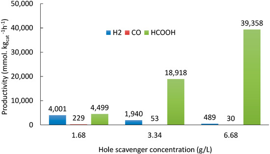
Figure 7.
Effect of HS concentration on productivity. Reaction time: 24 h. P25 as a photocatalyst (0.031 g L−1) and at pH = 13/14.
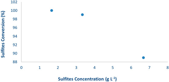
Figure 8.
Sulphite conversion vs. their initial concentration after 24 h of reaction. P25 as a photocatalyst with 0.031 g·L−1 loading and at pH = 13/14.
Moreover, according to Table 2, the boosted productivity to HCOOH, which is unprecedented in previous reports on this reaction, allows to tune also HS concentration, in addition to catalyst one, to address the reaction towards the desired products. It may be noticed, indeed, that the test with the highest HS concentration led to the highest amount of stored energy, which increased by one order of magnitude the stored energy amount even by increasing its concentration by a factor of 4, only. The choice of its use should be determined on the basis of the desired reaction path. The increase of HS makes photoreduction essentially more effective when leading to HCOOH. Its further transformation to H2 is inhibited until the complete consumption of the HS, leading to liquid phase products, only.
2.2.4. Comparison between Different Photocatalysts
Flame spray pyrolysis allows the synthesis of titanium dioxide nanoparticles characterized by high surface area and high thermal stability [43,44,45,46]. Due to the abundance of oxygen and high temperature in the FSP reactor, the nanoparticles produced by FSP are typically fully oxidized and highly crystalline. The simple synthesis procedure permits the rapid and continuous production of the catalyst.
FSP titanium dioxide prepared in our lab has been tested for comparison with the commercial P25 titania. The samples were compared using 1.66 g L−1 of HS, with the selected catalyst loading (0.031 g L−1) at 2 different pH conditions (Figure 9). Also in this case the conditions were selected to obtain significant amounts of products in both liquid and gas phase to check the effect of the other variables on both the mechanisms.
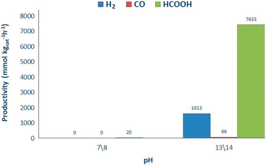
Figure 9.
Influence of pH over productivity (0.031 g L−1 of FSP and 1.66 g L−1 HS).
The results confirm also for the FSP titania a very limited productivity at neutral pH and a good productivity at basic pH. Slightly higher productivity of FSP has been partly attributed to its higher surface area (67 m2 g−1 for FSP, 45 m2 g−1 for P25), which increases the surface reactions rate, though being almost indifferent as for the main photochemical steps. Furthermore, the quite high activity of FSP and P25 catalysts has been attributed to the enhanced charge separation at the anatase-rutile interface which acts as charge traps (hence higher capacitance). This effect is much more remarkable for FSP at low catalyst loading, compared to the commercial TiO2 catalysts. According to previous studies [43,46], short flame residence time in extreme conditions, arising from high temperatures, may produce a metastable phase and also a small concentration of defect states in the bandgap due to a Ti4+ stoichiometry deficiency, thus, enabling electron-hole pair generation as well as acting as photocharge trap defects [47]. The enhanced photocatalytic performance of FSP catalyst has been confirmed when varying catalyst concentration, which may result in smaller average primary particles and agglomerates and decreases light scattering (Figure 10) [45]. These results imply that the flame spray pyrolysis is a promising technique to produce catalyst that can be employed industrially for this application. TiO2 P25 is also prepared through a flame synthesis, which however makes use of a different precursor and particle formation mechanism.
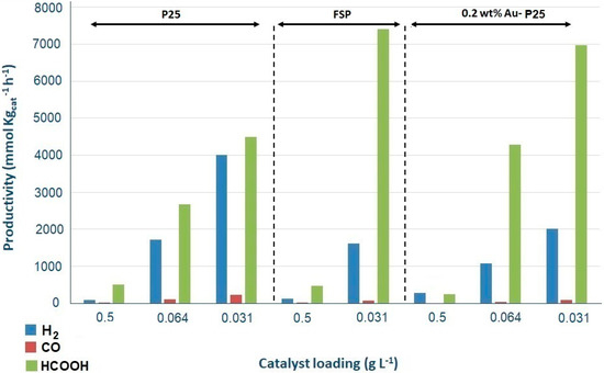
Figure 10.
Products productivity with respect to different catalysts in different loadings with HS = 1.66 g L−1 and at pH = 13/14.
Metals addition is a common strategy to improve visible light harvesting and to enhance the separation of photogenerated charges. We have investigated the performance of gold nanoparticles on the productivity and selectivity of products. 0.2 wt% Au loading was selected based on previous screening [37]. Au-P25 has been tested maintaining a fixed value of HS 1.66 g L−1, basic conditions (pH 13/14) and, also in this case, variable catalyst amount. Figure 10 reports the overall comparison of productivity of all the tested photocatalysts.
The comparison of different catalysts maintaining the highest catalyst concentration in the reactor (0.5 g L−1), demonstrates that adding gold to P25 increases the selectivity towards secondary products (hydrogen and CO) with respect to bare P25 and even FSP. The gold doped catalyst is characterized by higher visible light absorption, which positively affects the light harvesting ability and consequently the overall productivity. Furthermore, gold may act as electron trap to improve the charge separation efficiency. This increases the photocatalyst effectiveness for all the reaction steps depicted in the reaction schemes (vide supra).
CO can be either obtained by (i) direct photoreduction of CO2, or (ii) as a product of photoreforming of the organic compounds obtained in liquid phase by CO2 photoreduction, or even (iii) by catalytic reduction of CO2 by using the photogenerated H2. The productivity trend of CO and H2 are so similar to suggests that both species are produced by photoreforming of the primary organic products of photoreduction accumulated in the liquid phase.
On the contrary, for 0.2 wt% Au-P25 decreasing the catalyst concentration results in decreasing selectivity towards hydrogen production with respect to P25, balanced by a significant increase of the productivity to HCOOH (Figure 10). The enhancement of productivity is due to the strong electric fields created by the surface plasmon resonance of the Au nanoparticles, which excite electron-hole pairs locally in the TiO2 and produce a number of additional photocatalytic reaction products at a rate several orders of magnitude higher than the normal incident light [47]. In this wavelength range, both the excited electrons in Au and TiO2 contribute to the reduction of CO2 with H2O [47].
Overall, by calculating the amount of energy stored as in Table 2, there is no appreciable difference between the use of the FSP catalyst and the 0.2 wt% Au/P25 one, both being more efficient than P25 from this point of view.
Finally, Table 3 gives a comprehensive comparison of the different TiO2 based photocatalysts used for CO2 photoreduction and their productivity and selectivity, in comparison with the present work. The comparison with the relevant literature reports confirm the validity of the presently adopted high pressure photoreduction apparatus, which is able to outperform most results by various orders of magnitude.
Table 3.
Comparison of the photocatalytic performance for CO2 photoreduction of TiO2-based photocatalysts obtained with different techniques.
3. Experimental
3.1. Materials Preparation
TiO2 samples were prepared in dense nanoparticles form by FSP [44,62] and compared with a commercial P25 sample supplied by Evonik (code P25).
The FSP samples was prepared using a home-developed apparatus, composed of a burner which is co-fed with the titania precursor solution and 5 L/min of oxygen and the flame is ignited and sustained by a ring of flamelets (0.5 L/min CH4 + 1 L/min of O2). The solution of the oxide precursor in organic solvent is fed through a syringe pump at constant feeding rate of 2.5 mL/min in to the burner. The Titanium Isopropoxide (Sigma Aldrich, pur. 97%, St. Louis, MO, USA) as TiO2 precursor was dissolved in o-xylene and Propionic acid (Sigma Aldrich, pur. 97%, St. Louis, MO, USA) with a 0.4 M concentration and injected through the burner. The pressure drop at the burner nozzle was 1.5 bar.
The gold doped TiO2 samples (Au-P25) were prepared by a modified deposition-precipitation method using urea and a chemical reductant. 1 g of commercial TiO2 (Degussa P25, 45 m2 g−1) was dispersed in distilled water (100 mL) then 5 g of urea (Aldrich, >99%, St. Louis, MO, USA). NaAuCl4·2H2O solution (Aldrich, 99.99%, St. Louis, MO, USA) was added to the suspension and left under vigorous stirring for 4 h at 80 °C. The catalyst was filtered and washed several times with distilled water. The collected sample after first washing was suspended in distilled water and a freshly prepared solution 0.1 M of NaBH4 (Fluka, >96%, Bucharest, Romania) was added (NaBH4/Au = 4 mol/mol) under vigorous stirring at room temperature. The sample was filtered, washed and dried at 100 °C for 4 h. Atomic Absorption Spectroscopy (AAS) analysis (Perkin Elmer 3100 instrument, Champaign, IL, USA) was performed to assess the final composition of Au-P25 catalysts: 0.2 wt% Au-P25, which proved the most active in a preliminary catalyst screening [63].
3.2. Materials Characterization
X-ray diffraction (XRD) analyses were performed by the Rigaku D III-MAX horizontal-scan powder diffractometer (Tokyo, Japan) using Cu-Kα radiation with a graphite monochromator on the diffracted beam.
N2 adsorption and desorption isotherms of samples were collected with a Micromeritics ASAP2020 apparatus (Norcross, GA, USA).
Diffuse Reflectance (DR) UV-Vis spectra of samples were measured on a Cary 5000 UV-Vis-NIR spectrophotometer (Varian instruments, Santa Clara, CA, USA) in the range of 200–800 nm.
TPR analysis was carried out on a bench scale apparatus by flowing 40 mL/min of a 10 vol% H2/N2 mixture, while heating the sample by 10 °C/min up to 700 °C. The gas outflowing the quartz reactor was analysed with a TCD detector after entrapping the possibly formed water.
The TEM specimens were prepared by dispersing the catalyst powder on TEM grids coated with holey carbon film. They were examined in a FEI Titan 80–300 electron microscope equipped with CEOS image spherical aberration corrector, Fischione model 3000 high angle annular dark field (HAADF) scanning transmission electron microscopy (STEM) detector (Portland, OR, USA).
3.3. Photoreactor and Testing Conditions
All the experimental activity tests have been performed using an innovative pressurized batch photo-reactor which has been discussed in detail elsewhere [37,64,65]. The cylinder-shaped reactor made of AISI 316 stainless steel can operate up to 20 bar at temperatures up to 90 °C. The temperature is kept constant through a double-walled thermostatic system. The internal capacity of the reactor is ca. 1.3 L, filled with ca. 1.2 L solution. Continuous stirring inside the reactor is provided by a magnetic stirrer placed underneath up to 400 RPM to ensure the optimal dispersion of the catalyst in the liquid phase.
The radiation source is a medium-pressure 125 W Hg vapour lamp with a range of emission between 254 nm ≤ λ ≤ 364 nm, with maximum emission at this latter wavelength. An air circulation system has been used to cool the lamp. The power of irradiation directly depends on the flow rate of the cooling pressurized air. Therefore, the best cooling condition for the optimum lamp lifetime with the maximum irradiation power has been selected. The emitted power was periodically measured by means of a photoradiometer (Delta OHM HD2102.2, Padua, Italy) and corresponds to ca. 104 W m−2 at the bottom of the source.
For the optimization of the best amount of catalyst, several concentrations have been chosen (ca. 0.5, 0.25, 0.125, 0.064, 0.031 g L−1). The catalysts have been loaded with a suspension of bi-distilled water in the reactor. The best saturation condition has been settled overnight with the CO2 saturation pressure of 7 bar and temperature of 80 °C, based on previous studies [26,37]. Testing was carried out under the same conditions, if not otherwise specified. Such a pressure and temperature allow to obtain a broad products spectrum both in gas and liquid phase, so they were set as optimal to investigate the effect of other parameters on productivity and selectivity to all the products.
Na2SO3 has been used as HS in different amounts (ca. 1.66, 3.34, 6.68 g L−1) to understand its effect on productivity and selectivity to the various products. As expected, negligible productivity both in the liquid and in the gas phase has been observed without its addition. The photoreaction has been started by switching on the lamp for the 24 h of the reaction time.
Liquid products have been analysed by taking samples at the end of the reaction. For analysing the liquid products, HPLC (Agilent 1220 Infinity, with a column Alltech OA-10308, 300 mm_7.8 mm, Palo Alto, CA, USA), equipped with both UV and refractive index (Agilent 1260 Infinity, Palo Alto, CA, USA) detectors have been used. Aqueous H3PO4 solution (0.1 wt%) was used as the eluent. The gas products were collected in the headspace of the photoreactor and analysed by a gas chromatograph (Agilent 7890, Palo Alto, CA, USA) equipped with a TCD detector with the proper set up configuration for the quantification of H2, CH4 and polar/non-polar light gases.
4. Conclusions
The high pressure photoreduction of CO2 in water has been studied under different operating conditions, investigating the role of catalyst concentration, varying the amount of hole scavenger and the effect of adding gold on productivity and selectivity. A comparison between different flame-based techniques for the preparation of TiO2 was also done, that is, TiO2 prepared by FSP and P25.
The hole scavenger plays a crucial role in the selective formation of gas products (CO and H2) in the course of reaction time. In the presence of HS, photoreduction has been obtained in the liquid phase by formation of HCOOH as a main product. The consumption of the HS, instead, results in the consecutive photoreforming of the organic compounds accumulated in the liquid phase, with formation of secondary products, H2 and CO, in the gas phase.
0.2 wt%-Au-P25 and TiO2-FSP showed higher productivity for HCOOH with respect to TiO2-P25. The method of synthesizing FSP nanoparticles may results in formation of metastable phase and defects which can further enhance the electron-hole pair generation and increasing the lifetime of photogenerated charges. Instead, the surface Plasmon resonance effect by doping Au on P25 can be considered as a main reason for higher HCOOH productivity in the presence of 0.2 wt%-Au-P25, with respect to bare TiO2 P25.
Overall, appreciable amounts of energy per unit time have been stored through this reaction. The operating conditions should be tuned in order to drive the reaction towards the maximization of energy storage (high catalyst and HS concentrations) or the selection of the desired products.
Author Contributions
E.B. and A.T. Investigation, Data Curation, Writing-Original Draft Preparation; A.V. Investigation, Data Curation; C.P. Writing-Review & Editing; L.P. and G.R. Supervision, Project Administration, Funding Acquisition; I.R. Supervision, Project Administration, Funding Acquisition, Writing-Review & Editing.
Funding
This research was funded by Fondazione Cariplo and Regione Lombardia, grant number 2016-0858–“Up-Unconventional Photoreactors” and by MIUR through the PRIN2015 grant (20153T4REF).
Acknowledgments
The valuable help of the graduating student M.F. and of W.W. is gratefully acknowledged. We acknowledge Karlsruhe Nano Micro Facility for TEM.
Conflicts of Interest
The authors declare no conflict of interest.
References
- Centi, G.; Perathoner, S. Opportunities and prospects in the chemical recycling of carbon dioxide to fuels. Catal. Today 2009, 148, 191–205. [Google Scholar] [CrossRef]
- Jessop, G.P.; Ikariya, T.; Noyori, R. Homogeneous catalytic hydrogenation of supercritical carbon dioxide. Nature 1994, 368, 231–233. [Google Scholar] [CrossRef]
- Olajire, A.A. Valorization of greenhouse carbon dioxide emissions into value-added products by catalytic processes. J. CO2 Util. 2013, 3–4, 74–92. [Google Scholar] [CrossRef]
- Wang, W.; Soulis, J.; Yang, Y.J.; Biswas, P. Comparison of CO2 Photoreduction Systems: A Review. Aerosol Air Qual. Res. 2014, 14, 533–549. [Google Scholar] [CrossRef]
- Yuan, L.; Xu, Y.-J. Photocatalytic conversion of CO2 into value-added and renewable fuels. Appl. Surf. Sci. 2015, 342, 154–167. [Google Scholar] [CrossRef]
- Linsebigler, A.L.; Lu, G.; Yates, J.T. Photocatalysis on TiO2 Surfaces: Principles, Mechanisms, and Selected Results. Chem. Rev. 1995, 95, 735–758. [Google Scholar] [CrossRef]
- Li, X.; Wen, J.; Low, J.; Fang, Y.; Yu, J. Design and fabrication of semiconductor photocatalyst for photocatalytic reduction of CO2 to solar fuel. Sci. China Mater. 2014, 57, 70–100. [Google Scholar] [CrossRef]
- Chang, X.; Wang, T.; Zhang, P.; Zhang, J.; Li, A.; Gong, J. Enhanced Surface Reaction Kinetics and Charge Separation of p–n Heterojunction Co3O4/BiVO4 Photoanodes. J. Am. Chem. Soc. 2015, 137, 8356–8359. [Google Scholar] [CrossRef] [PubMed]
- Zhai, Q.; Xie, S.; Fan, W.; Zhang, Q.; Wang, Y.; Deng, W.; Wang, Y. Photocatalytic Conversion of Carbon Dioxide with Water into Methane: Platinum and Copper(I) Oxide Co-catalysts with a Core-Shell Structure. Angew. Chem. 2013, 52, 5776–5779. [Google Scholar] [CrossRef] [PubMed]
- White, J.L.; Baruch, M.F.; Pander, J.E.; Hu, Y.; Fortmeyer, I.C.; Park, J.E.; Zhang, T.; Liao, K.; Gu, J.; Yan, Y.; et al. Light-Driven Heterogeneous Reduction of Carbon Dioxide: Photocatalysts and Photoelectrodes. Chem. Rev. 2015, 115, 12888–12935. [Google Scholar] [CrossRef] [PubMed]
- Habisreutinger, S.N.; Schmidt-Mende, L.; Stolarczyk, J.K. Photocatalytic Reduction of CO2 on TiO2 and Other Semiconductors. Angew. Chem. Int. Ed. 2013, 52, 7372–7408. [Google Scholar] [CrossRef] [PubMed]
- Xie, S.; Zhang, Q.; Liu, G.; Wang, Y. Photocatalytic and photoelectrocatalytic reduction of CO2 using heterogeneous catalysts with controlled nanostructures. Chem. Commun. 2015, 52, 35–59. [Google Scholar] [CrossRef] [PubMed]
- Ma, Y.; Wang, X.; Jia, Y.; Chen, X.; Han, H.; Li, C. Titanium Dioxide-Based Nanomaterials for Photocatalytic Fuel Generations. Chem. Rev. 2014, 114, 9987–10043. [Google Scholar] [CrossRef] [PubMed]
- Indrakanti, V.P.; Kubicki, J.D.; Schobert, H.H. Photoinduced activation of CO2 on Ti-based heterogeneous catalysts: Current state, chemical physics-based insights and outlook. Energy Environ. Sci. 2009, 2, 745. [Google Scholar] [CrossRef]
- Gattrell, M.; Gupta, N.; Co, A. A review of the aqueous electrochemical reduction of CO2 to hydrocarbons at copper. J. Electroanal. Chem. 2006, 594, 1–19. [Google Scholar] [CrossRef]
- Michalkiewicz, B.; Majewska, J.; Ka, G.; Bubacz, K.; Mozia, S.; Morawski, A.W. Reduction of CO2 by adsorption and reaction on surface of TiO2-nitrogen modified photocatalyst. J. CO2 Util. 2014, 5, 47–52. [Google Scholar] [CrossRef]
- Izumi, Y. Recent advances (2012–2015) in the photocatalytic conversion of carbon dioxide to fuels using solar energy: Feasibilty for a new energy. ACS Symp. Ser. 2015, 1194, 1–46. [Google Scholar]
- He, H.; Zapol, P.; Curtiss, L.A. A Theoretical Study of CO2 Anions on Anatase (101) Surface. J. Phys. Chem. C 2010, 114, 21474–21481. [Google Scholar] [CrossRef]
- He, H.; Zapol, P.; Curtiss, L.A. Computational screening of dopants for photocatalytic two-electron reduction of CO2 on anatase (101) surfaces. Energy Environ. Sci. 2012, 5, 6196–6205. [Google Scholar] [CrossRef]
- Chen, B.-R.; Nguyen, V.-H.; Wu, J.C.S.; Martin, R.; Kočí, K. Production of renewable fuels by the photohydrogenation of CO2: Effect of the Cu species loaded onto TiO2 photocatalysts. Phys. Chem. Chem. Phys. 2016, 18, 4942–4951. [Google Scholar] [CrossRef] [PubMed]
- Koci, K.; Matteju, K.; Obalovà, L.; Krejcikovà, S.; Lacny, Z.; Plachà, D.; Capek, L.; Hospodkovà, A.; Solcovà, O. Effect of silver doping on the TiO2 for photocatalytic reduction of CO2. Appl. Catal. B Environ. 2010, 96, 239–244. [Google Scholar] [CrossRef]
- Li, K.; An, X.; Hyeon, K.; Khraisheh, M.; Tang, J. A critical review of CO2 photoconversion: Catalysts and reactors. Catal. Today 2014, 224, 3–12. [Google Scholar] [CrossRef]
- Chen, X.; Shen, S.; Guo, L.; Mao, S.S. Semiconductor-based Photocatalytic Hydrogen Generation. Chem. Rev. 2010, 110, 6503–6570. [Google Scholar] [CrossRef] [PubMed]
- Rossetti, I.; Villa, A.; Compagnoni, M.; Prati, L.; Ramis, G.; Pirola, C.; Bianchi, C.L.; Wang, W.; Wang, D. CO2 photoconversion to fuels under high pressure: Effect of TiO2 phase and of unconventional reaction conditions. Catal. Sci. Technol. 2015, 5, 4481–4487. [Google Scholar] [CrossRef]
- Rossetti, I.; Villa, A.; Pirola, C.; Prati, L.; Ramis, G. A novel high-pressure photoreactor for CO2 photoconversion to fuels. RSC Adv. 2014, 4, 28883–28885. [Google Scholar] [CrossRef]
- Olivo, A.; Ghedini, E.; Signoretto, M.; Compagnoni, M.; Rossetti, I. Liquid vs. Gas Phase CO2 Photoreduction Process: Which Is the Effect of the Reaction Medium? Energies 2017, 10, 1394. [Google Scholar] [CrossRef]
- Rossetti, I.; Bahadori, E.; Tripodi, A.; Villa, A.; Prati, L.; Ramis, G. Conceptual design and feasibility assessment of photoreactors for solar energy storage. Sol. Energy 2018. [Google Scholar] [CrossRef]
- Spurr, R.A.; Myers, H. Quantitative Analysis of Anatase-Rutile Mixtures with an X-ray Diffractometer. Anal. Chem. 1957, 29, 760–762. [Google Scholar] [CrossRef]
- Chauhan, R.; Kumar, A.; Chaudhary, R.P. Structural and optical characterization of Ag-doped TiO2 nanoparticles prepared by a sol–gel method. Res. Chem. Intermed. 2012, 38, 1443–1453. [Google Scholar] [CrossRef]
- Thommes, M.; Kaneko, K.; Neimark, A.V.; Olivier, J.P.; Rodriguez-reinoso, F.; Rouquerol, J.; Sing, K.S.W. Physisorption of gases, with special reference to the evaluation of surface area and pore size distribution (IUPAC Technical Report). Pure Appl. Chem. 2015, 87, 1051–1069. [Google Scholar] [CrossRef]
- Seifvand, N.; Kowsari, E. Synthesis of Mesoporous Pd-Doped TiO2 Templated by a Magnetic Recyclable Ionic Liquid for Efficient Photocatalytic Air Treatment. Ind. Eng. Chem. Res. 2016, 55, 10533–10543. [Google Scholar] [CrossRef]
- Tan, S.T.; Chen, B.J.; Sun, X.W. Blueshift of optical band gap in ZnO thin films grown by metal-organic chemical-vapour deposition. J. Appl. Phys. 2005, 98, 013505. [Google Scholar] [CrossRef]
- Li, P.; Hu, H.; Xu, J.; Jing, H.; Peng, H.; Lu, J. New insights into the photo-enhanced electrocatalytic reduction of carbon dioxide on MoS2-rods/TiO2 NTs with unmatched energy band. Appl. Catal. B Environ. 2014, 147, 912–919. [Google Scholar] [CrossRef]
- Mogal, S.I.; Gandhi, V.G.; Mishra, M.; Tripathi, S.; Shripathi, T.; Joshi, P.; Shah, D.O. Single-Step Synthesis of Silver-Doped Titanium Dioxide: Influence of Silver on Structural, Textural, and Photocatalytic Properties. Ind. Eng. Chem. Res. 2014, 53, 5749–5758. [Google Scholar] [CrossRef]
- Izumi, Y. Recent advances in the photocatalytic conversion of carbon dioxide to fuels with water and/or hydrogen using solar energy and beyond. Coord. Chem. Rev. 2013, 257, 171–186. [Google Scholar] [CrossRef]
- Ao, C.H.; Lee, S.C.; Yu, J.Z.; Xu, J.H. Photodegradation of formaldehyde by photocatalyst TiO2: Effects on the presences of NO, SO2 and VOCs. Appl. Catal. B Environ. 2004, 54, 41–50. [Google Scholar] [CrossRef]
- Galli, I.R.F.; Compagnoni, M.; Vitali, D.; Pirola, C.; Bianchi, C.L.; Villa, A.; Prati, L. CO2 photoreduction at high pressure to both gas and liquid products over titanium dioxide. Appl. Catal. B Environ. 2017, 200, 386–391. [Google Scholar] [CrossRef]
- Shen, J.; Kortlever, R.; Kas, R.; Birdja, Y.Y.; Diaz-morales, O.; Kwon, Y.; Ledezma-yanez, I.; Schouten, K.J.P.; Mul, G.; Koper, M.T.M. Electrocatalytic reduction of carbon dioxide to carbon monoxide and methane at an immobilized cobalt. Nat. Commun. 2015, 6, 1–8. [Google Scholar] [CrossRef] [PubMed]
- Weng, Z.; Jiang, J.; Wu, Y.; Wu, Z.; Guo, X.; Materna, K.L.; Liu, W.; Batista, V.S.; Brudvig, G.W.; Wang, H. Electrochemical CO2 Reduction to Hydrocarbons on a Heterogeneous Molecular Cu Catalyst in Aqueous Solution. J. Am. Chem. Soc. 2016, 138, 8076–8079. [Google Scholar] [CrossRef] [PubMed]
- Manthiram, K.; Beberwyck, B.J.; Alivisatos, A.P. Enhanced Electrochemical Methanation of Carbon Dioxide with a Dispersible Nanoscale Copper Catalyst. J. Am. Chem. Soc. 2014, 136, 13319–13325. [Google Scholar] [CrossRef] [PubMed]
- Xie, M.S.; Xia, B.Y.; Li, Y.; Yan, Y.; Yang, Y.; Sun, Q.; Chan, S.H.; Fishere, A.; Wang, X. Amino acid modified copper electrodes for the enhanced selective electroreduction of carbon dioxide towards hydrocarbons. Energy Environ. Sci. 2016, 9, 1687–1695. [Google Scholar] [CrossRef]
- Kočí, K.; Obalová, L.; Matějová, L.; Plachá, D.; Lacný, Z.; Jirkovský, J.; Šolcová, O. Effect of TiO2 particle size on the photocatalytic reduction of CO2. Appl. Catal. B Environ. 2009, 89, 494–502. [Google Scholar] [CrossRef]
- Teoh, W.Y. A Perspective on the Flame Spray Synthesis of Photocatalyst Nanoparticles. Materials 2013, 6, 3194–3212. [Google Scholar] [CrossRef] [PubMed]
- Compagnoni, M.; Lasso, J.; di Michele, A.I.; Rossetti, I. Flame-pyrolysis-prepared catalysts for the steam reforming of ethanol. Catal. Sci. Technol. 2016, 6, 6247–6256. [Google Scholar] [CrossRef]
- Giacomo, L.; Maria, B.; Diamanti, V.; Sansotera, M.; Pia, M.; Walter, P.; Paolo, N. Immobilized TiO2 nanoparticles produced by flame spray for photocatalytic water remediation. J. Nanopart. Res. 2016, 18, 238. [Google Scholar]
- Bettini, L.; Dozzi, M.; della Foglia, F.; Chiarello, G.; Selli, E.; Lenardi, C.; Piseri, P.; Milani, P. Mixed-phase nanocrystalline TiO2 photocatalysts produced by flame spray pyrolysis. Appl. Catal. B Environ. 2015, 178, 226. [Google Scholar] [CrossRef]
- Yu, J.; Low, J.; Xiao, W.; Zhou, P.; Jaroniec, M. Enhanced Photocatalytic CO2 Reduction Activity of Anatase TiO2 by Coexposed {001} and {101} Facets. J. Am. Chem. Soc. 2014, 136, 8839–8842. [Google Scholar] [CrossRef] [PubMed]
- Liu, L.; Zhao, C.; Li, Y. Spontaneous Dissociation of CO2 to CO on Defective Surface of Cu(I)/TiO2−x Nanoparticles at Room Temperature. J. Phys. Chem. C 2012, 116, 7904–7912. [Google Scholar] [CrossRef]
- Meng, X.; Ouyang, S.; Kako, T.; Li, P.; Yu, Q.; Wang, T.; Ye, J. TiO2 without loading noble metal cocatalyst. Chem. Commun. 2014, 50, 11517–11519. [Google Scholar] [CrossRef] [PubMed]
- Xie, S.; Wang, Y.; Zhang, Q.; Fan, W.; Deng, W.; Wang, Y. Photocatalytic reduction of CO2 with H2O: Significant enhancement of the activity of Pt–TiO2 in CH4 formation by addition of MgO. Chem. Commun. 2013, 49, 2451–2453. [Google Scholar] [CrossRef] [PubMed]
- Liao, Y.; Cao, S.; Yuan, Y.; Gu, Q.; Zhang, Z.; Xue, C. Efficient CO2 Capture and Photoreduction by Amine-Functionalized TiO2. Chem. Eur. J. 2014, 20, 10220–10222. [Google Scholar] [CrossRef] [PubMed]
- Nasution, H.W.; Purnama, E.; Kosela, S.; Gunlazuardi, J. Photocatalytic reduction of CO2 on copper-doped Titania catalysts prepared by improved-impregnation method. Catal. Commun. 2005, 6, 313–319. [Google Scholar] [CrossRef]
- Ishitani, O.; Inoue, C.; Suzuki, Y.; Ibusuki, T. Photocatalytic reduction of carbon dioxide to methane and acetic acid by an aqueous suspension of metal-deposited TiO2. J. Photochem. Photobiol. A Chem. 1993, 72, 269–271. [Google Scholar] [CrossRef]
- Wang, W.; An, W.; Ramalingam, B.; Mukherjee, S.; Niedzwiedzki, D.M.; Gangopadhyay, S.; Biswas, P. Size and Structure Matter: Enhanced CO2 Photoreduction Efficiency by Size-Resolved Ultrafine Pt Nanoparticles on TiO2 Single Crystals. J. Am. Chem. Soc. 2012, 134, 11276–11281. [Google Scholar] [CrossRef] [PubMed]
- Wang, P.Q.; Bai, Y.; Liu, J.Y.; Fan, Z.; Hu, Y.Q. One-pot synthesis of rutile TiO2 nanoparticle modified anatase TiO2 nanorods toward enhanced photocatalytic reduction of CO2 into hydrocarbon fuels. Catal. Commun. 2012, 29, 185–188. [Google Scholar] [CrossRef]
- Liu, S.; Zhao, Z.; Wang, Z. Photocatalytic reduction of carbon dioxide using sol–gel derived titania-supported CoPc catalysts. Photochem. Photobiol. Sci. 2007, 6, 695–700. [Google Scholar] [CrossRef] [PubMed]
- Tseng, I.-H.; Wu, J.C.S.; Chou, H.-Y. Effects of sol–gel procedures on the photocatalysis of Cu/TiO2 in CO2 photoreduction. J. Catal. 2004, 221, 432–440. [Google Scholar] [CrossRef]
- Tseng, I.-H.; Chang, W.-C.; Wu, J.C.S. Photoreduction of CO2 using sol–gel derived titania and titania-supported copper catalysts. Environ. Appl. Catal. B 2002, 37, 37–48. [Google Scholar] [CrossRef]
- Kaneco, S.; Kurimoto, H.; Shimizu, Y.; Ohta, K. Photocatalytic reduction of CO2 using TiO2 powders in supercritical fluid CO2. Energy 1999, 24, 21–30. [Google Scholar] [CrossRef]
- Kohno, Y.; Hayashi, H.; Takenaka, S.; Tanaka, T.; Funabiki, T.; Yoshida, S. Photo-enhanced reduction of carbon dioxide with hydrogen over Rh/TiO2. J. Photochem. Photobiol. A Chem. 1999, 126, 117–123. [Google Scholar] [CrossRef]
- Kaneco, S.; Shimizu, Y.; Ohta, K.; Mizuno, T. Photocatalytic reduction of high pressure carbon dioxide using TiO2 powders with a positive hole scavenger. J. Photochem. Photobiol. A Chem. 1998, 115, 223–226. [Google Scholar] [CrossRef]
- Chiarello, G.L.; Rossetti, I.; Forni, L. Flame-spray pyrolysis preparation of perovskites for methane catalytic combustion. J. Catal. 2005, 236, 251–261. [Google Scholar] [CrossRef]
- Compagnoni, M.; Kondrat, S.A.; Chan-Thaw, C.E.E.; Morgan, D.J.; Wang, D.; Prati, L.; Dimitratos, N.; Rossetti, I. Spectroscopic Investigation of Titania Supported Gold Nanoparticles Prepared by a Modified DP Method for the Oxidation of CO. ChemCatChem 2016, 8, 2136–2145. [Google Scholar] [CrossRef]
- Thamaphat, K.; Limsuwan, P.; Ngotawornchai, B. Phase Characterization of TiO2 Powder by XRD and TEM. Conf. Proc. 2008, 361, 357–361. [Google Scholar]
- Compagnoni, M.; Ramis, G.; Freyria, F.S.; Armandi, M.; Bonelli, B.; Rossetti, I. Innovative photoreactors for unconventional photocatalytic processes: The photoreduction of CO2 and the photo-oxidation of ammonia. Rend. Lincei 2017, 28, 151–158. [Google Scholar] [CrossRef]
© 2018 by the authors. Licensee MDPI, Basel, Switzerland. This article is an open access article distributed under the terms and conditions of the Creative Commons Attribution (CC BY) license (http://creativecommons.org/licenses/by/4.0/).