Article

Effect of Support Pretreatment Temperature on the Performance of an Iron Fischer–Tropsch Catalyst Supported on Silica-Stabilized Alumina

1
Department of Chemical Engineering, Brigham Young University, Provo, UT 84602, USA
2
Department of Chemistry and Biochemistry, Brigham Young University, Provo, UT 84602, USA
3
Department of Physics, Wichita State University, Wichita, KS 67260, USA
*
Author to whom correspondence should be addressed.
Catalysts 2018, 8(2), 77; https://doi.org/10.3390/catal8020077
Submission received: 12 December 2017 / Revised: 26 January 2018 / Accepted: 29 January 2018 / Published: 12 February 2018

Abstract

:
The effect of support material pretreatment temperature, prior to adding the active phase and promoters, on Fischer–Tropsch activity and selectivity was explored. Four iron catalysts were prepared on silica-stabilized alumina (AlSi) supports pretreated at 700 °C, 900 °C, 1100 °C or 1200 °C. Addition of 5% silica to alumina made the AlSi material hydrothermally stable, which enabled the unusually high support pretreatment temperatures (>900 °C) to be studied. High-temperature dehydroxylation of the AlSi before impregnation greatly reduces FeO·Al2O3 surface spinel formation by removing most of the support-surface hydroxyl groups leading to more effectively carbided catalyst. The activity increases more than four-fold for the support calcined at elevated temperatures (1100–1200 °C) compared with traditional support calcination temperatures of <900 °C. This unique pretreatment also facilitates the formation of ε′-Fe2.2C rather than χ-Fe2.5C on the AlSi support, which shows an excellent correlation with catalyst productivity.

Graphical Abstract

1. Introduction

Fisher–Tropsch synthesis (FTS) is a catalytic process that converts carbon sources like natural gas, coal and biomass into more valuable hydrocarbon fuels. Traditionally, the FTS industry uses supported cobalt and unsupported iron catalysts [1,2]. Iron catalysts are preferred over cobalt for FTS from coal or biomass because of their low cost, low methane selectivity and high water–gas shift (WGS) activity; WGS activity is needed for internal production of H2 during FTS because of inherently low H2/CO ratios of syngas produced from coal or biomass. Unsupported iron FT catalysts are limited by their weak mechanical strength making them a poor option for slurry-bubble column reactors, the most thermally efficient and economical FT reactors [3]. Unfortunately, supported iron FT catalysts have historically had poor activities and selectivities making them commercially unavailable [4,5,6]. Potassium and copper are structural promoters often used in industrial iron FT catalysts. It is widely accepted that potassium suppresses methane formation and increases the formation rate of heavy hydrocarbons [7,8,9]. On the other hand, copper reduces the temperature required for the reduction of iron oxides through enhanced H2 dissociation [7,8,10].
The relatively poor performance of supported iron FTS catalysts is primarily attributed to the strong Fe oxide-support interactions [6,11]. The effect of inorganic oxide supports (Al2O3, SiO2, TiO2 and ZrO2) have been tested for iron based FTS [12,13,14]; it was shown that catalysts’ activity and selectivity are greatly affected by support-surface acidity and catalyst-support interaction. To decrease Fe oxide–support interactions a variety of carbon supports (for example carbon nanotubes, nanofibers, carbon spheres or activated carbon), which provide inert surface chemistry, have also been studied [15,16,17,18,19,20].
Of all the studies on supported Fe catalyst, there has been limited focus on the effects of support pretreatment methods, prior to adding the active phase and promoters [12]. On the other hand, some studies have been undertaken on the effect of support type and support pore sizes [11,18,21,22]. Among the few studies on the effect of support pretreatment, Xu and Bartholomew prepared 10% Fe/silica catalyst via non-aqueous evaporative impregnation of a silica support, where the support was dehydroxylated at 600 °C before Fe impregnation [6]. This was done using a non-aqueous solvent to decrease any further metal oxide–support interactions. Even with the careful catalyst preparation, interaction of metal oxide and the silica support was high which resulted in low catalyst activity. It could be expected that the supports with high interaction with metals could provide higher stability by preventing the agglomeration of metal particles [21]. On the other hand, strong metal oxide–support interaction could lead to inactive species which are very difficult to reduce or to carbidize [11]. Weak interactive supports such as activated carbon have been also modified with functional surface groups to increase interaction between support and iron species [23].
Calcination of supports at high temperatures is a pathway to make reducible iron catalysts. However, the calcination temperature is usually limited to 500–800 °C due to the limited hydrothermal stability of typical supports, such as alumina and silica. Qu et al. showed higher dispersion of Ag on silica and, subsequently, higher CO oxidation activity as the support was pretreated at 550–700 °C [24]. Higher calcination temperatures (900–950 °C) of the support resulted in an agglomeration of Ag particles due to a drastic decrease in surface area and pore volume of the support with calcination temperature. However, our group has recently reported a hydrothermally stable γ-alumina doped with 5 wt % silica. Silica enters the tetrahedral vacancies in the defect spinel structure of alumina and forms Si–Al spinel phase, which significantly postpones the alumina phase transition from γ to α even at temperatures as high as 1200 °C [25,26]. This unique feature enables pretreatment of the AlSi support at much higher temperatures than conventionally practiced for catalyst preparation and makes it a unique support for FT iron catalyst [27].
In this paper, we explore the effect of support pretreatment temperature on the catalytic performance of iron catalysts supported on AlSi. The hydrothermal stability of the AlSi support enabled us, for the first time, to pretreat the support at high temperatures (1100–1200 °C) while still maintaining the γ-alumina phase with high surface area and large pore volume. High-temperature dehydroxylation of the AlSi facilitates the formation of ε′-Fe2.2C, which resulted in a very active supported iron catalyst.

2. Results

2.1. Physical Properties

2.1.1. Nitrogen Adsorption

Nitrogen adsorption measurements were conducted on both the supports and final catalysts to determine the pore properties. Table 1 summarizes the surface areas, pore volumes and average pore diameters, while their pore size distributions are shown in Figure 1. As shown in Table 1, surface area and pore volume of the supports decrease as the pretreatment temperature increases from 700 °C to 1200 °C, i.e., surface area decreases from 331 m2/g to 76 m2/g and pore volume decreases from 1.75 cm3/g to 0.52 cm3/g. Similarly, the same trend for surface area is observed for the final catalysts. However, drastic differences for pore volume of the supports and the corresponding catalysts are found. The pore volumes of the catalysts in which the supports were pretreated at 700 °C and 900 °C are less than that of the catalysts with supports pretreated at 1100 °C. The pore size distribution of each support is very similar and the average pore diameter is about 22 nm, as shown in Figure 1a. However, once Fe was loaded on to each support, the pore size distribution was quite different for the final catalysts (Figure 1b). Average pore diameter is decreased significantly for Fe/700AlSi and Fe/900AlSi by 72% and 51%, respectively, while the average pore diameter is decreased for Fe/1100AlSi and Fe/1200AlSi by only 10% and 12%, respectively. Moreover, the pore diameters of the final catalysts, by which the support was calcined at lower temperatures (Fe/700AlSi and Fe/900AlSi), were much lower than those catalysts calcined at higher temperatures (Fe/1100AlSi and Fe/1200AlSi) (5–11 nm vs. 21 nm).

2.1.2. X-ray Diffraction (XRD)

Figure 2 shows the X-ray diffraction (XRD) patterns of the freshly reduced and carbided catalysts. Fe3O4 and Fe metal are present in the freshly reduced catalysts (Figure 2a); however, the peak intensities are different for each catalyst. Fe/1100AlSi has the lowest Fe3O4/Fe ratio, while the highest ratio of Fe3O4/Fe is observed in Fe/700AlSi. Particle sizes for Fe3O4 and Fe0 were calculated based on peaks at 2θ = 37.6° and 45.8°, respectively (Table 2). Iron particle sizes are relatively large (>35 nm) when the support is calcined at 700–900 °C; however, the lowest particles sizes (4–8 nm) result with 1100AlSi support. The iron particle sizes are slightly increased when the support is calcined at higher temperatures of 1200 °C. The iron carbide phase is the prevailing phase of the carbided catalysts for Fe/1100AlSi and Fe/1200AlSi, while Fe3O4 is the major phase observed for the other two catalysts supported on AlSi support calcined at lower temperatures, as shown in Figure 2b.

2.2. Chemical Properties

2.2.1. H2 Temperature-Programmed Reduction (TPR)

The effect of support calcination temperature on the reducibility of the final catalyst was studied using H2 temperature-programmed reduction (TPR). As shown in Figure 3, the reduction of each catalyst begins with (1) transformation of Fe2O3 to Fe3O4 and FeO happening between 150 and 350 °C; followed by (2) reduction of FeO and Fe3O4 to Fe metal from 250–500 °C; and (3) Fe metal formation from FeO. Al2O3 spinel in the temperature range of 500–550 °C. The results show that the peak temperatures for each of these transformations decrease with increasing support pretreatment temperature, implying a more reducible catalyst when the AlSi support is calcined at higher temperatures. For example, a difference of 70 °C in the reduction temperature of the first stage for Fe/700AlSi and Fe/1200AlSi is observed. Extent of reduction (EOR) was determined by dividing the actual weight loss by the theoretical weight loss corresponding to the conversion of Fe2O3 to Fe and of CuO to Cu. Values for EOR are reported in Table 3 for stage 1, stage 2, and overall reduction. Support calcination temperature had a significant impact on EOR; EOR is increased by 43% when the support calcined at 1200 °C (Fe/1200AlSi) compared to 700 °C (Fe/700AlSi).

2.2.2. Syngas-TPR

In addition to H2-TPR, syngas-TPR was also implemented to obtain information for carbiding properties of the catalysts. The calcined catalysts were exposed to syngas to form iron carbides which are apparently the active phase in FT [28,29,30,31,32]. Syngas-TPR results are shown in Figure 4. The observed weight changes under a H2/CO atmosphere are a combination of several competing reactions including: (1) reduction of Fe2O3 to lower iron oxides or iron metal (150–280 °C); and (2) carbiding of the iron oxides or iron metal to iron carbides (260–400 °C). The observed net changes for these two stages are weight losses (reported in Table 4). For the reduction step (first stage), increasing support pretreatment temperature increases the amount of Fe2O3 reduced to lower iron oxides or iron metals, with the weight loss of Fe/1200AlSi being the highest followed by Fe/1100AlSi. Most importantly, increasing support pretreatment temperature increases the conversion of iron oxides or iron metals to iron carbides (second stage). Fe/700AlSi had a broad carbiding stage, which barely showed any weight loss compared to Fe/1200AlSi with a distinct peak around 310 °C. Furthermore, increasing support pretreatment temperature also decreases the temperature at which these catalysts are carbided (easier carbiding); the peak temperature of the carbiding stage is decreased by 40 °C for Fe/1200AlSi compared to Fe/900AlSi. Theoretical weight losses for reduction of Fe2O3 to Fe3O4, FeO, Fe, and ε′-Fe2.2C are approximately: 3.3%, 10%, 30% and 23%, respectively. The experimental weight losses vary greatly but suggest all the catalysts (except Fe/700AlSi) are reduced beyond FeO on the first stage. In addition, the carbiding of Fe/1100AlSi and Fe/1200AlSi catalysts are complete or close to completion because their weight losses are beyond the theoretical weight loss of 23% (Fe2O3 to ε′-Fe2.2C).

2.2.3. Hydroxyl Group Content Measurement

The hydroxyl group content of the support pretreated at different temperatures was determined using thermogravimetric analysis (TGA). The previously calcined supports at different temperatures were heated in TGA with a ramp rate of 10 °C/min in an inert gas flow. The weight loss can be divided into two stages: (1) removal of physisorbed water (dehydration) in the temperature range 25–130 °C; and (2) removal of surface hydroxyl groups (dehydroxylation) in the form of water in the temperature range 130–1100 °C, as reported by Ek et al. [33]. It is well known that alumina dehydroxylates during phase transition from gamma to alpha when temperature increases. In the present study, as shown in Figure 5, 700AlSi exhibits the highest dehydration and dehydroxylation rate and its weight decreases up to 1100 °C. In contrast, the other three samples show a mass loss up to 700 °C and then remained almost constant up to 1100 °C.
Based on the values of concentrations of physisorbed water and OH groups (Table 5) for supports pretreated at different temperatures, it is clear that the higher the support pretreatment temperature, the lower the physisorbed water and hydroxyl group content of the corresponding support. Consequently, 700AlSi has the highest hydroxyl group concentration (5.6 mmol/g) while 1200AlSi has the lowest (0.8 mmol/g). Due to the hydrophilic nature of calcined alumina, 700AlSi also has the highest physisorbed water concentration (3.7 mmol/g) while 1200AlSi has the lowest (0.6 mmol/g).

2.2.4. Mossbauer Spectroscopy

Mossbauer spectroscopy gives quantitative information about the iron phase present in the reduced and carbided catalysts. The Mossbauer spectra are shown in Figure 6 and the results are summarized in Table 6. For the reduced catalysts, Fe3O4 contents are almost the same. However, Fe/700AlSi and Fe/900AlSi have the lowest Fe0 content, while the other two catalysts exhibit three- to four-fold more metallic Fe. In addition, Fe/700AlSi and Fe/900AlSi have the highest FeO·Al2O3 surface spinel as suggested by higher Fe2+ and Fe3+ species, while Fe/1100AlSi and Fe/1200AlSi have the lowest spinel content. This means that support pretreatment temperature increases the percentage of Fe0 in the reduced samples at the expense of FeO·Al2O3 surface spinel. Increasing support pretreatment temperature also increases iron carbide formation by lowering FeO·Al2O3 surface spinel in carbided samples. Carbided Fe/1100AlSi and Fe/1200AlSi have more than 55% carbides, whereas the carbide contents for Fe/700AlSi and Fe/900AlSi are 22% and 29%, respectively. Carbided Fe/1100AlSi and Fe/1200AlSi also have much less spinel content (6% and 3%, respectively) than that of Fe/700AlSi and Fe/900AlSi (48% and 31%, respectively). Both ε′-Fe2.2C and χ-Fe2.5C are observed in carbided samples; however, their distribution changes significantly with pretreating the support at different temperatures, as shown in Figure 7. The content of χ-Fe2.5C slightly increases (8–18%) by raising the pretreating temperature from 700 °C to 900 °C, but is constant at higher temperatures. On the other hand, the content of ε′-Fe2.2C is increased three-fold (14% to 43%) when the pretreatment temperature increases from 700 °C to 1200 °C.

2.3. Fisher–Tropsch Synthesis (FTS) Performance

The activity and selectivity data were obtained at low CO conversions (XCO) of 18–22%, temperature of 260 °C, and H2/CO of 1. The catalysts’ preparation was uniform except for the support pretreatment temperature. The rate, productivity, CO2 selectivity, and hydrocarbon selectivity for each of the catalysts are shown in Table 7. The support pretreatment temperature does affect performance. The rates for Fe/700AlSi and Fe/900 AlSi are significantly lower than the rate of Fe/1100AlSi, while Fe/1200AlSi only has a marginally better rate than Fe/1100 AlSi. The rate increases by more than four-fold as the support pretreatment temperature increases from 700 °C to 1200 °C (Fe/700AlSi: 24.3 mmol CO/gcat/h vs. Fe/1200AlSi: 110.9 mmol CO/gcat/h). The same trend is also observed in productivity which includes the selectivity, with the productivity of Fe/1200AlSi being 0.80 gHC/gcat/h and Fe/700AlSi being only 0.20 gHC/gcat/h. Surprisingly, all four catalysts show similar methane selectivity (CO2-free basis), between 13% and 14%. The authors acknowledge that the methane selectivity for the supported materials is undesirably high since they have not yet been optimized for selectivity. Thus, a future study is needed to reduce methane selectivity for supported Fe catalysts.

3. Discussion

This work demonstrates that the support pretreatment temperature, before precursor loading, has a significant impact on the final catalyst morphology and FTS catalytic performance. The effect of pretreatment temperature of the support was studied, for the first time, over a wider range of temperatures, 700–1200 °C; higher than typically practiced by previous authors. This was made possible by incorporation of a unique silica-stabilized alumina support of high thermal stability [25,26]. The catalyst preparation and activation procedures used in this study led to the significant formation of ε′-Fe2.2C, which had a great correlation with steady-state activity of the catalyst.

3.1. Effects of Support Pretreatment Temperature on Catalyst Physical Properties

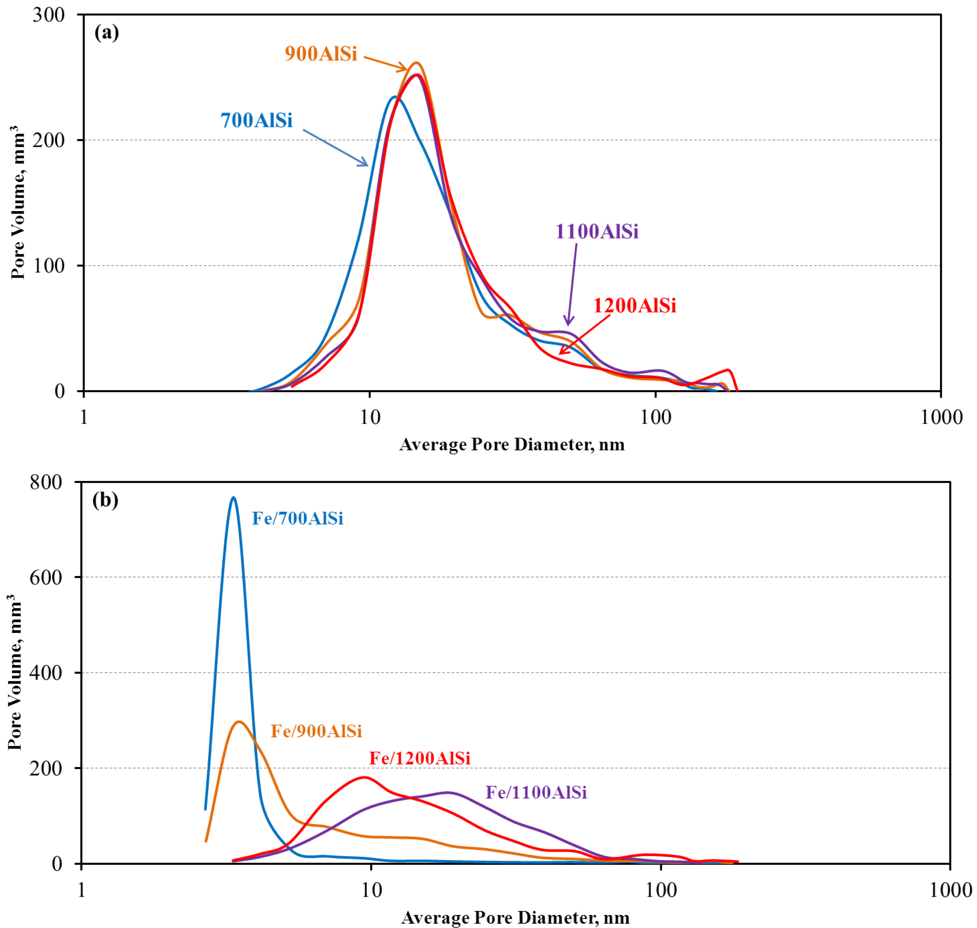
Support pretreatment temperature affects both the support and final catalyst pore properties, i.e., surface area, pore volume and pore size distribution. It is well known that γ-alumina is a metastable transition phase. When calcined at elevated temperatures, γ-alumina loses surface area and pore volume due to sintering and finally undergoes phase transition into α-phase with a lower surface area and pore volume. This trend is also observed in the present study, i.e., 700AlSi and 900AlSi have large surface areas (more than 250 m2/g) and pore volumes (more than 1.5 cm3/g), while 1100AlSi and 1200AlSi show relatively low surface areas (<170 m2/g) and pore volumes (<1 cm3/g). However, it should be mentioned that even at high-temperature pretreatment of 1200 °C, the AlSi support is still in γ-alumina phase with desirable surface area and pore volume. From the pore property point of view, 700AlSi and 900AlSi should be able to accommodate more Fe and be more suitable as catalyst supports. However, a drastic reduction in surface area, pore volume and pore size is observed in the final catalysts of Fe/700AlSi and Fe/900AlSi when Fe is loaded, as reported in Table 1. Nucleation of FeO crystallites is favored on hydroxylated alumina surfaces [34]. Therefore, much lower pore volume (0.16–0.26 cm3/g) and pore diameter (5.6–10.7 nm) of Fe/700AlSi and Fe/900AlSi with higher hydroxyl group concentrations (Table 5) suggest pore blockage of the support due to the presence of large Fe and Fe3O4 particles (>30 nm calculated from XRD).
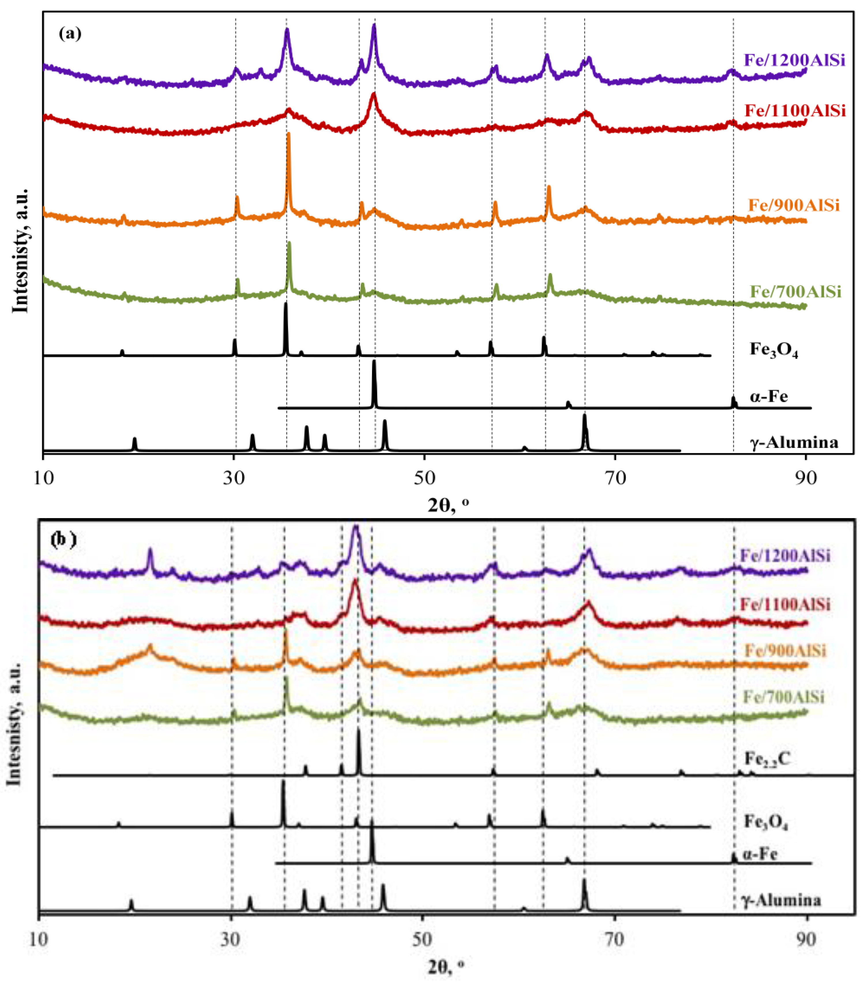
High-temperature dehydroxylation of Fe/1100AlSi and Fe/1200AlSi results in relatively uniform distribution of Fe2O3 and Fe3O4 crystallites inside the pores and, consequently, higher dispersion as evidenced by narrower iron carbide peaks observed in XRD. Although small by comparison, the pore volume and pore size of 1100AlSi and 1200AlSi are still remarkably large, especially when treated at such high temperatures to remove most of the hydroxyl groups. It should also be noted that the support pretreatment temperature up to 1100 °C improves the dispersion of iron particles as evidenced by decreasing iron particle sizes from ~40 nm to 4 nm (700–900 °C vs. 1100 °C support pretreatment temperature). However, higher support pretreatment temperatures (>1100 °C) further decreases the surface area and pore volume of the support, which consequently results in slightly lower dispersion and larger particle sizes (~8 nm). These results are in agreement with Qu et al. who found higher dispersion of Ag on silica as the calcination temperature increased to 700 °C, while lower dispersion resulted at higher calcination temperatures [24].

3.2. Effects of Support Pretreatment Temperature on Catalyst Chemical Properties

The results in this work provide correlations between support pretreatment temperature and the catalyst reducibility and extent of carbiding. Figure 8 shows the correlations between the support pretreatment temperature and hydroxyl groups (Table 5), and the extent of reduction from TPR (Table 3) and ε′-Fe2.2C from Mossbauer spectroscopy (Table 6). Higher dehydroxylation temperature of the support for Fe/1100AlSi and Fe/1200AlSi leads to highly reducible Fe2O3 and Fe3O
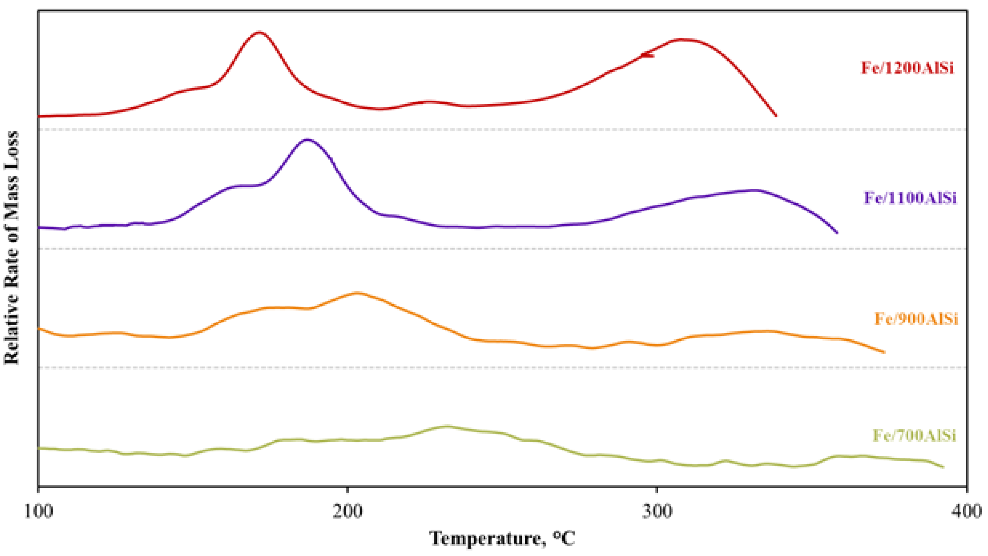
4, and subsequently a higher extent of reduction due to weaker FeO-support interactions. This observation is confirmed by H2-TPR and CO-TPR data shown in Figure 3 and Figure 4. Lower temperature and higher area of the reduction and carbiding peaks clearly support higher reducibility and carbiding extent as the calcination temperature of the support increases. This observation is further evidenced by a much lower Fe2+/Fe3+ percentage from iron aluminate spinel in Fe/1100AlSi and Fe/1200AlSi than that of Fe/700AlSi and Fe/900AlSi measured by Mossbauer spectroscopy. Brenner et al. reported that oxidation of Fe0 to Fe3+ occurs on the hydroxyl groups of alumina supports and a high density of FeO crystallites, which are difficult to reduce or carbide, are produced [35]. Therefore, highly reducible Fe2O3 and Fe3O4 clusters are formed in the near absence of surface OH groups. That likely explains why Fe/700AlSi and Fe/900AlSi with higher concentrations of surface hydroxyl groups have lower extents of reduction and a lower iron carbide phase.
Degree of carbidization can also be affected by iron particle size. Generally, larger iron oxide crystallites are easier to carbidize than smaller iron oxide counterparts [21]. However, this is only true if the surface chemistry of the support in supported iron catalyst would be relatively the same. For example, large iron particle sizes on Fe/700AlSi and Fe/900AlSi have the lowest degree of carbidization because of high metal oxide–support interaction at lower support dehydroxylation temperatures.

3.3. Effects of Support Pretreatment Temperature on Catalyst Performance

A positive correlation between the extent of reduction to Fe metal (from TPR data) following reduction in H2 and Fe carbide content is evident (Figure 8). This means that highly reducible Fe2O3 and Fe3O
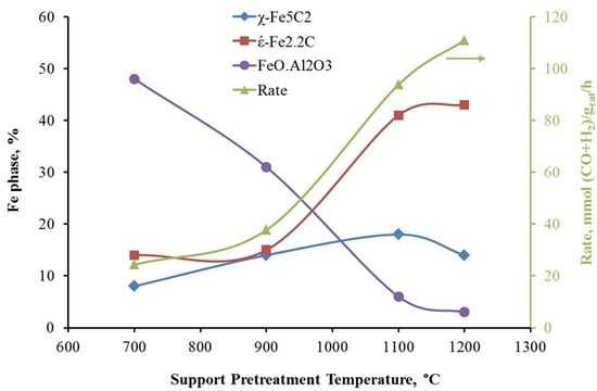
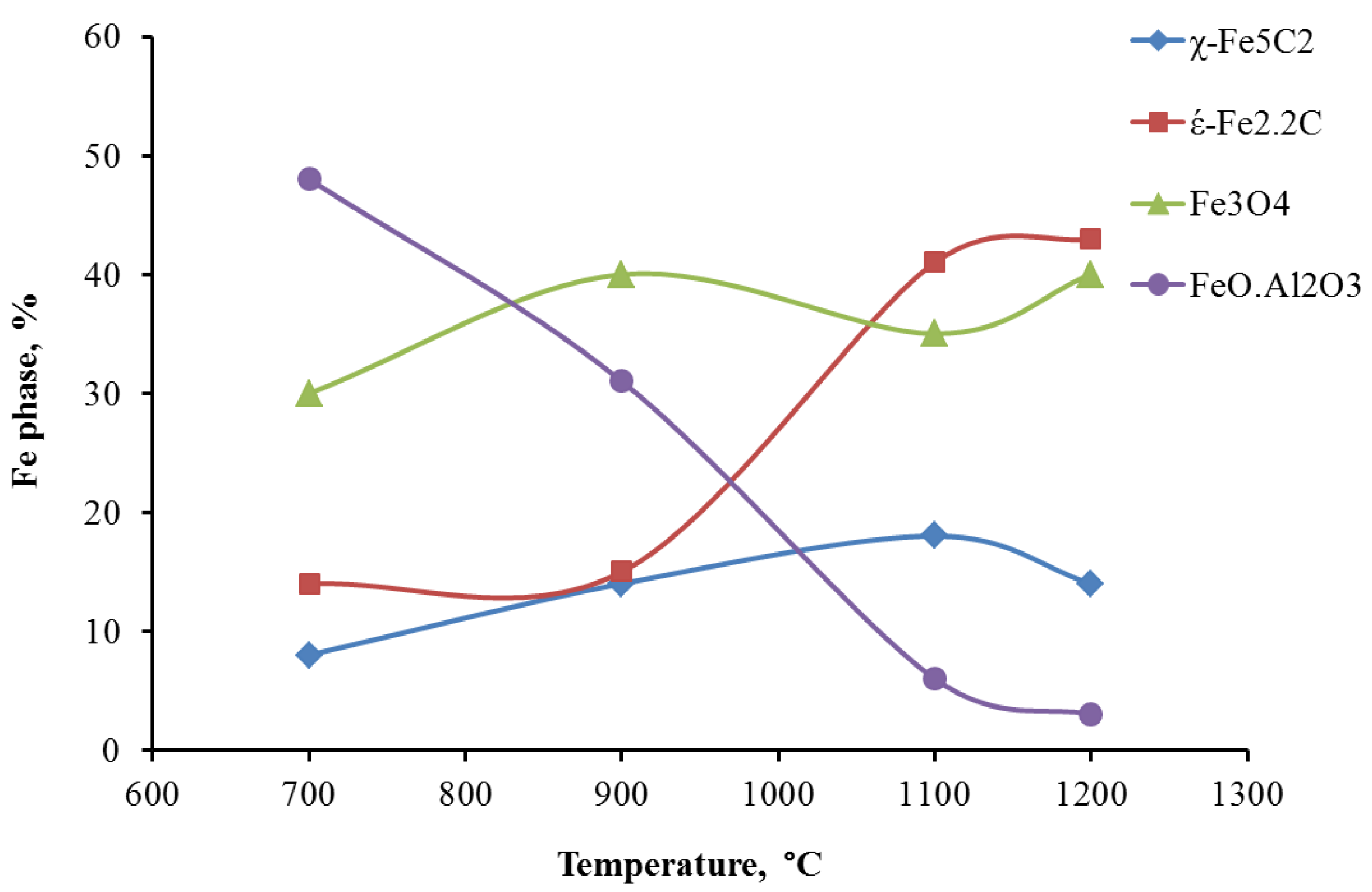
4 clusters result in a higher concentration of carbides, which are believed to be the active phase for FTS. The concentration of carbides increases significantly as the support pretreatment temperature increases, but it stays constant for pretreatment temperatures of 1100 °C and 1200 °C. This observation is consistent with syngas-TPR results, which show the carbiding of Fe/1100AlSi and Fe/1200AlSi is almost complete. In the present study, these iron carbide phases are identified as both ε′-Fe2.2C and χ-Fe2.5C by Mossbauer spectroscopy. The χ-Fe2.5C is only increased from 8% to 14–18% by higher pretreatment temperature of the support while the formation of ε′-Fe2.2C is significantly enhanced. In addition, the catalyst activity is also increased five-fold as the support pretreatment temperature increased from 700 °C to 1200 °C. The positive correlation between catalyst activity and ε′-Fe2.2C content is shown in Figure 9.
It has been reported that the formation of χ-Fe2.5C is favored over unsupported Fe catalysts under typical FT conditions and identified as an active iron carbide phase [36,37]. Nevertheless, the catalysts used in most of those studies are unsupported, whereas the catalyst in the present study is supported with pretreated silica-stabilized alumina. In the study by de Smit et al. using chemical potentials calculated by statistical thermodynamics, ε′-Fe2.2C formation is more favored for small particle sizes with less diffusion resistance and in the presence of a support material [38]. One can expect higher dispersion of active sites using supports, especially highly dehydroxylated supports used in this study which lower the metal oxide-support interaction and produce highly reducible and well dispersed iron oxides. On the other hand, the formation of ε′-Fe2.2C is more favored at low temperatures followed by its conversion to χ-Fe2.5C at higher temperatures (>250 °C). In this study, the calcined Fe/AlSi catalysts were activated under syngas at 20 atm by increasing the temperature from 180 °C and holding every 10 °C up to 280 °C, while keeping conversion less than 60% in each step. The highly dispersed ε′-Fe2.2C particles formed at low temperatures might have been stabilized on the support and their conversion to χ-Fe2.5C was not completed at higher temperatures of the activation process. This finding is in accordance with Niemantsverdriet et al. who reported the formation of ε′-Fe2.2C over iron supported on TiO2/CaO after FT reaction at 240 °C [39]. Raupp et al. also observed ε′-Fe2.2C on Fe/SiO2 exposed to FTS at 250 °C for 6 h [40].
The activity of Fe/AlSi, in this study, is among the highest in the literature for both unsupported and supported iron catalysts, and the catalyst is stable over 800 h time on stream. In addition, the significant correlation of the catalyst activity with the amount of ε′-Fe2.2C clearly show that ε′-Fe2.2C on AlSi support can be as active as χ-Fe2.5C on unsupported Fe catalysts. Thus, historically ε′-Fe2.2C was not considered the active phase due to a lack of evidence on unsupported iron catalysts. This is an important finding because the supported iron catalysts reported in the literature prior to this study were usually much less active than unsupported iron catalysts due to their high metal oxide–support interaction, and thus careful characterization of supported catalysts is scarce in the literature.

4. Materials and Methods

4.1. Catalyst Preparation

A series of iron catalysts supported on BYU alumina supports (Brigham Young University, Provo, UT, USA) pretreated at different temperatures were investigated in this study. The alumina support was doped with 5% SiO2 to increase the thermal stability, as described previously [25]. The supports were sieved to 250–595 µm (30–60 mesh size) and calcined in air at 700 °C, 900 °C, 1100 °C or 1200 °C for 4 h prior to impregnation. The supports were named starting with their calcination temperature, e.g., the support calcined at 700 °C was named 700AlSi. All four catalysts were prepared by incipient wetness using an aqueous solution containing desired amounts of ferric nitrate, copper nitrate and potassium bicarbonate in four steps. In each step, 10 wt % Fe with the desired amount of Cu and K were dissolved in sufficient water for incipient wetness and mixed into the catalyst support. The catalysts were sat at room temperature for 4 h, dried in an oven at 80 °C for 16 h, and finally calcined for 16 h at 300 °C in air. Nominal compositions (on a relative mass basis) of reduced catalysts were 100Fe/7.5Cu/4K/150Al2O3 for an iron loading of 40%. The final catalysts were named Fe/xAlSi, where “x” was the calcination temperature. For example, Fe/700AlSi was the Fe/Cu/K catalyst supported on the support calcined at 700 °C.
The samples were reduced at 280–320 °C in 10% H2/He for 10 h followed by 100% H2 for 6 h for characterization of reduced catalysts. Reduced catalysts were carefully passivated by first exposing each to flowing air in He (<1%) at room temperature followed by gradually increasing concentrations of air in helium while monitoring the temperature of the catalyst bed. The passivated reduced catalysts were carbided at 280 °C, 20 atm, and H2/CO = 1 for 24 h for characterization of carbided samples.

4.2. Catalyst Characterization

4.2.1. Nitrogen Adsorption/Desorption

Surface area, pore volume, and pore size distribution were calculated by nitrogen adsorption/desorption isotherms measured using a Micromeritics TriStar 3000 instrument (Norcross, GA, USA). The samples (0.3 g) were degassed at 120 °C for 12 h before measurement. Surface area was calculated by the BET model using P/P0 ranging from 0.05 to 0.2. Pore volume was measured by the single point method using P/P0 = 0.990. Pore size distribution was calculated using the desorption branch of the isotherm according to a newly developed slit pore-geometry model [41].

4.2.2. XRD

To determine the presence of different iron phases, X-ray diffraction patterns were collected for all the catalysts using a PANalytical X’Pert Pro diffractometer (Almelo, The Netherlands) with a Cu source and a Ge monochromator tuned to the Cu-K α 1 wavelength ( λ = 1.54 Å). Samples (reduced and passivated) were scanned from 10–90° using a step size of 0.016° and a step time of 350 s. Diffraction patterns were compared to standard patterns in the database.

4.2.3. TPR

TPR experiments were performed in a Mettler Toledo TGA/DSC 1 equipped with an automated GC 200 gas controller (Columbus, OH, USA) to understand the reduction/carbiding behavior of the catalysts. 10–20 mg of calcined samples were exposed to a reducing gas mixture of 10% H2/He (H2-TPR) or 10% syngas (H2:CO = 1) in He (syngas-TPR), while the temperature was increased at 3 °C/min from ambient to 700 °C.

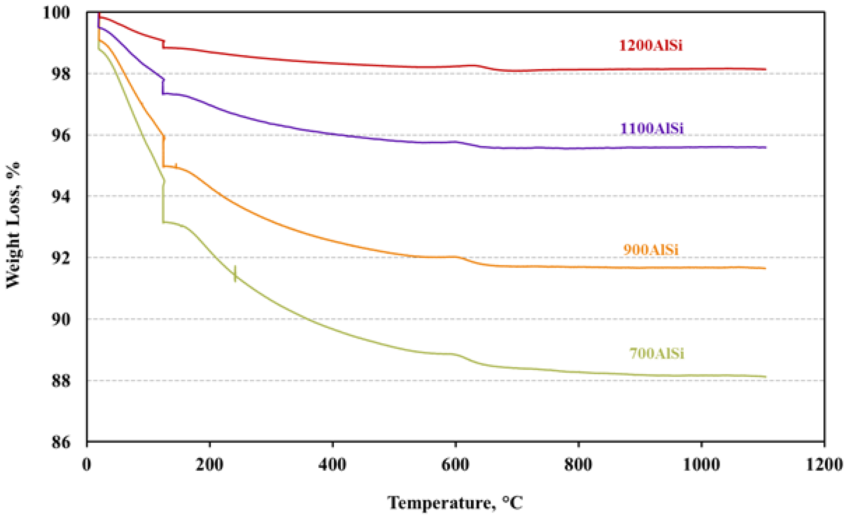
4.2.4. Hydroxyl Group Content Measurement

TGA was performed for alumina samples in the same TGA equipment (Columbus, OH, USA) described in Section 2.2.3 to determine hydroxyl group content. Pre-calcined alumina samples were heated at a rate of 5 °C/min from room temperature to 1100 °C in He flow of 80 mL/min and held for 2 h. The weight loss between 130 °C and 1100 °C was used to determine the hydroxyl group content.

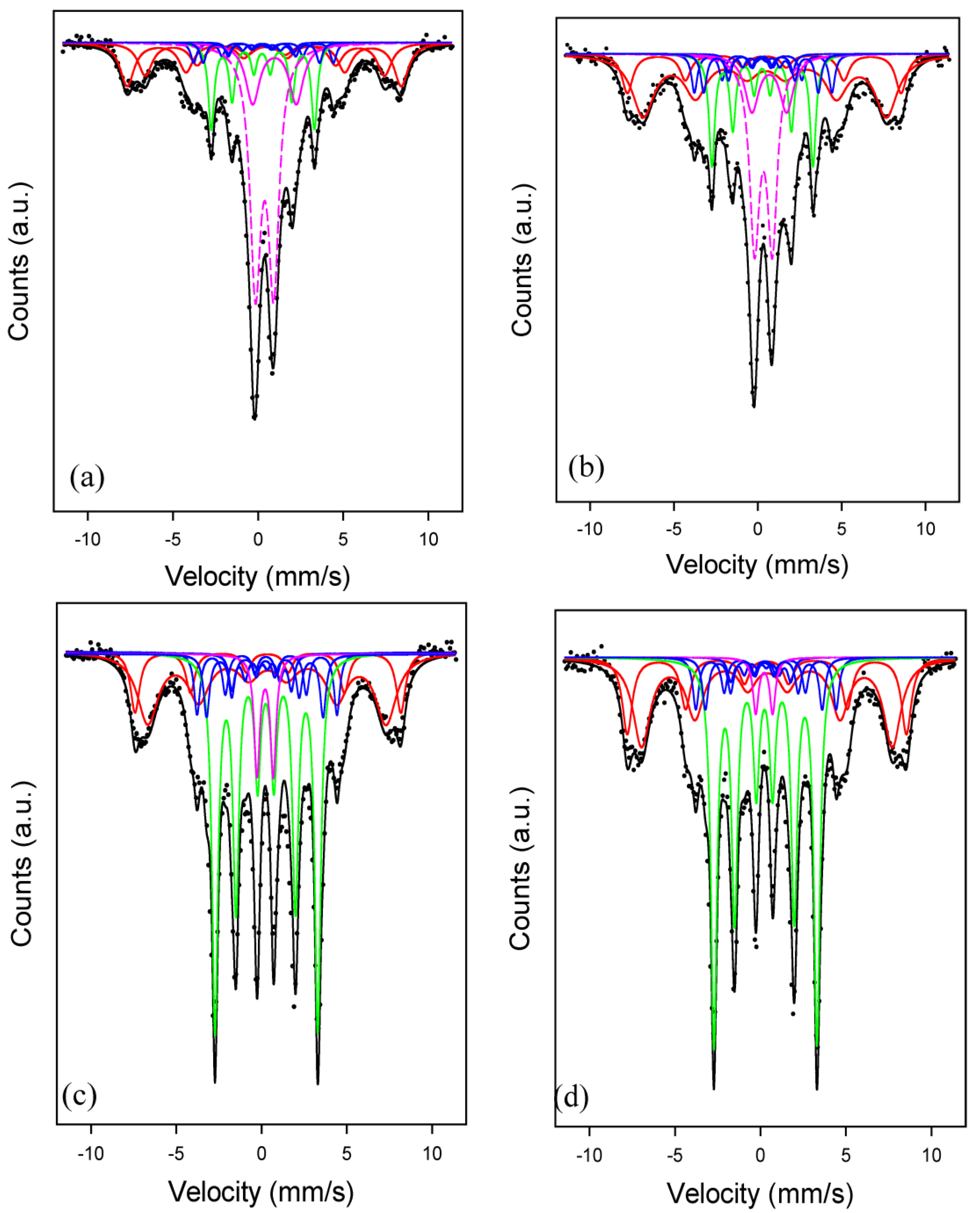
4.2.5. Mossbauer Spectroscopy

Mossbauer measurements were taken in transmission mode, with a 57Co source in Rh matrix mounted in a standard constant acceleration drive unit. Samples were placed inside a closed-cycle refrigerator for low-temperature measurements. All measurements were calibrated with respect to alpha-Fe. Analysis of measured spectra was carried out by using defined functions within the PeakFit program (version 4.12) using the least-squares-fitting routine. The parameters for each sub-spectrum in the fit consisted of the position, width and height of the first peak, the hyperfine magnetic field and the quadrupole electric field. Initially, the hyperfine magnetic fields of known FexC (2.2 ≤ x ≤ 3) were constrained but all other parameters could vary freely. Subsequently, the carbides’ hyperfine magnetic fields for the intense-distinct peaks could vary to obtain the best fit to the experimental data. The percentages of Fe in the different phases were determined from the areas under the peaks of the different sub-spectra. Calculated carbide sub-spectra of Fe percentages less than the experimental error of about ± 3% were then removed from the fitting procedure and data was fitted for the final results.

4.3. FTS Performance Measurement

FTS was conducted in a fixed-bed reactor (stainless steel, 3/8 inch OD) described previously [34]. Each sample (0.25 g, 250–590 μm) was diluted with 1 g silicon carbide to improve heat distribution in the catalytic zone.
Before FTS, the samples were reduced in situ at 280–320 °C in 10% H2/He for 10 h followed by 100% H2 for 6 h. After cooling to 180 °C, the system was then pressurized to 20 atm in syngas (H2:CO = 1), and the catalysts were activated by ramping and holding every 10 °C up to 280 °C, while keeping conversion less than 60% in each step. Activity and stability data were then obtained over the next 200–700 h as reaction temperatures were varied from 220 °C to 260 °C.
After leaving the reactor, the exit gas and liquid effluent passed through a hot trap (90 °C) and a cold trap (0 °C) to collect heavy hydrocarbons and liquid products. The effluent gaseous product was analyzed using an HP5890 gas chromatograph (Santa Clara, CA, USA) equipped with a thermal conductivity detector and 60/80 carboxene-1000 column. CO conversion and selectivities were determined with the use of an internal standard (Ar).

5. Conclusions

In summary, the results of this work demonstrate that support pretreatment temperature has a significant impact on the properties (physical and chemical) and catalytic performance of silica-stabilized alumina (AlSi) supported iron FTS catalysts. The high thermal stability of the AlSi support prepared in this study compared with the traditional alumina supports enabled us to study the effect of support pretreatment temperature at much higher temperatures than traditional practice (500–800 °C). Pretreating AlSi material at higher temperatures (i.e., 1100–1200 °C) before catalyst loading significantly removes support surface hydroxyl groups and reduces the iron oxide–support interaction. Therefore, the Fe/AlSi catalyst where the support calcined at 1100–1200 °C is (1) more reduced and more easily reduced, (2) more effectively carbided, and (3) significantly more active and productive. In addition, the results of this work show an excellent correlation of the catalyst activity and ε′-Fe2.2C content, which provide new insights into the active phase for supported FTS catalysts.

Acknowledgments

We thank Stacey Smith for her assistance in powder X-ray diffraction data analysis. This work is supported by members of the Brigham Young University Fischer–Tropsch Consortium and the University of Wyoming Clean Coal Technologies program.

Author Contributions

K.K. designed and performed the experiments and contributed to the writing of the manuscript; B.H. and T.O. performed catalyst characterizations, analyzed data, and wrote the paper; H.H. performed and analyzed Mossbauer spectroscopy tests; W.C.H. directed the research and contributed to the writing of the manuscript.

Conflicts of Interest

The authors declare no conflict of interest.

References

  1. Botes, F.G.; Niemantsverdriet, J.W.; van de Loosdrecht, J. A comparison of cobalt and iron based slurry phase fischer–tropsch synthesis. Catal. Today 2013, 215, 112–120. [Google Scholar] [CrossRef]
  2. Xu, J.; Yang, Y.; Li, Y.-W. Fischer–tropsch synthesis process development: Steps from fundamentals to industrial practices. Curr. Opin. Chem. Eng. 2013, 2, 354–362. [Google Scholar] [CrossRef]
  3. Bukur, D.B.; Lang, X.; Mukesh, D.; Zimmerman, W.H.; Rosynek, M.P.; Li, C. Binder/support effects on the activity and selectivity of iron catalysts in the fischer-tropsch synthesis. Ind. Eng. Chem. Res. 1990, 29, 1588–1599. [Google Scholar] [CrossRef]
  4. Bukur, D.B.; Sivaraj, C. Supported iron catalysts for slurry phase fischer–tropsch synthesis. Appl. Catal. A Gen. 2002, 231, 201–214. [Google Scholar] [CrossRef]
  5. O’Brien, R.J.; Xu, L.; Bao, S.; Raje, A.; Davis, B.H. Activity, selectivity and attrition characteristics of supported iron fischer–tropsch catalysts. Appl. Catal. A Gen. 2000, 196, 173–178. [Google Scholar] [CrossRef]
  6. Xu, J.; Bartholomew, C.H.; Sudweeks, J.; Eggett, D.L. Design, synthesis, and catalytic properties of silica-supported, pt-promoted iron fischer–tropsch catalysts. Top. Catal. 2003, 26, 55–71. [Google Scholar] [CrossRef]
  7. Li, S.; Li, A.; Krishnamoorthy, S.; Iglesia, E. Effects of Zn, Cu, and K promoters on the structure and on the reduction, carburization, and catalytic behavior of iron-based fischer–tropsch synthesis catalysts. Catal. Lett. 2001, 77, 197–205. [Google Scholar] [CrossRef]
  8. Chernavskii, P.A.; Kazak, V.O.; Pankina, G.V.; Perfiliev, Y.D.; Li, T.; Virginie, M.; Khodakov, A.Y. Influence of copper and potassium on the structure and carbidisation of supported iron catalysts for fischer-tropsch synthesis. Catal. Sci. Technol. 2017, 7, 2325–2334. [Google Scholar] [CrossRef]
  9. Li, T.; Virginie, M.; Khodakov, A.Y. Effect of potassium promotion on the structure and performance of alumina supported carburized molybdenum catalysts for fischer-tropsch synthesis. Appl. Catal. A Gen. 2017, 542, 154–162. [Google Scholar] [CrossRef]
  10. Ma, W.; Kugler, E.L.; Dadyburjor, D.B. Promotional effect of copper on activity and selectivity to hydrocarbons and oxygenates for fischer−tropsch synthesis over potassium-promoted iron catalysts supported on activated carbon. Energy Fuels 2011, 25, 1931–1938. [Google Scholar] [CrossRef]
  11. Wan, H.; Wu, B.; Xiang, H.; Li, Y. Fischer-tropsch synthesis: Influence of support incorporation manner on metal dispersion, metal-support interaction, and activities of iron catalysts. ACS Catal. 2012, 2, 1877–1883. [Google Scholar] [CrossRef]
  12. Pansanga, K.; Lohitharn, N.; Chien, A.C.Y.; Lotero, E.; Panpranot, J.; Praserthdam, P.; Goodwin, J.G. Copper-modified alumina as a support for iron fischer-tropsch synthesis catalysts. Appl. Catal. A Gen. 2007, 332, 130–137. [Google Scholar] [CrossRef]
  13. Kang, S.-H.; Bae, J.W.; Sai Prasad, P.S.; Jun, K.-W. Fischer–tropsch synthesis using zeolite-supported iron catalysts for the production of light hydrocarbons. Catal. Lett. 2008, 125, 264–270. [Google Scholar] [CrossRef]
  14. Suo, H.; Wang, S.; Zhang, C.; Xu, J.; Wu, B.; Yang, Y.; Xiang, H.; Li, Y.-W. Chemical and structural effects of silica in iron-based fischer–tropsch synthesis catalysts. J. Catal. 2012, 286, 111–123. [Google Scholar] [CrossRef]
  15. Malek Abbaslou, R.M.; Soltan, J.; Dalai, A.K. Iron catalyst supported on carbon nanotubes for fischer-tropsch synthesis: Effects of mo promotion. Fuel 2011, 90, 1139–1144. [Google Scholar] [CrossRef]
  16. Ma, W.; Ding, Y.; Yang, J.; Liu, X.; Lin, L. Study of activated carbon supported iron catalysts for the fischer-tropsch synthesis. React. Kinet. Catal. Lett. 2005, 84, 11–19. [Google Scholar] [CrossRef]
  17. Torres Galvis, H.M.; Bitter, J.H.; Davidian, T.; Ruitenbeek, M.; Dugulan, A.I.; de Jong, K.P. Iron particle size effects for direct production of lower olefins from synthesis gas. J. Am. Chem. Soc. 2012, 134, 16207–16215. [Google Scholar] [CrossRef] [PubMed]
  18. Cheng, K.; Ordomsky, V.V.; Virginie, M.; Legras, B.; Chernavskii, P.A.; Kazak, V.O.; Cordier, C.; Paul, S.; Wang, Y.; Khodakov, A.Y. Support effects in high temperature fischer-tropsch synthesis on iron catalysts. Appl. Catal. A Gen. 2014, 488, 66–77. [Google Scholar] [CrossRef]
  19. Chen, Q.; Liu, G.; Ding, S.; Chanmiya Sheikh, M.; Long, D.; Yoneyama, Y.; Tsubaki, N. Design of ultra-active iron-based fischer-tropsch synthesis catalysts over spherical mesoporous carbon with developed porosity. Chem. Eng. J. 2018, 334, 714–724. [Google Scholar] [CrossRef]
  20. Qin, H.; Wang, B.; Zhang, C.; Zhu, B.; Zhou, Y.; Zhou, Q. Lignin based synthesis of graphitic carbon-encapsulated iron nanoparticles as effective catalyst for forming lower olefins via fischer-tropsch synthesis. Catal. Commun. 2017, 96, 28–31. [Google Scholar] [CrossRef]
  21. Cheng, K.; Virginie, M.; Ordomsky, V.V.; Cordier, C.; Chernavskii, P.A.; Ivantsov, M.I.; Paul, S.; Wang, Y.; Khodakov, A.Y. Pore size effects in high-temperature fischer–tropsch synthesis over supported iron catalysts. J. Catal. 2015, 328, 139–150. [Google Scholar] [CrossRef]
  22. Xie, J.; Torres Galvis, H.M.; Koeken, A.C.J.; Kirilin, A.; Dugulan, A.I.; Ruitenbeek, M.; de Jong, K.P. Size and promoter effects on stability of carbon-nanofiber-supported iron-based fischer–tropsch catalysts. ACS Catal. 2016, 6, 4017–4024. [Google Scholar] [CrossRef] [PubMed]
  23. Kang, J.; Zhang, S.; Zhang, Q.; Wang, Y. Ruthenium nanoparticles supported on carbon nanotubes as efficient catalysts for selective conversion of synthesis gas to diesel fuel. Angew. Chem. 2009, 121, 2603–2606. [Google Scholar] [CrossRef]
  24. Qu, Z.; Huang, W.; Zhou, S.; Zheng, H.; Liu, X.; Cheng, M.; Bao, X. Enhancement of the catalytic performance of supported-metal catalysts by pretreatment of the support. J. Catal. 2005, 234, 33–36. [Google Scholar] [CrossRef]
  25. Mardkhe, M.K.; Huang, B.; Bartholomew, C.H.; Alam, T.M.; Woodfield, B.F. Synthesis and characterization of silica doped alumina catalyst support with superior thermal stability and unique pore properties. J. Porous Mater. 2016, 23, 475–487. [Google Scholar] [CrossRef]
  26. Mardkhe, M.K.; Keyvanloo, K.; Bartholomew, C.H.; Hecker, W.C.; Alam, T.M.; Woodfield, B.F. Acid site properties of thermally stable, silica-doped alumina as a function of silica/alumina ratio and calcination temperature. Appl. Catal. A Gen. 2014, 482, 16–23. [Google Scholar] [CrossRef]
  27. Keyvanloo, K.; Mardkhe, M.K.; Alam, T.M.; Bartholomew, C.H.; Woodfield, B.F.; Hecker, W.C. Supported iron fischer-tropsch catalyst: Superior activity and stability using a thermally stable silica-doped alumina support. ACS Catal. 2014, 4, 1071–1077. [Google Scholar] [CrossRef]
  28. Blanchard, J.; Abatzoglou, N.; Eslahpazir-Esfandabadi, R.; Gitzhofer, F. Fischer-tropsch synthesis in a slurry reactor using a nanoiron carbide catalyst produced by a plasma spray technique. Ind. Eng. Chem. Res. 2010, 49, 6948–6955. [Google Scholar] [CrossRef]
  29. Deng, C.-M.; Huo, C.-F.; Bao, L.-L.; Feng, G.; Li, Y.-W.; Wang, J.; Jiao, H. Co adsorption on Fe4c (100), (110), and (111) surfaces in fischer-tropsch synthesis. J. Phys. Chem. C 2008, 112, 19018–19029. [Google Scholar] [CrossRef]
  30. Ning, W.; Koizumi, N.; Chang, H.; Mochizuki, T.; Itoh, T.; Yamada, M. Phase transformation of unpromoted and promoted fe catalysts and the formation of carbonaceous compounds during fischer-tropsch synthesis reaction. Appl. Catal. A Gen. 2006, 312, 35–44. [Google Scholar] [CrossRef]
  31. Ordomsky, V.V.; Legras, B.; Cheng, K.; Paul, S.; Khodakov, A.Y. The role of carbon atoms of supported iron carbides in fischer-tropsch synthesis. Catal. Sci. Technol. 2015, 5, 1433–1437. [Google Scholar] [CrossRef]
  32. Zhao, S.; Liu, X.-W.; Huo, C.-F.; Li, Y.-W.; Wang, J.; Jiao, H. Surface morphology of haegg iron carbide (χ-Fe5c2) from ab initio atomistic thermodynamics. J. Catal. 2012, 294, 47–53. [Google Scholar] [CrossRef]
  33. Ek, S.; Root, A.; Peussa, M.; Niinisto, L. Determination of the hydroxyl group content in silica by thermogravimetry and a comparison with 1h mas nmr results. Thermochim. Acta 2001, 379, 201–212. [Google Scholar] [CrossRef]
  34. Keyvanloo, K.; Horton, J.B.; Hecker, W.C.; Argyle, M.D. Effects of preparation variables on an alumina-supported fecuk fischer-tropsch catalyst. Catal. Sci. Technol. 2014, 4, 4289–4300. [Google Scholar] [CrossRef]
  35. Brenner, A.; Hucul, D.A. Catalysts of supported iron derived from molecular complexes containing one, two, and three iron atoms. Inorg. Chem. 1979, 18, 2836–2840. [Google Scholar] [CrossRef]
  36. Pendyala, V.R.R.; Graham, U.M.; Jacobs, G.; Hamdeh, H.H.; Davis, B.H. Fischer-tropsch synthesis: Deactivation as a function of potassium promoter loading for precipitated iron catalyst. Catal. Lett. 2014, 144, 1704–1716. [Google Scholar] [CrossRef]
  37. Xu, J.; Bartholomew, C.H. Temperature-programmed hydrogenation (TPH) and in situ mössbauer spectroscopy studies of carbonaceous species on silica-supported iron fischer−tropsch catalysts. J. Phys. Chem. B 2005, 109, 2392–2403. [Google Scholar] [CrossRef] [PubMed]
  38. de Smit, E.; Cinquini, F.; Beale, A.M.; Safonova, O.V.; van Beek, W.; Sautet, P.; Weckhuysen, B.M. Stability and reactivity of ε-χ-θ iron carbide catalyst phases in fischer-tropsch synthesis: Controlling μc. J. Am. Chem. Soc. 2010, 132, 14928–14941. [Google Scholar] [CrossRef] [PubMed]
  39. Niemantsverdriet, J.W.; Van der Kraan, A.M.; Van Dijk, W.L.; Van der Baan, H.S. Behavior of metallic iron catalysts during fischer-tropsch synthesis studied with moessbauer spectroscopy, X-ray diffraction, carbon content determination, and reaction kinetic measurements. J. Phys. Chem. 1980, 84, 3363–3370. [Google Scholar] [CrossRef]
  40. Raupp, G.B.; Delgass, W.N. Moessbauer investigation of supported iron and iron-nickel (FeNi) catalysts. Ii. Carbides formed by fischer-tropsch synthesis. J. Catal. 1979, 58, 348–360. [Google Scholar] [CrossRef]
  41. Huang, B.; Bartholomew, C.H.; Woodfield, B.F. Improved calculations of pore size distribution for relatively large, irregular slit-shaped mesopore structure. Microporous Mesoporous Mater. 2014, 184, 112–121. [Google Scholar] [CrossRef]
Figure 1. Brunauer–Emmett–Teller (BET) results of (a) supports calcined at different temperatures and (b) catalysts with supports calcined at different temperatures.
Catalysts 08 00077 g001
Figure 2. X-ray diffraction (XRD) results for different support calcination temperatures of (a) reduced and (b) carbided catalysts. The catalysts reduced in H2 at 320 °C for 16 h and then passivated in 1% O2 in He. The passivated reduced catalysts were carbided at 280 °C in H2/CO = 1.
Catalysts 08 00077 g002
Figure 3. H2-TPR profiles of Fe catalysts supported on supports calcined at different temperatures.
Catalysts 08 00077 g003
Figure 4. Syngas-TPR for Fe catalysts with different support calcination temperatures focused on two stages of weight loss (inverted).
Catalysts 08 00077 g004
Figure 5. Thermogravimetric analysis (TGA) curves of supports calcined at different temperatures.
Catalysts 08 00077 g005
Figure 6. Mossbauer spectra of carbided (a) Fe/700AlSi, (b) Fe/900AlSi, (c) Fe/1100AlSi, and (d) Fe/1200AlSi. Spectra were recorded at 20 K. The passivated reduced catalysts were carbided at 280 °C in H2/CO = 1.
Catalysts 08 00077 g006
Figure 7. The change in distribution of the iron phases as the function of support pretreatment temperature.
Catalysts 08 00077 g007
Figure 8. Correlation between support treatment temperature and (a) hydroxyl groups, (b) extent of reduction, and (c) iron carbide phase.
Catalysts 08 00077 g008
Figure 9. Correlation of catalyst activity with iron carbide content.
Catalysts 08 00077 g009
Table 1. Surface area, pore volume and pore diameter of supports and catalysts after pretreatment for 2 h at four different temperatures.
Supports‘ Pretreatment Temperature, °CBrunauer–Emmett–Teller (BET) Surface Area, m2/gTotal Pore Volume, cm3/gAverage Pore Diameter, nm
SupportCatalystSupportCatalystSupportCatalyst
7003311801.750.1620.25.6
9002761641.530.2621.510.7
11001631170.990.5323.321.0
120076630.520.2523.520.6
Table 2. Crystallite size of reduced catalysts calculated from XRD.
CatalystParticle Size, nm
FeFe3O4
Fe/700AlSi38.933.0
Fe/900AlSi40.141.4
Fe/1100AlSi8.44.6
Fe/1200AlSi13.613.9
Table 3. Extent of reduction (EOR) from temperature programmed reduction (TPR) weight loss.
CatalystExtent of Reduction, %
First Stage aSecond StageThird StageTotal
Fe/700AlSi4.896.884.8516.6
Fe/900AlSi15.519.81.7837.1
Fe/1100AlSi22.231.31.1554.7
Fe/1200AlSi18.839.21.3859.4
a The first stage of weight loss consists of two peaks, the reduction of Fe2O3 to FeO and Fe3O4.
Table 4. Weight losses of Fe catalysts supported on AlSi calcined at different temperatures during reduction and carbiding stage.
CatalystExtent of Reduction/Carbiding a, %
First StageSecond StageTotal
Fe/700AlSi1.93.75.6
Fe/900AlSi12.85.418.2
Fe/1100AlSi18.57.526.0
Fe/1200AlSi15.310.425.7
a This was calculated based on the assumption of Fe2O3 to FeO for the first stage and FeO to Fe2.2C for the second stage.
Table 5. Concentrations of physisorbed water and OH groups for supports pretreated at different temperatures.
700AlSi900AlSi1100AlSi1200AlSi
First a mass loss, %6.85.02.61.2
Second b mass loss, %5.03.31.40.7
Physisorbed water, mmol/gAl2O33.72.71.40.6
OH group content, mmol/gAl2O35.63.71.60.8
a Weight loss up to 130 °C. b Weight loss between 130–1100 °C.
Table 6. Phase identification of iron from Mossbauer spectroscopy analysis at 20 K for reduced or carbided catalysts with support calcination at different temperatures.
CatalystIron Species, %
ReducedCarbided
Fe3O4FeFe2+ or Fe3+Fe3O4ε′-Fe2.2Cχ-Fe2.5CFe2+ or Fe3+
Fe/700AlSi637303014848
Fe/900AlSi6083240151431
Fe/1100AlSi6822103541186
Fe/1200AlSi682844043143
Table 7. Performance of four catalysts with different support temperatures in fixed bed reactor. T = 260 °C, H2/CO = 1, P = 20 bar.
CatalystRate, mmol (CO + H2)/gcat/hXCO a, %XCO + H2a, %Productivity, gHC/gcat/hCO2 Selectivity %H. C. Selectivity b, %
CH4C2C3+
Fe/700AlSi24.319.821.70.19634.113.311.275.5
Fe/900AlSi37.721.825.50.31631.513.38.9577.7
Fe/1100AlSi93.818.620.90.76333.014.18.9976.9
Fe/1200AlSi110.922.422.70.79640.914.09.7676.3
a XCO = CO conversion, XCO +H2 = CO and H2 conversion. b Hydrocarbon selectivity on a CO2-free basis.

