
Optimization of Enzyme-Mediated Calcite Precipitation as a Soil-Improvement Technique: The Effect of Aragonite and Gypsum on the Mechanical Properties of Treated Sand


Abstract
:1. Introduction
2. Materials and Methods
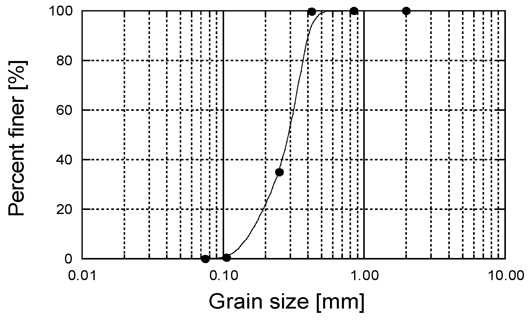
2.1. Materials
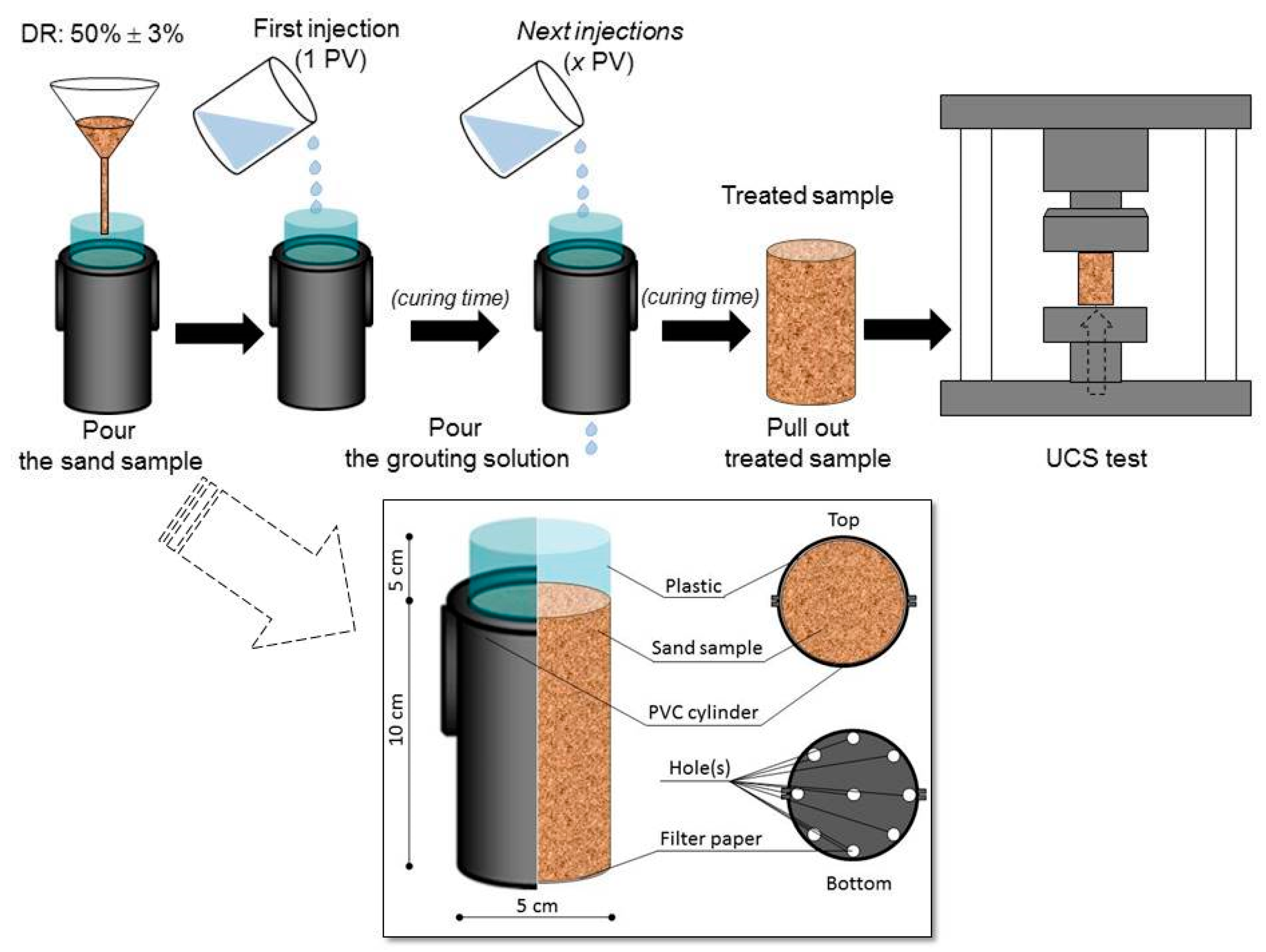
2.2. Precipitation Tests
- mp: mass of the precipitated materials evaluated from the tests (g)
- mt: theoretical mass of CaCO3 (g)
- C: concentration of the solution (mol/L)
- V: volume of the solution (L)
- M: molar mass of CaCO3 (100.087 g/mol)
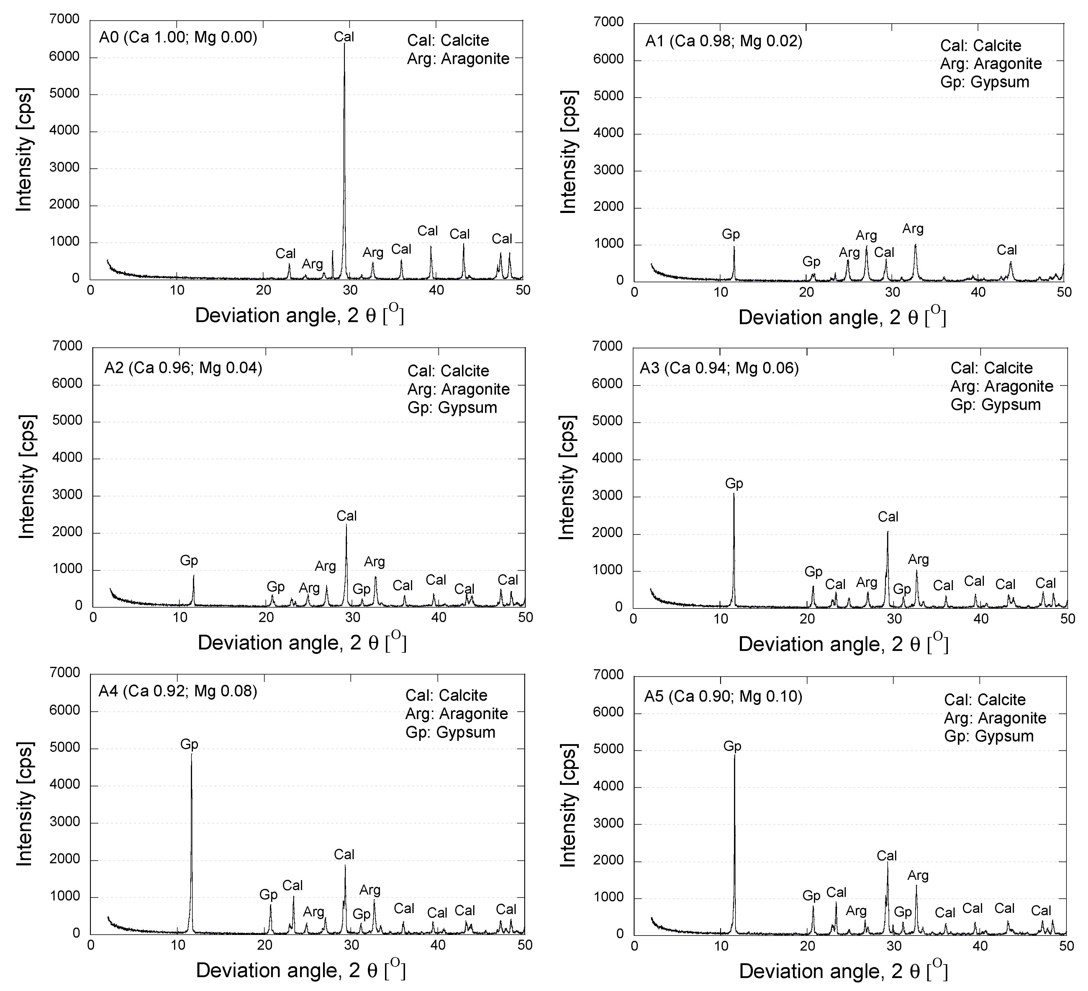
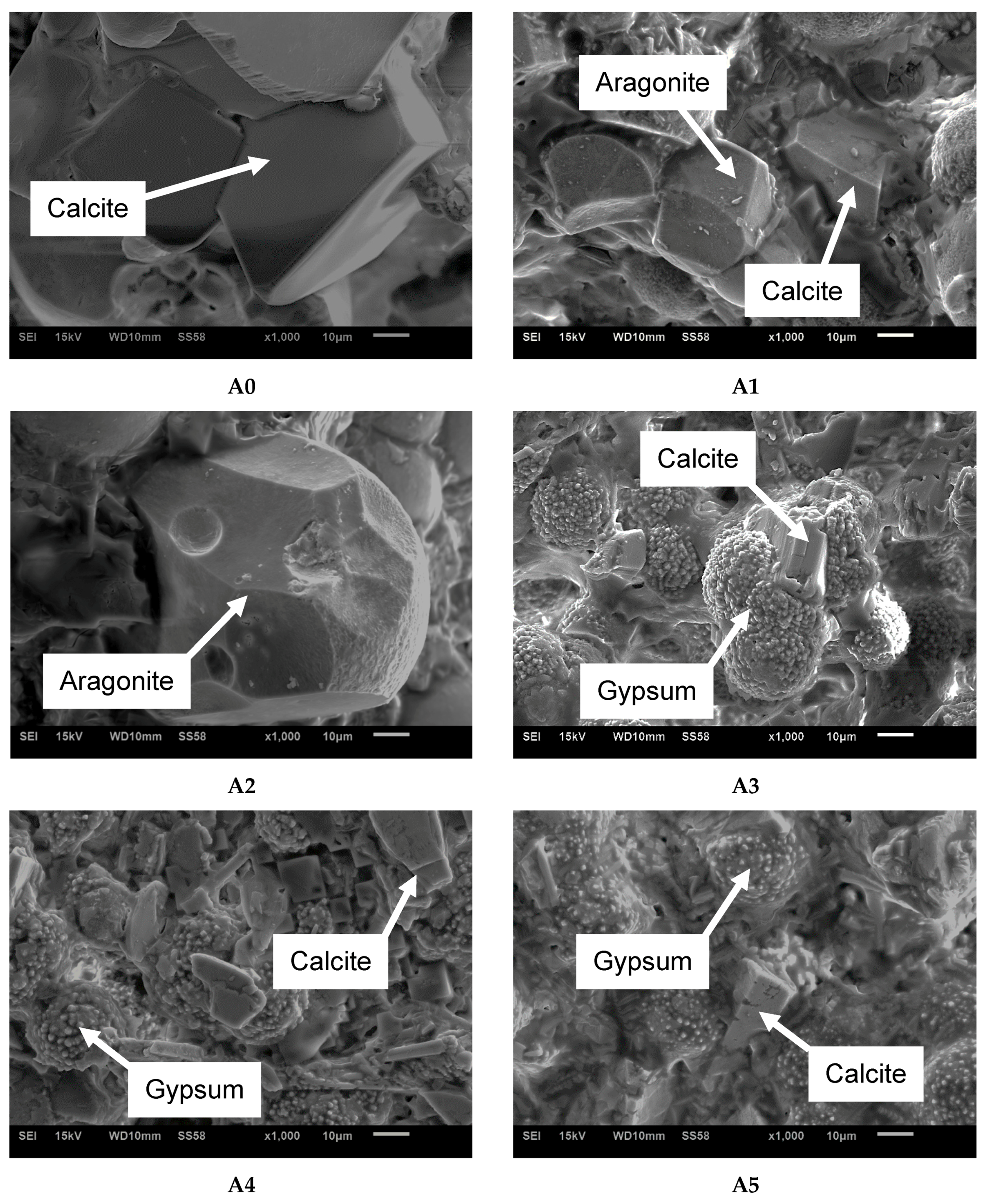
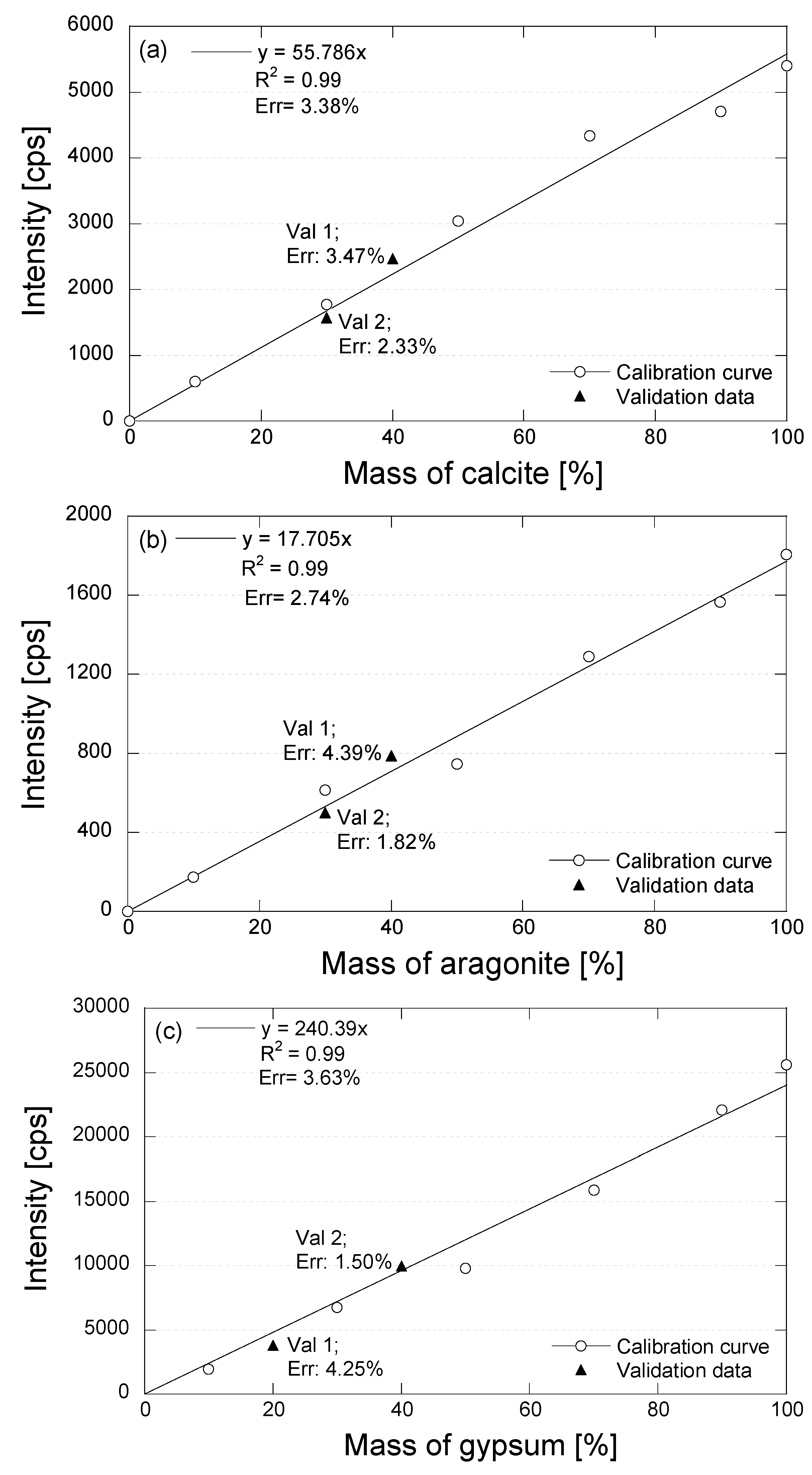
2.3. Mineralogical Analysis
2.4. Unconfined Compressive Strength Tests
3. Results and Discussion
4. Conclusions
Acknowledgments
Author Contributions
Conflicts of Interest
References
- Neupane, D.; Yasuhara, H.; Kinoshita, N. Evaluation of enzyme mediated calcite grouting as a possible soil improvement technique. In Computer Method and Recent Advances in Geomechanics; Oka, F., Murakami, A., Uzuoka, R., Kimoto, S., Eds.; CRC Press: Boca Raton, FL, USA, 2015; pp. 1169–1172. [Google Scholar]
- Neupane, D.; Yasuhara, H.; Kinoshita, N.; Putra, H. Distribution of grout material within 1-m sand column in insitu calcite precipitation technique. Soil Found. 2015, 55, 1512–1518. [Google Scholar] [CrossRef]
- Neupane, D.; Yasuhara, H.; Kinoshita, N.; Ando, Y. Distribution of mineralized carbonate and its quanti fi cation method in enzyme mediated calcite precipitation technique. Soil Found. 2015, 55, 447–457. [Google Scholar] [CrossRef]
- Putra, H.; Yasuhara, H.; Kinoshita, N.; Neupane, D.; Lu, C.-W. Effect of Magnesium as Substitute Material in Enzyme-Mediated Calcite Precipitation for Soil-Improvement Technique. Front. Bioeng. Biotechnol. 2016, 4, 37. [Google Scholar] [CrossRef] [PubMed]
- Van Paassen, L.A.; Daza, C.M.; Staal, M.; Sorokin, D.Y.; van der Zon, W.; van Loosdrecht, M.C.M. Potential soil reinforcement by biological denitrification. Ecol. Eng. 2010, 36, 168–175. [Google Scholar] [CrossRef]
- Cheng, L.; Cord-Ruwisch, R.; Shahin, M.A. Cementation of sand soil by microbially induced calcite precipitation at various degrees of saturation. Can. Geotech. J. 2013, 50, 81–90. [Google Scholar] [CrossRef]
- Whiffin, V.S.; van Paassen, L.A.; Harkes, M.P. Microbial Carbonate Precipitation as a Soil Improvement Technique. Geomicrobiol. J. 2007, 24, 417–423. [Google Scholar] [CrossRef]
- Harkes, M.P.; van Paassen, L.A.; Booster, J.L.; Whiffin, V.S.; van Loosdrecht, M.C.M. Fixation and distribution of bacterial activity in sand to induce carbonate precipitation for ground reinforcement. Ecol. Eng. 2010, 36, 112–117. [Google Scholar] [CrossRef]
- Yasuhara, H.; Neupane, D.; Hayashi, K.; Okamura, M. Experiments and predictions of physical properties of sand cemented by enzymatically-induced carbonate precipitation. Soil Found. 2012, 52, 539–549. [Google Scholar] [CrossRef]
- Putra, H.; Yasuhara, H.; Kinoshita, N.; Neupane, D. Optimization of Calcite Precipitation as a Soil Improvement Technique. In Proceedings of the 2nd Makassar International Conference on Civil Engineering, Makassar, Indonesia, 11–12 August 2015; pp. 9–14.
- Martinez, B.C.; DeJong, J.T.; Ginn, T.R.; Montoya, B.M.; Barkouki, T.H.; Hunt, C.; Tanyu, B.; Major, D. Experimental Optimization of Microbial-Induced Carbonate Precipitation for Soil Improvement. J. Geotech. Geoenviron. Eng. 2013, 139, 587–598. [Google Scholar] [CrossRef]
- DeJong, J.T.; Fritzges, M.B.; Nüsslein, K. Microbially Induced Cementation to Control Sand Response to Undrained Shear. J. Geotech. Geoenviron. Eng. 2006, 132, 1381–1392. [Google Scholar] [CrossRef]
- Neupane, D.; Yasuhara, H.; Kinoshita, N.; Unno, T. Applicability of Enzymatic Calcium Carbonate Precipitation as a Soil-Strengthening Technique. J. Geotech. Geoenviron. Eng. 2013, 139, 2201–2211. [Google Scholar] [CrossRef]
- Nemati, M.; Greene, E.A.; Voordouw, G. Permeability profile modification using bacterially formed calcium carbonate: Comparison with enzymic option. Process Biochem. 2005, 40, 925–933. [Google Scholar] [CrossRef]
- Yasuhara, H.; Hayashi, K.; Okamura, M. Evolution in Mechanical and Hydraulic Properties of Calcite-Cemented Sand Mediated by Biocatalyst. In Geo-Frontiers 2011: Advances in Geotechnical Engineering; ASCE: Reston, VA, USA, 2011; pp. 3984–3992. [Google Scholar]
- Van Paassen, L.A.; Ghose, R.; van der Linden, T.J.M.; van der Star, W.R.L.; van Loosdrecht, M.C.M. Quantifying Biomediated Ground Improvement by Ureolysis: Large-Scale Biogrout Experiment. J. Geotech. Geoenviron. Eng. 2010, 136, 1721–1728. [Google Scholar] [CrossRef]
- De Muynck, W.; de Belie, N.; Verstraete, W. Microbial carbonate precipitation in construction materials: A review. Ecol. Eng. 2010, 36, 118–136. [Google Scholar] [CrossRef]
- Okwadha, G.D.O.; Li, J. Optimum conditions for microbial carbonate precipitation. Chemosphere 2010, 81, 1143–1148. [Google Scholar] [CrossRef] [PubMed]
- Boyd, V.H. The Effect of Calcium and Magnesium on Carbonate Mineral Precipitation during Reactive Transport in a Model Subsurface Pore Structure. Ph.D. Thesis, University of Illinois, Champaign, IL, USA, 2012. [Google Scholar]
- Park, W.K.; Ko, S.-J.; Lee, S.W.; Cho, K.-H.; Ahn, J.-W.; Han, C. Effects of magnesium chloride and organic addictives on synthesis of aragonite precipitated calcium carbonate. J. Cryst. Growth 2008, 310, 2593–2601. [Google Scholar] [CrossRef]
- Litvin, A.L.; Valiyaveettil, S.; Kaplan, D.L.; Mann, S. Template-Directed Synthesis of Aragonite Under Supramolecular Hydrogen-Bonded Langmuir Monolayers. Adv. Mater. 1997, 9, 124–127. [Google Scholar] [CrossRef]
- “Aragonite.” A Dictionary of Earth Sciences. Encyclopedia.com. Available online: http://www.encyclopedia.com/science/dictionaries-thesauruses-pictures-and-press-releases/aragonite (accessed on 1 November 2016).
- “Calcite.” A Dictionary of Earth Sciences. Encyclopedia.com. Available online: http://www.encyclopedia.com/science/dictionaries-thesauruses-pictures-and-press-releases/calcite (accessed on 1 November 2016).
- Friedman, G.; Schultz, D. Precipitation of vaterite (CaCO3) during oil field drilling. Mineral. Mag. 1994, 58, 401–408. [Google Scholar] [CrossRef]
- Kahmi, S.R. On the structure of vaterite, CaCO3. Acta Crystallogr. 1963, 16, 770–772. [Google Scholar]
- Wang, J.; Becker, U. Structure and carbonate orientation of vaterite (CaCO3). Am. Mineral. 2009, 94, 380–386. [Google Scholar] [CrossRef]
- De Villiers, J.P.R. Crystal structures of aragonite, strontianite, and witherite. Am. Mineral. 1971, 56, 758–767. [Google Scholar]
- Dal Negro, A.; Ungaretti, L. Refinement of the Crystal Structure of Aragonite. Am. Mineral. 1971, 56, 768–772. [Google Scholar]
- ASTM International. International, Standard Practice for Classification of Soils for Engineering Purposes (Unified Soil Classification System); ASTM Standard Guide. D5521-5; ASTM: West Conshohocken, PA, USA, 2000. [Google Scholar]
- Yasuhara, H.; Neupane, D.; Kinosita, N.; Hayashi, K.; Unno, T. Solidification of sand soils induced by calcium carbonate precipitation utilizing biocatalyst. J. Jpn. Soc. Civ. Eng. Ser. C Geosph. Eng. 2014, 70, 290–300. [Google Scholar] [CrossRef]
- Chung, F.H. Quantitative interpretation of X-ray diffraction patterns of mixtures. III. Simultaneous determination of a set of reference intensities. J. Appl. Crystallogr. 1975, 8, 17–19. [Google Scholar] [CrossRef]
- Chipera, S.J.; Bish, D.L. Fitting Full X-Ray Diffraction Patterns for Quantitative Analysis: A Method for Readily Quantifying Crystalline and Disordered Phases. Adv. Mater. Phys. Chem. 2013, 3, 47–53. [Google Scholar] [CrossRef]
- Connolly, J.R. Introduction Quantitative X-ray Diffraction Methods. Fundamentals of X-ray Powder Diffraction; Nuevo Mexico University: Albuquerque, NM, USA, 2012. [Google Scholar]
- Demichelis, R.; Raiteri, P.; Gale, J.D.; Dovesi, R. The multiple structures of vaterite. Cryst. Growth Des. 2013, 13, 2247–2251. [Google Scholar] [CrossRef]


| Case | Conc. of Urea | Conc. of CaCl2 | Conc. of MgSO4 |
|---|---|---|---|
| (mol/L) | (mol/L) | (mol/L) | |
| A0 | 1.00 | 1.00 | 0.00 |
| A1 | 1.00 | 0.98 | 0.02 |
| A2 | 1.00 | 0.96 | 0.04 |
| A3 | 1.00 | 0.94 | 0.06 |
| A4 | 1.00 | 0.92 | 0.08 |
| A5 | 1.00 | 0.90 | 0.10 |
| Case | Material Mass (%) * | |||
|---|---|---|---|---|
| Pure Material | Internal Standard Material | |||
| Cal | Arg | Gp | SiO2 | |
| 1 | 0 | 0 | 0 | 100 |
| 2 | 10 | 10 | 10 | 90 |
| 3 | 30 | 30 | 30 | 70 |
| 4 | 50 | 50 | 50 | 50 |
| 5 | 70 | 70 | 70 | 30 |
| 6 | 90 | 90 | 90 | 10 |
| 7 | 100 | 100 | 100 | 0 |
| Val 1 | 40 | 40 | 20 | - |
| Val 2 | 30 | 30 | 40 | - |
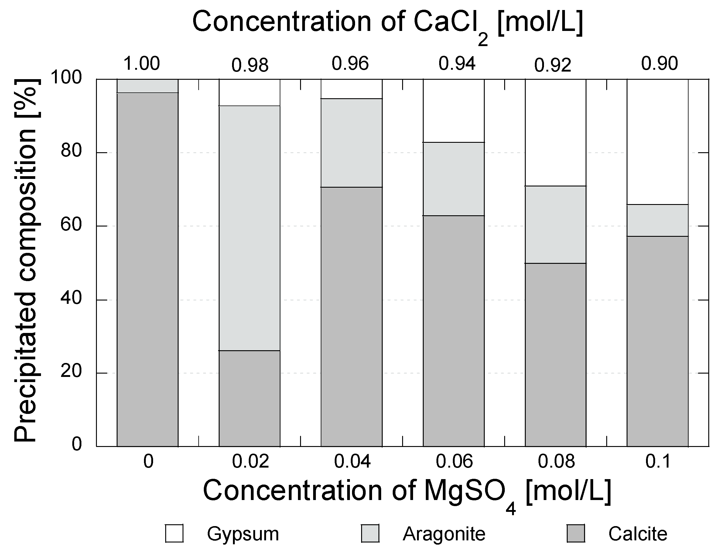
| Case | Concentration of CaCl2 (mol\L) | Concentration of MgSO4 (mol\L) | Total Precipitated Mass (g) * | Mineral Composition | |||||
|---|---|---|---|---|---|---|---|---|---|
| Calcite | Aragonite | Gypsum | |||||||
| (g) | (%) | (g) | (%) | (g) | (%) | ||||
| A0 | 1.00 | 0.00 | 1.71 | 1.65 | 96.67 | 0.06 | 3.33 | 0.00 | 0.00 |
| 1.72 | 1.65 | 96.13 | 0.07 | 3.87 | 0.00 | 0.00 | |||
| A1 | 0.98 | 0.02 | 1.82 | 0.48 | 26.58 | 1.19 | 65.30 | 0.15 | 8.12 |
| 1.79 | 0.46 | 25.72 | 1.22 | 68.21 | 0.11 | 6.07 | |||
| A2 | 0.96 | 0.04 | 1.98 | 1.39 | 70.38 | 0.48 | 24.46 | 0.10 | 5.14 |
| 1.98 | 1.41 | 71.00 | 0.47 | 23.64 | 0.11 | 5.32 | |||
| A3 | 0.94 | 0.06 | 2.33 | 1.41 | 60.36 | 0.46 | 19.72 | 0.46 | 19.67 |
| 2.25 | 1.47 | 65.30 | 0.45 | 20.15 | 0.33 | 14.55 | |||
| A4 | 0.92 | 0.08 | 2.55 | 1.31 | 51.29 | 0.49 | 19.21 | 0.75 | 29.50 |
| 2.60 | 1.26 | 48.61 | 0.59 | 22.64 | 0.75 | 28.75 | |||
| A5 | 0.90 | 0.10 | 3.28 | 1.91 | 58.13 | 0.30 | 9.19 | 1.07 | 32.68 |
| 3.51 | 1.99 | 56.57 | 0.28 | 8.08 | 1.25 | 35.35 | |||
| Case | Grouting Solution | Conc. of Urease (g/L) | Reagent Compositions | ||
|---|---|---|---|---|---|
| Conc. of Urea | Conc. of CaCl2 | Conc. of MgSO4 | |||
| (mol\L) | (mol\L) | (mol\L) | |||
| U1 | A0 | 2.00 | 1.00 | 1.00 | 0.00 |
| U2 | A1 | 2.00 | 1.00 | 0.98 | 0.02 |
| U3 | A2 | 2.00 | 1.00 | 0.96 | 0.04 |
| U4 | A5 | 2.00 | 1.00 | 0.90 | 0.10 |
© 2017 by the authors. Licensee MDPI, Basel, Switzerland. This article is an open access article distributed under the terms and conditions of the Creative Commons Attribution (CC BY) license ( http://creativecommons.org/licenses/by/4.0/).
Share and Cite
Putra, H.; Yasuhara, H.; Kinoshita, N.; Hirata, A. Optimization of Enzyme-Mediated Calcite Precipitation as a Soil-Improvement Technique: The Effect of Aragonite and Gypsum on the Mechanical Properties of Treated Sand. Crystals 2017, 7, 59. https://doi.org/10.3390/cryst7020059
Putra H, Yasuhara H, Kinoshita N, Hirata A. Optimization of Enzyme-Mediated Calcite Precipitation as a Soil-Improvement Technique: The Effect of Aragonite and Gypsum on the Mechanical Properties of Treated Sand. Crystals. 2017; 7(2):59. https://doi.org/10.3390/cryst7020059
Chicago/Turabian StylePutra, Heriansyah, Hideaki Yasuhara, Naoki Kinoshita, and Akira Hirata. 2017. "Optimization of Enzyme-Mediated Calcite Precipitation as a Soil-Improvement Technique: The Effect of Aragonite and Gypsum on the Mechanical Properties of Treated Sand" Crystals 7, no. 2: 59. https://doi.org/10.3390/cryst7020059