Article

Influence of the Heat Dissipation Mode of Long-Flute Cutting Tools on Temperature Distribution during HFCVD Diamond Films

1
Mechanical Institute of Technology, Wuxi Institute of Technology, Wuxi 214121, China
2
School of Engineering Science and Technology, Shanghai Ocean University, Shanghai 200240, China
3
Zhangjiagang Weina New Materials Technology Co., Ltd., Suzhou 201316, China
*
Authors to whom correspondence should be addressed.
Crystals 2019, 9(8), 394; https://doi.org/10.3390/cryst9080394
Submission received: 28 June 2019 / Revised: 24 July 2019 / Accepted: 29 July 2019 / Published: 30 July 2019
(This article belongs to the Special Issue Synthesis and Characterization of Diamond Crystals)

Abstract

:
The distribution of substrate temperature plays a decisive role on the uniformity of polycrystalline diamond films on cemented carbide tools with a long flute, prepared by a hot filament chemical vapor deposition (HFCVD). In this work, the heat dissipation mode at the bottom of tools is a focal point, and the finite volume method (FVM) is conducted to simulate and predict the temperature field of tools, with the various materials of the holder placed under the tools. The simulation results show that the thermal conductivity of the holder affects the temperature difference of the individual tools greatly, but only affects the temperature of different tools at the same XY plane slightly. Moreover, the ceramic holder can reduce the difference in temperature of an individual tool by 54%, compared to a copper one. Afterwards, the experiments of the deposition of diamond films is performed using the preferred ceramic holder. The diamond coatings on the different positions present a highly uniform distribution on their grain size, thickness, and quality.

1. Introduction

Chemical vapor deposition (CVD) allows diamond films to deposit directly and conveniently on different shapes of substrates, making possible the use of the many excellent mechanical properties of diamond films in a wide field of industrial applications [1,2]. For example, the diamond film attached to the surface of cemented carbide (WC-Co) tools with a long-flute can be applied to the processing of hard-to-machine materials such as aluminum, aluminum–silicon alloy, graphite, zirconia ceramics and composite materials [3,4,5], which have been given increasing attention by both academy and industry.
Hot filament CVD (HFCVD) is one of the earliest and most mature methods for depositing the diamond films. Compared with other CVD methods, this method has such advantages as simple equipment, easy control of growth process, and being suitable for the high-throughput preparation of CVD diamond coated tools [6,7,8]. For the high-efficiency and high-quality fabrication of the diamond coated tools, especially for tools with a long flute, the uniformity of thickness, grain size, and purity of the CVD diamond coating, is one of the most vital indexes. The serious non-uniform coatings may cause the fluctuation of cutting force and increase the vibration in the process of machining, thus directly affecting the service life of the tool and the machining quality of parts [9]. The homogeneous films depend mainly on the homogeneity of the deposition temperature of the tool substrate and the surrounding gas [10]. Some studies have been put into creating a numerical model of the filament-assisted diamond growth environment to calculate the gas-phase and substrate temperature distributions and optimize their uniformity through manipulating the filament arrangement [11,12]. Notably, however, most previous studies have neglected the effects of the thermal conduction and convection on the growth environment. In Ref. [13,14,15] we proposed a simulation method based on the finite volume method (FVM), coupling all means of heat transfer mechanisms (radiation, conduction, and convection) and adopting a three-dimensional model well in accordance with the actual reactive chamber, and also optimized the uniformity of the temperature field generated on the flat substrates by changing the filament arrangements. However, we found that it is limited to improving the uniformity of substrate temperature by changing the arrangement of filaments, especially when the substrate is the cutting tool with a long flute. As seen in Figure 1, as the flute is over 30 mm, the diamond coatings on the tools shows an extreme non-uniformity along the axis of tools, due to an obvious temperature gradient along the tool tip toward the tool shank. This is because the substrate and its surrounding temperature decay rapidly with the distance from the center temperature generated from the hot filaments, and the filaments are usually located near the tip of the tools.
In fact, other than the arrangement of the hot filaments near the tool tip, the temperature of the tools is also determined by the mode of the heat dissipation at the bottom of the long-flute tools. However, to our knowledge, few investigations have focused on the effect of the heat dissipation mode of the tools on the substrate temperature. In the present work, we also adopt the FVM, coupling all means of the heat transfer mechanisms, to simulate and predict the temperature distribution of milling tools using the different heat dissipation modes at the bottom of the tools (i.e., various materials of the supporting platform). Moreover, the effect of thermal conductivity of platforms on the temperature difference of tools is also discussed. On this basis, a preferred material of platform is selected, with which an actual deposition experiment of diamond coated milling cutters is conducted to verity the correctness of simulation results.

2. Simulation Details and Results

2.1. Model and Simulation Method

In order to simplify the simulation, the following assumptions are made: (1) the working pressure in the reaction chamber is constant; (2) the simulated gas is considered only hydrogen, because the methane content in the actual deposition process (only 2~4%) is very low; (3) no chemical exothermic reaction occurs in the reaction chamber; (4) The miscellaneous curves of the flute of the milling cutter increase the difficulty of meshing surface and greatly increase the amount of calculation. Therefore, the simulated milling cutters are simplified to cylindrical bars with an equivalent size.
The computational model of HFCVD reactor is built using a three-dimensional CAD (Computer Aided Design) software, and the model and its coordinates are shown in Figure 2. A copper water-cooled worktable is 200 mm in length, 130 mm in width and 5 mm in wall thickness, which is to keep the substrate temperature as a constant in the HFCVD reactor [14]; the 25 milling cutters with the diameter of 10 mm that are taken as an example are placed on a support platform measuring 200 × 130 × 30 mm, and the material of the platform is the object of simulation optimization; 6 tantalum filaments, 150 mm long and 0.6 mm in diameter, are fixed on the top of the tools with the equal spacing; the reactive gas is introduced from a bottom inlet at the left side of the container and flows out from a bottom outlet at the right one. Then the model is meshed by a mesh generation software, GAMBIT. The details of mesh model are as follows: the number of cells, 2,813,600; faces, 5,808,856; nodes, 587,039. Then a reliable commercial software, FLUENT, based on the FVM, is adopted to simulate the temperature field of the HFCVD meshing model. The initial environmental temperature and pressure in the reactor are, respectively, defined as 25 °C and 3000 Pa. The detailed computational theories and simulation parameters have been described in the previous study [14]. The various materials properties of the holder and others are listed in Table 1. The computation time is about 10–24 hours.

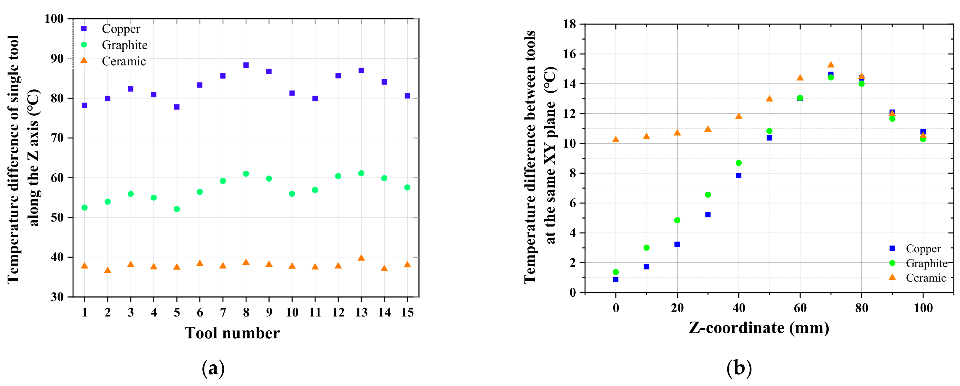
2.2. Simulation Results and Discussion

After the simulation calculation, the temperature distribution of milling cutters at the different locations on the copper, graphite and ceramics holders are investigated and compared. For the convenience of description, the 25 milling cutters are numbered as 1 to 25 from left to right and top to bottom, as shown in Figure 3a. Since the structure of the reaction chamber and the arrangement of milling cutters are completely symmetrical in the XZ plane (as shown in Figure 2), only numbers 1–15 of the milling cutters need to be analyzed in the following. Figure 3b–d represent the temperature profiles in 15 mills placed on the various holders and the curve graphs of temperature in the typical tools. For each case, the maximum temperature appears on the centered tool (No. 13), and the average temperature of a single tool decreases gradually from the centered tool toward the edge ones. For each tool, the substrate temperature always reduces rapidly with the distance from the hot filaments. Nevertheless, the different holders can result in the different fluctuation range of the temperature.
Figure 4a represents the values of difference between the maximum and minimum temperatures of No. 1–15 tool along the Z axis, respectively, while the black curve in Figure 5 represents their average value for each type of holder. When the thermal conductivity of copper, graphite, ceramic is 388, 151, 63 W/(m·k), the corresponding temperature difference of each tool ranges from 78 to 88 °C, from 52 to 61 °C, and from 37 to 40 °C and the average difference is 83, 57, and 38 °C, respectively. Obviously, the heat dissipation condition at the bottom of the tools plays a decisive role on the temperature distribution of the single tool along the Z direction. A lower thermal conductivity of tools’ holder as an intermediate insulation layer could reduce the impact of the temperature of the water-cooled worktable (close to the room temperature) on the overall temperature of the tools. Hence, the ceramic holder leads to the minimum average temperature difference of an individual mill. Moreover, compared with the traditional copper holder, the difference with the ceramic one decreases by 54 %. It should be noted that since the permitted substrate temperature should be generally maintained around 600–1000 °C for depositing the polycrystalline diamond films [8,12], too low a thermal conductivity may result in an excessively high substrate temperature that exceeds the permitted values. Fortunately, the substrate temperature is maintained in the permissible range for the three cases. Figure 4b shows the values of the temperature difference between the 15 tools at the same XY plane along the Z axis, while the blue curve in Figure 5 represents their average value for each type of holder. The three curves own a similar shape, implying that the temperature difference has a similar changing trend. For all of the curves, the maximum temperature difference of about 14 °C appears at Z = 70 mm, and almost the same values appear at the same position in the range of Z = 70–100 mm, being closer to the hot filaments. For Z from 0 to 70 mm, the smaller temperature difference is caused by the copper and graphite holders, rather than by the ceramic one. But as a whole, for either holder, comparing the two curves shown in Figure 5, the average temperature difference corresponding to the blue curve is obviously smaller than that corresponding to the black one. This suggests that a better uniformity in the temperature of tools can be obtained in the same XY plane, and that the heat dissipation mode at the bottom of the tools has a slight effect on the distribution of temperature in the XY plane. In fact, the temperature distribution of the substrate in the same XY plane is mainly decided by the arrangement of hot filaments [14]. Additionally, it should be mentioned that the errors between the simulated temperatures and actual ones in the deposition process are all less than 3~5 % [13,14], and thus can reasonably be ignored.
In a word, the ceramic holder with a low thermal conductivity can help to greatly enhance the uniformity of temperature on the single long-flute cutting tool, but has no effect on improving the uniformity of temperature between tools in the same deposited batch.

3. Deposition Experimental Details and Results

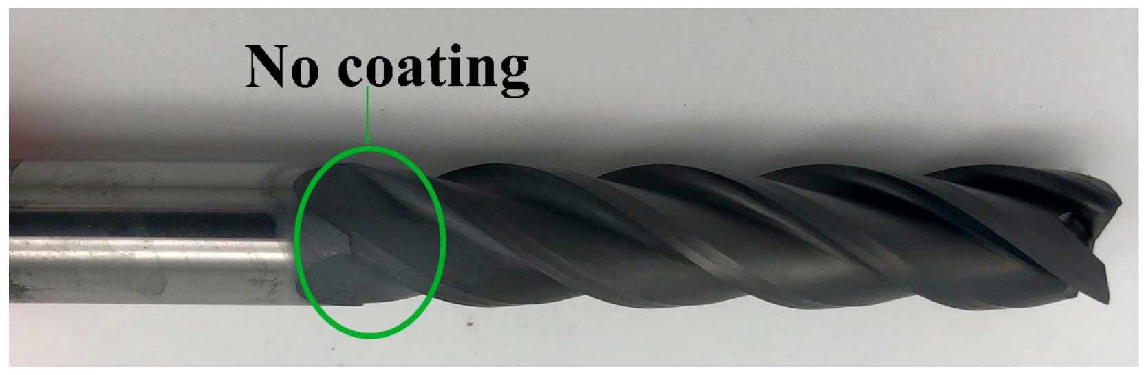
3.1. Experimental Details

The 25 WC-Co end mill tools with 4 flutes, 100 mm long, 50 mm long in the cutting edge, and 10 mm in nominal diameter, and 6% Co composition are used as the substrates. All the milling tools are treated by a two-step pretreatment, which are firstly etched with Murakami’s reagent for 20 min and then Caro’s acid solution for 30 s. Subsequently, they are submitted to an abrading process for 5 min for removing the loose layer and residual cobalt content on the surfaces of the tools by using walnut shell and diamond mixed particles [16]. After the grinding process, all the samples need to be cleaned in an ultra-sonic bath with deionized water and acetone for 5 min, in order to remove the mixed particles.
The pretreated tools are deposited in a self-made HFCVD reactor. The ceramic is selected as the supporting holder beneath the tools according to the simulation results, which may lead to the least difference in temperature for the single milling tool. The arrangement of hot filaments identifies with that which is in the simulation. Nucleation and growth conditions are summarized in Table 2. The surface morphologies and film thickness of the tools are observed by Field Emission Scanning Electron Microscopy (FE-SEM, ULTRA55, Zeiss, Oberkochen, Germany). The quality of the as-deposited samples is examined by Micro-Raman Spectroscopy (SPEX1403, Renishaw, Gloucestershire, England).

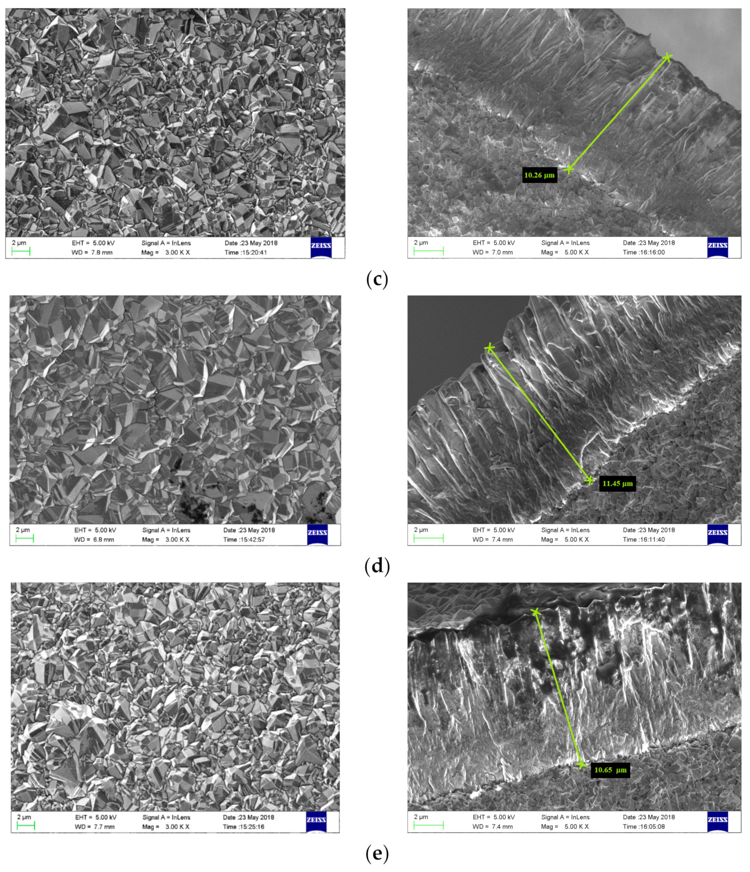
3.2. Characterization of As-Fabricated Diamond Films

Figure 6a shows a representative diamond coated tool fabricated based on the ceramic holder. From the head to tail of the cutting edge, the substrate is covered with the complete diamond films. Apparently, the uniformity of diamond coatings for the ceramic is significantly better than that for the copper shown in Figure 1. Furthermore, in the two cases, the deposition and filaments parameters are the same. This result verifies the correctness of the simulation results and the ceramic holder can contribute to improving the uniformity of coatings on the long-flute cutting tool. In addition, the graphite also leads to a smaller temperature gradient on the tools according to the simulation results, but the hardness of graphite is too low to be suitable for fixing the position of the cemented carbide tools.
In order to compare the uniformity of coatings on the mills located in the different position based on the ceramic holder, two representative ones, the No. 13 in the middle and the No. 1 in the edge position, are selected. For each as-selected tool, the two-representative positions, the head and tail of the cutting edge, named A and B, respectively, are characterized. Figure 6b–e shows the FESEM image of the surface morphology of the diamond coated tools at the various positions. All the samples present the compact and continuous polycrystalline films and well-developed crystals, with a grain size around 2–5 μm. To observe the uniformity of diamond film thickness, the two tools are truncated at A and B respectively. The film thickness of No. 13 mills at the A position is 11.45 μm and that at B is 10.85 μm. The thickness of No. 1 mills at the A position is 11.67 μm and that at B is 10.26 μm. The thickness fluctuations are relatively small from 0.5 to 1.5 μm. It should be mentioned that the difference in the grain size and thickness of films at the same position among the various tools is smaller than that at the different positions on the same milling tool. This is attributed to the temperature difference in the former case being smaller than that of the latter case. What is more, the hot filament is the energy source for the decomposition of mixed gases. Increasing the distance from the hot filament to the deposited, the active species concentration clearly decays [17,18]. Hence, the growth rate of the diamond at B is lower than that of A, and the homogeneity of the grain size at B is not as good as that which is at A. However, in the face milling process, the tail of the cutting edge generally plays the role of removing chips and is not involved in the cutting process. Hence, the slight non-uniform coatings on the tail has a neglected effect on the tool life and machining quality.
As-prepared CVD diamond films are characterized by Raman spectroscopy. Figure 7 is the corresponding Raman spectra. The characteristic peaks of diamond around 1336 cm−1 are very sharp, and the diamond-like peaks at 1580 cm−1 are very low. These prove that the diamond films present the high purity and the obvious compressive residual stress around −2.3 GPa at any position. It should be noted that the diamond films are under compressive stress, which is better than tensile stress for the films’ adhesion. The stress is calculated according to the following equation [19]:
σ = −0.567(vmv0) (Gpa)
where vm and v0 are the Raman peak positions of stressed and natural diamond (1332 cm−1), respectively.

4. Conclusions

In the high-throughput depositing process of diamond films on cemented carbide (WC-Co) long-flute tools, the tools’ working temperature plays a decisive role on the uniformity of diamond coatings. The heat dissipation mode at the bottom of the tools is one of the most important factors to affect the distribution of the temperature on the tools. Finite volume method (FVM) is performed to simulate the temperature field of tools with the various materials of the holder acting as an interlayer between the tools and water-cooled worktable. From the simulation results, the thermal conductivity of the holder influences the temperature difference of an individual tool greatly, but only affects the temperature of different tools at the same position slightly. With the preferred ceramic holder, the temperature difference of individual tool could reduce to 38 °C, and the diamond coatings on the different position present a uniform distribution in terms of grain size, thickness and quality. This research work lays a foundation for achieving the high efficiency and homogeneity of the batch deposition of the diamond coated long-flute cutters.

Author Contributions

Conceptualization, T.Z. and G.H.; Investigation, Z.T. and Z.X.; Software, Y.Q. and S.W.; Supervision, L.Z.; Writing—original draft, Z.T. and Y.Q.; Writing—review and editing, L.Z., G.H. and Z.X.

Funding

This research was funded by the National Natural Science Foundation of China, grant number No. 51605280, and by Scientific and Technological Innovation Team Foundation of Wuxi Institute of Technology, grant number No. 30593118001, No. 30593118006.

Conflicts of Interest

The authors declare no conflict of interest. The funders had no role in the design of the study; in the collection, analyses, or interpretation of data; in the writing of the manuscript, or in the decision to publish the results.

References

  1. Gäbler, J.; Schäfer, L.; Westermann, H. Chemical vapour deposition diamond coated microtools for grinding, milling and drilling. Diam. Relat. Mater. 2000, 9, 921–924. [Google Scholar] [CrossRef]
  2. Gicquel, A.; Hassouni, K.; Silva, F.; Achard, J. CVD diamond films: From growth to applications. Curr. Appl. Phys. 2001, 1, 479–496. [Google Scholar] [CrossRef]
  3. Arumugam, P.U.; Malshe, A.P.; Batzer, S.A. Dry machining of aluminum–silicon alloy using polished CVD diamond-coated cutting tools inserts. Surf. Coat. Technol. 2006, 200, 3399–3403. [Google Scholar] [CrossRef]
  4. Chou, Y.K.; Liu, J. CVD diamond tool performance in metal matrix composite machining. Surf. Coat. Technol. 2005, 200, 1872–1878. [Google Scholar] [CrossRef]
  5. Almeida, F.A.; Sacramento, J.; Oliveira, F.J.; Silva, R.F. Micro-and nano-crystalline CVD diamond coated tools in the turning of EDM graphite. Surf. Coat. Technol. 2008, 203, 271–276. [Google Scholar] [CrossRef]
  6. Song, G.H.; Sun, C.; Huang, R.F.; Wen, L.S.; Shi, C.X. Heat transfer simulation of HFCVD and fundamentals of diamond vapor growth reactor designing. Surf. Coat. Technol. 2000, 131, 500–505. [Google Scholar] [CrossRef]
  7. Vispute, R.; Seiser, A.; Lee, G.; Dozier, J.; Feldman, J.; Robinson, L.; Zayac, B. Grobicki, A. Compact and Efficient HFCVD for Electronic Grade Diamond and Related Materials. MRS Online Proc. Libr. Arch. 2009, 1203, J17–J25. [Google Scholar]
  8. Wang, X.; Wang, C.; Sun, F.; Ding, C. Simulation and experimental researches on HFCVD diamond film growth on small inner-hole surface of wire-drawing die with no filament through the hole. Surf. Coat. Technol. 2018, 339, 1–13. [Google Scholar] [CrossRef]
  9. Sun, F.H.; Zhang, Z.M.; Chen, M.; Shen, H.S. Improvement of adhesive strength and surface roughness of diamond films on Co-cemented tungsten carbide tools. Diam. Relat. Mater. 2003, 12, 711–718. [Google Scholar] [CrossRef]
  10. Wang, A.; Sun, C.; Wang, B.; Gong, J.; Huang, R.; Wen, L. Simulations of temperature field in HFCVD diamond films with large area. Jinshu Xuebao/Acta Metallurg. Sin. 2001, 37, 1217–1222. [Google Scholar]
  11. Song, G.H.; Sun, C.; Huang, R.F.; Wen, L.S. Simulation of the influence of the filament arrangement on the gas phase during hot filament chemical vapor deposition of diamond films. J. Vac. Sci. Technol. A Vac. Surf. Film. 2000, 18, 860–863. [Google Scholar] [CrossRef]
  12. Wolden, C.; Mitra, S.; Gleason, K.K. Radiative heat transfer in hot-filament chemical vapor deposition diamond reactors. J. Appl. Phys. 1992, 72, 3750–3758. [Google Scholar] [CrossRef]
  13. Wang, X.; Zhang, T.; Shen, B.; Zhang, J.; Sun, F. Simulation and experimental research on the substrate temperature distribution in HFCVD diamond film growth on the inner hole surface. Surf. Coat. Technol. 2013, 219, 109–118. [Google Scholar] [CrossRef]
  14. Zhang, T.; Zhang, J.; Shen, B.; Sun, F. Simulation of temperature and gas density field distribution in diamond films growth on silicon wafer by hot filament CVD. J. Cryst. Growth 2012, 343, 55–61. [Google Scholar] [CrossRef]
  15. Zhang, J.; Zhang, T.; Wang, X.; Shen, B.; Sun, F. Simulation and experimental studies on substrate temperature and gas density field in HFCVD diamond films growth on WC-Co drill tools. Surf. Rev. Lett. 2013, 20, 1350020. [Google Scholar] [CrossRef]
  16. Zhang, T.; Feng, Q.; Yu, Z.; Zhang, L.; Sun, F. Effect of mechanical pretreatment on nucleation and growth of HFCVD diamond films on cemented carbide tools with a complex shape. Int. J. Refract. Met. Hard Mater. 2019, 84, 105016. [Google Scholar] [CrossRef]
  17. Barbosa, D.C.; Almeida, F.A.; Silva, R.F.; Ferreira, N.G.; Trava-Airoldi, V.J.; Corat, E.J. Influence of substrate temperature on formation of ultrananocrystalline diamond films deposited by HFCVD argon-rich gas mixture. Diam. Relat. Mater. 2009, 18, 1283–1288. [Google Scholar] [CrossRef]
  18. Zhang, Z.M.; Shen, H.S.; Sun, F.H.; He, X.C.; Wan, Y.Z. Fabrication and application of chemical vapor deposition diamond-coated drawing dies. Diam. Relat. Mater. 2001, 10, 33–38. [Google Scholar] [CrossRef]
  19. Fraga, M.A.; Contin, A.; Rodríguez, L.A.A.; Vieira, J.; Campos, R.A.; Corat, E.J.; Trava-Airoldi, V.J. Nano- and microcrystalline diamond deposition on pretreated WC–Co substrates: Structural properties and adhesion. Mater. Res. Express 2016, 3, 025601. [Google Scholar] [CrossRef]
Figure 1. The non-uniform diamond coatings on the cutting tools with a long-flute, deposited by hot filament chemical vapor deposition (HFCVD) with the copper holder.
Crystals 09 00394 g001
Figure 2. A computational model of the hot filament chemical vapor deposition (CVD) reactor.
Crystals 09 00394 g002
Figure 3. (a) The number order of milling tools; the temperature distribution of milling tools in the (b) copper, (c) graphite, and (d) ceramic holders.
Crystals 09 00394 g003
Figure 4. (a) The temperature difference of No. 1–15 tool along the Z axis; (b) The temperature difference between the 15 tools at the same XY plane along the Z axis for the various supporting holders.
Crystals 09 00394 g004
Figure 5. The average value of temperature difference of individual tool and between different tools at the same XY plane affected by the thermal conductivity of the tools’ holder.
Crystals 09 00394 g005
Figure 6. FESEM images of mills at different locations. (a) a representative coated tool; (b) Position A of No. 13 milling cutter; (c) Position B of No. 13 milling cutter; (d) Position A of No. 1 milling cutter; (e) Position B of No. 1 milling cutter.
Crystals 09 00394 g006aCrystals 09 00394 g006b
Figure 7. Raman spectra of diamond coated mills at different locations.
Crystals 09 00394 g007
Table 1. The properties of the materials in the simulation.
MaterialsDensity
[kg/m3]
Thermal Conductivity [W/(m·k)]Cp
[J//(kg·k)]
H2incompressible-ideal-gas0.167214283
CH42090129710
Ta (Hot filament)2330149703
Ceramics (Holder)1550063185
Graphite (Holder)2250151710
Cu (Holder)8978388381
Table 2. The deposition parameters for diamond films.
ParametersNucleation ParametersGrowth Parameters
The ratio of CH4 to H22.0 %1.5 %
Pressure (Kpa)22
Substrate temperature (°C)830930
Filament temperature (°C)2000 ± 2002200 ± 200
Duration (min)30360

