
Synthesis of Polyaniline-Coated Graphene Oxide@SrTiO3 Nanocube Nanocomposites for Enhanced Removal of Carcinogenic Dyes from Aqueous Solution


Abstract
:
1. Introduction
2. Experimental Section
2.1. Materials
2.2. Synthesis of Graphene Oxide (GO)
2.3. Synthesis of SrTiO3 Nanocubes
2.4. Synthesis of Polyaniline (PANI)
2.5. Synthesis of PANI-Coated GO (GOPSr-0)
2.6. Synthesis of SrTiO3 Nanocubes-Doped, PANI-Coated GO (GOPSr)
2.7. Characterisation Techniques
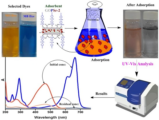
2.8. Dye Adsorption Study
3. Results and Discussion
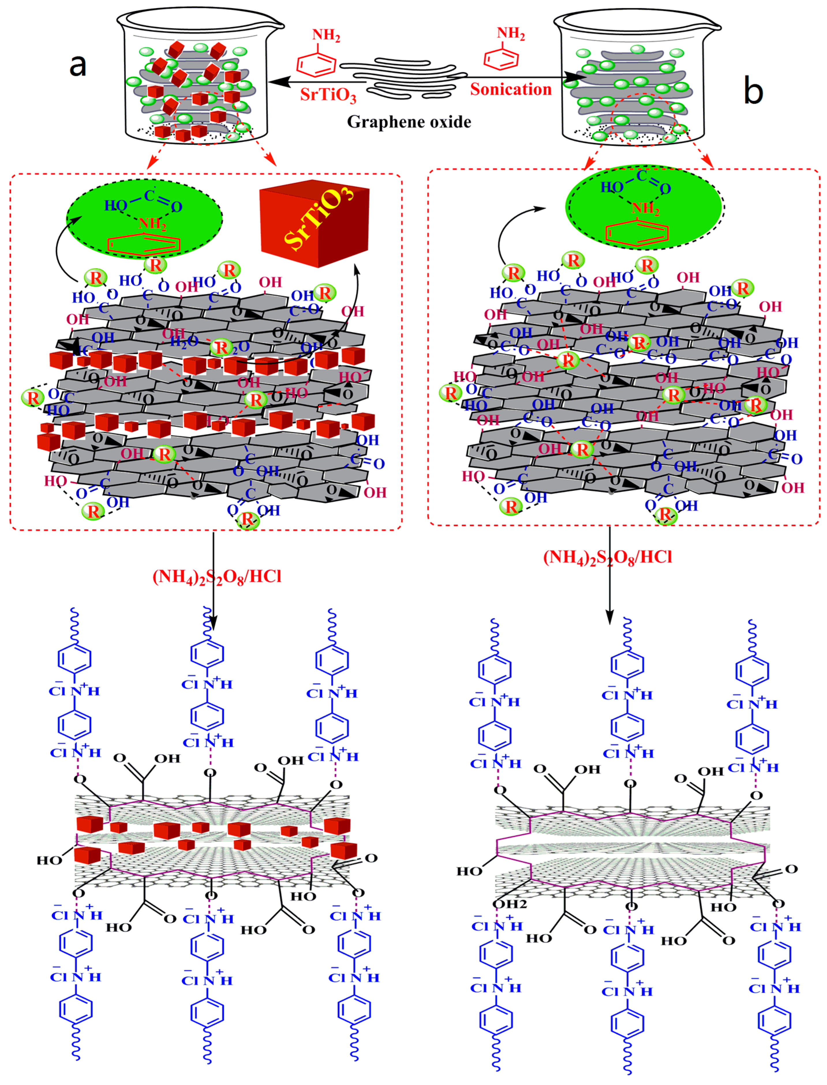
3.1. Synthesis
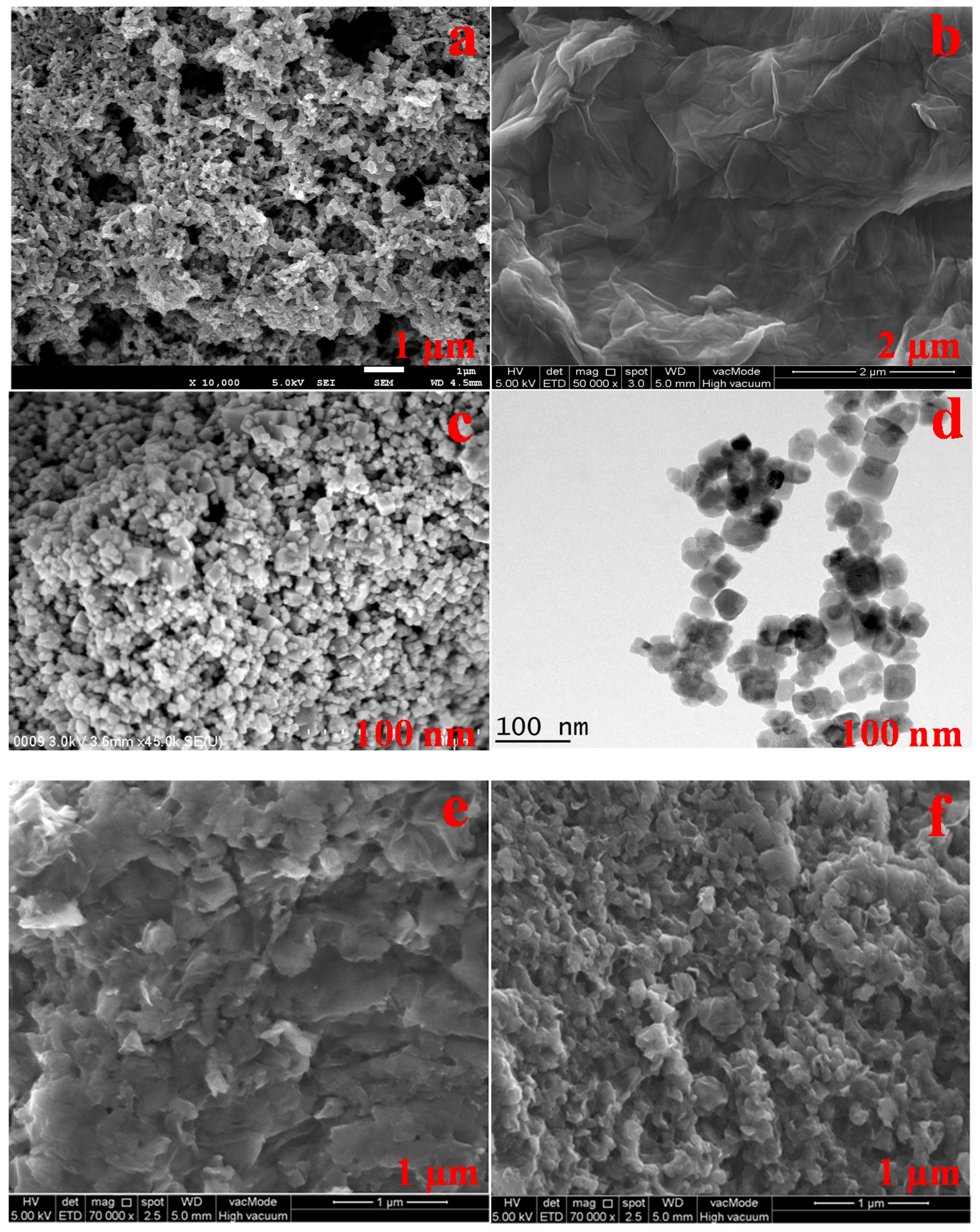
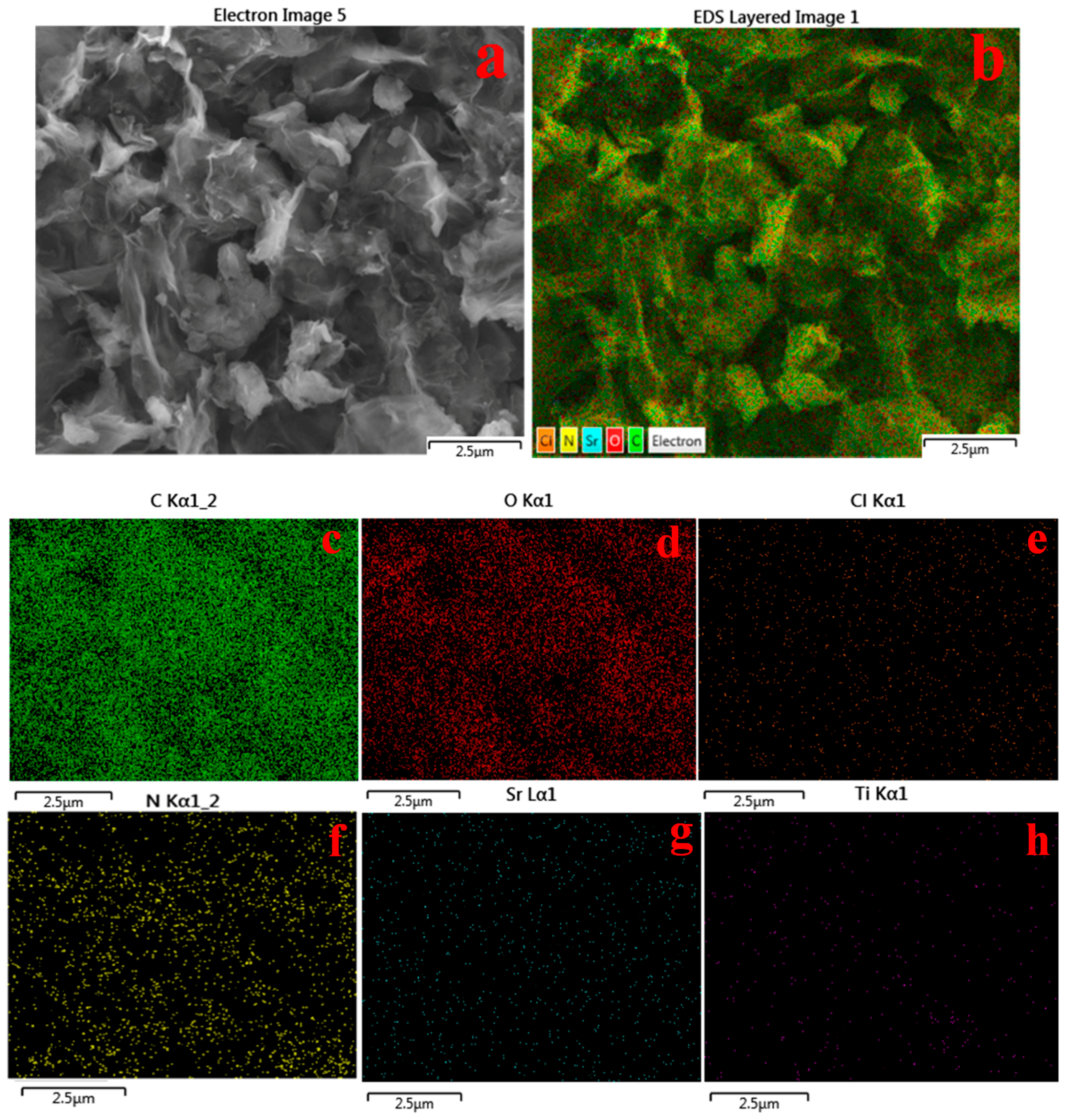
3.2. Morphological Analysis of Nanocomposites
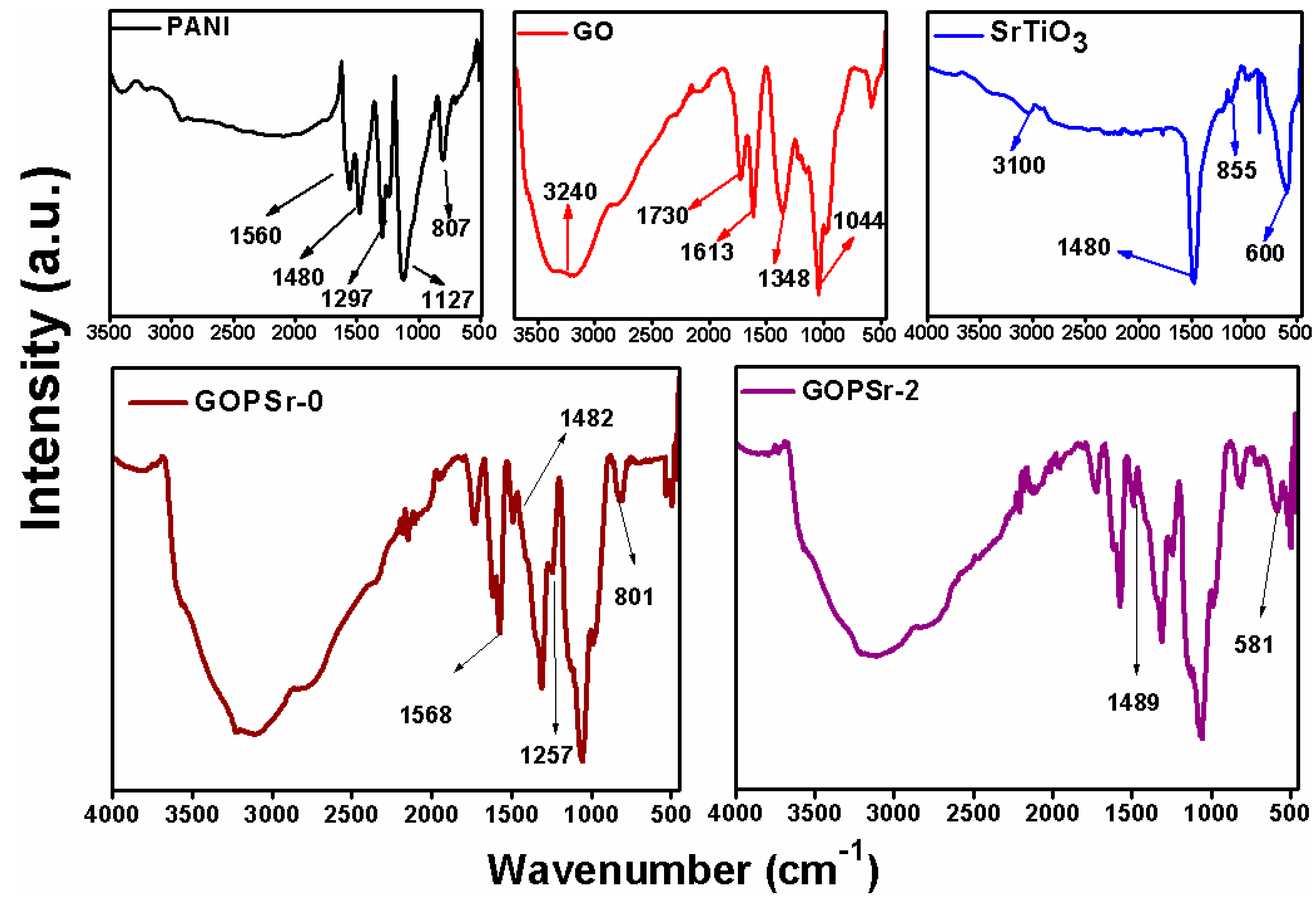
3.3. FTIR Analysis
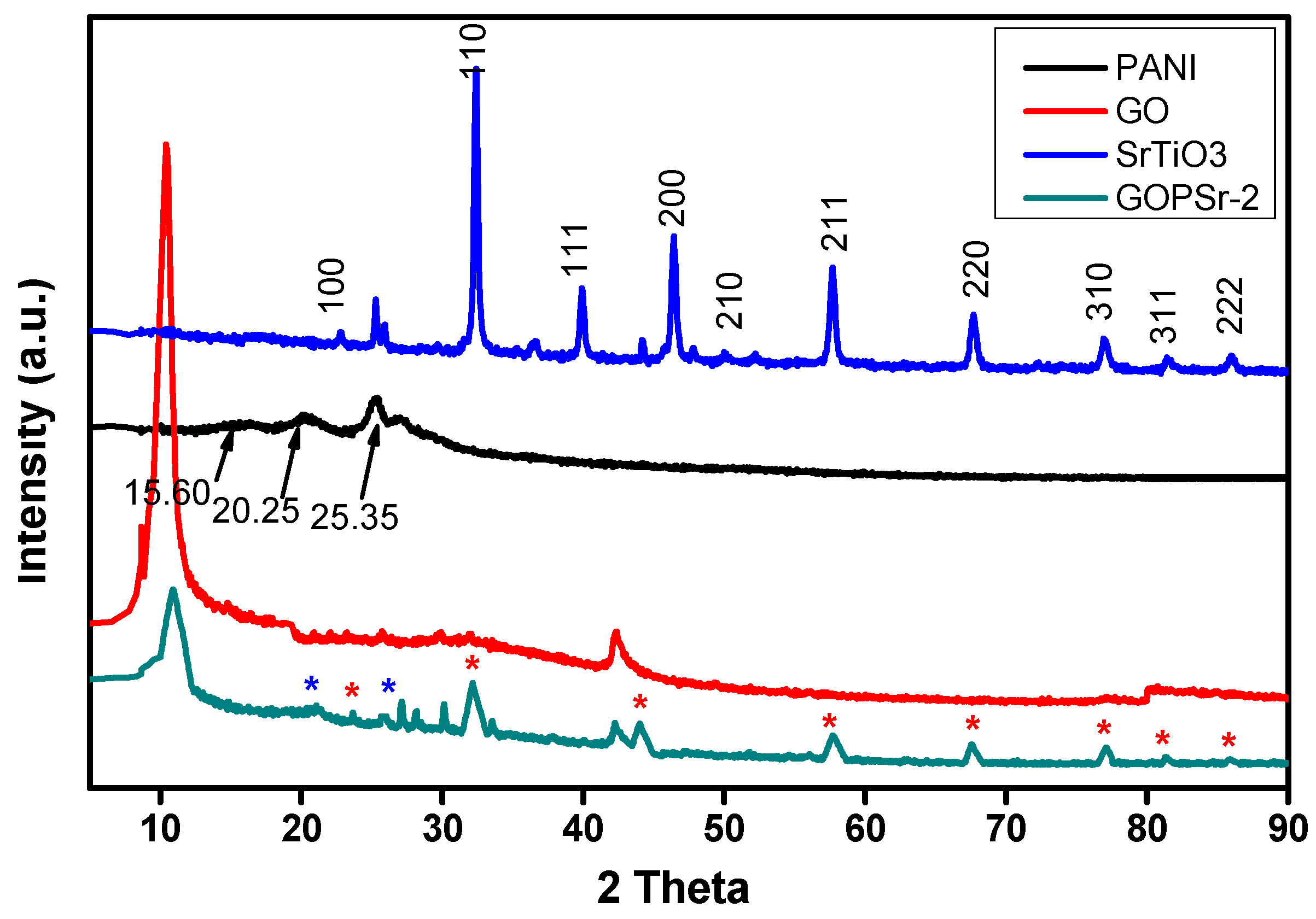
3.4. XRD Analysis
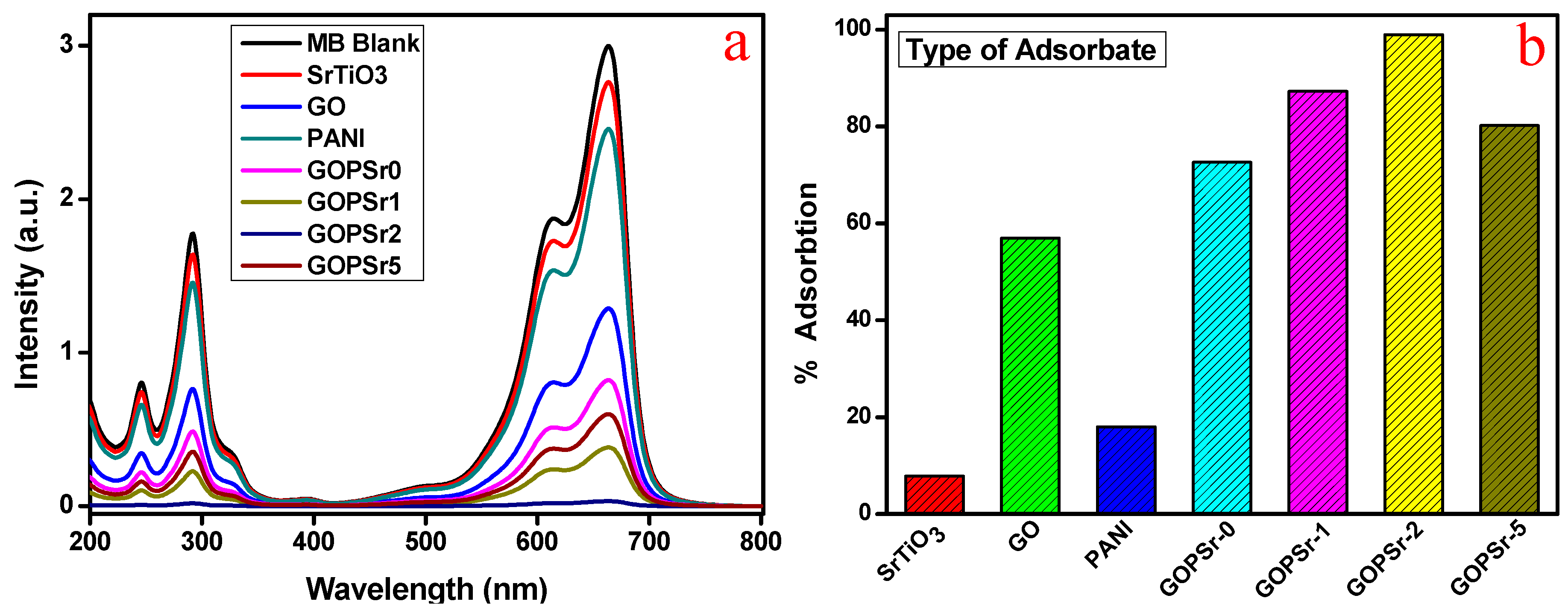
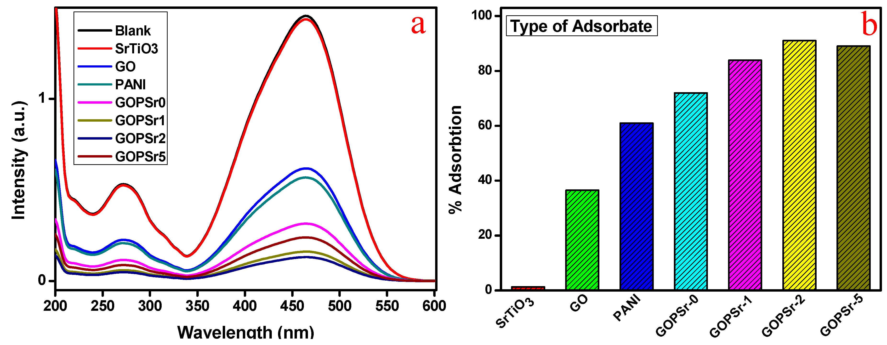
3.5. Adsorption Analysis of MB and MO
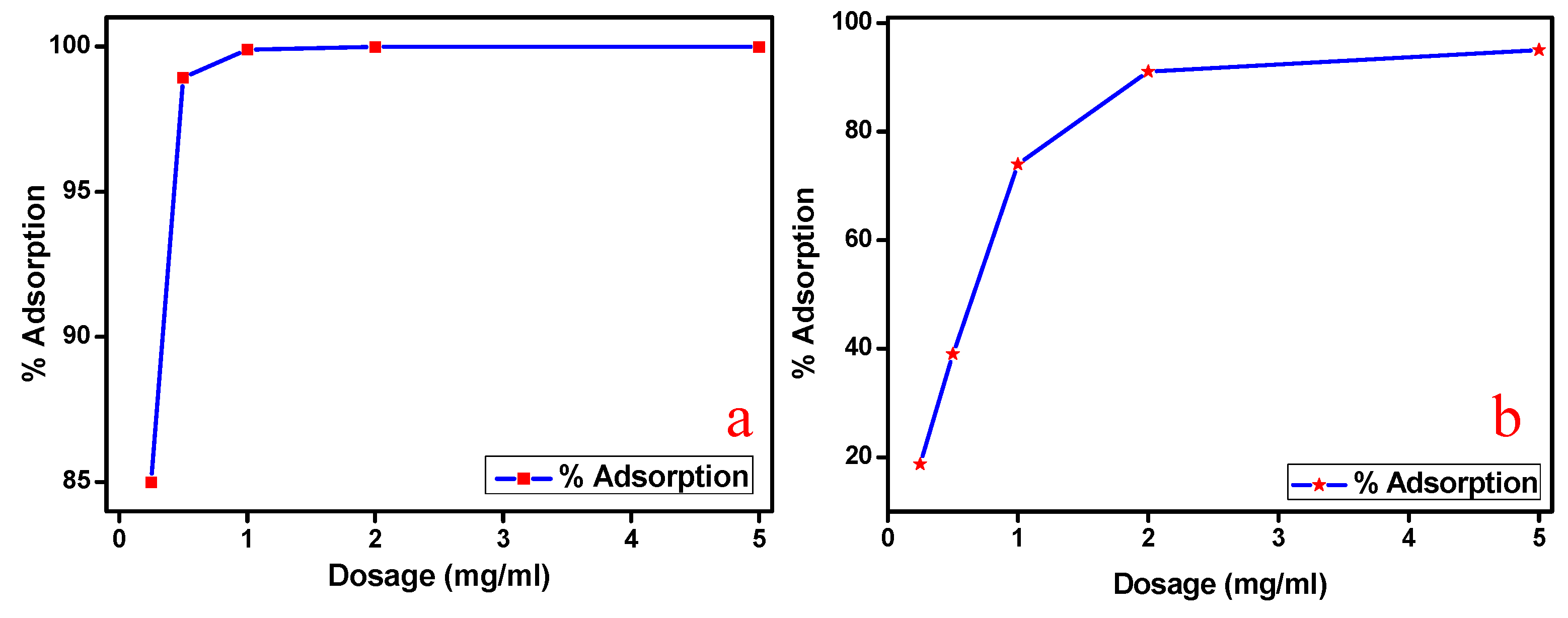
3.6. Effect of Adsorbent Dosage
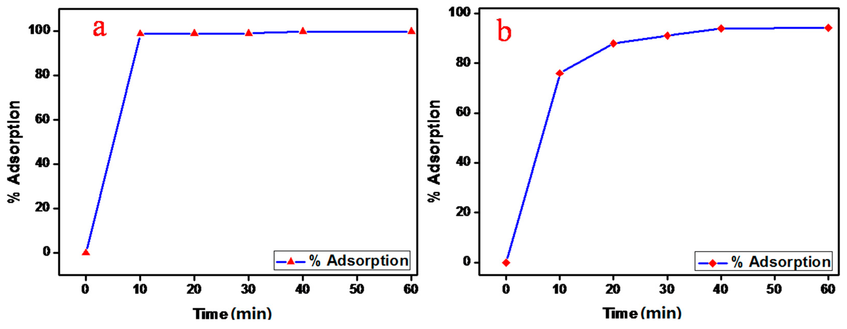
3.7. Effect of Contact Time
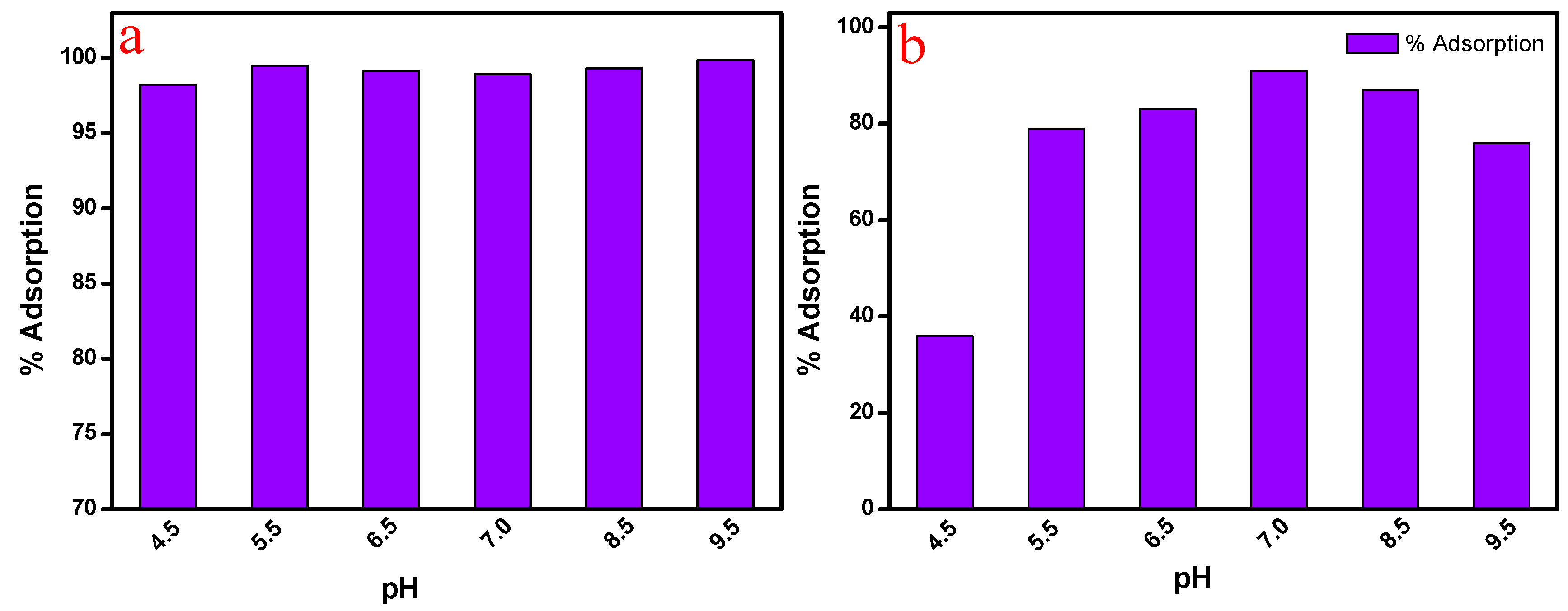
3.8. Effect of pH
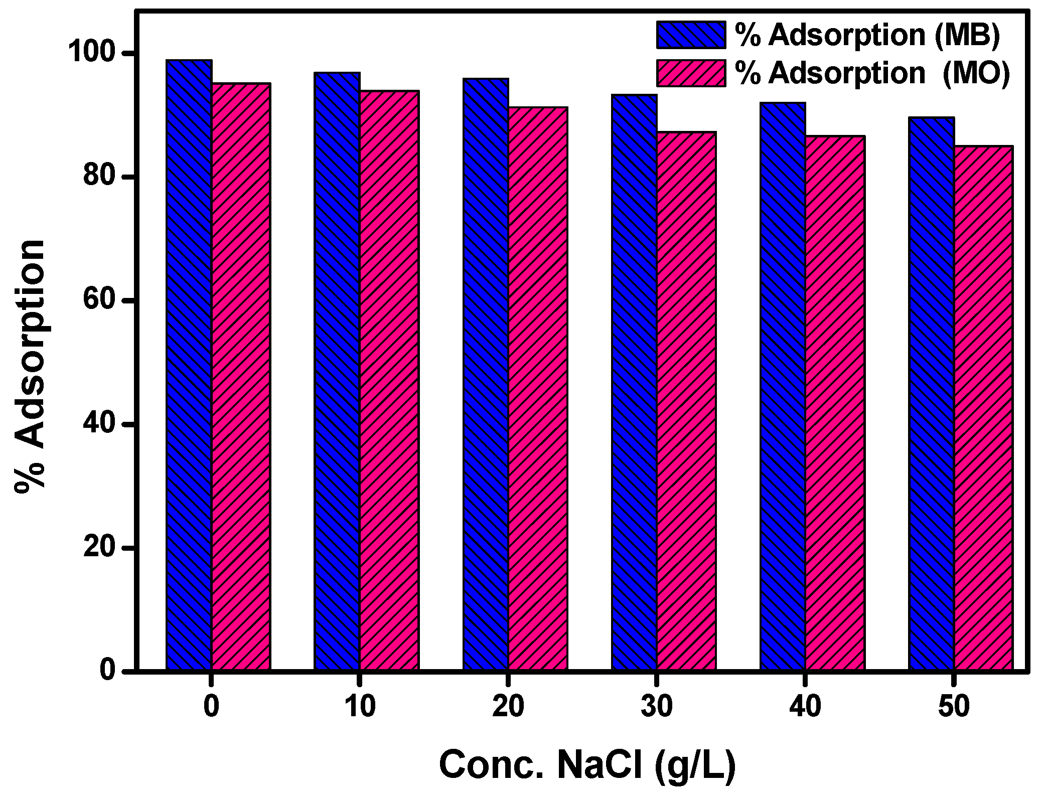
3.9. Effect of NaCl Concentration
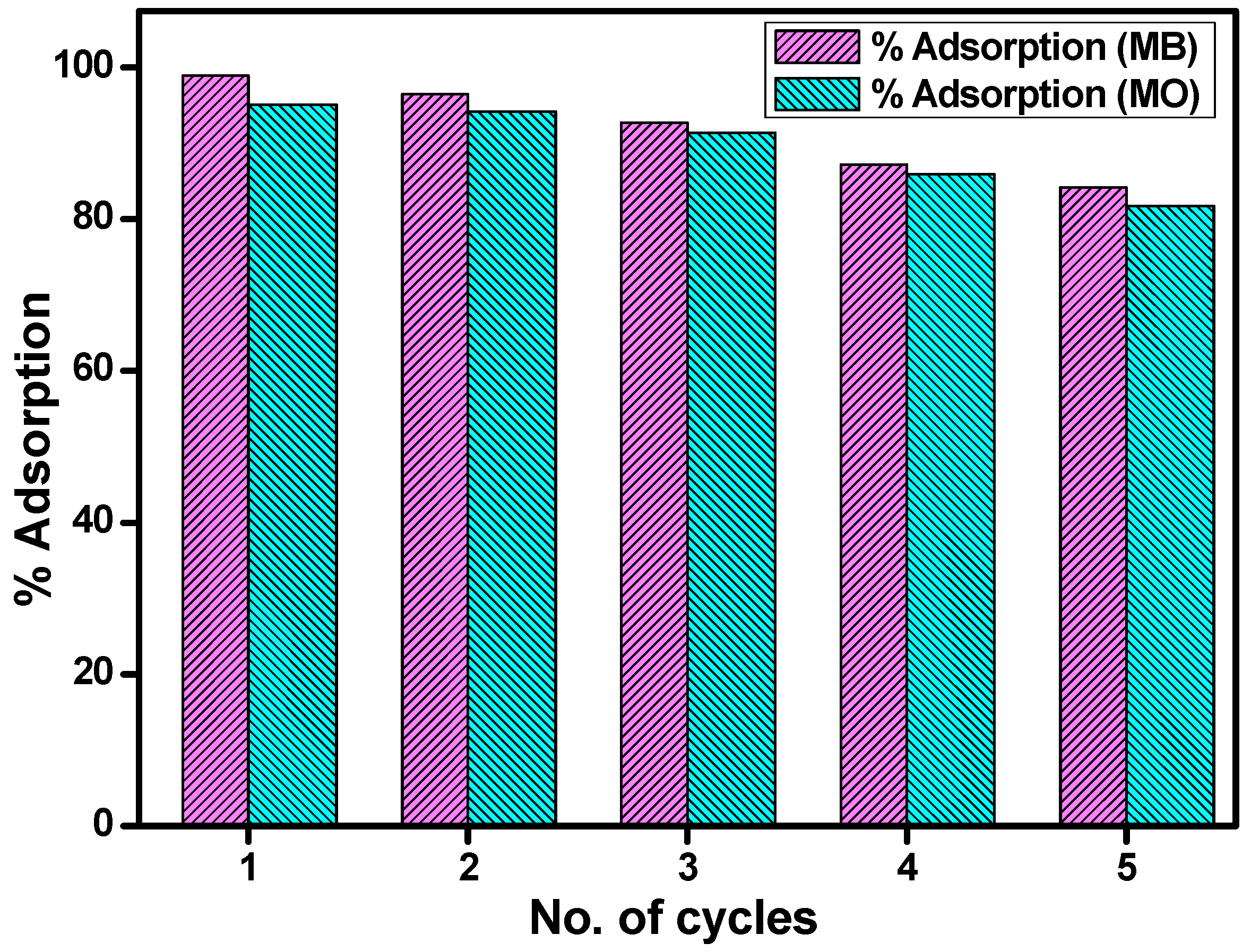
3.10. Reusability Studies
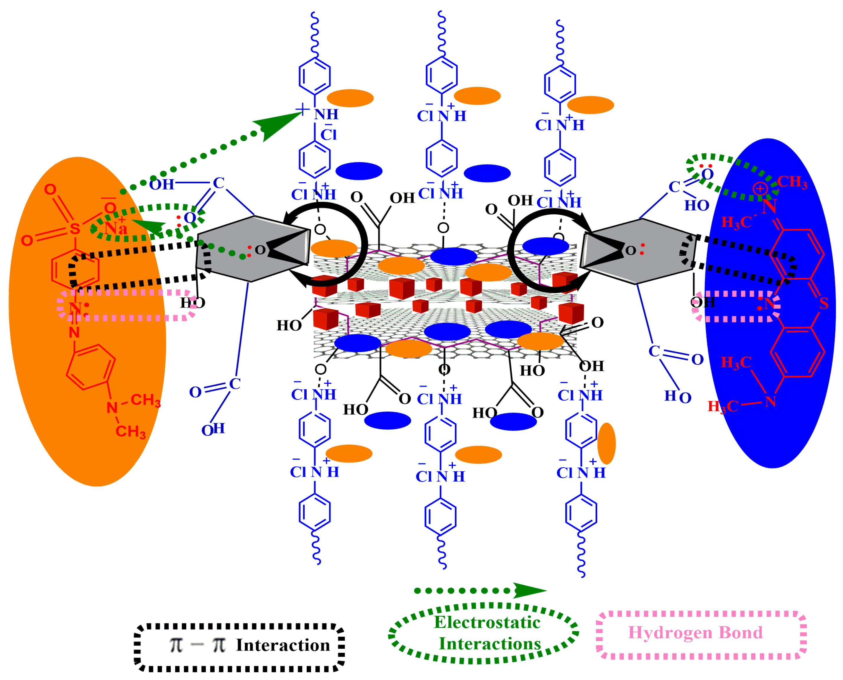
3.11. Proposed Mechanism
4. Conclusions
Supplementary Materials
Acknowledgments
Author Contributions
Conflicts of Interest
References
- Sen, T.K.; Afroze, S.; Ang, H. Equilibrium, kinetics and mechanism of removal of methylene blue from aqueous solution by adsorption onto pine cone biomass of pinus radiata. Water Air Soil Pollut. 2011, 218, 499–515. [Google Scholar] [CrossRef]
- Sokolowska-Gajda, J.; Freeman, H.S.; Reife, A. Synthetic dyes based on environmental considerations. Part 2: Iron complexes formazan dyes. Dyes Pigment. 1996, 30, 1–20. [Google Scholar] [CrossRef]
- Ivanov, K.; Gruber, E.; Schempp, W.; Kirov, D. Possibilities of using zeolite as filler and carrier for dyestuffs in paper. Papier 1996, 50, 7–8. [Google Scholar]
- Kabdaşli, I.; Tünay, O.; Orhon, D. Wastewater control and management in a leather tanning district. Water Sci. Technol. 1999, 40, 261–267. [Google Scholar] [CrossRef]
- Bensalah, N.; Alfaro, M.Q.; Martínez-Huitle, C. Electrochemical treatment of synthetic wastewaters containing alphazurine a dye. Chem. Eng. J. 2009, 149, 348–352. [Google Scholar] [CrossRef]
- Dawood, S.; Sen, T.K.; Phan, C. Synthesis and characterisation of novel-activated carbon from waste biomass pine cone and its application in the removal of congo red dye from aqueous solution by adsorption. Water Air Soil Pollut. 2014, 225, 1–16. [Google Scholar] [CrossRef]
- Yagub, M.T.; Sen, T.K.; Afroze, S.; Ang, H.M. Dye and its removal from aqueous solution by adsorption: A review. Adv. Colloid Interface Sci. 2014, 209, 172–184. [Google Scholar] [CrossRef] [PubMed]
- Chequer, F.M.D.; de Oliveira, D.P.; Ferraz, E.R.A.; de Oliveira, G.A.R.; Cardoso, J.C.; Zanoni, M.V.B. Textile Dyes: Dyeing Process and Environmental Impact; InTech Open Access Publisher: Rijeka, Croatia, 2013. [Google Scholar]
- Couto, S.R. Dye removal by immobilised fungi. Biotechnol. Adv. 2009, 27, 227–235. [Google Scholar] [CrossRef] [PubMed]
- Shahabuddin, S.; Sarih, N.M.; Ismail, F.H.; Shahid, M.M.; Huang, N.M. Synthesis of chitosan grafted-polyaniline/Co3O4 nanocube nanocomposites and their photocatalytic activity toward methylene blue dye degradation. RSC Adv. 2015, 5, 83857–83867. [Google Scholar] [CrossRef]
- Aksu, Z. Application of biosorption for the removal of organic pollutants: A review. Process Biochem. 2005, 40, 997–1026. [Google Scholar] [CrossRef]
- Shahabuddin, S.; Muhamad Sarih, N.; Mohamad, S.; Joon Ching, J. SrtiO3 nanocube-doped polyaniline nanocomposites with enhanced photocatalytic degradation of methylene blue under visible light. Polymers 2016. [Google Scholar] [CrossRef]
- Papić, S.; Koprivanac, N.; Božić, A.L.; Meteš, A. Removal of some reactive dyes from synthetic wastewater by combined Al (III) coagulation/carbon adsorption process. Dyes Pigment. 2004, 62, 291–298. [Google Scholar] [CrossRef]
- Gonzalez-Gutierrez, L.V.; Escamilla-Silva, E.M. Reactive red azo dye degradation in a UASB bioreactor: Mechanism and kinetics. Eng. Life Sci. 2009, 9, 311–316. [Google Scholar] [CrossRef]
- Zou, H.; Ma, W.; Wang, Y. A novel process of dye wastewater treatment by linking advanced chemical oxidation with biological oxidation. Arch. Environ. Prot. 2015, 41, 33–39. [Google Scholar] [CrossRef]
- Akbari, A.; Remigy, J.; Aptel, P. Treatment of textile dye effluent using a polyamide-based nanofiltration membrane. Chem. Eng. Processing 2002, 41, 601–609. [Google Scholar] [CrossRef]
- Haldorai, Y.; Shim, J.-J. An efficient removal of methyl orange dye from aqueous solution by adsorption onto chitosan/MgO composite: A novel reusable adsorbent. Appl. Surf. Sci. 2014, 292, 447–453. [Google Scholar] [CrossRef]
- Mahto, T.K.; Chandra, S.; Haldar, C.; Sahu, S.K. Kinetic and thermodynamic study of polyaniline functionalized magnetic mesoporous silica for magnetic field guided dye adsorption. RSC Adv. 2015, 5, 47909–47919. [Google Scholar] [CrossRef]
- Hosseini Koupale, E.; Alavi Moghaddam, M.; Hashemi, S. Successful treatment of high azo dye concentration wastewater using combined anaerobic/aerobic granular activated carbon-sequencing batch biofilm reactor (GAC-SBBR): Simultaneous adsorption and biodegradation processes. Water Sci. Technol. 2013, 67, 1816–1821. [Google Scholar] [CrossRef] [PubMed]
- Hu, J.; Song, Z.; Chen, L.; Yang, H.; Li, J.; Richards, R. Adsorption properties of MgO (111) nanoplates for the dye pollutants from wastewater. J. Chem. Eng. Data 2010, 55, 3742–3748. [Google Scholar] [CrossRef]
- Valix, M.; Cheung, W.H.; McKay, G. Sulfur fixation on bagasse activated carbon by chemical treatment and its effect on acid dye adsorption. Adsorption 2009, 15, 453–459. [Google Scholar] [CrossRef]
- Ma, J.; Yu, F.; Zhou, L.; Jin, L.; Yang, M.; Luan, J.; Tang, Y.; Fan, H.; Yuan, Z.; Chen, J. Enhanced adsorptive removal of methyl orange and methylene blue from aqueous solution by alkali-activated multiwalled carbon nanotubes. ACS Appl. Mater. Interfaces 2012, 4, 5749–5760. [Google Scholar] [CrossRef] [PubMed]
- Bairi, V.G.; Bourdo, S.E.; Sacre, N.; Nair, D.; Berry, B.C.; Biris, A.S.; Viswanathan, T. Ammonia gas sensing behavior of tanninsulfonic acid doped polyaniline-TiO2 composite. Sensors 2015, 15, 26415–26429. [Google Scholar] [CrossRef] [PubMed]
- Sengodu, P.; Deshmukh, A.D. Conducting polymers and their inorganic composites for advanced Li-ion batteries: A review. RSC Adv. 2015, 5, 42109–42130. [Google Scholar] [CrossRef]
- Hu, Z.; Zu, L.; Jiang, Y.; Lian, H.; Liu, Y.; Li, Z.; Chen, F.; Wang, X.; Cui, X. High specific capacitance of polyaniline/mesoporous manganese dioxide composite using Ki-H2SO4 electrolyte. Polymers 2015, 7, 1939–1953. [Google Scholar] [CrossRef]
- Bhadra, S.; Khastgir, D.; Singha, N.K.; Lee, J.H. Progress in preparation, processing and applications of polyaniline. Prog. Polym. Sci. 2009, 34, 783–810. [Google Scholar] [CrossRef]
- Shih, H.-K.; Chen, Y.-H.; Chu, Y.-L.; Cheng, C.-C.; Chang, F.-C.; Zhu, C.-Y.; Kuo, S.-W. Photo-crosslinking of pendent uracil units provides supramolecular hole injection/transport conducting polymers for highly efficient light-emitting diodes. Polymers 2015, 7, 804–818. [Google Scholar] [CrossRef]
- Baharin, S.N.A.; Muhamad Sarih, N.; Mohamad, S.; Shahabuddin, S.; Sulaiman, K.; Ma’amor, A. Removal of endocrine disruptor di-(2-ethylhexyl)phthalate by modified polythiophene-coated magnetic nanoparticles: Characterization, adsorption isotherm, kinetic study, thermodynamics. RSC Adv. 2016, 6, 44655–44667. [Google Scholar] [CrossRef]
- Boeva, Z.A.; Sergeyev, V. Polyaniline: Synthesis, properties, and application. Polym. Sci. Ser. C 2014, 56, 144–153. [Google Scholar] [CrossRef]
- Tiwari, A. Gum arabic-graft-polyaniline: An electrically active redox biomaterial for sensor applications. J. Macromol. Sci Part A 2007, 44, 735–745. [Google Scholar] [CrossRef]
- Zhao, X.; Lv, L.; Pan, B.; Zhang, W.; Zhang, S.; Zhang, Q. Polymer-supported nanocomposites for environmental application: A review. Chem. Eng. J. 2011, 170, 381–394. [Google Scholar] [CrossRef]
- Zhu, Y.; Murali, S.; Cai, W.; Li, X.; Suk, J.W.; Potts, J.R.; Ruoff, R.S. Graphene and graphene oxide: Synthesis, properties, and applications. Adv. Mater. 2010, 22, 3906–3924. [Google Scholar] [CrossRef] [PubMed]
- Golsheikh, A.M.; Lim, H.N.; Zakaria, R.; Huang, N.M. Sonochemical synthesis of reduced graphene oxide uniformly decorated with hierarchical zns nanospheres and its enhanced photocatalytic activities. RSC Adv. 2015, 5, 12726–12735. [Google Scholar] [CrossRef]
- Zhang, K.; Zhang, L.L.; Zhao, X.; Wu, J. Graphene/polyaniline nanofiber composites as supercapacitor electrodes. Chem. Mater. 2010, 22, 1392–1401. [Google Scholar] [CrossRef]
- Huang, X.; Qi, X.; Boey, F.; Zhang, H. Graphene-based composites. Chem. Soc. Rev. 2012, 41, 666–686. [Google Scholar] [CrossRef] [PubMed]
- Stoller, M.D.; Park, S.; Zhu, Y.; An, J.; Ruoff, R.S. Graphene-based ultracapacitors. Nano Lett. 2008, 8, 3498–3502. [Google Scholar] [CrossRef] [PubMed]
- Kuilla, T.; Bhadra, S.; Yao, D.; Kim, N.H.; Bose, S.; Lee, J.H. Recent advances in graphene based polymer composites. Prog. Polym. Sci. 2010, 35, 1350–1375. [Google Scholar] [CrossRef]
- Jahan, M.; Bao, Q.; Yang, J.-X.; Loh, K.P. Structure-directing role of graphene in the synthesis of metal–organic framework nanowire. J. Am. Chem. Soc. 2010, 132, 14487–14495. [Google Scholar] [CrossRef] [PubMed]
- Petit, C.; Bandosz, T.J. Enhanced adsorption of ammonia on metal-organic framework/graphite oxide composites: Analysis of surface interactions. Adv. Funct. Mater. 2010, 20, 111–118. [Google Scholar] [CrossRef]
- Jasuja, K.; Berry, V. Implantation and growth of dendritic gold nanostructures on graphene derivatives: Electrical property tailoring and Raman enhancement. Acs Nano 2009, 3, 2358–2366. [Google Scholar] [CrossRef] [PubMed]
- Wang, H.; Hao, Q.; Yang, X.; Lu, L.; Wang, X. Graphene oxide doped polyaniline for supercapacitors. Electrochem. Commun. 2009, 11, 1158–1161. [Google Scholar] [CrossRef]
- Kumar, N.A.; Choi, H.-J.; Shin, Y.R.; Chang, D.W.; Dai, L.; Baek, J.-B. Polyaniline-grafted reduced graphene oxide for efficient electrochemical supercapacitors. ACS Nano 2012, 6, 1715–1723. [Google Scholar] [CrossRef] [PubMed]
- Yong, Y.-C.; Dong, X.-C.; Chan-Park, M.B.; Song, H.; Chen, P. Macroporous and monolithic anode based on polyaniline hybridized three-dimensional graphene for high-performance microbial fuel cells. ACS Nano 2012, 6, 2394–2400. [Google Scholar] [CrossRef] [PubMed]
- Shahabuddin, S.; Sarih, N.M.; Mohamad, S.; Atika Baharin, S.N. Synthesis and characterization of Co3O4 nanocube-doped polyaniline nanocomposites with enhanced methyl orange adsorption from aqueous solution. RSC Adv. 2016, 6, 43388–43400. [Google Scholar] [CrossRef]
- Zhang, Z.; Kong, J. Novel magnetic Fe3O4@C nanoparticles as adsorbents for removal of organic dyes from aqueous solution. J. Hazard. Mater. 2011, 193, 325–329. [Google Scholar] [CrossRef] [PubMed]
- Nassar, M.Y.; Ahmed, I.S. Template-free hydrothermal derived cobalt oxide nanopowders: Synthesis, characterization, and removal of organic dyes. Mater. Res. Bull. 2012, 47, 2638–2645. [Google Scholar] [CrossRef]
- Jiao, F.; Frei, H. Nanostructured cobalt and manganese oxide clusters as efficient water oxidation catalysts. Energy Environ. Sci. 2010, 3, 1018–1027. [Google Scholar] [CrossRef]
- Hummers, W.S., Jr.; Offeman, R.E. Preparation of graphitic oxide. J. Am. Chem. Soc. 1958, 80, 1339. [Google Scholar] [CrossRef]
- Choudhury, A. Polyaniline/silver nanocomposites: Dielectric properties and ethanol vapour sensitivity. Sens. Actuators B 2009, 138, 318–325. [Google Scholar] [CrossRef]
- Azarang, M.; Shuhaimi, A.; Yousefi, R.; Moradi Golsheikh, A.; Sookhakian, M. Synthesis and characterization of ZnO NPs/reduced graphene oxide nanocomposite prepared in gelatin medium as highly efficient photo-degradation of MB. Ceram. Int. 2014, 40, 10217–10221. [Google Scholar] [CrossRef]
- Pham, V.H.; Cuong, T.V.; Hur, S.H.; Oh, E.; Kim, E.J.; Shin, E.W.; Chung, J.S. Chemical functionalization of graphene sheets by solvothermal reduction of a graphene oxide suspension in N-methyl-2-pyrrolidone. J. Mater. Chem. 2011, 21, 3371–3377. [Google Scholar] [CrossRef]
- Gopalakrishnamurthy, H.; Rao, M.S.; Kutty, T.N. Thermal decomposition of titanyl oxalates—I: Barium titanyl oxalate. J. Inorg. Nucl. Chem. 1975, 37, 891–898. [Google Scholar] [CrossRef]
- Rahy, A.; Yang, D.J. Synthesis of highly conductive polyaniline nanofibers. Mater. Lett. 2008, 62, 4311–4314. [Google Scholar] [CrossRef]
- Shi, L.; Wang, X.; Lu, L.; Yang, X.; Wu, X. Preparation of TiO2/polyaniline nanocomposite from a lyotropic liquid crystalline solution. Synth. Metals 2009, 159, 2525–2529. [Google Scholar] [CrossRef]
- Mahanta, D.; Madras, G.; Radhakrishnan, S.; Patil, S. Adsorption of sulfonated dyes by polyaniline emeraldine salt and its kinetics. J. Phys. Chem. B 2008, 112, 10153–10157. [Google Scholar] [CrossRef] [PubMed]


© 2016 by the authors. Licensee MDPI, Basel, Switzerland. This article is an open access article distributed under the terms and conditions of the Creative Commons Attribution (CC-BY) license ( http://creativecommons.org/licenses/by/4.0/).
Share and Cite
Shahabuddin, S.; Sarih, N.M.; Afzal Kamboh, M.; Rashidi Nodeh, H.; Mohamad, S. Synthesis of Polyaniline-Coated Graphene Oxide@SrTiO3 Nanocube Nanocomposites for Enhanced Removal of Carcinogenic Dyes from Aqueous Solution. Polymers 2016, 8, 305. https://doi.org/10.3390/polym8090305
Shahabuddin S, Sarih NM, Afzal Kamboh M, Rashidi Nodeh H, Mohamad S. Synthesis of Polyaniline-Coated Graphene Oxide@SrTiO3 Nanocube Nanocomposites for Enhanced Removal of Carcinogenic Dyes from Aqueous Solution. Polymers. 2016; 8(9):305. https://doi.org/10.3390/polym8090305
Chicago/Turabian StyleShahabuddin, Syed, Norazilawati Muhamad Sarih, Muhammad Afzal Kamboh, Hamid Rashidi Nodeh, and Sharifah Mohamad. 2016. "Synthesis of Polyaniline-Coated Graphene Oxide@SrTiO3 Nanocube Nanocomposites for Enhanced Removal of Carcinogenic Dyes from Aqueous Solution" Polymers 8, no. 9: 305. https://doi.org/10.3390/polym8090305
APA StyleShahabuddin, S., Sarih, N. M., Afzal Kamboh, M., Rashidi Nodeh, H., & Mohamad, S. (2016). Synthesis of Polyaniline-Coated Graphene Oxide@SrTiO3 Nanocube Nanocomposites for Enhanced Removal of Carcinogenic Dyes from Aqueous Solution. Polymers, 8(9), 305. https://doi.org/10.3390/polym8090305