Article

Epoxy-Based Shape-Memory Actuators Obtained via Dual-Curing of Off-Stoichiometric “Thiol–Epoxy” Mixtures

by
Alberto Belmonte
1,
Claudio Russo
1,2,
Veronica Ambrogi
2,3,
Xavier Fernández-Francos
4 and
Silvia De la Flor
1,*
1
Department of Mechanical Engineering, Universitat Rovira i Virgili, Av. Països Catalans 26, 43007 Tarragona, Spain
2
Department of Chemical, Materials and Production Engineering, University of Naples “Federico II”, Piazzale Tecchio, 80, 80125 Napoli, Italy
3
Institute for Polymers, Composites and Biomaterials, National Research Council of Italy, Via Campi Flegrei, 34, 80078 Pozzuoli, Italy
4
Thermodynamics Laboratory, ETSEIB, Universitat Politècnica de Catalunya, Av. Diagonal 647, 08028 Barcelona, Spain
*
Author to whom correspondence should be addressed.
Polymers 2017, 9(3), 113; https://doi.org/10.3390/polym9030113
Submission received: 14 February 2017 / Revised: 10 March 2017 / Accepted: 16 March 2017 / Published: 21 March 2017
(This article belongs to the Special Issue Functionally Responsive Polymeric Materials)

Abstract

:
In this work, epoxy-based shape-memory actuators have been developed by taking advantage of the sequential dual-curing of off-stoichiometric “thiol–epoxy” systems. Bent-shaped designs for flexural actuation were obtained thanks to the easy processing of these materials in the intermediate stage (after the first curing process), and successfully fixed through the second curing process. The samples were programmed into a flat temporary-shape and the recovery-process was analyzed in unconstrained, partially-constrained and fully-constrained conditions using a dynamic mechanical analyzer (DMA). Different “thiol–epoxy” systems and off-stoichiometric ratios were used to analyze the effect of the network structure on the actuation performance. The results evidenced the possibility to take advantage of the flexural recovery as a potential actuator, the operation of which can be modulated by changing the network structure and properties of the material. Under unconstrained-recovery conditions, faster and narrower recovery-processes (an average speed up to 80%/min) are attained by using materials with homogeneous network structure, while in partially- or fully-constrained conditions, a higher crosslinking density and the presence of crosslinks of higher functionality lead to a higher amount of energy released during the recovery-process, thus, increasing the work or the force released. Finally, an easy approach for the prediction of the work released by the shape-memory actuator has been proposed.

Graphical Abstract

1. Introduction

Shape-memory polymers (SMPs) are those materials capable of attaining and retaining a temporary-shape during a long period of time upon a so-called programming process. The programming process usually consists of a thermomechanical process in which the material is firstly heated up to a temperature close to or above a network structural transition (Tprog), then mechanically deformed to produce a desired shape, and finally cooled down to a temperature below the network structural transition while keeping the applied deformation so that the programmed shape can be retained after removal of the mechanical load [1]. Therefore, the shape-memory capability of a polymer is not an intrinsic property of the polymer, but an external procedure is necessary. Nevertheless, it demands specific network structural properties. Soft and hard phases must coexist within the network, the hard phase responsible for memorizing the permanent shape and the soft phase allowing the shape-transformation [2,3]. One of the most usual SMPs are glassy, covalently or physically crosslinked polymers, therefore the crosslinks are the hard phase and the glass transition or melting process responsible for the shape-transformation is driven by the flexible chains or soft phase [4].
Over the last years, two main branches of research have been the focus of the scientific community: on one side, the enhancement and control of the shape-memory response (SMR) by adjusting network structural parameters, changing programming and recovery conditions and modeling the behavior [5,6,7,8,9]; on the other side, the development of new and challenging SMPs in order to fulfill some inherent issues, such as the need of programming after each cycle [10,11]. Nevertheless, one of the main issues lies in the development of SMPs with complex designs demanded in a wide range of industrial applications, such as structural, aerospace and nautical applications or in the development of bioinspired devices [12,13]. In such applications, the material is commonly required to work in aggressive environments; thus, high thermal and mechanical resistance are of utmost relevance. Epoxy-based thermosets are widely used in this field of applications due to the high thermal and mechanical resistance, great insulation properties and good chemical resistance [14]. Moreover, epoxy-based SMPs have shown excellent response, with high fixation and recovery ratios as well as rapid and tunable recovery-processes [15,16]. In this sense, they are excellent candidates to fulfill the operational requirements of such applications. However, the development of complex-shaped designs is a great challenge due to the hard control of the crosslinking during the curing process of epoxy resins making difficult further processing. One approach to overcome the curing limitations lies in the use of the so-called vitrimers [17,18], crosslinked polymers which, upon thermal treatment, can modify their chemical bonds to adopt a new permanent shape. Nevertheless, this process demands high consumption of energy for the network reconfiguration to take place and could lead to undesired final properties. Our research group has recently shown an effective approach to obtain complex-shaped epoxy-based materials through a two stage curing procedure. The sequential dual-curing of off-stoichiometric “thiol–epoxy” mixtures using tertiary amines as catalyst leads to the formation of an intermediate, stable, solid-like and conformable material after an initial and low energy consuming polymerization process (the “thiol–epoxy” polycondensation), that can be further processed into several complex shapes which are fixed through a second polymerization step triggered at higher temperature (the epoxy homopolymerization of the remaining epoxy groups) [19,20].
The great advantage on using such dual-curing methodology is the possibility of preparing materials with easy and efficient control of the final network structural properties, enhancing the thermomechanical properties of the common click “thiol–epoxy” thermosets. Through different “thiol” and “epoxy” compounds and varying the “thiol–epoxy” ratio of the off-stoichiometric mixture, a wide range of materials are produced: from low to highly crosslinked network structures, homogeneous and tailored glass transition processes and highly deformable glassy materials [19]. Moreover, these materials are potential candidates for shape-memory applications. On the one hand, it has been shown that the “thiol–epoxy” network leads to SMPs with enhanced response: high performance fixing and recovering the original shape, rapid recovery-process, high strength and extended deformation limits [21,22,23]. On the other hand, thanks to the possibility of forming complex-shaped designs, the final material is an interesting candidate for many of the mentioned applications.
To this end, in this study, we focus on the characterization of these materials as potential shape-memory polymers for actuation purposes. Shape-memory actuators are widely used in industrial applications as smart mechanisms for autonomous control. Taking into account that real operational scenarios usually involve flexural instead of tension or compression actuation designs, bent-shaped SMPs with different network structural properties have been processed from the intermediate material. The performance has been analyzed using the DMA equipment, which allows precise analysis and total control in flexural mode. In order to fully characterize the shape-memory response as an actuator, experiments in unconstrained, partially-constrained and fully-constrained conditions have been carried out, thus, from completely free-recovery conditions, passing through real situations in which the SMP behaves against an external force, to the fully impeded condition in which a recovery-force instead of shape is generated. Moreover, in order to enhance and evaluate the actuation performance, a highly functional epoxy resin, EponTM SU8, has been incorporated in a specific amount to the “thiol–epoxy” networks. It is known that the increase of the crosslinking density and the nature of the crosslinks have a crucial effect in the efficiency storing and releasing the energy associated to the shape-memory effect (SME) [5,24,25]. Taking into account the above, the incorporation of a large and spatially hindered molecule chemically attached to the network is expected to enhance the actuation performance.

2. Experimental Section

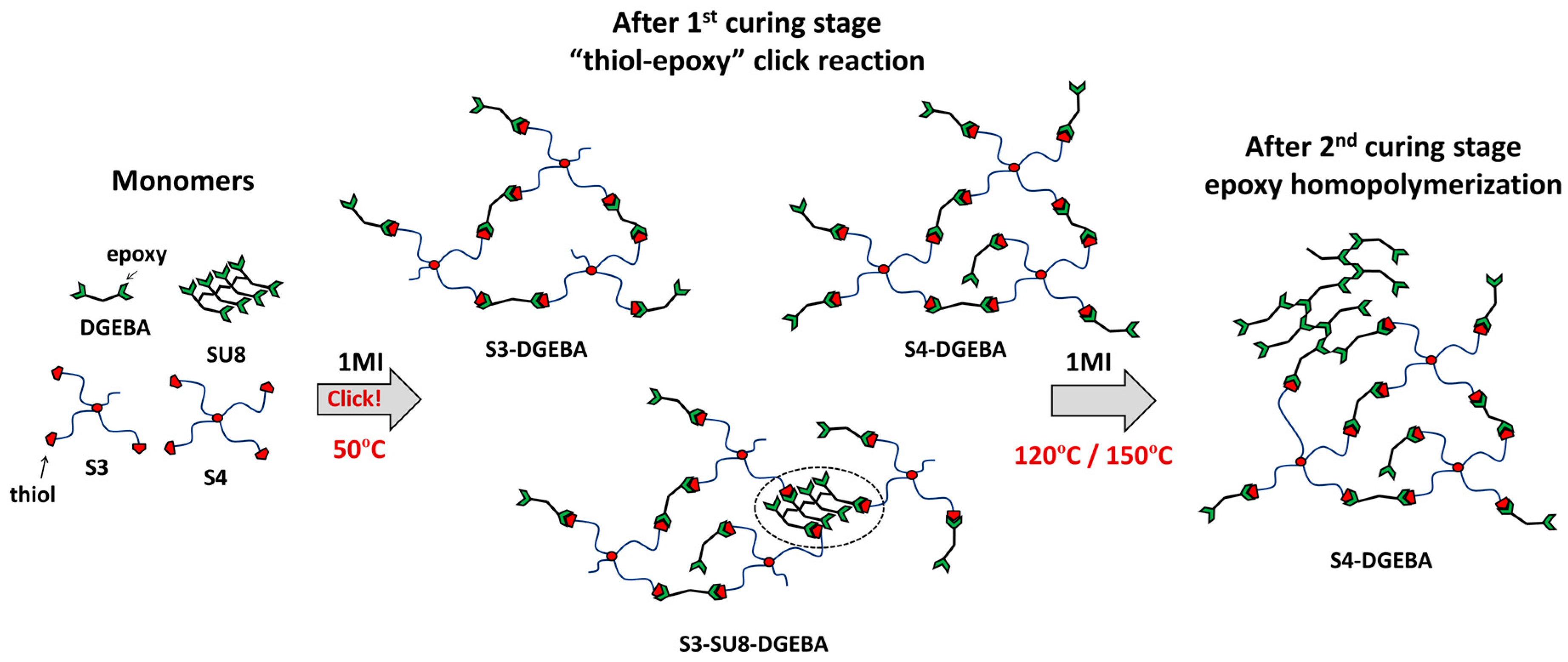
2.1. Materials and Methodology

Diglycidyl ether of bisphenol A (DGEBA, GY240, Huntsman, Everberg, Belgium) with an epoxy equivalent weight of 182 g/eq. was used as the main epoxy resin. EPONTM resin SU8 with an epoxy equivalent average weight of 215 g/eq. was used as a highly functional network modifier (average functionality of 8 epoxy groups per molecule) in a molar proportion of 3:7 (SU8:DGEBA). Pentaerythritoltetrakis (3-mercaptopropionate) (S4) with a thiol equivalent weight of 122.17 g/eq. and trimethylolpropane tris(3-mercaptopropionate) (S3) with a thiol equivalent weight of 132.85 g/eq. (Sigma-Aldrich, St. Louis, MO, USA) were used as curing agents in an under-stoichiometric proportion with respect to the epoxy groups in the system. 1-methylimidazole (1MI) with a molecular weight of 82.1 g/mol (Sigma-Aldrich, St. Louis, MO, USA) was used as catalyst in a proportion of 1 phr (parts of catalyst per hundred parts of the whole mixture). The DGEBA was dried under vacuum overnight at 80 °C before use. The other reagents were used as received without further purification.
Different off-stoichiometric “thiol–epoxy” systems were chosen in order to study the SMR in relation with the network structural properties. The composition of the different formulations is shown in Table 1. According to our previous work [19], mixtures of DGEBA with both S3 and S4 thiol compounds separately, were chosen as the main systems of study. In addition, the SU8 resin was added in a specific proportion to the S3-DGEBA system in order to study the effect of incorporating a highly functional and large molecule in the network structure with the SMR. The SU8:DGEBA weight ratio was 3:7 to ensure a substantial increase of the Tg and crosslinking density while avoiding the formation of extremely brittle materials. The S4-DGEBA system was not considered due to the formation of extremely brittle materials when adding very small amounts of SU8 which do not satisfy the requirements for shape-memory purposes.
For each system, different “thiol–epoxy” ratios were chosen to study the effect of increasing the amount of epoxy excess with the SMR. Taking advantage of the characterization done in our previous work [19], the ratios were selected from the critical ratio (rc), which is the minimum “thiol–epoxy” ratio to form a gelled and therefore solid-like and conformable intermediate material after the 1st curing stage, up to a ratio in which both, the intermediate and final materials, have very similar properties and therefore the duality of the system is lost in terms of applicability. From the experimental data, it has been considered r = 0.9 the upper limit. In this way, all the formulations of study allow the processing of bent-shaped designs for the further shape-memory characterization as actuators. The rc of the new system of study (S3-SU8-DGEBA) has been determined following the same experimental procedure as in our previous work [19]: intermediate materials cured from the theoretical rc (calculated using the Flory equation) were heated up and the physical behavior observed. Non-gelled networks lead to undesired material flow and therefore shape-loosing. By increasing the “thiol–epoxy” ratio, the flow is reduced until no shape-loosing is appreciated. This ratio is then checked through rheological analysis to confirm that gelation is taking place and therefore it is stipulated as the rc. The rc of the three systems of study are summarized in Table 1.
Once the rc are determined, the “thiol–epoxy” ratios of study have been experimentally determined by trial and error as follows: starting from r = rc and increasing by 0.05, bent-shaped samples were prepared and a flat temporary-shape was programmed following the shape-memory programming procedure explained in the next section. In some systems, samples with ratios too close to rc could not allow such level of deformation during the programming process and broke. The first ratio in which the sample did not break was stipulated as the initial ratio. From this ratio, increasing by 0.1 each time, the other formulations were defined until r ≤ 0.9. Therefore, the selected formulations of study are (S3-DGEBA-r = 0.65/0.75/0.85), (S4-DGEBA-r = 0.6/0.7/0.8) and (S3-SU8-DGEBA-r = 0.6/0.7/0.8). As can be seen, the role of the epoxy excess in the deformation level is the crucial parameter in these systems. Regardless of rc, in both S4-DGEBA and S3-SU8-DGEBA, working at r < 0.6 leads to very brittle materials for such deformation level.
The formulations without SU8 were prepared by pouring the compounds in a glass vial and manually stirring until a homogeneous liquid was attained. In the case of the formulation containing SU8, the DGEBA and SU8 resins were previously mixed by dissolving them in dichloromethane to ensure a homogeneous and compatible mixture. The solvent was then released under vacuum, stirring and temperature. Afterwards, the mixture was cooled down to room temperature and the S3 and 1MI reagents were poured in and the whole mixture manually stirred.

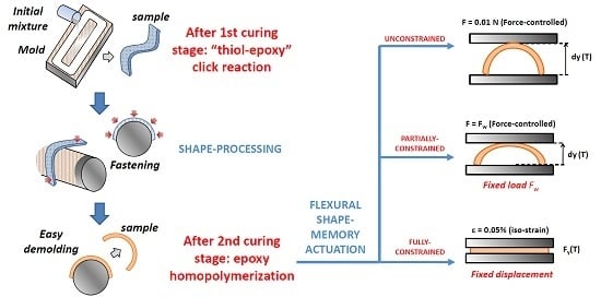
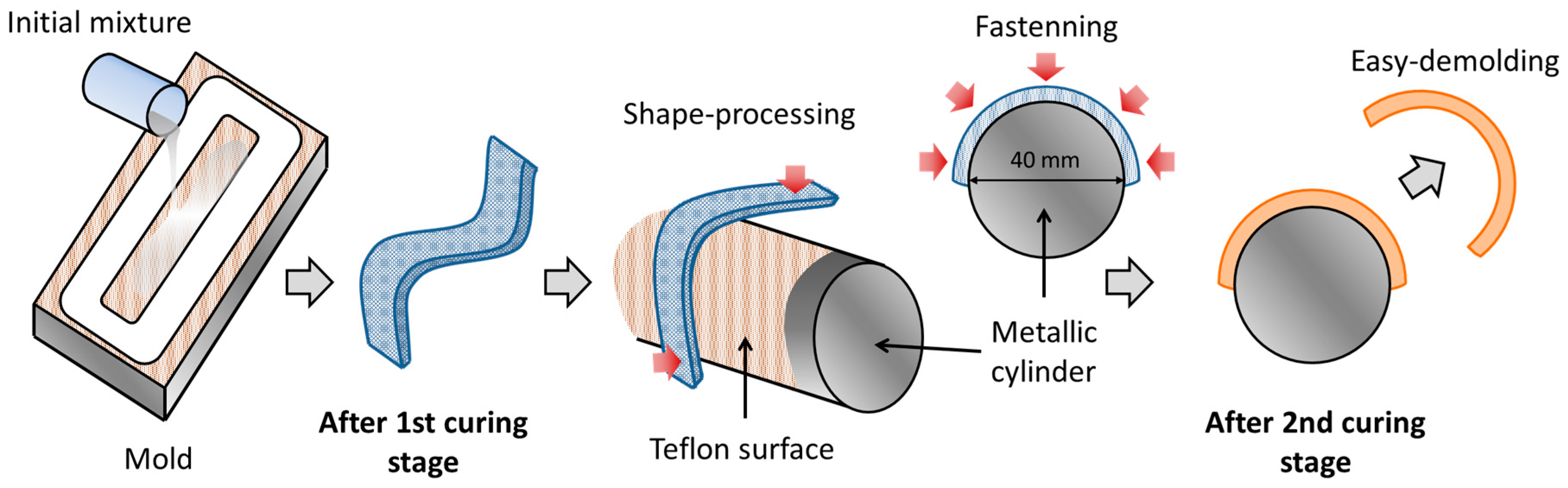
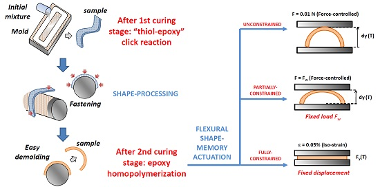
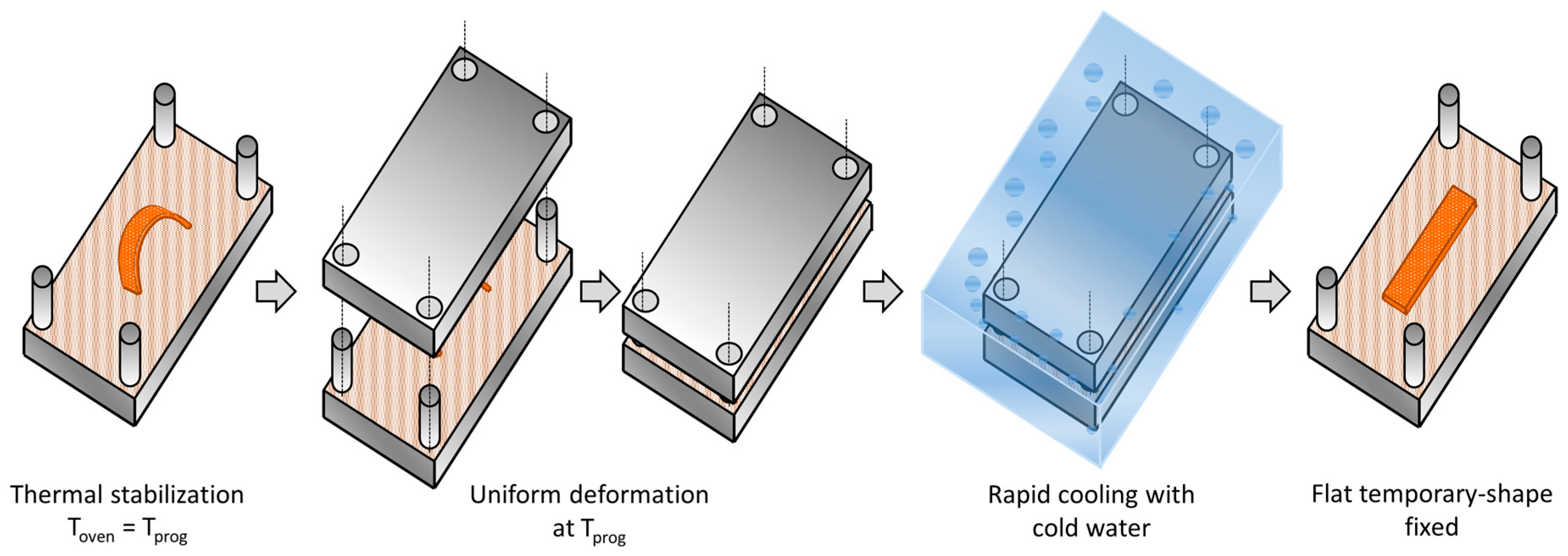
2.2. Sample Processing

Taking advantage of the sequential dual-curing system, it is possible to obtain complex-shaped materials in an easy, efficient and most important, reproducible manner. In this study, bent-shaped SMPs have been processed in order to analyze the SMR in flexural mode; from a flat temporary-shape to the original bent-shape, thus, recreating one of the most usual working designs of an actuator. The entire process to obtain the bent-shaped samples is depicted in Figure 1. First, the initial mixture is prepared as described in the previous section. Once the mixture is prepared, it is rapidly poured into a mold to obtain an intermediate prismatic-shaped material with specific dimensions. The first curing stage is carried out at 50 °C during 3 h to ensure the completion of the “thiol–epoxy” polycondensation [20]. Afterwards, thanks to the high deformability of the intermediate material, it is easily molded onto a metallic cylinder of 40 mm diameter covered with a Teflon layer to obtain the desired level of curvature in the sample. The Teflon layer avoids the sample adhesion onto the metallic surface after the second curing stage. Then, in order to impede the recovery of the original shape due to the viscoelastic response during the temperature increase for the second curing stage, the sample is fastened with minimal force (using sticky Teflon film) onto the cylinder surface. Finally, the second curing stage is carried out at 120 °C for 1 h followed by 1 h at 150 °C to ensure the completion of the epoxy homopolymerization [20].
Once the sample is prepared, it is polished in order to eliminate any defects in the surface and to fit the specific dimensions, thus ensuring reproducibility and making possible a safe and meaningful comparison between samples from different formulations and experimental conditions. In Figure 2, a scheme of the sample final dimensions and a photograph of the bent-shaped samples are shown. The deflection, “d”, is determined from the lower side of the sample and the other dimensional parameters as schematized.

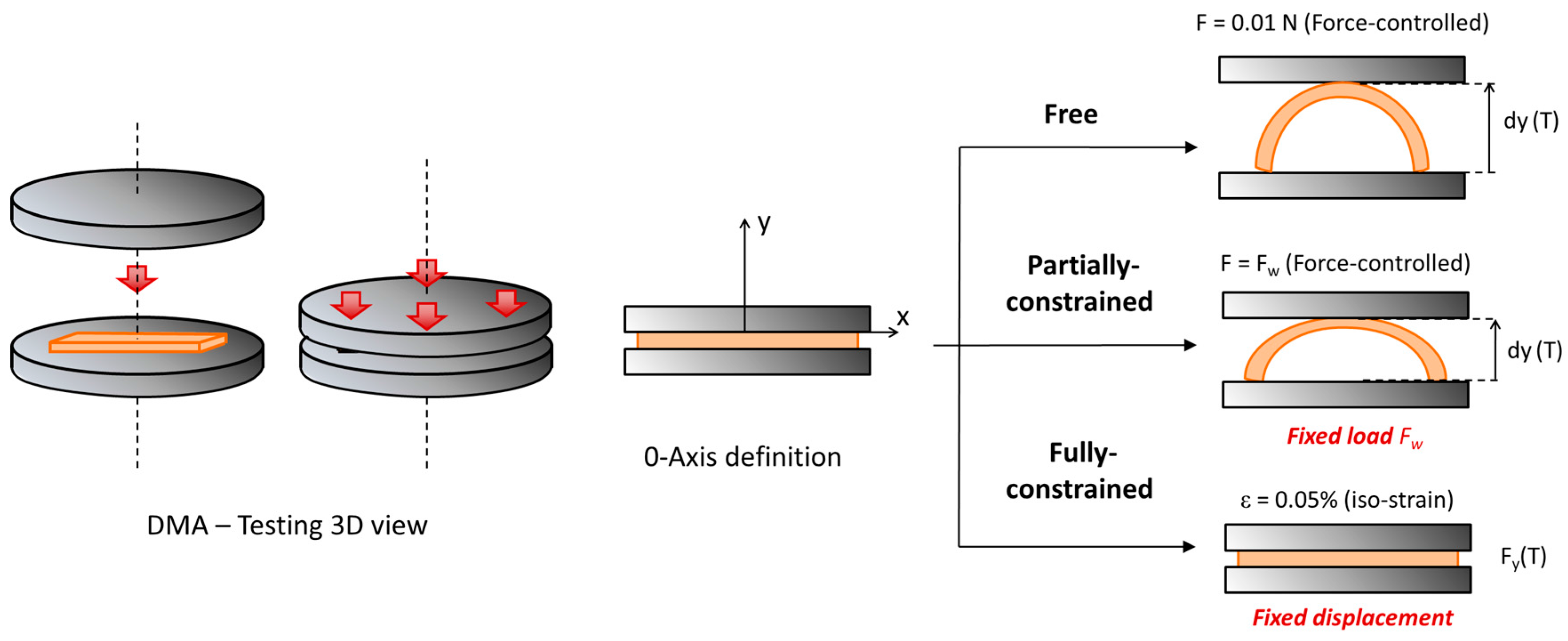
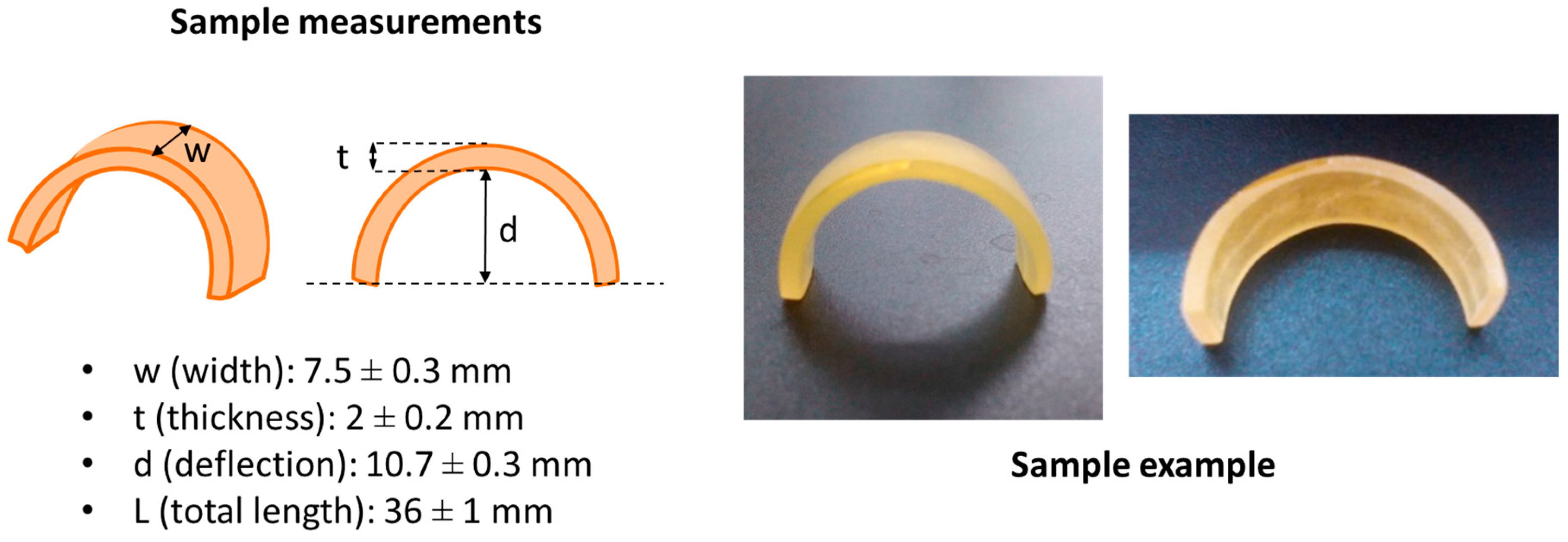
2.3. Thermomechanical Characterization

The S3-SU8-DGEBA system was characterized using a Differential Scanning Calorimeter (DSC) Mettler 821e, calibrated with indium standards. A preliminary characterization of the curing process of S3-SU8-DGEBA formulations was carried at 10 °C/min. Materials with different “thiol–epoxy” ratios ranging from 0 to 1 (0/0.25/0.5/0.75/1) were prepared and analyzed following the same procedure as for the S3-DGEBA and S4-DGEBA systems in our previous work [19]. The intermediate materials were cured in a conventional oven at 50 °C during 3 h. Then, a piece of around 5 mg was analyzed in the DSC from −50 °C up to 100 °C at 10 °C/min. For the final materials, after the 3 h of curing at 50 °C in the oven, a post-curing of 1 h at 120 °C followed by 1 h at 150 °C was imposed and then a piece of around 5 mg was analyzed in the DSC from 30 °C up to 200 °C at 10 °C/min. The glass transition temperatures of the intermediate and final materials were determined as the halfway point in the heat capacity step taking place during the glass transition.
Dynamic mechanical analysis of the formulations of study (S3-DGEBA-r = 0.65/0.75/0.85), (S4-DGEBA-r = 0.6/0.7/0.8) and (S3-SU8-DGEBA-r = 0.6/0.7/0.8) were performed using a DMA Q800 TA Instruments, equipped with a 3-point-bending clamp (15 mm), in oscillation mode at 1 Hz and 0.1% of amplitude strain and imposing a temperature ramp of 3 °C/min. The glassy (Eg) and rubbery (Er) moduli were determined at 40 °C and Tg + 30 °C, respectively. The Tg was determined as the tanδ peak temperature. The height of the peak and width at half-height (FWHM) of the tanδ curve were also determined. The relation between Eg and Er was calculated as a measure of the SMR (efficiency fixing the temporary-shape and recovering the original shape).

2.4. Shape-Memory Characterization

The shape-memory characterization was divided in two steps: programming of the temporary-shape and recovery of the original shape. For the programming of the temporary-shape, a tailor-made device consisting of male and female stainless steel plates of 15 × 8 cm2 of surface was used. In order to produce an equal, homogeneous and controlled pressure over the sample during the programming, the thickness of the female part was fitted to weigh 0.5 kg. The programming procedure is schematized in Figure 3: the male part of the device with the bent sample placed on it, and the female part were introduced separately in a preheated oven at the programming temperature Tprog = Tg + 30 °C and held during 30 min for thermal stabilization in order to ensure that the network structure of the material is fully relaxed before programming. Afterwards, the female part of the device was fitted to the male part, and its weight produced the flattening of the sample. The whole assembly was placed immediately inside a bath with cold water for 1 min to ensure that the sample temperature decreased below the network relaxation temperature and therefore fix the temporary-shape. Finally, the female part was removed and the flat sample was wiped dry using a paper towel.
Once the samples were programmed, the recovery of the original shape was carried out using the DMA equipped with the compression clamp (diameter of 40 mm) at different operational modes depending on the experiment performed: unconstrained, partially-constrained or fully-constrained recovery conditions. The sample mounting and the recovery analysis is depicted in Figure 4: in unconstrained-recovery experiments, the DMA was set in Force-controlled mode and a minimal force of 0.01 N was imposed to register the recovery-process. The displacement of the moveable clamp, dy(T), was recorded as a measure of the shape-recovery (SR), which was determined applying Equation (1). It should be note that in Equation (1) the maximum displacement is defined by the deflection, “d”, of the original shape.
The instantaneous shape-recovery speed, SRspeed(T), was calculated using Equation (2) as a measure of the shape-recovery sharpness. Using the SRspeed(T) curve, the temperature at which the maximum recovery speed is found was determined as the peak of the curve (Tpeak), and the duration of the process as the width of the curve at half-height (∆Tpeak). Additionally, common shape-memory quantifiers, such as, the shape-recovery rate (Vr) and the shape-recovery ratio (Rr) were determined for comparison purposes among the different formulations. Vr was determined from SR(T1) = 0.15 to SR(T2) = 0.85 applying Equation (3) and Rr applying Equation (4), where dy(Tend) is the displacement reached by the moveable clamp at the end of the recovery-process.
S R ( T ) = 1 d d y ( T ) d
S R speed ( T ) = S R ( T ) d T
V r = S R 15 % 85 % T SR 15 % 85 % · d T d t
R r = d y ( T end ) d · 100
The partially-constrained experiments were carried out in Force-controlled mode applying a constant force (Fw) equal in all the experiments. The displacement of the moveable clamp was recorded and the shape-recovery was measured using Equation (1). Applying Equation (2), the SRspeed(T) curve was calculated and both Tpeak and ∆Tpeak were determined as explained above. Additionally, the relative work, Wrel, developed by the sample was determined both, experimentally and theoretically, using Equation (5) (in mN·mm/mm). In this expression, the final displacement reached, dy(Tend), has been normalized with respect to the maximum displacement, “d”, for comparison purposes.
W rel = F w · d y ( T end ) d
For the calculus of the theoretical relative work, Wrelt, it has been taken into account that all the force given by the sample during the SME is equal to the force given to program the sample into the temporary-shape (Fprog). Fprog can be approached using the beam deflection formula for small deformations given by Equation (6).
F prog = 4 · ( d + t 2 ) · E ( T prog ) · w · t 3 L 3
where “d” is the deflection of the sample, E(Tprog) is the modulus at the programming temperature, considered constant and equal to the relaxed modulus Er, and “w”, ”t” and “L” are the dimensions of the sample (width, thickness and length, respectively). Once Fprog is determined, the theoretical displacement reached, dy(Tend), can be determined reordering Equation (6) into (7) and taking into account the force applied by the DMA, Fw, behaving in opposite direction during the recovery experiment. Then, by simply applying Equation (5), Wrelt is determined.
d y ( T end ) = ( F prog F w ) 4 · L 3 · E ( T prog ) · w · t 3 t 2
The fully-constrained experiments were performed at Iso-Strain mode imposing 0.05% of strain in order to measure the force generated by the sample, Fy(T), during the recovery-process. In the same way as for the unconstrained and partially-constrained experiments, Tpeak and ∆Tpeak were determined from the derivative curve, dFy(T)/dT. As proposed by Li and Wang [26], Fy(T) can be divided in different components as shown in Equation (8). Fresidual(T) is the force generated due to incomplete stress relaxation during the programming process. In our case, it can be neglected since the programming process is performed at Tprog >> Tg, thus, the sample is able to relax all the structural changes during the programming. Fthermal(T) is the force generated due to the thermal expansion of the sample and it depends on the contact area of the sample with the DMA clamp. FSR(T) is the force generated due to the SME during the mechanical relaxation and it depends on the programming and recovery time-temperature conditions.
F y ( T ) = F SR ( T ) + F residual ( T ) + F thermal ( T )
The thermal force, Fthermal(T), has a crucial role and, in contrast with common experiments carried out in tension mode, it acts in the same direction of the SME. It can be approached by applying Equation (9), which takes into account the variation of the modulus with the temperature.
F thermal =   E ( T ) · α ( T ) · ( T T 0 ) · S eff
where E(T) is the modulus at temperature “T”, α(T) is the thermal expansion coefficient which can be considered a constant value in the ranges T < Tg and T > Tg (4.5 × 10⁻⁵ and 6.0 × 10⁻⁶ °C−1 respectively, values obtained from common epoxy materials in the literature [27]). T0 is the initial temperature (T0 = 30 °C in all the experiments) and “Seff” is the effective section (section in contact with the DMA clamp). Theoretically, in a compression experiment “Seff” would be the whole contact surface (width x length) of the sample; however, in spite of the good fixation of the temporary-shape, some residual shape-recovery takes place, therefore the effective surface approaches a punctual contact instead. To better calculate “Seff”, one can take advantage of the force given by the DMA to keep the imposed ε of 0.05%. This force is applied at room temperature and therefore, by simply applying Hooke’s law it is possible to obtain the real surface in which it is being applied (see Equation (10)).
S eff =   F DMA E g · ε
where Eg is the modulus in the glassy state (at T0 = 30 °C) and ε is the imposed deformation in the experiment (0.05%).
Finally, the force generated due to the SME during the mechanical relaxation, FSR(T), has been determined by subtracting Fthermal(T) from Fy(T). From this curve, the total shape-recovery force FSR has been determined as the force gained between the onset and offset points. Note that the force generated in fully-constrained experiments shows the typical behavior of the network relaxation processes, thus, an onset and offset points can be defined.

3. Results and Discussion

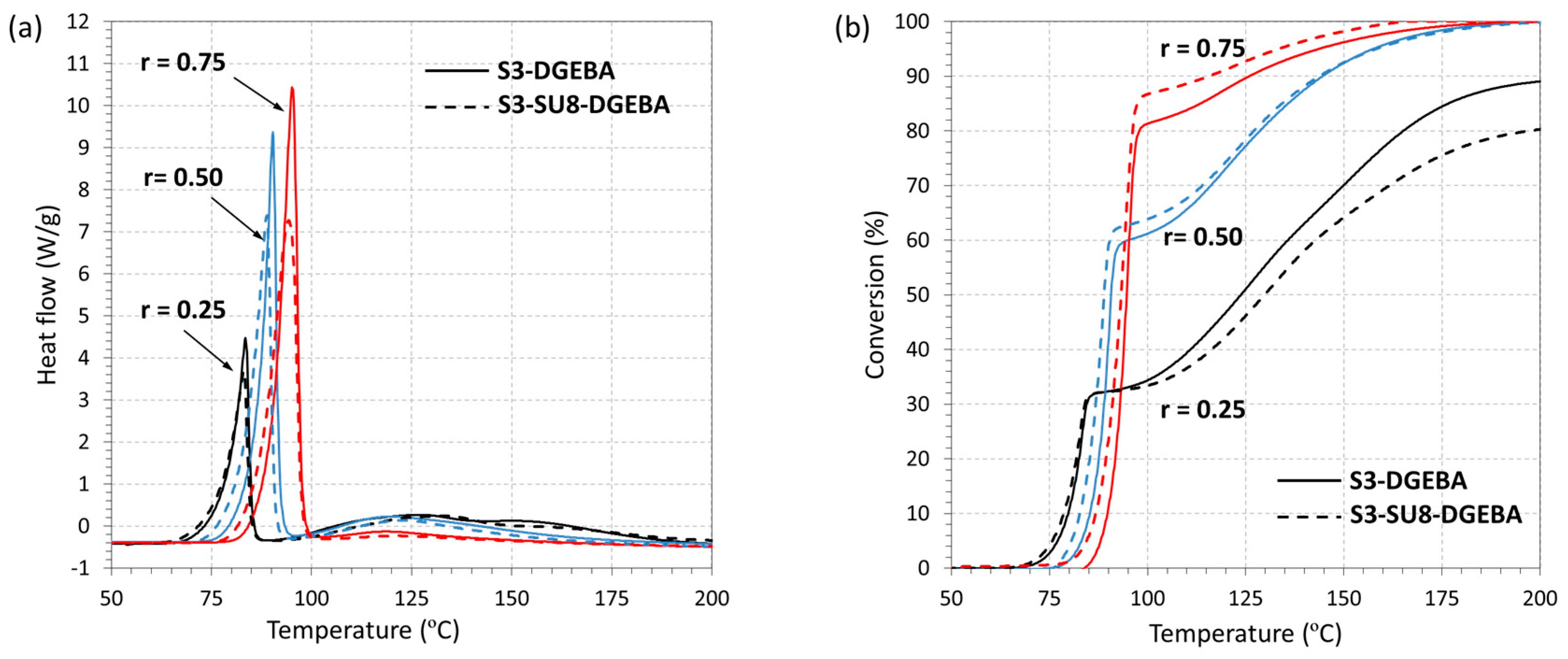
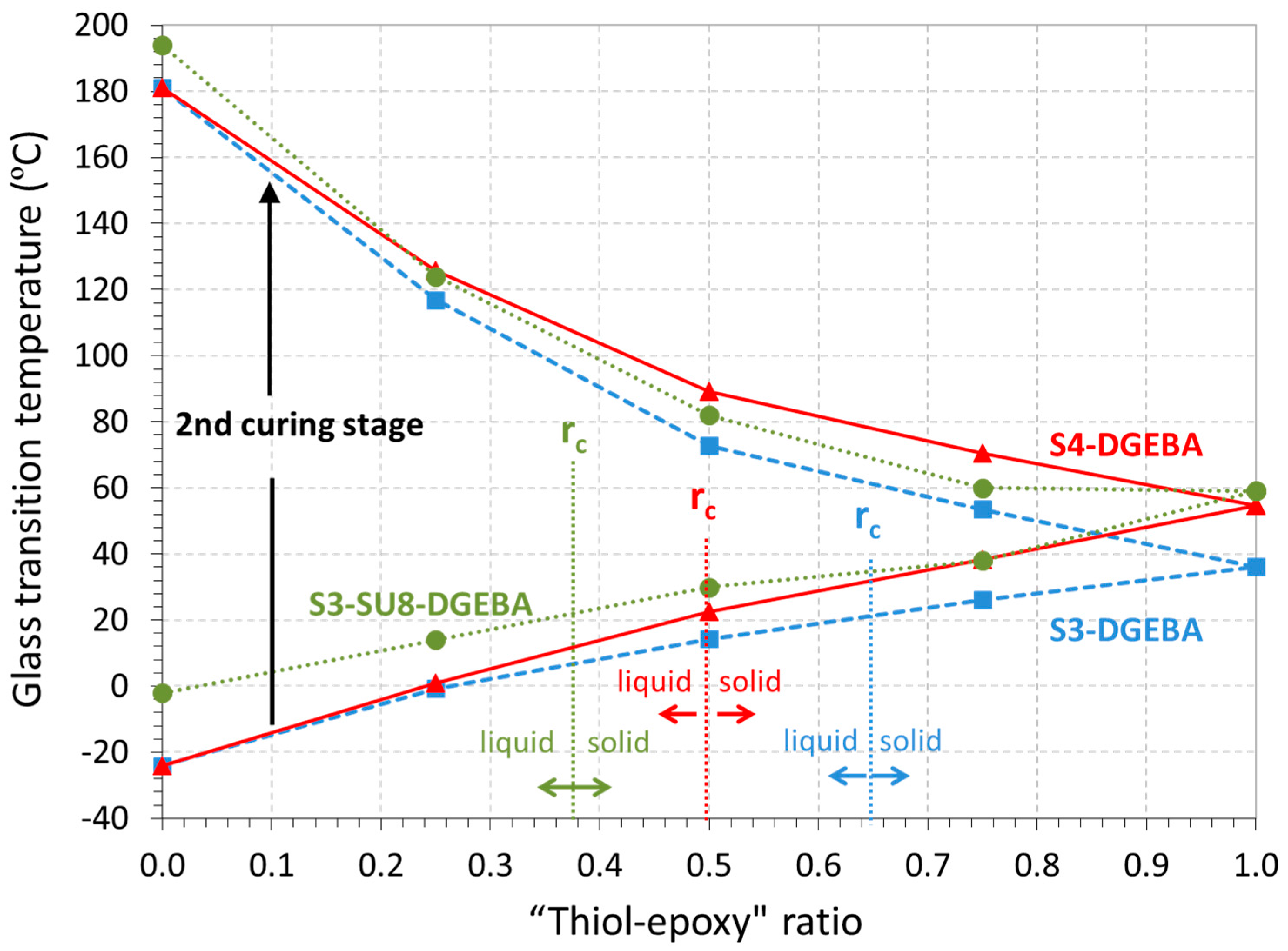
3.1. DSC Analysis of the Dual-Curing Process

As it was explained in our previous works [19,20], sequential dual-curing systems are attained by preparing different “thiol–epoxy” mixtures in off-stoichiometric proportions. The use of tertiary amines as catalyst allows the separation of both polymerization processes, the initial polycondensation between thiol and epoxy groups and the following homopolymerization of the remaining unreacted epoxy groups. The monomers and expected networks formed after the “thiol–epoxy” polycondensation (1st curing stage) and epoxy homopolymerization (2nd curing stage) are shown in Figure 5. As it can be seen, the “thiol–epoxy” click polycondensation takes places rapidly at low temperature, leading to partially-crosslinked network structures. These intermediate materials are stable at room temperature until the temperature is increased and the remaining epoxy groups react forming a highly crosslinked and less flexible network structure, enhancing the thermomechanical properties of the material.
In order to analyze the duality of the new system, the curing process of both S3-SU8-DGEBA and S3-DGEBA systems at different “thiol–epoxy” ratios are illustrated in Figure 6. In Figure 6a, the heat flow is plotted as a function of the temperature. The presence of two well-separated peaks in is an indication of two sequential polymerization processes taking place, in agreement with our previous results [20]. The first and sharper peak is related to the “click” thiol–epoxy polycondensation, while the broader and smaller peak to the anionic epoxy homopolymerization of the excess epoxy groups. Therefore, the incorporation of SU8 does not affect the duality of the curing process. In Figure 6b the conversion is plotted as a function of the temperature. Note that the conversion curves (Figure 6b) have been determined taking into account empirical values of the enthalpy of reaction from the literature: the thiol–epoxy polycondensation (1st curing process) releases around 130 kJ/eq., while the epoxy homopolymerization around 100 kJ/eq. [28,29]. Within experimental error, the contribution of the first process to the total conversion is proportional to the presence of thiol in the mixture and is not affected by the presence of SU8, as could be expected.
In Table 2, the enthalpy values corresponding to each polymerization process are presented. As can be seen, the “thiol–epoxy” polycondensation (1st curing process) releases around 130 kJ/eq., similar values to the reported one. Nevertheless, during the epoxy homopolymerization, formulations containing high content of epoxy excess (r = 0.25), do not reach the expected enthalpy value. Moreover, this is more evident in the S3-SU8-DGEBA system; the enthalpy per equivalent epoxy is 79.1 kJ/eq., while in the S3-DGEBA system is 84.4 kJ/eq., both of them lower than 100 kJ/eq. This may be caused by topological restrictions in the highly crosslinked homopolymer network, especially in the presence of SU8, leading to incomplete reaction of epoxy groups.

3.2. Thermomechanical Results

In Figure 7, the glass transition temperatures (Tg) of the intermediate materials (lower curves) and final materials (upper curves) are shown for all the systems of study at the different “thiol–epoxy” ratios (the data for S3-DGEBA and S4-DGEBA are taken from our previous work [19]). Overall, two different trends are shown for each material: the Tg of the intermediate materials increase with increasing “thiol–epoxy” ratio due to the decreasing amount of unreacted excess DGEBA at the end of the first stage of the curing process (see schemes in Figure 5). In contrast, the Tg of the final materials increases with decreasing “thiol–epoxy” ratio because of the higher contribution of the homopolymerization of the excess epoxy groups. The increase of functionality of the crosslinking agents, S3 and S4, results in somewhat different properties at high “thiol–epoxy” ratios and reduces the critical ratio, rc. In contrast, the incorporation of the high functional resin SU8 also produces an increase in Tg at lower “thiol–epoxy” ratios and also reduces significantly the critical ratio rc because of its higher functionality. The Tg of the uncured neat epoxy formulation (without thiol) increases from −23 to −1 °C when SU8 is added to the formulation, due to the lower mobility of the highly functional SU8 monomer. The final Tg of the neat epoxy homopolymer increases from 181 to 193 °C when SU8 is added. This small increase in the final Tg of the homopolymer can be explained by the fact that conversion of epoxy groups may not be complete due to topological restrictions, as explained in the preceding section. Overall, the possibility to modulate the structural properties of the materials and the critical ratio of the systems by combining different thiol and epoxy compound makes it possible to extend the processing of complex-shaped materials to lower “thiol–epoxy” ratios and therefore makes it possible to get materials with also different structural properties.
Table 3 shows the results of the thermomechanical characterization of the cured materials using DMA. In agreement with the above explanation, on decreasing the “thiol–epoxy” ratio, i.e., increasing the amount of epoxy homopolymerization, the Tg of the materials increases significantly. In the same way, the relaxed modulus, Er, increases and the relaxation process becomes more heterogeneous (FWHM increases and the peak of the tanδ curve decreases). It is well known that the increase of the crosslinking density leads to higher relaxed modulus and a more heterogeneous network structure with longer relaxation times. The incorporation of a highly functional and rigid epoxy resin (SU8) to the S3-DGEBA system has an evident impact on the structural properties, showing a noticeable increase in Er and Tg and a significant broadening of the network relaxation process, as deduced from the increase in FWHM (i.e., from 12.1 °C in the S3-DGEBA-0.75 to 22.8 °C in the S3-SU8-DGEBA-0.7) and the decrease in the tanδ peak height.
In terms of shape-memory properties, the relation Eg/Er is higher of 100 in all cases; this means two orders of magnitude, which is sufficiently high to expect good SMR in terms of shape-fixation and -recovery. This parameter increases with the decrease of Er on approaching the stoichiometric ratio because, in all these materials, the value of the glassy modulus Eg is similar regardless of the structural differences and therefore the relation is governed by Er. On the other hand, the homogeneity of the relaxation process (quantified by the breadth of tanδ) gives us an idea of the shape-recovery rate [21]. The S3-SU8-DGEBA materials have broader relaxation processes and therefore it is expected a slower and more gradual recovery-process in comparison with the other systems.

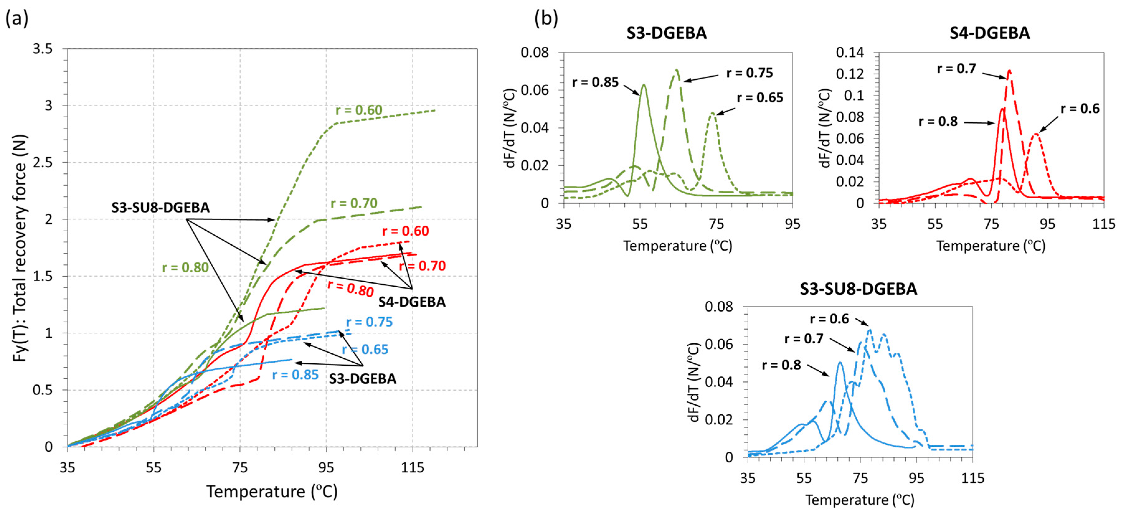
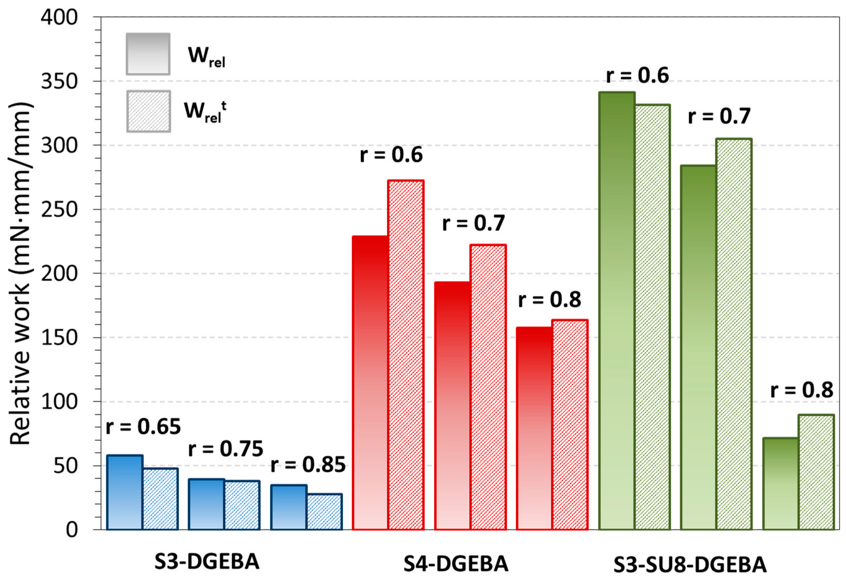
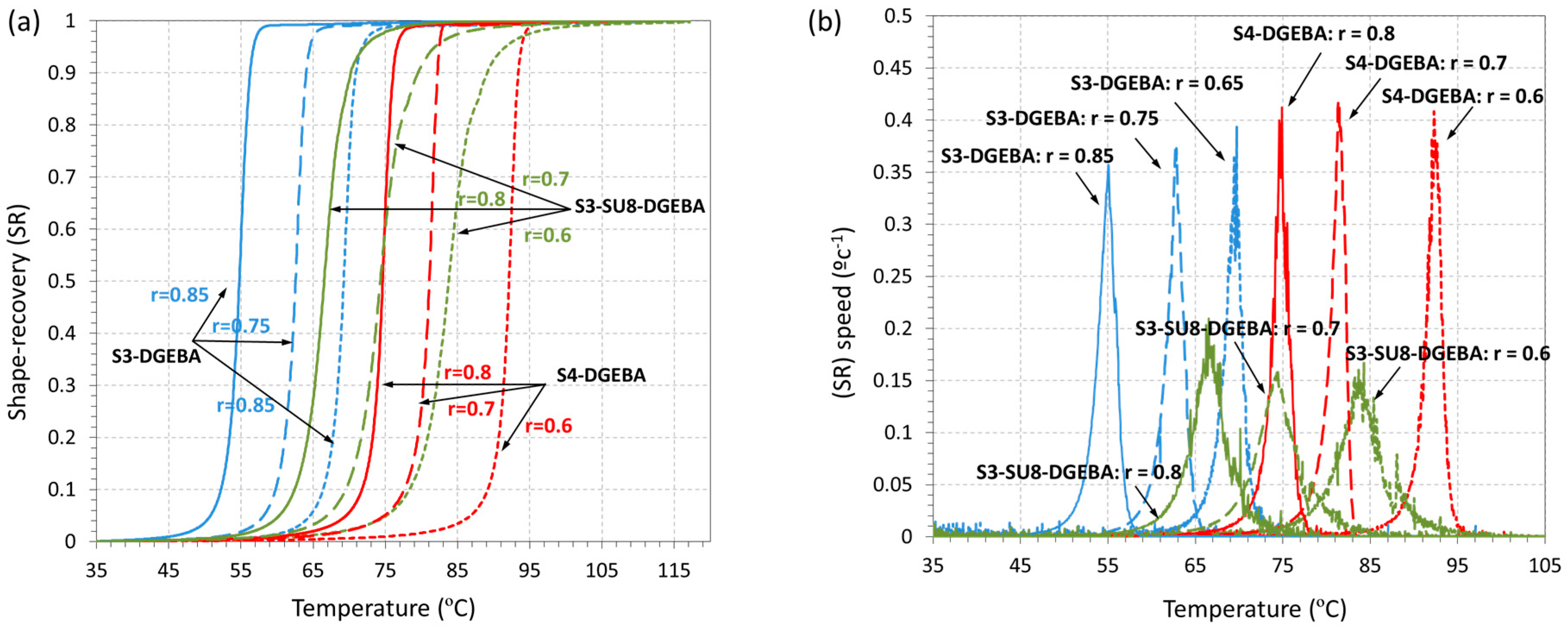
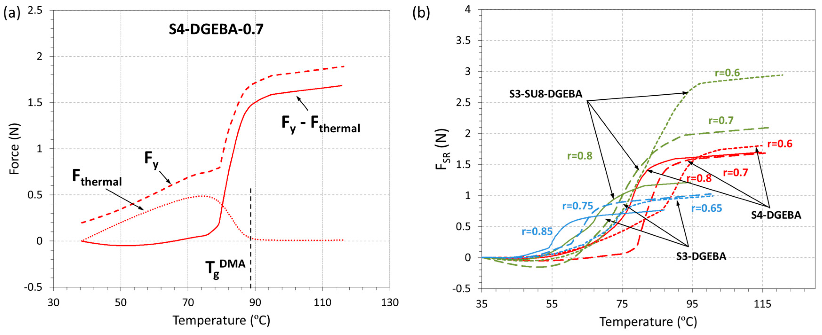
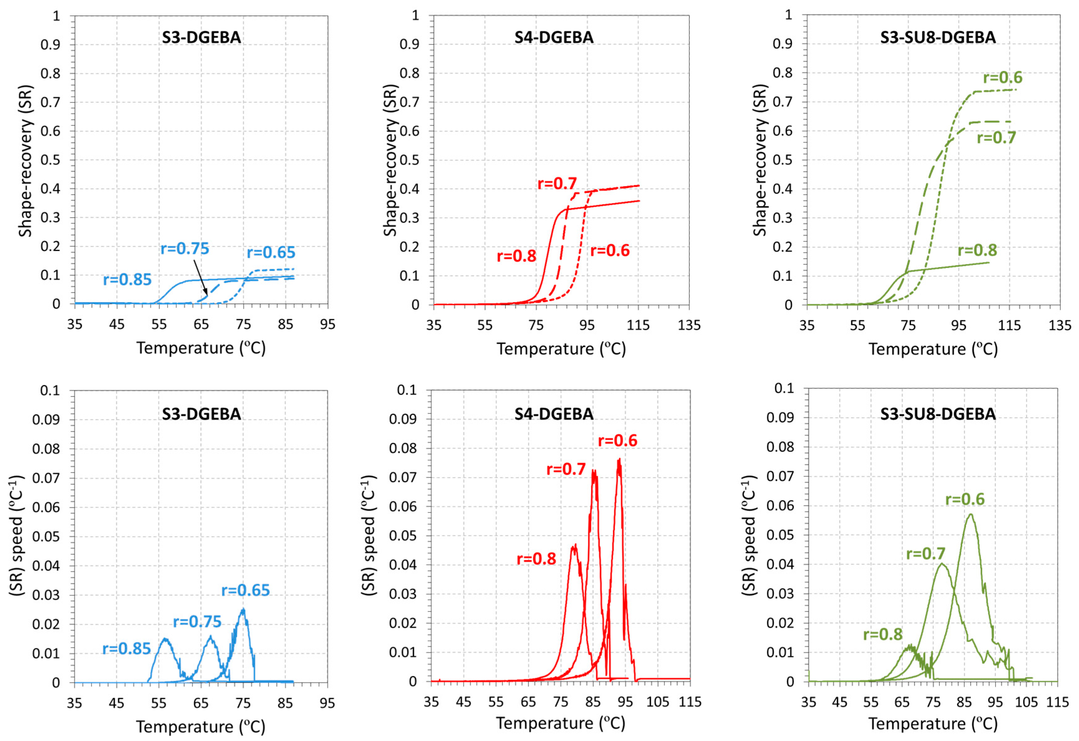
3.3. Shape-Memory Results

As stated in the experimental part, the shape-memory characterization has been studied under three different scenarios (see Figure 4). The results of the unconstrained recovery experiments are shown in Figure 8 and the parameters of interest summarized in Table 4. First, it should be pointed out that all the samples were able to completely recover the original shape, with values of Rr almost equal to 100% in all cases. This can be explained by the safe programming conditions and the structural properties of epoxy-based SMPs [16]. The programming was carried out at Tprog >> Tg and under mild deformation conditions, therefore completely elastic deformation was imposed, where no damaging processes and no stress relaxation were involved.
The evolutions of the shape-recovery (SR) and recovery speed (SRspeed) parameters show a clear difference between the formulations without and with SU8. The shape-recovery process is considerably faster and sharper in the materials without SU8, regardless of the use of S3 or S4 as crosslinking agent. The SRspeed curves of S4-DGEBA formulations are slightly taller and narrower than those of S3-DGEBA formulations, but, if one analyzes the overall recovery rate Vr (see Table 4), it can be seen that they have very similar and high values (70%–80%/min). In contrast, the presence of SU8 leads to lower and broader SRspeed curves (∆Tpeak increases from 2 °C up to 4–5 °C), and therefore lower Vr values (around 35%/min). Moreover, the effect of the “thiol–epoxy” ratio is more relevant with the presence of SU8, leading to a clear decrease in Vr from 46% to 35% on increasing the epoxy content from r = 0.8 to r = 0.6 in the S3-SU8-DGEBA system, while this is not that evident in the S3-DGEBA and S4-DGEBA systems. This must be caused by the effect of the strongly hindered homopolymer structure of SU8 in comparison with DGEBA.
Parameters as ∆Tpeak and Tpeak are closely related to the glass transition. Tpeak is commonly close to the Tg nominal value and ∆Tpeak is related to the breath of the tanδ curve. As it can be seen, in all the experiments, Tpeak is placed slightly below TgDMA: however it increases with the increase in epoxy content accordingly to the trend observed in the TgDMA. Moreover, the differences regarding ∆Tpeak are clearly related to the structural relaxation. As explained above, formulations containing SU8 show higher ∆Tpeak due to the broader relaxation process as deduced from the FWHM values in Table 2. These results point out the close relation between network relaxation and shape-recovery in glassy materials, as previously observed [22].
Fully-constrained experiments were carried out to determine the response of the material under a completely impeded scenario. The DMA was set in Iso-Strain mode and the force, Fy(T), generated by the sample during the recovery-process was recorded. The results are shown in Figure 9 and the parameters of interest summarized in Table 4. In a similar way to the SRspeed (Figure 8b), the force rate, dFy/dT, in (N/°C) has been determined and presented as small side graphics on the right side of the figure for all the formulations under study.
The recovery-process can be divided into three different sections (see Figure 9a). First, there is a constant increase of the force mostly related to the thermal expansion of the material at temperatures below Tg. Then, on approaching to Tg, the material undergoes an initial relaxation process caused by the lowering of the modulus followed by a drastic increase of the force due to the SME. This is clearly appreciated in the N/°C graphics on Figure 9b, showing an initial and small decreasing peak followed by a drastic increasing peak. Finally, the force slightly increases probably due to the thermal expansion at temperatures above Tg. The effect of the network structure is clearly appreciated in the homogeneity of the recovery-process, as deduced from the shape of the, dFy/dT, curves (Figure 9b). Formulations containing SU8 show broader and slower processes, while S3-DGEBA and S4-DGEBA systems have sharper and faster processes. Moreover, the effect of the presence of the SU8 molecule is clearly appreciated; on decreasing the ratio to 0.6 in the S3-SU8-DGEBA system, up to three peaks appear during the SME, pointing out the complex relaxation process produced by the presence of SU8 in the thiol–epoxy and epoxy homopolymer networks.
On analyzing the parameters obtained from dFy/dT, it can be seen that both, ∆Tpeak and Tpeak, are clearly related to the glass transition process and network structural properties, in accordance with the unconstrained experiments. Nevertheless, the magnitude of ∆Tpeak is considerably higher in all the formulations of study. Moreover, the differences regarding the content of SU8 are more evident in the S3-SU8-DGEBA system, ∆Tpeak increases from 7 °C at r = 0.8 to 23.9 °C at r = 0.6. This suggests that in completely impeded scenarios, differences regarding the crosslinking points are more relevant than in unconstrained experiments [30], and that, overall, the recovery-process is extended longer.
The thermal force, Fthermal(T), and its effect on Fy(T) is shown in Figure 10. In Figure 10a, Fthermal(T) is plotted as a function of the temperature and subtracted from Fy(T) to obtain the shape-recovery force, FSR(T), for the formulation S4-DGEBA-0.7, while, in Figure 10b, the FSR(T) curves are presented for all the formulations studied. As can be seen in Figure 10a, the higher contribution of Fthermal(T) takes place at T < Tg; Fthermal(T) increases until a maximum is reached, and then goes down to a minimum and almost constant value. This is caused by the drastic decrease of the modulus as the material becomes a rubber. Having in mind these results, the resulting curves FSR(T) = Fy(T) − Fthermal (Figure 10b) clearly point out that, as stated above, the thermal expansion is the responsible of the initial increase of Fy(T), while FSR(T) is mainly related to the network relaxation and build-up of stress in the fully-impeded recovery process taking place during heating. This result emphasizes the relevance of the thermal expansion in fully-constrained experiments at temperatures below Tg and should be taken into account in certain applications to avoid an early undesired actuation.
The value and evolution of FSR is closely related to the network structural properties. In general, formulations with higher relaxed modulus (see Table 2) lead to higher FSR values (SU8 > S4 > S3 see in Table 4). However, there is a clear difference in the presence of SU8, which may be connected to its molecular structure. Moreover, on decreasing the ratio in the S3-SU8-DGEBA system, i.e., increasing the epoxy homopolymer content, FSR increases much more than in the other cases.
Partially-constrained experiments were performed to fully characterize the SMR in more realistic applications since most of the SMPs are required to recover their shape working against a force. A constant force, Fw, is applied to the sample and the work done by the sample during the recovery-process is calculated. Fw is fixed to a constant value for all the experiments. As can be seen in Table 4, the minimum force to ensure that all the formulations are able to produce a positive work is 0.5 N (the S3-DGEBA-0.85 gives the minimum FSR value of 0.53 N). The shape-recovery curves (SR) and the shape-recovery instantaneous speed SRspeed are shown in Figure 11, and the parameters of interest summarized in Table 4.
First, it must be noted that all the samples were able to partially recover the original shape, that is, a positive work was produced. The shape of the (SR) curves is similar to that of the unconstrained recovery experiments, but the SRspeed curves are broader, as in fully-constrained experiments. In contrast, the influence of the crosslinking points is not evident in partially-constrained experiments. ∆Tpeak is similar or even lower in formulations with higher content of epoxy (i.e., ∆Tpeak of S3-SU8-DGEBA-0.7 is 12.1, while it goes down to 10.9 in S3-SU8-DGEBA-0.6). In general, Tpeak is closely related to TgDMA in all experimental modes, while ∆Tpeak increases from unconstrained to fully-constrained modes, pointing out an extension of the recovery-process caused by the presence of an external force impeding or making difficult the recovery of the original shape.
The experimental relative work and the theoretical relative work, Wrel, are shown in Figure 12. As mentioned in the experimental section, the work has been normalized to a relative work (mN·mm/mm) in order to allow comparison between samples taking into account the differences in the deflection. The increase in functionality of the crosslinker compound (SU8 > S4 > S3), as well as the presence of the SU8 in the network structure clearly enhance the mechanical performance of the actuator, in line with the results from the fully-constrained experiments. Wrel increases on increasing FSR, because the sample is able to produce a higher displacement of the clamp during the SME. Moreover, it is clearly appreciated an increasing trend of Wrel on decreasing the “thiol–epoxy” ratio in all the systems of study. These results point out that the increase of the crosslinker functionality (the presence of the DGEBA homopolymer) has a positive effect in the force generated during the recovery-process as shown in the fully-constrained experiments.
As stated in the experimental part, it is possible to predict the theoretical relative work, Wrelt as follows: the theoretical dy(Tend) reached by the sample during the recovery-process is approached by using Equations (6) and (7) and then Wrelt is determined by simply applying Equation (5) with the predicted dy(Tend). Through this methodology, one considers that the sample produces a FSR equal to Fprog as no energy losses takes place during the programming and thus, all the programmed force is then released during the recovery-process. In Figure 12, the comparison between the experimental relative work generated and the predicted one is presented.
As it can be observed, the use of the beam formula for small deformations gives reliable and good results; the predicted values fit very well with the experimental ones. This can be explained as follows: on one side, during the programming process, the sample is above Tg and the network structure completely relaxed, therefore, the response of the sample to the applied stress is completely elastic. On the other side, the recovery-process takes place in between and above Tg, with a constant force applied, thus, the time-scale of the experiment is high enough to allow almost complete relaxation of the network during the process. This means that the sample response is almost completely elastic to the stress applied in both, the programming and the recovery processes; therefore, the equation is able to predict properly the final deflection and/or force applied.

4. Conclusions

Bent-shaped shape-memory actuators have been successfully characterized by taking advantage of the sequential dual-curing of off-stoichiometric “thiol–epoxy” mixtures. By appropriately choosing the “thiol–epoxy” ratio, solid-like and conformable materials are formed after the first curing stage that can be easily processed into bent-shaped materials and fixed thanks to the crosslinks formed in the second curing stage. The SMPs have been fully characterized as potential actuators in different shape-memory scenarios: unconstrained, partially-constrained and fully-constrained. The unconstrained recovery experiments showed an efficient and tailorable recovery process; the SMPs are able to efficiently fix the temporary-shape and completely recover their original shape with high recovery rates. The dependence of the recovery-process on the network structure, in particular on the network relaxation process, has been clearly evidenced in the presence of the high functional epoxy resin SU8 in the S3-DGEBA system, leading to more heterogeneous network structures and thus lower recovery rates.
The fully-constrained experiments showed the capability of these materials to release a force instead of recovering the original shape on heating above Tg. This force has been found closely related to the network structure and chemical structure of the crosslinking points. The presence of crosslinks of higher functionality increase the force released during the SME. Moreover, large and spatially impeded crosslinks (SU8 molecule) produce a major effect on the force enhancement.
In partially-constrained experiments, the materials showed the capability to produce a positive work on heating above Tg. The work released shows an increasing trend with the increase of the crosslinks functionality and size (SU8 > S4 > S3), as well as with the increase of epoxy excess accordingly to the force released in the fully-constrained experiments. Moreover, it has been shown that it is possible to efficiently predict the work released by applying the beam deflection formula for small flexural deformations only taking into account the relaxed modulus and dimensions of the sample.
In general, the recovery-process is closely related to the network structure and its relaxation process in all experimental setup. The temperature at which the maximum rate is found (Tpeak) is closely related to the Tg nominal value, while the heterogeneity of the relaxation process is connected with the length or duration of the recovery-process, which depends on the experimental setup and increases according to the constraint level, from unconstrained to fully-constrained experiments.

Acknowledgments

The authors would like to thank MICINN (MAT2014-53706-C03-01 and MAT2014-53706-C03-02) and Generalitat de Catalunya (2014-SGR-67) for financial support. Xavier F.-F. also acknowledges the Serra-Húnter program from the Generalitat de Catalunya.

Author Contributions

Silvia De la Flor, Xavier Fernández-Francos, Veronica Ambrogi and Alberto Belmonte conceived and designed the experiments, which were performed and analyzed by Alberto Belmonte and Claudio Russo. Alberto Belmonte wrote the paper. Silvia De la Flor, Xavier Fernández-Francos and Veronica Ambrogi revised the paper.

Conflicts of Interest

The authors declare no conflict of interest.

References

  1. Hager, M.D.; Bode, S.; Weber, C.; Schubert, U.S. Shape memory polymers: Past, present and future developments. Prog. Polym. Sci. 2015, 49–50, 3–33. [Google Scholar] [CrossRef]
  2. Lendlein, A.; Sauter, T. Shape-memory effect in polymers. Macromol. Chem. Phys. 2013, 214, 1175–1177. [Google Scholar] [CrossRef]
  3. Wu, X.; Huang, W.M.; Zhao, Y.; Ding, Z.; Tang, C.; Zhang, J. Mechanisms of the shape memory effect in polymeric materials. Polymers 2013, 5, 1169–1202. [Google Scholar] [CrossRef]
  4. Li, G.; Wang, A. Cold, warm, and hot programming of shape memory polymers. J. Polym. Sci. Part B Polym. Phys. 2016, 54, 1319–1339. [Google Scholar] [CrossRef]
  5. Arrieta, S.; Diani, J.; Gilormini, P. Experimental characterization and thermoviscoelastic modeling of strain and stress recoveries of an amorphous polymer network. Mech. Mater. 2014, 68, 95–103. [Google Scholar] [CrossRef] [Green Version]
  6. Xiao, R.; Guo, J.; Nguyen, T.D. Modeling the multiple shape memory effect and temperature memory effect in amorphous polymers. RSC Adv. 2015, 5, 416–423. [Google Scholar] [CrossRef]
  7. Lewis, C.L.; Meng, Y.; Anthamatten, M. Well-Defined Shape-Memory Networks with High Elastic Energy Capacity. Macromolecules 2015, 48, 4918–4926. [Google Scholar] [CrossRef]
  8. Zhao, Q.; Qi, H.J.; Xie, T. Recent progress in shape memory polymer: New behavior, enabling materials, and mechanistic understanding. Prog. Polym. Sci. 2015, 49–50, 1–42. [Google Scholar] [CrossRef]
  9. Xiao, X.; Kong, D.; Qiu, X.; Zhang, W.; Zhang, F.; Liu, L.; Liu, Y.; Zhang, S.; Hu, Y.; Leng, J. Shape-Memory Polymers with Adjustable High Glass Transition Temperatures. Macromolecules 2015, 48, 3582–3589. [Google Scholar] [CrossRef]
  10. Zhou, J.; Sheiko, S.S. Reversible shape-shifting in polymeric materials. J. Polym. Sci. Part B Polym. Phys. 2016, 1, 1–16. [Google Scholar] [CrossRef]
  11. Lewis, C.L.; Dell, E.M. A Review of Shape Memory Polymers Bearing Reversible Binding Groups. J. Polym. Sci. Part B Polym. Phys. 2016, 1340–1364. [Google Scholar] [CrossRef]
  12. Tandon, G.P.; McClung, A.J.; Baur, J.W. Shape-Memory Polymers for Aerospace Applications; DEStech Publications: Lancaster, PA, USA, 2015; p. 658. [Google Scholar]
  13. Leng, J.; Yu, K.; Sun, J.; Liu, Y. Deployable morphing structure based on shape memory polymer. Aircr. Eng. Aerosp. Technol. 2015, 87, 218–223. [Google Scholar] [CrossRef]
  14. Boyle, M.A.; Martin, C.J.; Neuner, J.D. Epoxy Resins. In ASM Handbook Volume 21, Composites (ASM International); Miracle, D.B., Donaldson, S.L., Eds.; ASM International: Novelty, OH, USA, 2001; pp. 78–89. [Google Scholar]
  15. Santhosh Kumar, K.S.; Biju, R.; Reghunadhan Nair, C.P. Progress in shape memory epoxy resins. React. Funct. Polym. 2013, 73, 421–430. [Google Scholar] [CrossRef]
  16. Zheng, N.; Fang, G.; Cao, Z.; Zhao, Q.; Xie, T. High strain epoxy shape memory polymer. Polym. Chem. 2015, 6, 3046–3053. [Google Scholar] [CrossRef]
  17. Altuna, F.I.; Hoppe, C.E.; Williams, R.J.J. Shape memory epoxy vitrimers based on DGEBA crosslinked with dicarboxylic acids and their blends with citric acid. RSC Adv. 2016, 6, 88647–88655. [Google Scholar] [CrossRef]
  18. Pei, Z.; Yang, Y.; Chen, Q.; Wei, Y.; Ji, Y. Regional Shape Control of Strategically Assembled Multishape Memory Vitrimers. Adv. Mater. 2016, 28, 156–160. [Google Scholar] [CrossRef] [PubMed]
  19. Belmonte, A.; Fernández-francos, X.; Serra, À.; De la Flor, S. Phenomenological characterization of sequential dual-curing of off-stoichiometric “thiol-epoxy” systems: Towards applicability. Mater. Des. 2017, 113, 116–127. [Google Scholar] [CrossRef]
  20. Fernández-Francos, X.; Konuray, A.-O.; Belmonte, A.; De la Flor, S.; Serra, À.; Ramis, X. Sequential curing of off-stoichiometric thiol–epoxy thermosets with a custom-tailored structure. Polym. Chem. 2016, 7, 2280–2290. [Google Scholar] [CrossRef] [Green Version]
  21. Belmonte, A.; Guzmán, D.; Fernández-francos, X.; De la Flor, S. Effect of the Network Structure and Programming Temperature on the Shape-Memory Response of Thiol-Epoxy “Click” Systems. Polymers 2015, 7, 2146–2164. [Google Scholar] [CrossRef] [Green Version]
  22. Belmonte, A.; Fernández-Francos, X.; De la Flor, S. New understanding of the shape-memory response in thiol-epoxy click systems: Towards controlling the recovery process. J. Mater. Sci. 2017, 52, 1625–1638. [Google Scholar] [CrossRef]
  23. Belmonte, A.; Fernández-Francos, X.; De la Flor, S.; Serra, À. Network structure dependence on unconstrained isothermal-recovery processes for shape-memory thiol-epoxy “click” systems. Mech. Time-Depend. Mater. 2016, 1–17. [Google Scholar] [CrossRef]
  24. Santiago, D.; Fabregat-Sanjuan, A.; Ferrando, F.; De la Flor, S. Recovery stress and work output in hyperbranched poly(ethyleneimine)-modified shape-memory epoxy polymers. J. Polym. Sci. Part B Polym. Phys. 2016, 54, 1002–1013. [Google Scholar] [CrossRef]
  25. Souri, M.; Lu, Y.C.; Erol, A.; Pulla, S.S.; Karaca, H.E. Characterization of unconstraint and constraint shape recoveries of an epoxy based shape memory polymer. Polym. Test. 2015, 41, 231–238. [Google Scholar] [CrossRef]
  26. Wang, A.; Li, G. Stress memory of a thermoset shape memory polymer. J. Appl. Polym. Sci. 2015, 132, 42112–42123. [Google Scholar] [CrossRef]
  27. Pascault, J.-P.; Sautereau, H.; Verdu, J.; Williams, R.J.J. Thermosetting Polymers; CRC Press: Boca Raton, FL, USA, 2002; p. 496. [Google Scholar]
  28. Fernández-Francos, X.; Salla, J.M.; Mantecón, A.; Serra, À.; Ramis, X. Crosslinking of mixtures of DGEBA with 1,6-dioxaspiro[4,4]nonan-2,7-dione initiated by tertiary amines. I. Study of the reaction and kinetic analysis. J. Appl. Polym. Sci. 2008, 109, 2304–2315. [Google Scholar]
  29. Fernandez-Francos, X.; Cook, W.D.; Serra, A.; Ramis, X.; Liang, G.G.; Salla, J.M. Crosslinking of mixtures of DGEBA with 1,6-dioxaspiro[4,4]nonan-2,7-dione initiated by tertiary amines. Part IV. Effect of hydroxyl groups on initiation and curing kinetics. Polymer 2010, 51, 26–34. [Google Scholar] [CrossRef]
  30. Anthamatten, M.; Roddecha, S.; Li, J. Energy storage capacity of shape-memory polymers. Macromolecules 2013, 46, 4230–4234. [Google Scholar] [CrossRef]
Figure 1. Illustration of the bent-shaped sample processing: from the initial liquid mixture to the final solid bent-shaped material.
Polymers 09 00113 g001
Figure 2. Bent-shaped sample measuring definitions and a photograph of the final sample.
Polymers 09 00113 g002
Figure 3. Illustration of the shape-memory programming process.
Polymers 09 00113 g003
Figure 4. Illustration of the DMA testing procedure including the different recovery scenarios.
Polymers 09 00113 g004
Figure 5. Monomers and expected network structures after the first and second curing stages for all the systems of study.
Polymers 09 00113 g005
Figure 6. DSC traces of the curing process of the S3-SU8-DGEBA and S3-DGEBA systems at different “thiol–epoxy” ratios: (a) heat flow trace; and (b) conversion trace.
Polymers 09 00113 g006
Figure 7. Glass transition temperatures and critical ratio for the different systems of study at different “Thiol–epoxy” ratios.
Polymers 09 00113 g007
Figure 8. Shape-memory unconstrained recovery experiments: (a) shape-recovery as function of temperature; and (b) derivative of shape-recovery with respect to temperature (SRspeed) as function of temperature.
Polymers 09 00113 g008
Figure 9. Shape-memory fully-constrained recovery experiments: (a) force generated as a function of the temperature; and (b) derivative of the force generated with respect to the temperature as a function of the temperature.
Polymers 09 00113 g009
Figure 10. Shape-memory fully-constrained recovery experiments: (a) thermal force subtraction process; (b) force generated after subtracting the thermal contribution.
Polymers 09 00113 g010
Figure 11. Shape-memory partially-constrained recovery experiments: shape-recovery as a function of the temperature.
Polymers 09 00113 g011
Figure 12. Comparison between predicted Wrelt and experimental Wrel for all the formulations of study.
Polymers 09 00113 g012
Table 1. Composition of the different formulations of study.
SystemCritical ratio (rc) 1“Thiol–Epoxy” ratioThiol (wt %)DGEBA (wt %)SU8 (wt %)1MI (wt %)
S3-DGEBA0.650.6531.8667.15-0.99
0.7535.0363.98-0.99
0.8537.9161.10-0.99
S4-DGEBA0.50.6028.4370.58-0.99
0.7031.6567.36-0.99
0.8034.5964.42-0.99
S3-SU8-DGEBA0.380.6029.1446.5823.580.99
0.7032.4244.4222.490.99
0.8035.4242.4521.490.99
1 Experimentally determined from rheological analysis.
Table 2. Reaction heat of the first and second polymerization processes corresponding to the curing of S3-DGEBA and S3-SU8-DGEBA formulations with a thiol: epoxy ratios of 0.25, 0.50 and 0.75.
FormulationH1st (J/g)H2nd (J/g)H1st (kJ/eq.) 1H2nd (kJ/eq.) 1
S3-DGEBA-0.25151291131.684.4
S3-DGEBA-0.50263197132.098.7
S3-DGEBA-0.7534882131.993.2
S3-SU8-DGEBA-0.25147261133.879.1
S3-SU8-DGEBA-0.50257190134.299.1
S3-SU8-DGEBA-0.7534783136.397.8
1 Heat flow per equivalent epoxy (MWeq-epoxy determined as an average value taking into account the DGEBA:SU8 proportion).
Table 3. Thermomechanical and structural properties of the different formulations of study.
FormulationS3-DGEBAS4-DGEBAS3-SU8-DGEBA
“thiol–epoxy” ratio0.650.750.850.60.70.80.60.70.8
Eg (MPa)215020012130220021302150231022502310
Er (MPa)10.99.68.418.415.114.019.517.314.4
TgDMA (°C)80.170.061.098.089.081.096.081.073.0
FWHM (°C)12.812.111.011.510.510.023.022.821.8
tanδ peak1.251.351.461.161.231.300.690.810.92
Eg/Er197208254120141154118130160
Table 4. Parameters obtained from the shape-memory analysis (unconstrained, partially-constrained and fully-constrained) of the different formulations studied: Peak temperature (Tpeak), Width at half-height of the peak (Tpeak), Recovery-rate (Rr), Relative Work output (Wrel) and shape-recovery force (FSR).
UnconstrainedPartially-constrainedFully-constrained
FormulationRr (%)Tpeak (°C)Tpeak (°C)Vr (%/min)Tpeak (°C)Tpeak (°C)Wrel (mN·mm/mm)Tpeak (°C)Tpeak (°C)FSR (N)
S3-DGEBA-0.6599.92.069.773.74.075.0575.074.00.74
S3-DGEBA-0.75100.02.062.976.74.767.2396.264.50.76
S3-DGEBA-0.8599.52.355.080.35.256.7345.456.20.53
S4-DGEBA-0.6099.91.792.379.23.793.21877.691.01.71
S4-DGEBA-0.7099.91.881.372.14.385.71796.781.81.42
S4-DGEBA-0.8099.81.874.979.06.279.61365.678.41.47
S3-SU8-DGEBA-0.6099.84.984.334.710.987.231423.981.92.92
S3-SU8-DGEBA-0.7099.84.874.437.712.177.724712.477.81.79
S3-SU8-DGEBA-0.8099.94.166.545.87.867.9497.068.30.89

