Article

Performance of a Novel Fertilizer-Drawn Forward Osmosis Aerobic Membrane Bioreactor (FDFO-MBR): Mitigating Salinity Build-Up by Integrating Microfiltration

1
Centre for Technology in Water and Wastewater (CTWW), School of Civil and Environmental Engineering, University of Technology Sydney (UTS), P.O. Box 123, 15 Broadway, Ultimo NSW 2007, Australia
2
College of Environmental Science and Engineering, State Environmental Protection Engineering Center for Pollution Treatment and Control in Textile Industry, Donghua University, Shanghai 201620, China
3
School of Civil, Environmental and Architectural Engineering, Korea University, 1-5 Ga, Anam-Dong, Seongbuk-Gu, Seoul 136-713, Korea
*
Author to whom correspondence should be addressed.
Water 2017, 9(1), 21; https://doi.org/10.3390/w9010021
Submission received: 4 October 2016 / Revised: 14 December 2016 / Accepted: 15 December 2016 / Published: 4 January 2017
(This article belongs to the Special Issue Advanced Membranes for Water Treatment)

Abstract

:
In this paper, three different fertilizer draw solutions were tested in a novel forward osmosis-microfiltration aerobic membrane bioreactor (MF-FDFO-MBR) hybrid system and their performance were evaluated in terms of water flux and reverse salt diffusion. Results were also compared with a standard solution. Results showed that ammonium sulfate is the most suitable fertilizer for this hybrid system since it has a relatively high water flux (6.85 LMH) with a comparatively low reverse salt flux (3.02 gMH). The performance of the process was also studied by investigating different process parameters: draw solution concentration, FO draw solution flow rate and MF imposed flux. It was found that the optimal conditions for this hybrid system were: draw solution concentration of 1 M, FO draw solution flow rate of 200 mL/min and MF imposed flux of 10 LMH. The salt accumulation increased from 834 to 5400 μS/cm during the first four weeks but after integrating MF, the salinity dropped significantly from 5400 to 1100 μS/cm suggesting that MF is efficient in mitigating the salinity build up inside the reactor. This study demonstrated that the integration of the MF membrane could effectively control the salinity and enhance the stable FO flux in the OMBR.

1. Introduction

Diminishing fresh water supplies due to the impacts of global warming, rapid industrialization and urbanization have prompted increased interest in indirect and direct potable reuse of impaired water [1]. This is especially an urgency for irrigation agriculture, a major consumer of water (i.e., about 70% of freshwater is consumed by this sector) [2,3]. Conventional activated sludge processes have been widely used for many years to reclaim water for non-potable use [4,5,6,7]. For potable reuse, a multiple-barrier treatment approach is required in order to protect public health. Recently, the membrane bioreactor (MBR) combining the forward osmosis (FO) process (OMBR) has attracted growing interests in the field of wastewater treatment and reclamation. In fact, compared to conventional MBR, the OMBR process has a lower fouling tendency due to the osmotic driving force instead of hydraulic pressure [8,9,10]. Besides, MBR effluent still contains a number of viruses, ions, and trace organic compounds (TOrCs) which can potentially result in risks to human beings and the environment [11,12]. The high rejection of FO membrane can therefore provide a better rejection of contaminants and retain a significant portion of suspended solids; which is another advantage of this OMBR system compared to the conventional ones. However, OMBR also has some limitations such as salinity build-up (i.e., accumulation of dissolved salts inside the bioreactor), internal concentration polarization and the energy associated with the draw solution recovery process [13,14,15]. This is due to the combination of high rejection of FO membrane which rejects the salts already present in the bioreactor and those coming from the wastewater feed solution and the reverse transport of salt from the draw solution to the bioreactor passing through the FO membrane [16,17].
The selection of an optimal draw solution is therefore critical to the OMBR process. The first criterion is that the draw solution should have a high osmotic pressure, higher than the feed solution to produce high water flux [18]. NaCl is widely used as draw solution in the FO process due to its high solubility and low toxicity at low concentrations, and it is also relatively easy to reconcentrate using conventional desalination process [13]. However, the energy associated with the DS recovery process remains high, hindering the development of the FO process and limiting its commercial application. In fact, most hybrid FO processes (e.g., FO-RO hybrid system) cannot compete with conventional water and wastewater treatment. Recently fertilizer-drawn forward osmosis (FDFO) has attracted increased interest since the diluted draw solution can be used directly for irrigation purpose as it contains the essential nutrients for plant growth and no recovery process is therefore required [19,20,21,22].
In this study, a novel hybrid system has been proposed in which the osmotic dilution of fertilizer via domestic wastewater reuse is achieved for greenhouse hydroponic application. This hybrid system consists of an osmotic membrane bioreactor for wastewater treatment combined with a side-stream microfiltration (MF) unit in order to recover treated wastewater from the aerobic sludge. Besides, MF can also help in mitigating the salinity build-up in the bioreactor. The FO process uses fertilizers as draw solution and the membrane is submerged in the bioreactor. Water is therefore drawn from wastewater and the diluted fertilizers can be used for agriculture application.
The main objective of this study was to determine a suitable fertilizer as draw solution in the novel MF-FDFO-MBR hybrid system for simultaneous wastewater treatment and greenhouse hydroponic application. The performance of the optimum DS was then studied by investigating different process parameters: draw solution concentration, flow rate, and imposed MF water flux. Moreover, salt accumulation and TOC removal efficiency in the MF-FDFO-MBR were compared to the FDFO-MBR system to investigate the performance of MF in mitigating salt accumulation inside the bioreactor.

2. Materials and Methods

2.1. Experimental Set-Up

Figure 1 shows the lab-scale submerged OMBR system with a side-stream MF membrane used in this study. The active volume of the bioreactor is 10 L and is made of acrylic plastic. The FO membrane used in the experiments was provided by Hydration Technology Innovation (Albany, OR, USA) and its characteristics have been reported in other studies [10,23]. This membrane is made of cellulose-based polymers with an embedded polyester mesh for mechanical strength with an effective membrane area of 0.024 m2. The membrane orientation was active layer facing the synthetic wastewater feed solution (i.e., AL-FS) to prevent the aggravated fouling, especially pore-clogging in the support layer [24]. The in-house fabricated side stream polyvinylidene difluoride-MF (PVDF-MF) membrane, having an effective area of 0.0754 m2, was employed for salinity control inside the reactor; the average pore size of the membrane was 0.1 μm determined by capillary flow porometry (CFP-1200-AEXL). Variable speed peristaltic pumps (Cole-Parmer, Vernon Hills, IL, USA) were used to provide variable flow rates. The MF permeate was pumped out using a peristaltic pump at a constant flux. The synthetic wastewater was continuously pumped into the bioreactor, the influent was controlled by a float water level sensor (Stefani, Welshpool, WA, Australia) to maintain a constant water level, and the oxygen was provided through an aeration diffuser (Aqua One, Sydney, NSW, Australia). The membrane was physically cleaned by scrubbing the foulant on the membrane surface using sponge balls made of polyurethane (Chux® non, Padstow, NSW, Australia).

2.2. Chemicals and Operation Conditions

Three chemical fertilizers ammonium sulphate (SOA), mono-ammonium phosphate (MAP) and potassium phosphate monobasic (KH2PO4) used in this study were reagent grade (Sigma Aldrich, Castle Hill, NSW, Australia) and were prepared by dissolving fertilizer chemicals in deionized (DI) water. Osmotic pressure and diffusivity were obtained by OLI Stream Analyzer 3.2 (OLI System Inc., Morris Plains, NJ, USA).
Initially, the reactor was seeded with 4 L sludge obtained from a domestic sewage treatment plant (Central Park Facility, Sydney, NSW, Australia). After seeding, the bioreactor was continuously fed with a synthetic municipal wastewater consisting of glucose, starch and peptone as an organic carbon source and mineral salts containing nitrogen and phosphorus as source of nutrients in the ratio of COD:N:P ratio equal to 450:40:10 with an organic load of 0.25 kg COD/m3/day, the detail characteristics are given in Table 1. This ratio is sufficient to avoid any storage of nutrients necessary for cell growth [25]. The bioreactor was put in a temperature-controlled laboratory to maintain the temperature at 22 ± 0.5 °C. Continuous aeration with an intensity of 0.5 m3/h was used in order to induce a hydrodynamic shear force for membrane fouling reduction and supply sufficient oxygen for microorganisms. The mixed liquor suspended solid (MLSS) concentration was in a range of 5–6 g/L and mixed liquor volatile suspended solid (MLVSS) concentration was in a range of 4.5–4.8. The MLSS in this study was kept between 5 and 6 g/L in order to minimize the sludge accumulation and effectively controlling and reducing fouling on the membrane surface [26]. The sludge retention time (SRT) was fixed at 40 days by discharging 250 mL of sludge from the bioreactor every day. The hydraulic retention time (HRT) of the MF-OMBR varied in a range of 4.5–13.5 h during the entire operation due to the flux decline and different MF imposed flux. The pH of mixed liquor was monitored daily and kept in the range 6.5–8 which is the typical pH range for aerobic MBR operations [27,28].
Initially, the experiments were carried out to determine the optimum conditions (i.e., draw solution type, DS concentration, DS flow rate and MF permeate flux). The performance of the FO process was evaluated in a batch mode of operation where the draw solution was continuously diluted. Following this initial screening, experiments were carried out for four weeks under optimum conditions after which MF was integrated to the system to determine its impact on mitigating the salt accumulation inside the bioreactor. Experiments with MF were conducted for additional 14 days.

2.3. Analytical Methods

The weight change of draw solution tank was recorded by a digital balance (ADAM, Oxford, CT, USA) to determine the water flux. A pH and conductivity meter (HACH, Willstätterstraße, Düsseldorf, Germany) was used to measure pH in the bioreactor, conductivity measured in the draw solution was used to determine the reverse salt flux (RSF) of draw solution salts by using the concentration curves (see Figures S1–S3 in Supplementary Materials) and measured in the bioreactor was used to determine the salinity build up, SRSF is the ratio between the RSF and the water flux. A pressure transducer (Keller, Reinacherstrasse, Basel, Switzerland) with online data acquisition was used to measure outlet membrane pressure across the microfiltration (MF) membrane. At the end of the long-term experiment, samples from the bioreactor (40 mL), MF permeate (40 mL) and diluted DS (40 mL) were collected and analyzed for Total organic carbon (TOC) was measured using a TOC analyzer (Analytikjena, Konrad-Zuse-Straße, Jena, Germany). MLSS and MLVSS concentrations were quantified according to Standard Method 2540 by using glass fibre filters (PALL Supor ®-450, Pall Corporation, Port Washington, NY, USA), oven (Labec, Marrickville, NSW, Australia) and muffle furnace (Labec, Marrickville, NSW, Australia). Dissolved oxygen (DO) was measured by a DO meter (Scientrific Pty Ltd., Yamba, NSW, Australia).
In order to evaluate water flux recovery efficiency of different fertilizer draw solutions, the membranes were systematically cleaned after 4 days of continuous operations. Before starting the experiments with wastewater as feed solution, the water flux of pristine FO membranes was evaluated with 1 M NaCl as draw solution and DI water as feed (in a separate bench-scale FO setup). Then the membrane cell was placed in the bioreactor which was fed with wastewater for 4 days and fertilizers were used as draw solution. After 4 days, due to significant flux decline, the membrane cell was taken out from the bioreactor, cleaned (i.e., by using sponge balls; gently scrubbing the foulants on the membrane surface with DI water) and water flux was re-measured with the separate bench-scale FO setup using the same baseline conditions (i.e., 1 M NaCl as draw solution and DI water as feed solution). The difference between the initial water flux and the flux obtained after cleaning was used to calculate the water flux recovery as follow:
R = J w , i J w , f J w , i × 100 %  
where R is the flux recovery after membrane cleaning (%), Jw,i, is water flux of the prinstine FO membrane in the filtration cell (LMH), and Jw,f is water flux of the fouled FO membrane after physical cleaning (LMH).

2.4. Mass Balance in the OMBR-MF System

According to the FO water flux (Jw) and solute flux (Js) models presented in previous studies [30,31], the relation between Jw and JS can be expressed as follow:
J w J S = B A β R g T   ( both   A L D S   and   A L F W )
where Jw is the volumetric water flux (L·m−2·h−1 or LMH); JS is the solute flux (g·m−2·h−1 or gMH); A and B are the water permeability (LMH·bar−1) and solute permeability (LMH) of the rejection layer, respectively; β is the van’t Hoff coefficient; Rg is the universal gas constant; and T is the absolute temperature (°C). In Equation (2), the Jw/JS ratio is largely determined by the B/A ratio. This ratio can be considered as a constant for a given rejection layer and solute type at fixed temperature. In general, a lower B/A ratio (i.e., a more selective rejection layer) is preferred in order to reduce the solute reverse transport across the FO membrane.
Considering a typical submerged OMBR, the FO feed water solute concentration is identical to the solute concentration in the mixed liquor Cml (g/L). As a result, Cml can be significantly higher than the solute concentration in the influent sewage Cin and the high salt concentration in the bioreactor may adversely affect both biological activities and the FO flux performance [32]. Thus, it is important to understand the dependence among Cml, the OMBR operating parameters and the FO membrane properties. The mixed liquor salt concentration Cml can be determined as a function of time t via solute mass balance in the MF-OMBR:
V r d C m l d t = Q i n C i n + J s A m 1 Q s C m l Q m f C m l   ( solute   mass   balance )
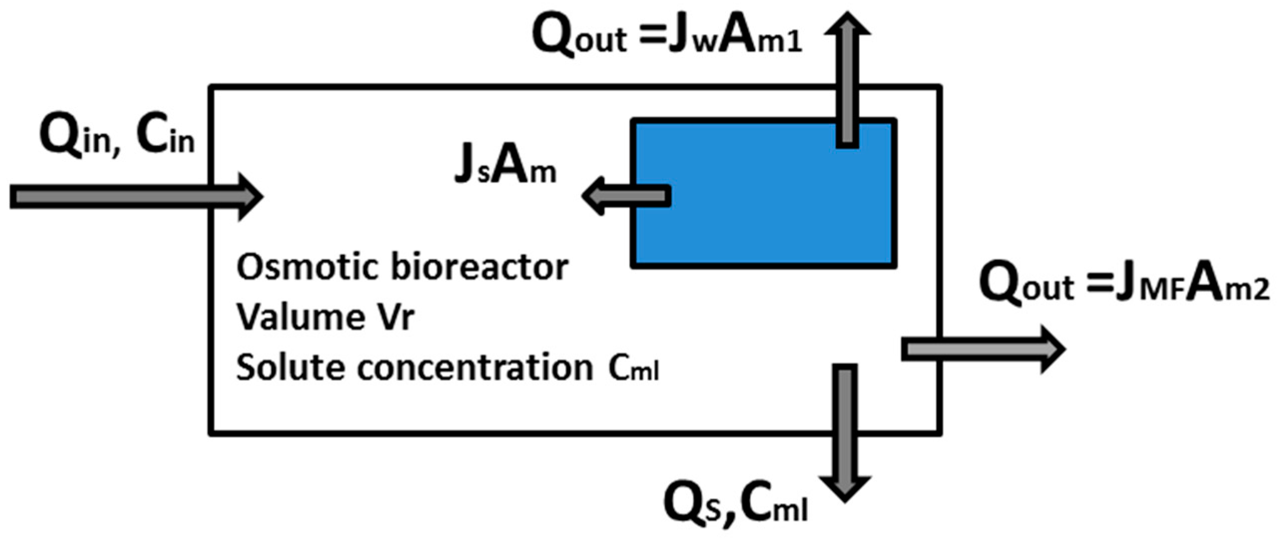
where Vr (L) is the bioreactor volume; Qin (L/h), Qs (L/h) and Qmf (L/h) are the volumetric flow of the influent sewage, the waste sludge and the MF system, respectively; and Am1 is the FO membrane area (m2). Similarly, a mass balance equation can be written for water in the OMBR:
Q i n = J w A m 1 + Q s + Q m f   ( water   mass   balance )
Substituting Equations (2) and (4), we have:
V r d C m l d t = ( J w A m 1 + Q s + Q m f ) C i n + B A β R g T J w A m 1 Q s C m l Q m f C m l
For the OMBR system shown in Figure 2, the hydraulic retention time (HRT) θHRT (h) and sludge retention time (SRT) θSRT (h) are defined respectively by:
θ H R T = V r J w A m 1 + Q s + Q m f
where
Q m f = J m f A m 2
where Jmf is the fixed MF flux (LMH) and Am2 is the MF membrane area (m2), and
θ S R T = V r Q s
Thus, Equation (5) can be re-written as:
d C m l d t = 1 θ H R T ( C i n + B A β R g T ) 1 θ S R T ( C m l + B A β R g T ) J m f A m 2 V r ( C m l + B A β R g T )

3. Results and Discussion

3.1. Process Parameters

3.1.1. Effect of Different Types of Fertilizers

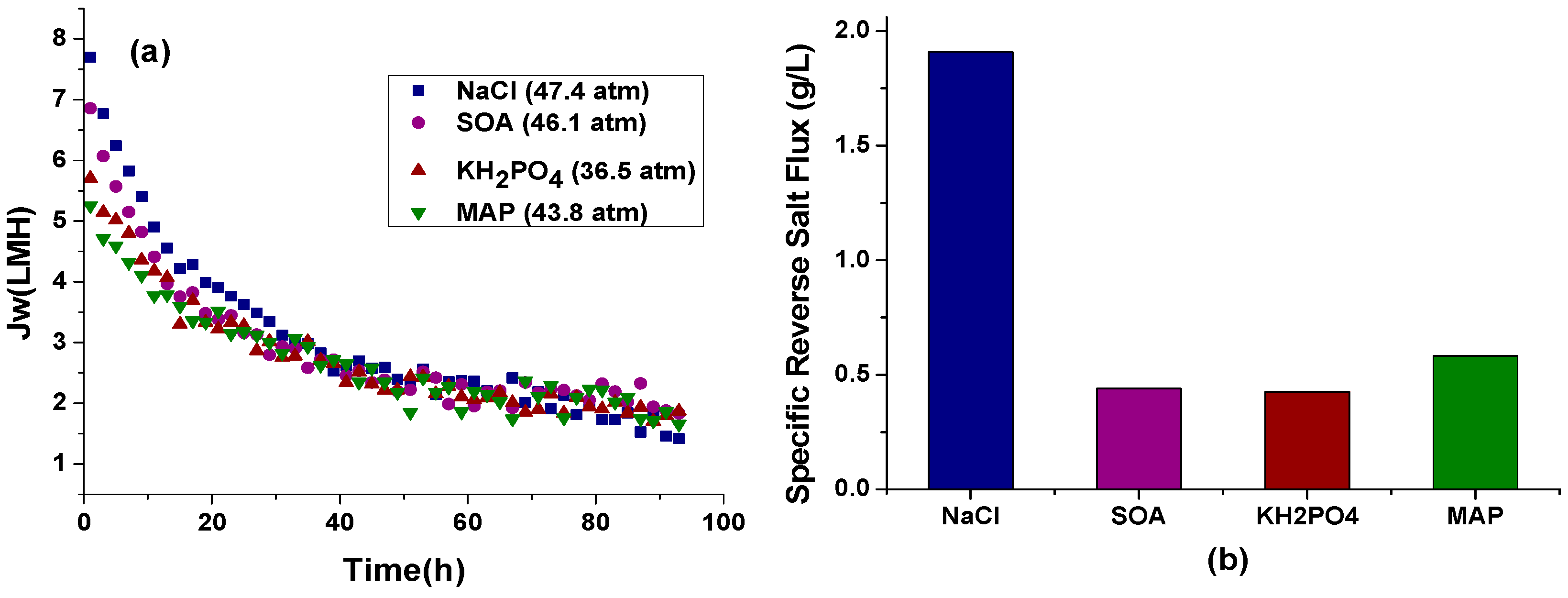
Results presented in Figure 3a show that the water flux for all the tested draw solutions significantly declined in the initial stage (up to 48 h), and then remained fairly stable at around 2–3 LMH for the next 2 days. NaCl exhibited the highest initial water flux (i.e., 7.7 LMH) followed by SOA, KH2PO4 and MAP. The flux of NaCl dropped more drastically than the other three draw solutions; which is most likely related to the higher initial flux and reverse solute flux, both contributing to the reduction of the driving force and thus the water flux. However, the theoretical osmotic pressure of the different fertilizers showed a different trend compared to the experimental water flux. In fact, MAP has a higher osmotic pressure than KH2PO4 but a lower initial water flux. This difference in water flux between fertilizers could be explained by the variations of extent of dilutive ICP which significantly affects the effective osmotic pressure difference across the membrane [33].
Since the SRSF is the ratio between the RSF and the water flux, a trade-off should be found between a sufficiently high water flux and reasonably low RSF. Results in Figure 3b show that NaCl exhibited the highest specific reverse salt flux (SRSF) (i.e., 1.91 g/L) followed by MAP, SOA, KH2PO4, which ultimately results in higher salinity build-up inside the bioreactor. This is because solute diffusion is theoretically a function of the salt rejecting properties of the membrane characterized by the salt permeability coefficient (B value) which varies with different fertilizers [34]. For instance, the low SRSF values of SOA, KH2PO4 and MAP are most likely related to their low B parameters (i.e., 0.022, 0.029 and 0.024 kg·m2·h−1, respectively). A draw solution exhibiting a lower SRSF would be the preferred option for this hybrid MF-FDFO-MBR system since the accumulation of inorganic salt ions in the bioreactor could potentially inhibit the aerobic microbial activity [14]. For that reason, SOA or KH2PO4 would be more suitable for this process.
In a previous study [35] studying a novel combined OMBR-UF hybrid system to reduce salinity build-up inside the bioreactor, the average FO water flux (using a similar HTI CTA FO membrane) and RSF were both relatively higher than the values obtained in the present study but the draw solution concentration (i.e., 26 g/L NaCl) was kept constant throughout the experiments and not osmotically diluted as it was in the present study. In another recent study focusing on wastewater reuse using a submerged FO system with commercial fertilizers as draw solutes, the reported water flux sharply decreased from 5.8 to 2.8 LMH in three days [36] which is quite similar to the results obtained here whereby the water flux decreased from 6.9 LMH to 2.5 LMH in four days using 1 M SOA as DS and similar HTI CTA FO membrane.
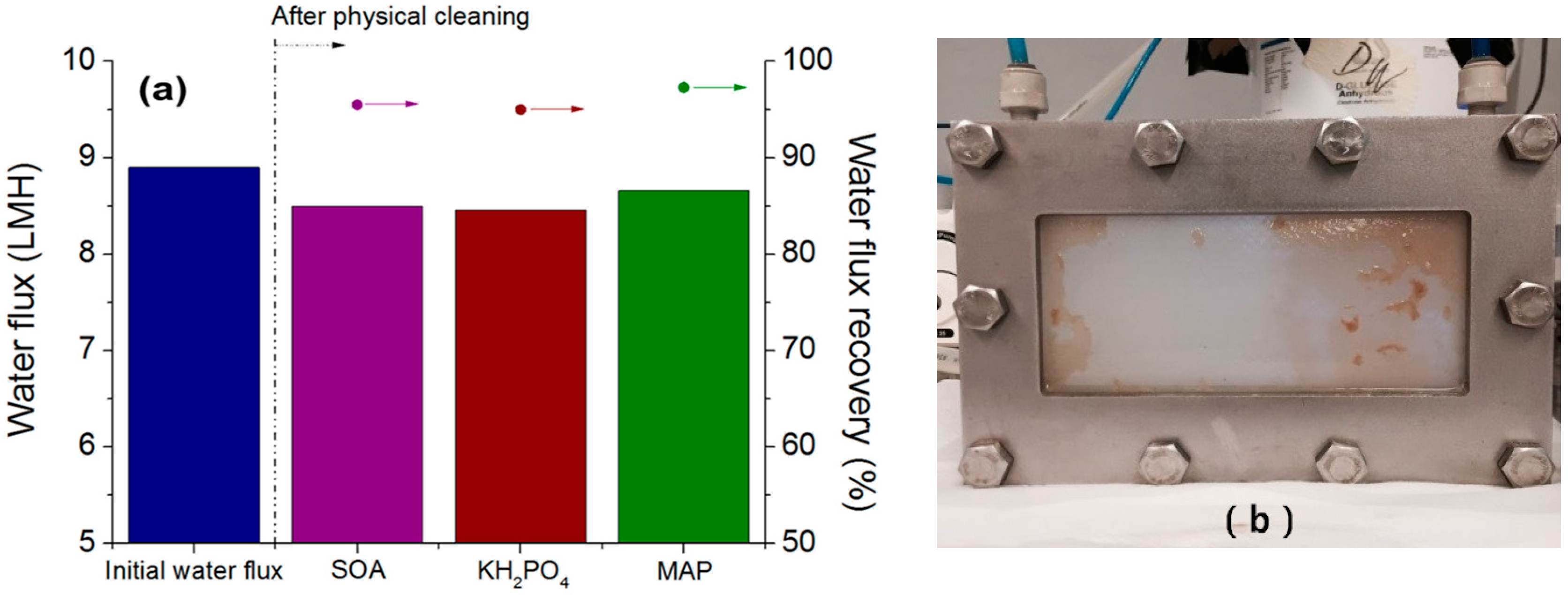
After dour-day experiments, some deposited materials were found on the membrane surface presenting a gel-like structure. This happens very typically when treating wastewater containing proteins and peptone used in this study [37,38]. The effectiveness of cleaning process was examined by measuring the water flux after cleaning. The water flux recovery was 95.5%, 95.0% and 97.2% for SOA, KH2PO4 and MAP, respectively, as shown in Figure 4a, indicating high fouling reversibility of FO [39]. Figure 4b suggests that no severe fouling occurred during four days of operation of MF-FDFO-MBR study, highlighting the low (or reversible) fouling potential of FO membrane and the effectiveness of aeration on controlling membrane fouling. In order to further mitigate membrane fouling, operation conditions such as temperature, pressure and cross-flow velocity should be optimized [40,41]. Based on water flux, SRSF value and water flux recovery data, SOA was selected as DS for further investigation and optimization of the MF-FDFO-MBR system.

3.1.2. Effect of Different DS Concentration on Water Flux and RSF

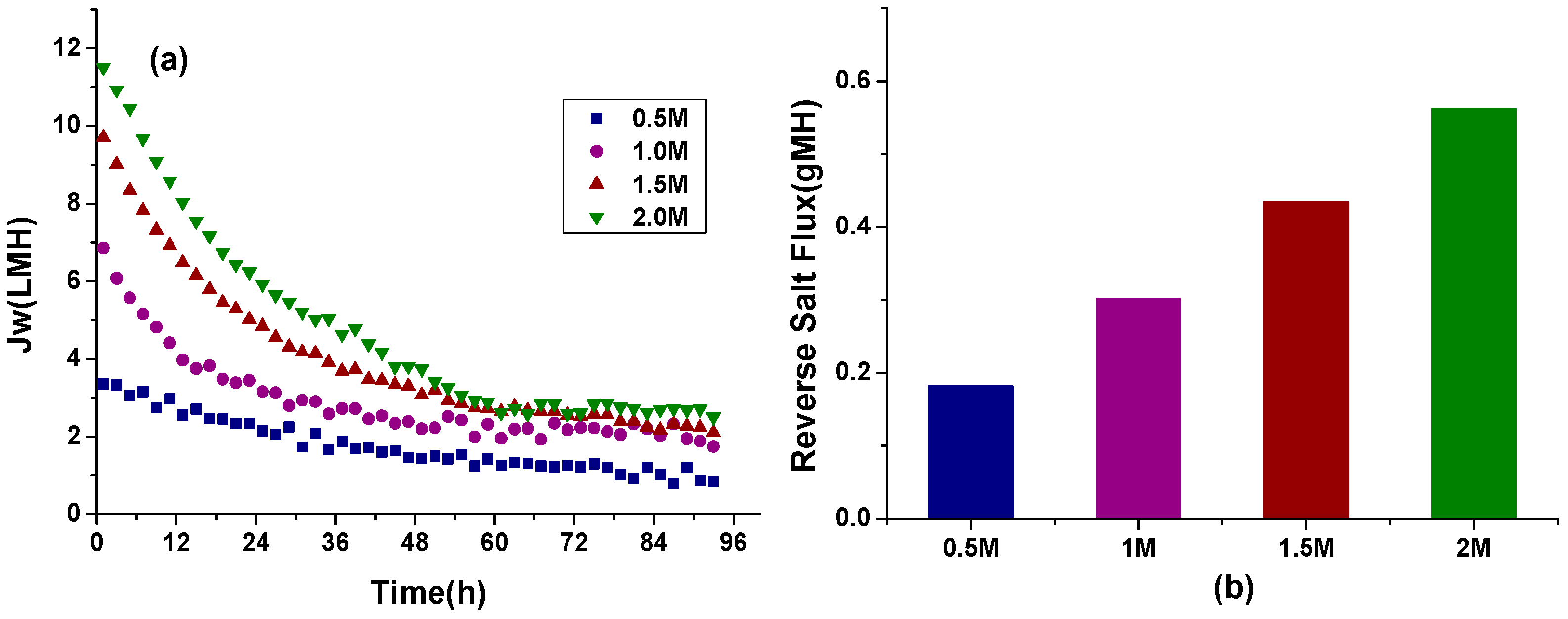
The effect of DS concentration on water flux is presented in Figure 5a. During these experiments, the DS flow rates were maintained at 200 mL/min. Results show that when operated with 2, 1.5, 1 and 0.5 M SOA draw solution (DS), high initial water fluxes of 11.5, 10, 7 and 3.4 LMH were achieved respectively. The final 3 LMH water flux for both 2 M and 1.5 M SOA DS were obtained, while, for 1 and 0.5 M SOA DS, 2.8 and 1 LMH final water fluxes were achieved, respectively.
It is clear from the results that the initial water flux increases with the increase in DS concentration. The increase in flux is attributed to an increase in osmotic pressure difference across the membrane due to the increase in the concentration of DS resulting in an increased driving force for water transport through the membrane. However, the water flux did not increase linearly with concentration; in fact, the concentration was increased four times, but the average water flux only increased by 2.7 times. This is due to the higher initial water flux enhancing the dilutive ICP which ultimately results in higher water flux decrease [42]. Moreover, the hydrodynamic properties such as density, viscosity and diffusivity are likely to be changed with concentration. The density of the DS varies slightly with concentration, whereas the diffusivity practically remains constant.
Another impact of increasing the DS concentration is the increased RSF. For optimum conditions, the RSF should be as low as possible. Thus, 1 M DS concentration was found to be the optimal concentration to operate the MF-FDFO-MBR system in this study since it can generate an acceptable water flux (i.e., about 7 LMH) and reasonable reverse salt flux (i.e., about 0.3 gMH) as shown in Figure 5b.

3.1.3. Effect of Different DS Flow Rates on Water Flux and RSF

The effect of DS flow rates on water flux and RSF is shown in Figure 6a. The initial draw solution concentration was fixed at 1 M. Increasing the flow rates should normally result in a positive impact on transfer coefficients: for the average water flux, the higher the flow rate, the higher the water flux. With an increase in flow rate from 100 to 400 mL/min, the average water flux was found to increase slightly from 2.91 to 3.18 LMH. This could be attributed to the reduction in hydrodynamic boundary layer thickness with an increase in Reynolds number (i.e., flow rate), which in turn increased the water flux [43]. However, the difference is not significant and the trend in water flux is almost similar amongst all cross flow rate tested because the cross flow can only have an effect on the membrane surface, not inside the support layer. On the DS side, it is the dilutive ICP that mainly affects the water flux; therefore, the effect of DS cross flow rate is expected to be minimal. Figure 6b shows that, at higher DS cross flow rate, higher SRSF is obtained. Considering that the average water flux is similar amongst the tested cross flow rate, this means that a higher DS cross flow rate induces a higher RSF.

3.1.4. Effect of Different MF Permeate Fluxes on FO Water Flux and MF Outlet Pressure Change

Experiments were also carried out by varying the MF permeate fluxes and the conductivity in the bioreactor as well as the outlet pressure change in MF was measured during throughout the experiment. Results in Figure 7a indicate that the FO flux is increasing with the increasing of MF flux; in fact, the average fluxes were 2.9, 3.6, 4.2 and 4.8 LMH for a MF flux of 0, 10, 20 and 30 LMH, respectively. This is due to the decreased in salt concentration (From 2.5 g/L to 0.55 g/L, which is calculated by 1 μS/cm ≈ 0.5 mg/L) inside the bioreactor resulting in a lower osmotic pressure in the bioreactor and thus an enhanced driving force across the FO membrane. This can be also explained by Equation (9). In fact, when increasing the imposed MF flux (Jmf), the salinity inside the bioreactor (Cml) decreases. Figure 7a also demonstrates that, under same operating conditions and 1 M SOA as a draw solution, higher MF flux (30 LMH) contributed to higher final FO flux (4.5 LMH) compared to lower MF imposed flux (10 LMH) which could achieve only 2 LMH of final FO flux. This finding could be attributed to the less salinity build up in OMBR at higher MF imposed flux as a result higher and more stable FO flux could be achieved. This observation further justifies MF membrane incorporation into OMBR to alleviate salt accumulation and for better performance of FO membrane in terms of water flux.
The MF outlet pressure change data in Figure 7b can be used to investigate the fouling behaviour of MF membrane. The membrane resistance was quite low (i.e., lower than 5 mbar) and stable during the initial period and then a sudden increase was noted at about 40 h of operations when operated at 20 and 30 LMH. This sudden jump happened quicker with a higher imposed flux of MF, suggesting that, when operating at higher flux, the deposition of the sludge onto the MF membrane surface is faster [44]. This indicated a need for more frequent cleaning when operating at higher flux to maintain an outlet pressure as low as possible. However, for the lowest filtration flux (i.e., 10 LMH), there is not a clear jump found in 4 days, only a gradual increase can be observed; suggesting a well-built cake layer with a possible loose structure under the low MF flux. Figure 7b shows that, for the highest MF flux, after the first jump in water flux, there is a pressure drop occurring at around 55 h of operation. This may be due to a change in the cake layer structure or bio-activity of the attached fouling [32]. Therefore, the operation of the MF-FDFO-MBR system at lower flux (i.e., 10 LMH) helps in minimizing foulant build-up on the membrane surface and thus membrane resistance to water flux. This resulted in significantly less pressure build-up (Figure 7b) to maintain a stable flux. In addition, it also helped in reducing the chemical cleaning frequency of membrane resulting in an increase life span. The salinity build-up inside the bioreactor is mitigated once MF is integrated to the system, regardless of the MF permeate flux chosen.

3.2. TOC Removal Efficiency and Mitigating Salt Accumulation by Incorporating MF

Compared with the conventional OMBR, the total TOC removal efficiency of MF-FDFO-MBR system should be represented by the combination of MF effluent and diluted draw solution. The total TOC removal efficiency of the system could be obtained according to the mass balance of TOC concentration [39]:
C m i x = C M F V M F + C F O V F O V M F + V F O  
where Cmix is the TOC in the mixed effluents (i.e., MF effluent and diluted DS) (mg/L), CMF is the TOC concentration in the MF membrane effluent (mg/L), CFO is the TOC concentration in the diluted draw solution (mg/L), VMF is the volume of the MF membrane effluent (L), while VFO was calculated based on the weight change of the draw solution due to the flux decline of FO membrane (L).
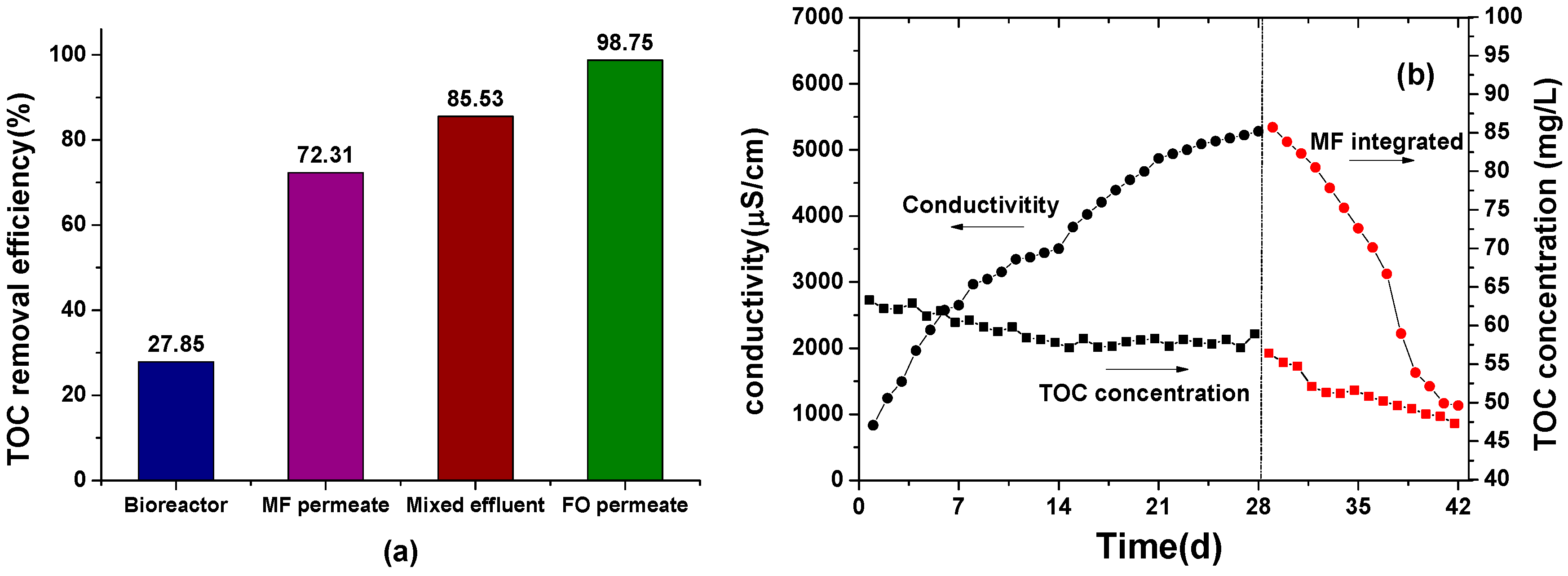
In Figure 8a, the TOC removal efficiency due to the activated sludge (i.e., for the OMBR system only) was only 27.85% for two weeks, while the TOC removal efficiency of the FO membrane was more than 98.75%. Qiu et al. [45] have reported that 98% of TOC removal by OMBR, while, in a recent study by Achilli et al. [8], it was shown that more than 99.8% of TOC was removed with submerged OMBR. This is due to the FO membrane having a high rejection of organic materials which corroborates with previous studies [24,46]. Besides, in a recent review article focusing on the performance of stand-alone FO process, it was demonstrated that TOC rejection by FO membranes was more than 99.9% [47]. Regarding the performance of MF system, the TOC rejection was about 72.31%, which is slightly lower than previous studies (i.e., >80%), but it also depends on the various effects, such as the organic loading rate, the HRT and the SRT [29,48,49]. Finally, considering the total rejection for the hybrid system (i.e., MF effluent and diluted DS), the TOC removal was about 85.53%.
Results in Figure 8b show that the salinity in the bioreactor keeps increasing during the first two weeks when MF was not in operation. Such effect can be readily explained by Equation (9). In fact, the phenomenon of RSF in FO process leads to the transport of solutes from the draw solution to the bioreactor. Thus, the accumulation of feed solutes (Cin), the draw solutes permeating through the FO membrane (Js) and the absence of MF (Jmf) all contributed to the elevated salinity condition in the OMBR. In fact the conductivity increased from 834 to 5400 μS/cm during the first 4 weeks when MF was not operated. Microorganism can be affected by the high salinity environment, i.e., some microorganisms might be inactivated because they are unable to withstand and adapt to high salinity environment, the conductivity higher than 10,000 μS/cm was reported would inhibit the activity of microorganisms [46,50,51]. After integrating MF, the salinity dropped significantly from 5400 to 1100 μS/cm in only two weeks, suggesting that MF is efficient in mitigating the salinity build up inside the reactor. Compared to the FDFO-MBR, TOC concentration in the bioreactor of MF-FDFO-MBR system is lower than FDFO-MBR system which could be attributed to a higher microbial activity in the MF-FDFO-MBR due to its lower salinity based on the result that high salinity could cause the loss of metabolic activity, the release of soluble microbial products and the reduction of the capacity to sustain shock loads [51,52].

4. Conclusions

Three different fertilizers were studied in the novel MF-FDFO-MBR hybrid system and the performance of the process was also studied by investigating different operating parameters: draw solution concentration, FO DS flow rate, and imposed MF flux. Finally, salt accumulation in the MF-FDFOMBR was compared to FDFO-MBR system and TOC removal efficiency was evaluated.
  • This study demonstrated that the integration of the MF membrane could effectively control the salinity and enhance the stable FO flux and metabolic activity in the OMBR.
  • The hydrodynamic conditions were found to have significant effect on the FO water flux and reverse salt flux.
  • The optimum conditions for this hybrid system was found as follow: SOA as fertilizer DS, draw solution concentration of 1 M, FO draw solution flow rate of 200 mL/min and MF imposed flux of 10 LMH.
  • In order to drive OMBR from laboratory research to real practical applications, the water flux of FO membrane must be improved and reverse salt flux must be decreased, which require breakthroughs in the development of FO membranes, draw solutions, operating conditions and other novel strategies.

Supplementary Materials

The supplementary materials are available online at www.mdpi.com/2073-4441/9/1/21/s1.

Acknowledgments

The research reported in this paper was supported by a SEED Fund from King Abdullah University of Science and Technology (KAUST), Saudi Arabia and Doctoral Program of Higher Education of China (20130075110006).

Author Contributions

For this research article Jin Wang and Sherub Phuntsho has conceived and designed the experiments; Jin Wang performed the experiments, Nirenkumar Pathak helped during material procurement and initial instrumental analysis, Laura Chekli helped in data analysis and manuscript correction, Youngjin Kim contributed for mathematical model development, Dengxin Li provided valuable comments for manuscript sumbission and Ho Kyong Shon supervised overall project including collaboration with SEED funding institution KAUST.

Conflicts of Interest

The authors declare no conflict of interest.

References

  1. Trussell, R.R. Potential for Expanding the Nation’s Water Supply through Reuse of Municipal Wastewater; The National Academies Press: Washington, DC, USA, 2012. [Google Scholar]
  2. Clay, J. World Agriculture and the Environment: A Commodity-by-Commodity Guide to Impacts and Practices; Island Press: Washington, DC, USA, 2004; p. 116. [Google Scholar]
  3. Johansson, R.C.; Tsur, Y.; Roe, T.L.; Doukkali, R.; Dinar, A. Pricing irrigation water: A review of theory and practice. Water Policy 2002, 4, 173–199. [Google Scholar] [CrossRef]
  4. Agarwal, A.; Ng, W.J.; Liu, Y. Principle and applications of microbubble and nanobubble technology for water treatment. Chemosphere 2011, 84, 1175–1180. [Google Scholar] [CrossRef] [PubMed]
  5. Judd, S. Mbr Book: Principles and Applications of Membrane Bioreactors for Water and Wastewater Treatment; Butterworth-Heinemann: Oxford, UK, 2010. [Google Scholar]
  6. Lay, W.C.L.; Liu, Y.; Fane, A.G. Impacts of salinity on the performance of high retention membrane bioreactors for water reclamation: A review. Water Res. 2010, 44, 21–40. [Google Scholar] [CrossRef] [PubMed]
  7. Zhao, S.; Zou, L.; Tang, C.Y.; Mulcahy, D. Recent developments in forward osmosis: Opportunities and challenges. J. Membr. Sci. 2012, 396, 1–21. [Google Scholar] [CrossRef]
  8. Achilli, A.; Cath, T.Y.; Marchand, E.A.; Childress, A.E. The forward osmosis membrane bioreactor: A low fouling alternative to MBR processes. Desalination 2009, 239, 10–21. [Google Scholar] [CrossRef]
  9. Cornelissen, E.R.; Harmsen, D.; Korte, K.F.D.; Ruiken, C.J.; Qin, J.J.; Oo, H.; Wessels, L.P. Membrane fouling and process performance of forward osmosis membranes on activated sludge. J. Membr. Sci. 2008, 319, 158–168. [Google Scholar] [CrossRef]
  10. Yap, W.J.; Zhang, J.; Lay, W.C.; Cao, B.; Fane, A.G.; Liu, Y. State of the art of osmotic membrane bioreactors for water reclamation. Bioresour. Technol. 2012, 122, 217–222. [Google Scholar] [CrossRef] [PubMed]
  11. Holloway, R.W.; Regnery, J.; Nghiem, L.D.; Cath, T.Y. Removal of trace organic chemicals and performance of a novel hybrid ultrafiltration-osmotic membrane bioreactor. Environ. Sci. Technol. 2014, 48, 10859–10868. [Google Scholar] [CrossRef] [PubMed]
  12. Schwarzenbach, R.P.; Escher, B.I.; Fenner, K.; Hofstetter, T.B.; Johnson, C.A.; Von, G.U.; Wehrli, B. The challenge of micropollutants in aquatic systems. Science 2006, 313, 1072–1077. [Google Scholar] [CrossRef] [PubMed]
  13. Cath, T.; Childress, A.; Elimelech, M. Forward osmosis: Principles, applications, and recent developments. J. Membr. Sci. 2006, 281, 70–87. [Google Scholar] [CrossRef]
  14. Wang, X.; Chang, V.W.C.; Tang, C.Y. Osmotic membrane bioreactor (OMBR) technology for wastewater treatment and reclamation: Advances, challenges, and prospects for the future. J. Membr. Sci. 2016, 504, 113–132. [Google Scholar] [CrossRef]
  15. Chekli, L.; Phuntsho, S.; Kim, J.E.; Kim, J.; Choi, J.Y.; Choi, J.S.; Kim, S.; Kim, J.H.; Hong, S.; Sohn, J. A comprehensive review of hybrid forward osmosis systems: Performance, applications and future prospects. J. Membr. Sci. 2015, 497, 430–449. [Google Scholar] [CrossRef]
  16. Alturki, A.; McDonald, J.; Khan, S.J.; Hai, F.I.; Price, W.E.; Nghiem, L.D. Performance of a novel osmotic membrane bioreactor (OMBR) system: Flux stability and removal of trace organics. Bioresour. Technol. 2012, 113, 201–206. [Google Scholar] [CrossRef] [PubMed]
  17. Hancock, N.T.; Cath, T.Y. Solute coupled diffusion in osmotically driven membrane processes. Environ. Sci. Technol. 2009, 43, 6769–6775. [Google Scholar] [CrossRef] [PubMed]
  18. Achilli, A.; Cath, T.Y.; Childress, A.E. Selection of inorganic-based draw solutions for forward osmosis applications. J. Membr. Sci. 2010, 364, 233–241. [Google Scholar] [CrossRef]
  19. Phuntsho, S.; Hong, S.; Elimelech, M.; Shon, H.K. Forward osmosis desalination of brackish groundwater: Meeting water quality requirements for fertigation by integrating nanofiltration. J. Membr. Sci. 2013, 436, 1–15. [Google Scholar] [CrossRef]
  20. Phuntsho, S.; Shon, H.K.; Hong, S.; Lee, S.; Vigneswaran, S. A novel low energy fertilizer driven forward osmosis desalination for direct fertigation: Evaluating the performance of fertilizer draw solutions. J. Membr. Sci. 2011, 375, 172–181. [Google Scholar] [CrossRef]
  21. Phuntsho, S.; Shon, H.K.; Majeed, T.; El Saliby, I.; Vigneswaran, S.; Kandasamy, J.; Hong, S.; Lee, S. Blended fertilizers as draw solutions for fertilizer-drawn forward osmosis desalination. Environ. Sci. Technol. 2012, 46, 4567–4575. [Google Scholar] [CrossRef] [PubMed]
  22. Kim, Y.; Chekli, L.; Shim, W.G.; Phuntsho, S.; Li, S.; Ghaffour, N.; Leiknes, T.; Shon, H.K. Selection of suitable fertilizer draw solute for a novel fertilizer-drawn forward osmosis-anaerobic membrane bioreactor hybrid system. Bioresour. Technol. 2016, 210, 26–34. [Google Scholar] [CrossRef] [PubMed]
  23. Tang, C.Y.; She, Q.; Lay, W.C.L.; Wang, R.; Fane, A.G. Coupled effects of internal concentration polarization and fouling on flux behavior of forward osmosis membranes during humic acid filtration. J. Membr. Sci. 2010, 354, 123–133. [Google Scholar] [CrossRef]
  24. Lay, W.C.L.; Zhang, Q.; Zhang, J.; Mcdougald, D.; Tang, C.; Wang, R.; Liu, Y.; Fane, A.G. Study of integration of forward osmosis and biological process: Membrane performance under elevated salt environment. Desalination 2011, 283, 123–130. [Google Scholar] [CrossRef]
  25. Sun, F.Y.; Wang, X.M.; Li, X.Y. Change in the fouling propensity of sludge in membrane bioreactors (MBR) in relation to the accumulation of biopolymer clusters. Bioresour. Technol. 2011, 102, 4718–4725. [Google Scholar] [CrossRef] [PubMed] [Green Version]
  26. Kawasaki, K.; Maruoka, S.; Katagami, R.; Bhatta, C.P.; Omori, D.; Matsuda, A. Effect of initial MLSS on operation of submerged membrane activated sludge process. Desalination 2011, 281, 334–339. [Google Scholar] [CrossRef]
  27. Lay, W.C.L.; Zhang, J.; Tang, C.; Wang, R.; Liu, Y.; Fane, A.G. Factors affecting flux performance of forward osmosis systems. J. Membr. Sci. 2012, 394–395, 151–168. [Google Scholar] [CrossRef]
  28. Janga, N.; Ren, X.; Kim, G.; Ahn, C.; Cho, J.; Kim, I.S. Characteristics of soluble microbial products and extracellular polymeric substances in the membrane bioreactor for water reuse. Desalination 2006, 202, 90–98. [Google Scholar] [CrossRef]
  29. Johir, M.A.; Vigneswaran, S.; Sathasivan, A.; Kandasamy, J.; Chang, C.Y. Effect of organic loading rate on organic matter and foulant characteristics in membrane bio-reactor. Bioresour. Technol. 2012, 113, 154–160. [Google Scholar] [CrossRef] [PubMed]
  30. Chou, S.; Lei, S.; Rong, W.; Tang, C.Y.; Qiu, C.; Fane, A.G. Characteristics and potential applications of a novel forward osmosis hollow fiber membrane. Desalination 2010, 261, 365–372. [Google Scholar] [CrossRef]
  31. Xiao, D.; Tang, C.Y.; Zhang, J.; Lay, W.C.L.; Wang, R.; Fane, A.G. Modeling salt accumulation in osmotic membrane bioreactors: Implications for FO membrane selection and system operation. J. Membr. Sci. 2011, 366, 314–324. [Google Scholar] [CrossRef]
  32. Zhang, J.; Chua, H.C.; Zhou, J.; Fane, A.G. Factors affecting the membrane performance in submerged membrane bioreactors. J. Membr. Sci. 2006, 284, 54–66. [Google Scholar] [CrossRef]
  33. Mccutcheon, J.R.; Elimelech, M. Influence of concentrative and dilutive internal concentration polarization on flux behavior in forward osmosis. J. Membr. Sci. 2006, 284, 237–247. [Google Scholar] [CrossRef]
  34. Kim, Y.; Lee, S.; Shon, H.K.; Hong, S. Organic fouling mechanisms in forward osmosis membrane process under elevated feed and draw solution temperatures. Desalination 2015, 355, 169–177. [Google Scholar] [CrossRef]
  35. Holloway, R.W.; Wait, A.S.; Fernandes da Silva, A.; Herron, J.; Schutter, M.D.; Lampi, K.; Cath, T.Y. Long-term pilot scale investigation of novel hybrid ultrafiltration-osmotic membrane bioreactors. Desalination 2015, 363, 64–74. [Google Scholar] [CrossRef]
  36. Zou, S.; He, Z. Enhancing wastewater reuse by forward osmosis with self-diluted commercial fertilizers as draw solutes. Water Res. 2016, 99, 235–243. [Google Scholar] [CrossRef] [PubMed]
  37. Goosen, M.F.A.; Sablani, S.S.; Al-Hinai, H.; Al-Obeidani, S.; Al-Belushi, R.; Jackson, D. Fouling of reverse osmosis and ultrafiltration membranes: A critical review. Sep. Sci. Technol. 2005, 39, 2261–2297. [Google Scholar] [CrossRef]
  38. Le-Clech, P.; Chen, V.; Fane, T.A.G. Fouling in membrane bioreactors used in wastewater treatment. J. Membr. Sci. 2006, 284, 17–53. [Google Scholar] [CrossRef]
  39. Wang, X.; Yuan, B.; Chen, Y.; Li, X.; Ren, Y. Integration of micro-filtration into osmotic membrane bioreactors to prevent salinity build-up. Bioresour. Technol. 2014, 167, 116–123. [Google Scholar] [CrossRef] [PubMed]
  40. Baker, J.S.; Dudley, L.Y. Biofouling in membrane systems—A review. Desalination 1998, 118, 81–89. [Google Scholar] [CrossRef]
  41. Mohammadi, T.; Moghadam, M.K.; Madaeni, S.S. Hydrodynamic factors affecting flux and fouling during reverse osmosis of seawater. Desalination 2003, 151, 239–245. [Google Scholar] [CrossRef]
  42. Gray, G.T.; Mccutcheon, J.R.; Elimelech, M. Internal concentration polarization in forward osmosis: Role of membrane orientation. Desalination 2006, 197, 1–8. [Google Scholar] [CrossRef]
  43. Babu, B.R.; Rastogi, N.K.; Raghavarao, K.S.M.S. Effect of process parameters on transmembrane flux during direct osmosis. J. Membr. Sci. 2006, 280, 185–194. [Google Scholar] [CrossRef]
  44. Navaratna, D.; Jegatheesan, V. Implications of short and long term critical flux experiments for laboratory-scale MBR operations. Bioresour. Technol. 2011, 102, 5361–5369. [Google Scholar] [CrossRef] [PubMed]
  45. Qiu, G.; Ting, Y.P. Direct phosphorus recovery from municipal wastewater via osmotic membrane bioreactor (OMBR) for wastewater treatment. Bioresour. Technol. 2014, 170, 221–229. [Google Scholar] [CrossRef] [PubMed]
  46. Wang, X.; Yao, C.; Bo, Y.; Li, X.; Ren, Y. Impacts of sludge retention time on sludge characteristics and membrane fouling in a submerged osmotic membrane bioreactor. Bioresour. Technol. 2014, 161, 340–347. [Google Scholar] [CrossRef] [PubMed]
  47. Coday, B.D.; Yaffe, B.G.; Xu, P.; Cath, T.Y. Rejection of trace organic compounds by forward osmosis membranes: A literature review. Environ. Sci. Technol. 2014, 48, 3612–3624. [Google Scholar] [CrossRef] [PubMed]
  48. Lee, Y.; Cho, J.; Seo, Y.; Lee, J.W.; Ahn, K.H. Modeling of submerged membrane bioreactor process for wastewater treatment. Desalination 2002, 146, 451–457. [Google Scholar] [CrossRef]
  49. Kitagawa, S.; Oda, Y.; Sasakawa, M.; Itonaga, T. Membrane bioreactor (MBR) performance for reducing energy demand. Thembrsite Com. 2012. Available online: http://www.thembrsite.com/about/ (accessed on 25 August 2016).
  50. Pophali, G.R.; Kaul, S.N.; Mathur, S. Influence of hydraulic shock loads and TDS on the performance of large-scale CETPs treating textile effluents in India. Water Res. 2003, 37, 353–361. [Google Scholar] [CrossRef]
  51. Yogalakshmi, K.N.; Joseph, K. Effect of transient sodium chloride shock loads on the performance of submerged membrane bioreactor. Bioresour. Technol. 2010, 101, 7054–7061. [Google Scholar] [CrossRef] [PubMed]
  52. Rene, E.R.; Kim, S.J.; Park, H.S. Effect of COD/N ratio and salinity on the performance of sequencing batch reactors. Bioresour. Technol. 2008, 99, 839–846. [Google Scholar] [CrossRef] [PubMed]
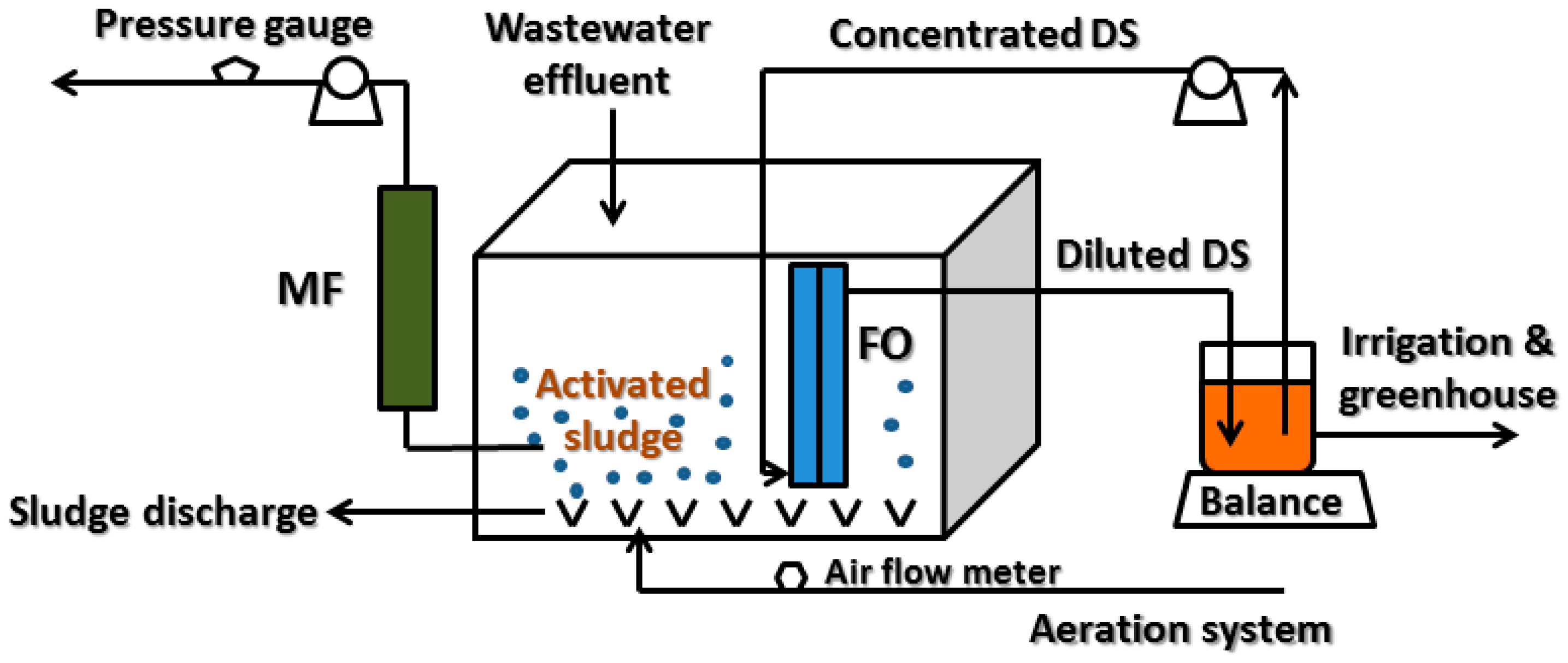
Figure 1. Flow diagram of the MF-FDFO-MBR hybrid system used in this study.
Water 09 00021 g001
Figure 2. Mass balance in the OMBR-MF system.
Water 09 00021 g002
Figure 3. (a) Water flux of different fertilizer draw solutions in the MF-FDFO-MBR hybrid system; and (b) specific reverse salt flux of different fertilizer draw solutions in the MF-FDFO-MBR hybrid system (Feed solution: Synthetic wastewater; DS concentration: 1 M; Flow rate: 200 mL/min, Temperature: 22 ± 0.5 °C).
Water 09 00021 g003
Figure 4. (a) Water flux recovery rates of different fertilizer draw solutions; and (b) fouled membrane surface.
Water 09 00021 g004
Figure 5. (a) Water flux of different DS concentrations in the MF-FDFO-MBR hybrid system; and (b) RSF of different DS concentrations in the MF-FDFO-MBR hybrid system (DS: SOA; Feed solution: Synthetic wastewater; Flow rate: 200 mL/min; Temperature: 22 ± 0.5 °C).
Water 09 00021 g005
Figure 6. (a) Water flux of different DS flow rates in the MF-FDFO-MBR hybrid system; and (b) RSF of different DS flow rates in the MF-FDFO-MBR hybrid system (DS: SOA; Feed solution: Synthetic wastewater; DS concentration: 1 M; Temperature: 22 ± 0.5 °C).
Water 09 00021 g006
Figure 7. (a) Water flux of different MF imposed fluxes in the MF-FDFO-MBR hybrid system; and (b) MF outlet pressure change in the MF-FDFO-MBR hybrid system (DS: SOA; Feed solution: Synthetic wastewater; DS concentration: 1 M; DS flow rate: 200 mL/min, Temperature: 22 ± 0.5 °C).
Water 09 00021 g007
Figure 8. (a) TOC removal efficiency; and (b) variation of conductivity and TOC concentration in the bioreactor of the MF-FDFO-MBR hybrid system.
Water 09 00021 g008
Table 1. Composition of the synthetic municipal wastewater used in this study [29].
ComponentsUnitValues
Glucosemg/L80.50
NH4Clmg/L14.70
KH2PO4mg/L10.50
Starchmg/L85.30
Peptonemg/L18.00
Milk powdermg/L108.40
Yeastmg/L50.00
Total Organic Carbonmg/L92.31
Total Nitrogenmg/L42.32
Total Phosphorusmg/L10.48