Article

Effects of Electrical Stimulation on the Degradation of Azo Dye in Three-Dimensional Biofilm Electrode Reactors

School of Energy and Environment, Southeast University, Nanjing 210096, China
*
Author to whom correspondence should be addressed.
Water 2017, 9(5), 301; https://doi.org/10.3390/w9050301
Submission received: 22 March 2017 / Revised: 17 April 2017 / Accepted: 20 April 2017 / Published: 25 April 2017

Abstract

:
Three-dimensional biofilm electrode reactors (3D-BERs) were constructed to degrade the azo dye Reactive Brilliant Red (RBR) X-3B. The 3D-BERs with different influent concentrations and external voltages were individually studied to investigate their influence on the removal of X-3B. Experimental results showed that 3D-BERs have good X-3B removal efficiency; even when the influent concentration was 800 mg/L, removal efficiency of 73.4% was still achieved. In addition, the X-3B removal efficiency stabilized shortly after the influent concentration increased. In 3D-BERs, the average X-3B removal efficiency increased from 52.8% to 85.4% when the external voltage rose from 0 to 2 V. We further identified the intermediate products via UV-Vis and gas chromatography-mass spectrometry (GC-MS) analyses, and discussed the potential mechanism of degradation. After the conjugate structure of X-3B was destroyed, all of the substances generated mainly consisted of lower-molecular-weight organics.

1. Introduction

Biofilm electrode reactors (BERs) have been studied by various researchers as an effective means of removing pollutants in wastewater treatment processes [1,2,3,4]. In such applications, water electrolysis produces hydrogen gas (H2), which can be utilized by microorganisms on the surface of the cathode as an electron donor [5]. The three-dimensional BER (3D-BER) developed in recent years has a higher treatment efficiency due to a higher surface area-to-volume ratio [6,7]. Many studies on 3D-BERs have been reported. For example, Hao et al. [8] applied a 3D-BER to treat municipal wastewater and observed a maximum nitrate removal of 98.3% at a C/N ratio of 3.0 and a hydraulic retention time (HRT) of 7 h. Nageswara et al. [6] used a 3D-BER to treat landfill leachate and found that about 60–64% of the chemical oxygen demand (COD) was removed within 1 h, which was nearly 5–7 times greater than in the control group. Zhao et al. [9] used activated carbon fiber (ACF)/Fe as the anode and ACF/Ti as the cathode in a 3D-BER to treat Acid Orange 7, with an almost 100% removal efficiency. Zhang et al. [10] applied 3D-BERs to treat sulfamethoxazole (SMX) and tetracycline (TC) and reported significantly reduced antibiotic concentrations, achieving removal rates of 88.9−93.5% and 89.3−95.6% for SMX and TC, respectively.
Azo dyes, which contain one or more –N=N– groups [11], are widely used in the cosmetic, varnish, textile, and paper industries [12]. They are very stable in the environment and difficult to degrade through conventional aerobic treatment processes [13,14]. Traditional physicochemical methods, including adsorption, coagulation/flocculation, chemical precipitation, and even the ion exchange process, can achieve considerable treatment efficiencies; however, they have complex operational requirements and high maintenance costs [15]. Meanwhile, with biological treatment methods, azo dye molecules require anaerobic conditions for degradation into corresponding aromatic amines, and further degradation into simpler compounds under aerobic conditions [16,17]. Moreover, some studies have reported that wastewater containing azo dye can be removed in bioelectrochemical systems under anaerobic conditions. Sreelatha et al. [18] achieved a maximum AMIDO BLACK 10B (C.I. Acid Black 10B) removal of 69.9% with bio-electrochemical treatment. Zhang et al. [19] used a BER to treat Reactive Brilliant Red (RBR) X-3B and achieved a color removal efficiency of 75.8%. Therefore, using BERs to remove azo dyes is a feasible method that deserves further integration.
In our previous study [20], two-dimensional BERs (2D-BERs) with cathodes of different surface areas, a cathode filled with granular activated carbon (GAC) and anodes composed of different materials were used to degrade azo dye X-3B. The average X-3B removal efficiency reached 75.7% in the best condition of 2D-BER. However, when the initial dye concentration was increased from 25 to 200 mg/L, the removal efficiency decreased sharply from 76.2% to 39.3% [21]. It also took a long time for the 2D-BER to reach a stable removal efficiency when the dye concentration changed. In this study, we constructed a novel 3D-BER that introduces activated carbon into a 2D-BER as the third electrode. The average X-3B removal efficiencies were investigated with different initial dye concentrations and applied voltages. Ultraviolet-visible spectroscopy (UV-Vis) and gas chromatography–mass spectrometry (GC–MS) were used to analyze the effluent of the cathode and anode in the 3D-BER to explore possible degradation products and pathways.

2. Materials and Methods

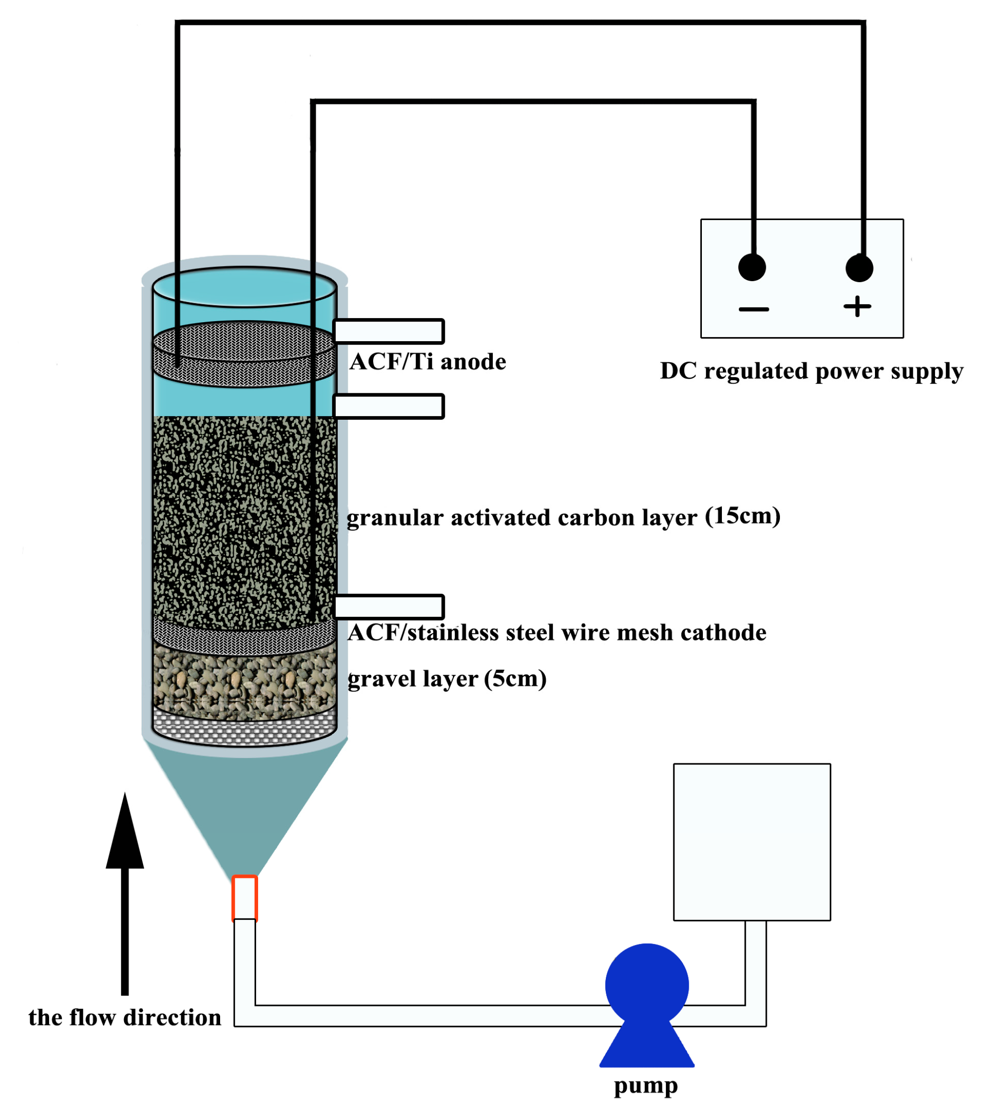
2.1. Reactor Configuration

Figure 1 shows a schematic diagram of the reactor used in this study. The reactor was made of polycarbonate plastic, with dimensions of 30 cm (diameter) × 50 cm (height). The effective working volume of the reactor was 2.5 L. All the reactors were tightly sealed in order to maintain anaerobic conditions. It had a conical water inlet at the bottom (5 cm) and three water outlets at the cathode, anode, and top. From the bottom upward, there were four layers, followed by a 5 cm deep bottom gravel layer (3–6 mm diameter), an ACF/stainless steel wire mesh cathode, a 15 cm deep layer of granular activated carbon (GAC) (3–5 mm diameter, specific area 500–900 m2/g), and an ACF/Ti anode. There were 5 cm between the anode and the GAC layer. A single cathode and anode were connected by titanium wire (1 mm in diameter) to a DC power supply (1 V DC) to create a loop circuit, and epoxy was used to prevent the Ti wire from making direct electrical contact with the cathode [21]. The X-3B artificial wastewater was continuously pumped into the reactor from the water intake at the bottom of the reactor by a peristaltic pump (BT-100; Baoding Longer Precision Pump Co., Ltd., Baoding, China). The HRT was 2.5 days. A DC power supply (IT6322; ITECH Electronic Co., Ltd., Nanjing, China) provided the current for each reactor [21].

2.2. System Operation

The chemical composition of 1 L nutrient solution was 400 mg glucose, 330 mg NaCl, 134 mg NH4Cl, 33 mg NaH2PO4, 18 mg Na2HPO4, 340 mg NaHCO3, 15 mg MgSO4·7H2O, 2 mg ZnSO4·7H2O, 2.2 mg MnSO4·H2O, 1 mg FeSO4, 0.24 mg CoCl2·6H2O, 15 mg CaCl2, and 1.17 mg (NH4)6Mo7O24·4H2O. One liter anaerobic sludge (mixed liquor suspended solids: 50 g/L, COD: 5−10 g/L, total carbohydrate: 0.3–2 g/L) sampled from the East City Municipal Wastewater Treatment Plant of Nanjing, China, was introduced into the reactors for microbial inoculation. Analytical grade RBR X-3B dye was used without further purification. For the entire experiment, the influent pH values were approximately 7.6 to stabilize the reaction process. All experiments were conducted at 25 ± 1°C in a controlled climate room. There were three parallel groups in each experiment group and all of the data shown in this study were averaged over three measurements to ensure the repeatability of the experiments.
The experiment consisted of two stages. In the first stage, to investigate the impact of different influent concentrations on X-3B removal efficiency, two groups of 3D-BERs, an experimental group and a control group, were constructed. The structures of the two groups were the same except that the anode and cathode of the control group were not connected to a DC power supply. The external voltage on the experimental group was 1.0 V. The concentration of X-3B was 200 mg/L at the beginning of the experiment, and reached 400, 600, and 800 mg/L on days 18, 36, and 54, respectively.
In the second stage, to investigate the impact of different external voltages on X-3B removal efficiency, six groups of 3D-BERs connected to 0, 0.5, 0.8, 1.0, 1.5, and 2.0 V DC power supplies were constructed. The influent concentration of X-3B was 800 mg/L in all six groups.

2.3. Analytics and Calculations

A UV-Vis spectrophotometer (UV9100, Lab Tech Ltd, Beijing, China) was used to investigate the influent of the BERs over a range of 190−600 nm. To determine the X-3B removal efficiency, influent absorbance values (A1) and effluent absorbance values (A2) were measured, and the X-3B removal efficiency (E) was calculated by the equation:
E = (A1 − A2)/A1 × 100%
All samples were filtered through a 0.45 μm syringe filter to remove suspended solids from the liquid media prior to measurement [11].
The X-3B degradation products were detected using a Gas Chromatograph–Mass Spectrometer (GC–MS, Thermo Fisher Scientific, Waltham, MA, USA) with a DB-5ms capillary column (inner diameter 0.25 mm, length 30 m). High-purity helium was employed as the carrier gas at a flow rate of 1 mL/min. The gasification compartment temperature was first set to 60 °C for 0.5 min, and then was linearly increased to 235 °C at a rate of 25 °C/min. After maintaining at 235 °C for 2 min, it was further linearly increased to 250 °C at a rate of 2 °C/min and then maintained at 250 °C for 5 min. Finally, the temperature of the gasification component was linearly increased to 280 °C at a rate of 15 °C/min and then maintained for 5 min. Molecular weights were scanned in the range of 45−600 m/z. The retention time and sampling volume were 4 min and 1 μL, respectively. Samples were not injected with diversion. The ionization method of mass spectroscopy was electron impact (EI) with the voltage of the electron multiplier at 1605 V. The temperatures of the ion source and the interface were 230 and 280 °C, respectively. Separated components were analyzed by referencing the NIST MS Search 2.0 mass spectral library database. The analysis of X-3Bused the GC-MS choice ion pattern (SIM). The temperature program was as described above. The peak areas of 93, 121, and 136 m/z were used to generate a standard curve [22].

3. Results and Discussion

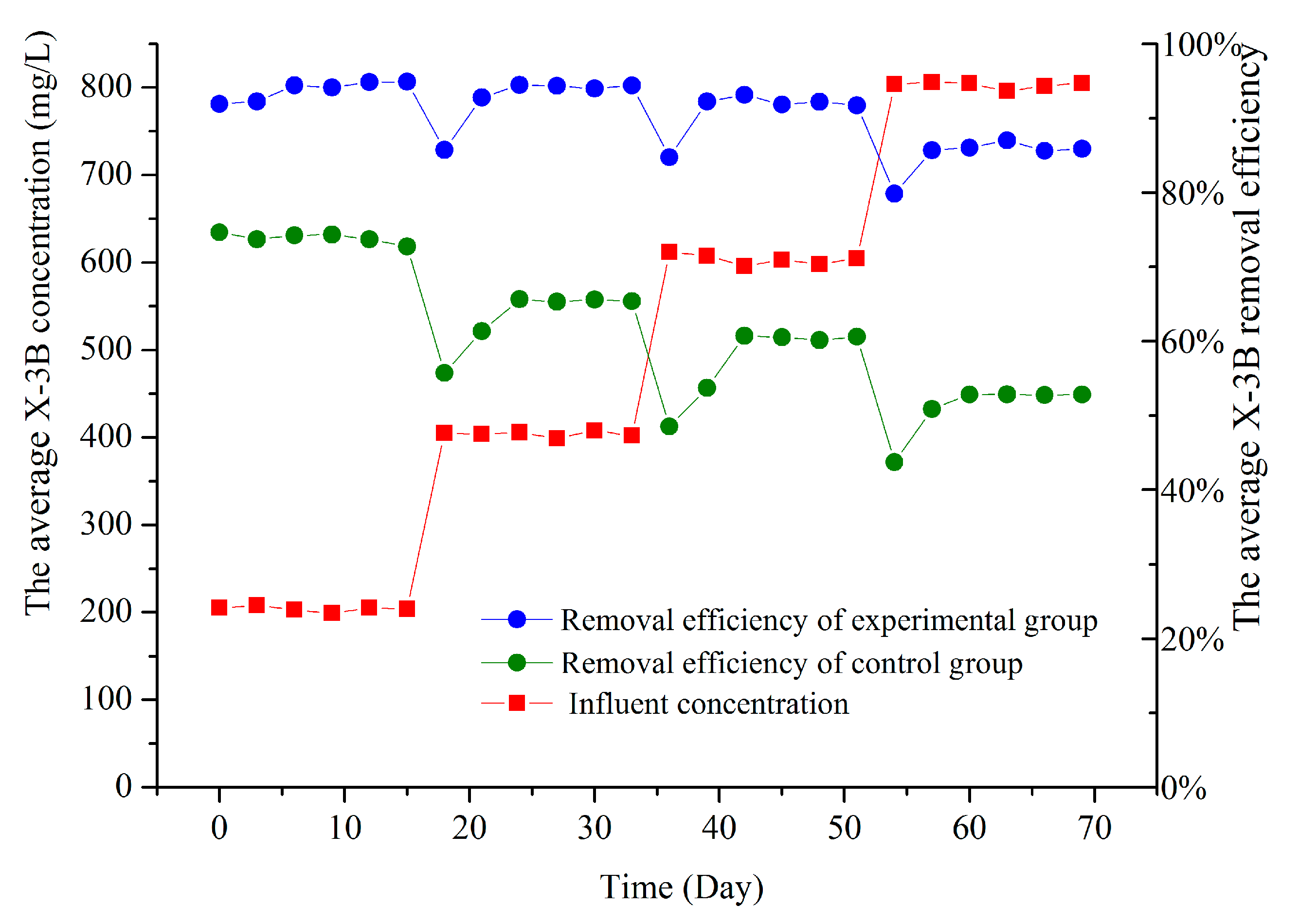
3.1. X-3B Removal Efficiencies at Different Influent Concentrations

First, we investigated the influence of different influent concentrations on 3D-BER X-3B removal efficiency. The average X-3B removal efficiencies with different influent concentrations from days 1 to 70 are shown in Figure 2. When the influent concentrations were 200, 400, 600 and 800 mg/L, the average X-3B removal efficiencies were 93.8%, 85.7%, 80.8% and 73.5%, respectively, in the experimental group and 74.0%, 63.1%, 57.4% and 51.0%, respectively, in the control group. Although the average X-3B removal efficiencies decreased with increasing influent concentration in both the experimental and control groups, the experimental group maintained a good removal efficiency even when the influent concentration was 800 mg/L. Compared with Zhang et al. [19] and Sreelatha et al. [18], the azo dye removal efficiency increased about 20%. Meanwhile, it still had a good removal rate (73.5%) at a high azo dye concentration. The existence of the GAC in the 3D-BERs provided a greater area to which microorganisms could adhere, increasing the total number of microorganisms. Electric current stimulation improved microbial metabolism and azo reductase activity. Concurrently, the surface of the GAC layer was charged by the current to become new GAC electrodes, which can produce anode reactions on the surface [23]. This greatly increased the specific area of the electrodes [24] so that the 3D-BERs still had good removal efficiencies at high X-3B influent concentrations.
In our previous studies, the electrodes of the 2D-BER were fixed in the reactor. The efficiency of organic pollutant contact with the electrodes was low because the inflow containing organic pollutants first mixed with the original water when flowing into the reactor. However, the structure of the GAC layer provided stability in the 3D-BER, as the inflow flowed upstream between gaps in the activated carbon. The organic pollutants in the wastewater could come into direct contact with biofilms in the GAC layer. Compared with traditional 2D-BER, the GAC served as the third electrode, and the reductive reactions occurred on its surface. This structure in the 3D-BER stabilized the X-3B removal efficiency shortly after the influent concentration increased, and concurrently improved the X-3B removal efficiency.

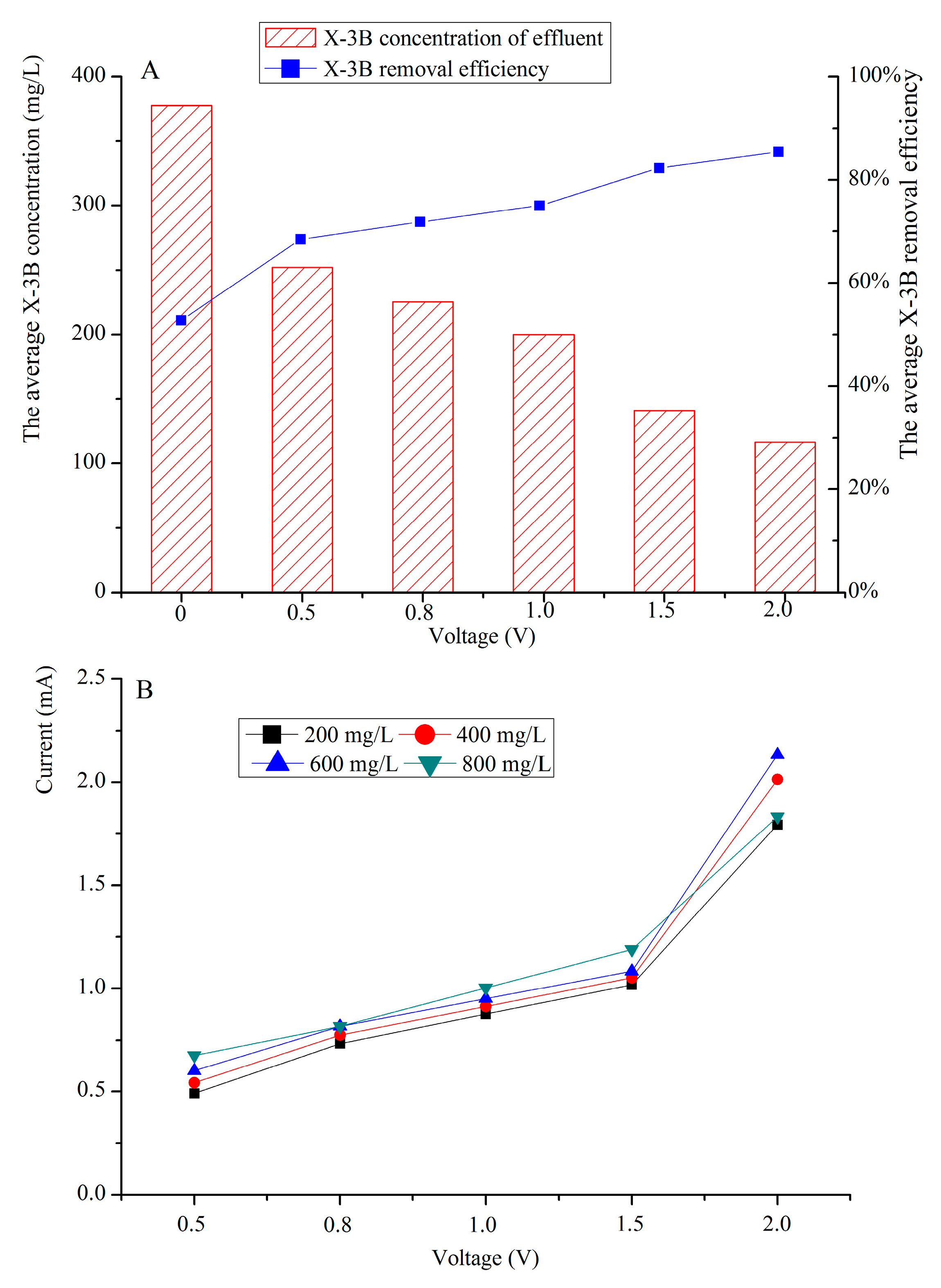
3.2. X-3B Removal Efficiencies under Different External Voltages

Next, we investigated the influence of different external voltages on 3D-BER X-3B removal efficiency. As shown in Figure 3A, when the external voltages were 0, 0.5, 0.8, 1.0, 1.5 and 2.0 V, the average X-3B concentrations in the effluent were 377.70, 252.10, 225.15, 199.92, 141.16 and 116.70 mg/L, respectively, and the average X-3B removal efficiencies were 52.8%, 68.5%, 71.9%, 75.01%, 82.4% and 85.4%, respectively. As shown in Figure 3B, the average currents in the 3D-BERs with different X-3B concentrations were 0.58, 0.79, 0.94, 1.09 and 1.94 mA when the external voltages were 0.5, 0.8, 1.0, 1.5 and 2.0 V, respectively. Compared to the control group without external voltage, the average X-3B removal efficiency with external voltage increased in 3D-BERs. The current in 3D-BERs increased as the external voltage increased.
In our study, the removal of X-3B required electrons gain to reduce the actions of microorganisms under anaerobic conditions. Without the electron from the DC (the control group), only a few microorganisms could degrade the co-substrate to generate electrons, so the X-3B removal efficiency was low in the control group. In the experimental group, with the external voltage forming current in a 3D-BER, more electrons were available for removing X-3B in reduction reactions, and the X-3B removal efficiency increased. The larger the current in a 3D-BER, the more electrons available, and the better the removal efficiency. Electric current stimulation also improved microbial biomass and enzyme activity [10]. At the same time, the surface of the GAC was rich in microorganisms and the formation of this biological cathode greatly reduced mass transfer resistance, facilitating electron transfer from the solution to the electrode [25], so that electrons could move with high efficiency, and the removal efficiency increased. However, high current (more than 20 mA) may inactivate the microorganisms [26] and cause them to fall off [27]. In our experiment, the removal efficiency increased when the external voltage rose from 0.5 to 2 V; the current rose from 0.68 to 1.83 mA; and we did not find microbial inactivation or fall-off. Park et al. [28] found that the maximum nitrate reduction rate was 98% at an applied current of 200 mA. Wang et al. [29] found that even under the operation conditions of 0.36 A, 70% TOC was removed and complete decolorization occurred. Thus, we determined that this voltage range was beneficial for microorganisms.

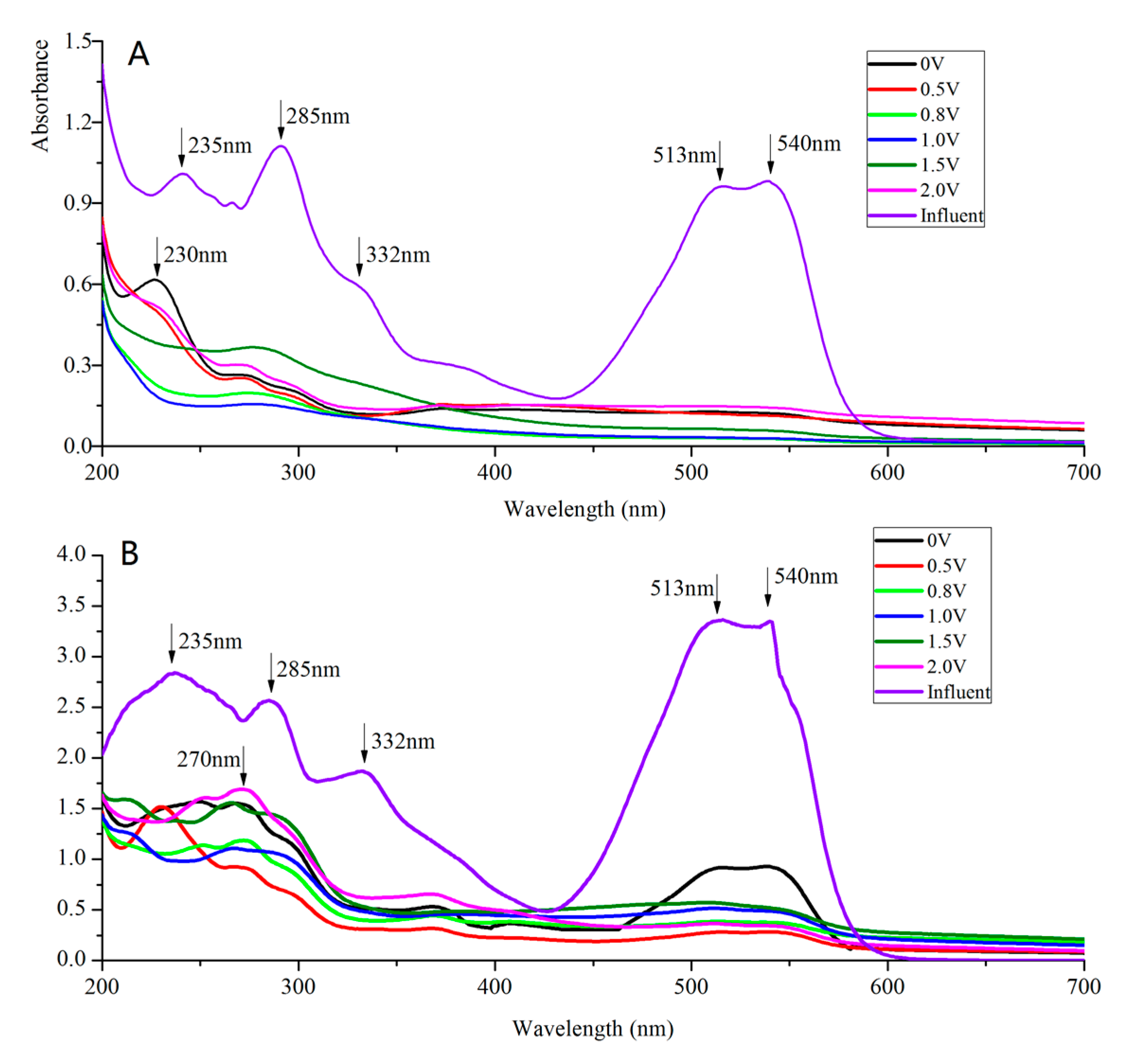
3.3. UV-Vis Spectral Analysis

UV-Vis spectroscopy was conducted to investigate the removal of X-3B. The UV-Vis spectra of the influent and effluent with different external voltages when influent concentrations were 200 and 800 mg/L are shown in Figure 4A,B. This analysis revealed that the absorbance features at 235, 285, 332, 513, and 540 nm declined to different degrees, and the absorbance feature at 513−540 nm in particular declined most obviously. The wide absorbance feature that appeared at 513–540 nm was caused by the conjugated structure n-π, which is responsible for the unique red color of X-3B. The absorbance feature at 513−540 nm declined, demonstrating that the conjugated structure in X-3B was destroyed, causing X-3B discoloration in the solution. The damage to the conjugated structure was due to the strong activity of the –N=N– double bond, at which electron transition easily occurs to generate excited-state electrons and activate structural molecules, destabilizing the carbon atoms attached to azo groups. With the action of hydroxyl radicals, N–C single bonds cracked first, then the destruction of the conjugated structures of X-3B ruptured the azo bond [19,30].
The absorbance features at 235, 285, and 332 nm represented benzene rings, triazine rings, and naphthalene rings, respectively [31,32,33]. Obvious declines of the three absorbance features shown in Figure 4A were observed in effluent with different external voltages when influent concentrations were 200 mg/L. This indicates that the substances generated after the conjugated structure is damaged, such as benzene rings, triazine rings, and naphthalene rings, continue to degrade. A similar phenomenon also occurred when influent concentrations were 800 mg/L, as shown in Figure 4B. In addition, two new peaks, at 230 and 270 nm, may have been the fine multi-peaks of benzene and naphthalene rings (Figure 4A,B). The reduction reaction presumably destroyed the conjugated structure of X-3B and then formed the fine multi-peaks of the aromatic rings [28]. Therefore, the final products in effluent with different external voltages and influent concentrations were small organic molecules that were easily degraded.

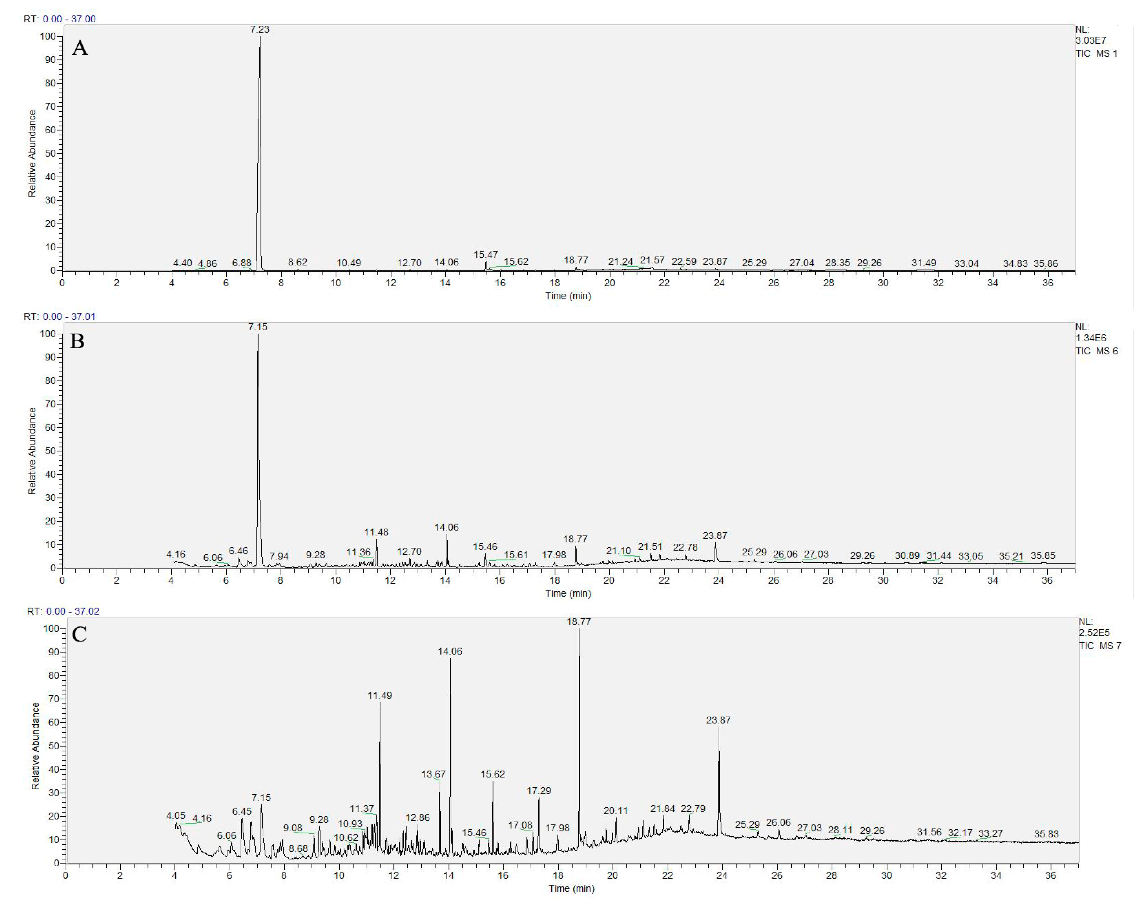
3.4. Identification of Degradation Products

The results of GC-MS chromatographic analysis of the effluent from the cathode, the top of the GAC layer, and the anode are shown in Figure 5, and the chemical formulas of the metabolites are given in Table 1. In the effluent from the cathode, the main product was aniline, and it was at much higher amounts than the other products, which included phenols (C15H24O), esters (C17H24O4), and its derivatives (C7H7NCl2O). Compared to other products, the amount of aniline in the effluent from the GAC layer was still high, and hydrocarbons (C13H24) and esters (C14H26O4) appeared at the same time. Our previous study showed that these kinds of long-chain hydrocarbons are the products of further degradation of naphthalene ring compounds, and the activated carbon layer has the ability to further degrade naphthalene ring compounds [20]. The aniline content in the effluent from the anode significantly decreased, while the content of other products such as C15H24O, C17H24O4, and C14H26O4 greatly increased, indicating that aniline and aromatic amines were further degraded at the anode. Using the microorganisms at the anode surface as electron donors, aniline and aromatic amines were degraded to benzene compounds and naphthalene rings, and some of the intermediates were also degraded to hydrocarbons, phenols, and ester compounds.
Combined with the UV-Vis analysis, we speculated on the degradation pathway of X-3B in 3D-BER. The conjugated structure of X-3B was destroyed first and ruptured the azo bond, then generated the aniline, benzene rings, triazine rings, and naphthalene rings. Naphthalene rings and triazine rings were further degraded to hydrocarbons, aldehydes, and esters, while aniline was concurrently degraded to phenol. The substances generated were mainly lower-molecular-weight organic compounds.

4. Conclusions

We obtained a set of conditions for constructing a 3D-BER for X-3B degradation. The average X-3B removal efficiency reached 73.5% when the influent concentration of X-3B was 800 mg/L. The X-3B removal efficiency stabilized shortly after the influent concentration increased. The average efficiency increased from 72.8% to 95.4% with an influent concentration of 800 mg/L when the external voltage rose from 0 to 2 V. In addition, the intermediate products were identified via UV-Vis and GC-MS analysis, and the potential mechanism was discussed. We determined that after the conjugated structure of X-3B was destroyed, all of the substances generated were composed mainly of lower-molecular-weight organics. Further optimization of the operating conditions (e.g., ionic strength, cathode structure, and temperature) are needed to increase the removal efficiency of azo dye by 3D-BERs.

Acknowledgments

This work was supported by Major Science and Technology Project of Water Pollution Control and Management in China (2012ZX07101005), the Fundamental Research Funds for the Central Universities (2242016K41042), National Natural Science Foundation of China (21277024) and Scientific Research Foundation of Graduate School of Southeast University.

Author Contributions

The manuscript was written by Xian Cao but all the authors contributed to its preparation and review. Experiments were performed by Xiaoqi Li. Data analyses were carried out by Xian Cao, Hui Wang and Zhou Fang in discussion with Jingran Zhang.

Conflicts of Interest

The authors declare no conflict of interest.

References

  1. He, Y.; Wang, Y.H.; Song, X.S. High-effective denitrification of low C/N wastewater by combined constructed wetland and biofilm-electrode reactor (CW-BER). Bioresour. Technol. 2016, 203, 245–251. [Google Scholar] [CrossRef] [PubMed]
  2. Zhong, Y.; Li, X.; Yang, Q.; Wang, D.B.; Yao, F.B.; Li, X.M.; Zhao, J.M.; Xu, Q.X.; Zhang, C.; Zeng, G.M. Complete bromate and nitrate reduction using hydrogen as the sole electron donor in a rotating biofilm-electrode reactor. J. Hazard. Mater. 2016, 307, 82–90. [Google Scholar] [CrossRef] [PubMed]
  3. Zhou, M.; Fu, W.J.; Gu, H.Y.; Lei, L.C. Nitrate removal from groundwater by a novel three-dimensional electrode biofilm reactor. Electrochim. Acta 2007, 52, 6052–6059. [Google Scholar] [CrossRef]
  4. Zhang, S.; Song, H.L.; Yang, X.L.; Long, X.Z.; Liu, X.; Chen, T.Q. Behavior of tetracycline and sulfamethoxazole and their corresponding resistance genes in three-dimensional biofilm-electrode reactors with low current. J. Environ. Sci. Health Part A Tox. Hazard. Subst. Environ. Eng. 2017, 52, 333–340. [Google Scholar] [CrossRef] [PubMed]
  5. Zhao, Y.X.; Zhang, B.G.; Feng, C.P.; Huang, F.Y.; Zhang, P.; Zhang, Z.Y.; Yang, Y.N.; Sugiura, N. Behavior of autotrophic denitrification and heterotrophic denitrification in an intensified biofilm-electrode reactor for nitrate-contaminated drinking water treatment. Bioresour. Technol. 2012, 107, 159–165. [Google Scholar] [CrossRef] [PubMed]
  6. Nageswara, R.N.; Rohit, M.; Nitin, G.; Parameswaran, P.N.; Astik, J.K. Kinetics of electrooxidation of landfill leachate in a three-dimensional carbon bed electrochemical reactor. Chemosphere 2009, 76, 1206–1212. [Google Scholar] [CrossRef] [PubMed]
  7. Hao, R.X.; Meng, C.C.; Li, J.B. An integrated process of three-dimensional biofilm-electrode with sulfur autotrophic denitrification (3DBER-SAD) for wastewater reclamation. Appl. Microbiol. Biotechnol. 2016, 100, 7339–7348. [Google Scholar] [CrossRef] [PubMed]
  8. Hao, R.X.; Li, S.M.; Li, J.B.; Meng, C.C. Denitrification of simulated municipal wastewater treatment plant effluent using a three-dimensional biofilm-electrode reactor: Operating performance and bacterial community. Bioresour. Technol. 2013, 143, 178–186. [Google Scholar] [CrossRef] [PubMed]
  9. Zhao, H.Z.; Yan, S.; Xu, L.N.; Ni, J.R. Removal of Acid Orange 7 in simulated wastewater using a three-dimensional electrode reactor: Removal mechanisms and dye degradation pathway. Chemosphere 2010, 78, 46–51. [Google Scholar] [CrossRef] [PubMed]
  10. Zhang, S.; Song, H.L.; Yang, X.L.; Yang, Y.L.; Yang, K.Y.; Wang, X.Y. Fate of tetracycline and sulfamethoxazole and their corresponding resistance genes in microbial fuel cell coupled constructed wetlands. RSC Adv. 2016, 6, 95999–96005. [Google Scholar] [CrossRef]
  11. Fang, Z.; Song, H.L.; Ning, C.; Li, X.N. Performance of microbial fuel cell coupled constructed wetland system for decolorization of azo dye and bioelectricity generation. Bioresour. Technol. 2013, 144, 165–171. [Google Scholar] [CrossRef] [PubMed]
  12. Rahmani, A.R.; Godini, K.; Nematollahi, D.; Azarian, G.; Maleki, S. Degradation of azo dye C.I. Acid Red 18 using an eco-friendly and continuous electrochemical process. Korean J. Chem. Eng. 2016, 33, 532–538. [Google Scholar] [CrossRef]
  13. Nigam, P.; Banat, I.M.; Singh, D.; Marchant, R. Microbial process for the decolorization of textile effluent containing azo, diazo and reactive dyes. Process Biochem. 1996, 31, 435–442. [Google Scholar] [CrossRef]
  14. Kumar, A.N.; Reddy, C.N.; Mohan, S.V. Biomineralization of azo dye bearing wastewater in periodic discontinuous batch reactor: Effect of microaerophilic conditions on treatment efficiency. Bioresour. Technol. 2015, 188, 56–64. [Google Scholar] [CrossRef] [PubMed]
  15. Cui, D.; Guo, Y.Q.; Lee, H.S.; Cheng, H.Y.; Liang, B.; Kong, F.Y.; Wang, Y.Z.; Huang, L.P.; Xu, M.Y.; Wang, A.J. Efficient azo dye removal in bioelectrochemical system and post-aerobic bioreactor: Optimization and characterization. Chem. Eng. J. 2014, 243, 355–363. [Google Scholar] [CrossRef]
  16. Reddy, C.N.; Kumar, A.N.; Modestra, J.A.; Mohan, S.V. Induction of anoxic microenvironment in multi-phase metabolic shift strategy during periodic discontinuous batch mode operation enhances treatment of azo dye wastewater. Bioresour. Technol. 2014, 165, 241–249. [Google Scholar] [CrossRef] [PubMed]
  17. Mohan, S.V.; Rao, N.C.; Sarma, P.N. Simulated acid azo dye (Acid black 210) wastewater treatment by periodic discontinuous batch mode operation under anoxic–aerobic–anoxic microenvironment conditions. Ecol. Eng. 2007, 31, 242–250. [Google Scholar] [CrossRef]
  18. Sreelatha, S.; Velvizhi, G.; Reddy, C.N.; Modestra, J.A.; Mohan, S.V. Solid electron acceptor effect on biocatalyst activity in treating azo dye based wastewater. RSC Adv. 2015, 5, 95926–95938. [Google Scholar] [CrossRef]
  19. Zhang, Y.; Dou, X.M.; Liu, J.; Yang, M.; Zhang, L.P.; Kamagata, Y. Decolorization of reactive brilliant red X-3B by heterogeneous photo-Fenton reaction using an Fe-Ce bimetal catalyst. Catal. Today 2007, 126, 387–393. [Google Scholar] [CrossRef]
  20. Cao, X.; Gu, F.; Wang, H.; Fang, Z.; Li, X.N. The degradation of azo dye with different cathode and anode structures in biofilm electrode reactors. RSC Adv. 2017, 7, 16854–16860. [Google Scholar] [CrossRef]
  21. Liu, S.T.; Song, H.L.; Wei, S.Z.; Liu, Q.J.; Li, X.N.; Qian, X.W. Effect of direct electrical stimulation on decolorization and degradation of azo dye reactive brilliant red X-3B in biofilm-electrode reactors. Biochem. Eng. J. 2015, 93, 294–302. [Google Scholar] [CrossRef]
  22. Cao, X.; Wang, H.; Li, X.Q.; Fang, Z.; Li, X.N. Enhanced degradation of azo dye by a stacked microbial fuel cell-biofilm electrode reactor coupled system. Bioresour. Technol. 2017, 227, 273–278. [Google Scholar] [CrossRef] [PubMed]
  23. Zhang, X.N.; Huang, W.M.; Wang, X.; Li, H.T.; Lu, H.Y.; Lin, H.B. Biofilm-electrode process with high efficiency for degradation of 2,4-dichlorophenol. Environ. Chem. Lett. 2011, 9, 383–388. [Google Scholar] [CrossRef]
  24. Huang, L.P.; Regan, J.M.; Xie, Q. Electron transfer mechanisms, new applications, and performance of biocathode microbial fuel cells. Bioresour. Technol. 2011, 102, 316–323. [Google Scholar] [CrossRef] [PubMed]
  25. Ter Heijne, A.; Schaetzle, O.; Gimenez, S.; Fabregat-Santiago, F.; Bisquert, J.; Strik, D.P.B.T.B.; Barriere, F.; Buisman, C.J.N.; Hamelers, H.V.M. Identifying charge and mass transfer resistances of an oxygen reducing biocathode. Energ. Environ. Sci. 2011, 4, 5035–5043. [Google Scholar] [CrossRef]
  26. Rau, J.; Knackmuss, H.J.; Stolz, A. Effects of different quinoid redox mediators on the anaerobic reduction of azo dyes by bacteria. Environ. Sci. Technol. 2002, 36, 1497–1504. [Google Scholar] [CrossRef] [PubMed]
  27. Luo, Q.S.; Wang, H.; Zhang, X.H.; Qian, Y. Effect of direct electric current on the cell surface properties of phenol-degrading bacteria. Appl. Environ. Microbiol. 2005, 71, 423–427. [Google Scholar] [CrossRef] [PubMed]
  28. Park, H.I.; Dong, K.K.; Choi, Y.J.; Pak, D. Nitrate reduction using an electrode as direct electron donor in a biofilm-electrode reactor. Process Biochem. 2005, 40, 3383–3388. [Google Scholar] [CrossRef]
  29. Wang, A.; Qu, J.; Liu, H.; Ru, J. Mineralization of an azo dye Acid Red 14 by photoelectro-Fenton process using an activated carbon fiber cathode. Appl. Catal. B Environ. 2008, 84, 393–399. [Google Scholar] [CrossRef]
  30. Li, Z.; Zhang, X.; Lin, J.; Han, S.; Lei, L. Azo dye treatment with simultaneous electricity production in an anaerobic-aerobic sequential reactor and microbial fuel cell coupled system. Bioresour. Technol. 2010, 101, 4440. [Google Scholar] [CrossRef] [PubMed]
  31. Zhang, X.; Li, G.; Wang, Y. Microwave assisted photocatalytic degradation of high concentration azo dye Reactive Brilliant Red X-3B with microwave electrodeless lamp as light source. Dyes Pigment. 2007, 74, 536–544. [Google Scholar] [CrossRef]
  32. Feng, W.; Deng, N.; Hua, H. Degradation mechanism of azo dye C. I. reactive red 2 by iron powder reduction and photooxidation in aqueous solutions. Chemosphere 2000, 41, 1233–1238. [Google Scholar] [CrossRef]
  33. Gao, X.; Zhang, L.; Sun, M.; Xiao, Y.; Su, J. Fast zero-order hydro-cracking reaction of X-3B over crystal Al-Fe alloys: Effect of electrochemical corrosion behaviors. Mater. Des. 2016, 109, 570–579. [Google Scholar] [CrossRef]
Figure 1. Schematic diagram of the reactor.
Water 09 00301 g001
Figure 2. The average X-3B concentration and removal efficiency at different influent concentrations.
Water 09 00301 g002
Figure 3. (A) The average X-3B concentration of effluent and removal efficiency under different external voltages; (B) the relationship between external voltages and the average current.
Water 09 00301 g003
Figure 4. The UV-vis spectrum of the influent and the effluent under different external voltages (A) the influent X-3B = 200 mg/L and (B) the influent X-3B = 800 mg/L.
Water 09 00301 g004
Figure 5. The chromatogram of the effluent (A) the cathode area; (B) the top of the granular activated carbon (GAC) layer and (C) the anode area.
Water 09 00301 g005
Table 1. Gas chromatography-mass spectrometry (GC-MS) analysis results of the effluent from the cathode area, the top of the activated carbon layer and the anode area.
EffluentRetention Time (min)Molecular FormulaChemical ConstructionChemical Name
The cathode area7.23C6H7N Water 09 00301 i001Aniline
14.06C15H24O Water 09 00301 i0022,4-bis(1,1-dimethylethyl)-5-methyl-Phenol
15.47C7H7NCl2O Water 09 00301 i0033,5-dichloropyridin-4-ol
18.77C17H24O4 Water 09 00301 i004Isobutyl pentan-2-yl phthalate
The top of the activated carbon layer6.46C13H24 Water 09 00301 i0055-Undecene,7-ethenyl-
7.15C6H7N Water 09 00301 i006Aniline
14.06C15H24O Water 09 00301 i0072,4-bis(1,1-dimethylethyl)-5-methyl-Phenol
15.47C7H7NCl2O Water 09 00301 i0083,5-dichloropyridin-4-ol
18.77C17H24O4 Water 09 00301 i009Isobutyl pentan-2-yl phthalate
23.87C14H26O4 Water 09 00301 i010Hexanedioic acid, mono(2-rthylhexyl)ester
The anode area6.46C13H24 Water 09 00301 i0115-Undecene,7-ethenyl-
7.15C6H7N Water 09 00301 i012Aniline
14.06C15H24O Water 09 00301 i0132,4-bis(1,1-dimethylethyl)-5-methyl-Phenol
15.47C7H7NCl2O Water 09 00301 i0143,5-dichloropyridin-4-ol
18.77C17H24O4 Water 09 00301 i015Isobutyl pentan-2-yl phthalate
23.87C14H26O4 Water 09 00301 i016Hexanedioic acid, mono(2-rthylhexyl)ester

