
Evaluation of Counter-Rotating Dual-Rotor Permanent-Magnet Flux-Switching Machine with Series and Parallel Stator Teeth
 ,
,  ,
,
Abstract
:1. Introduction
- With a complex magnetic topology due to the two rotors, the interactions between the flux sources and circulating fluxes are also complicated and not yet explored.
- The magnetic coupling between the stator and two rotors, as well as between the series and parallel teeth, could have significant impacts on torque production, cogging torque, torque ripple, losses, etc.
- The counter-rotating (CR) topology brings additional challenges and degrees of freedom that require dedicated analysis.
- With a better understanding, CR-DRPMFSMs can be designed to maximize power density, efficiency, and reliability.
- The knowledge gained would be applicable to other complex multi-rotor and flux-modulation machine topologies.
- There are practical economic and technological benefits for the proposed direct-drive wind power generation systems which utilize high-torque-density machines.
2. Characteristics of Wind Power Generation
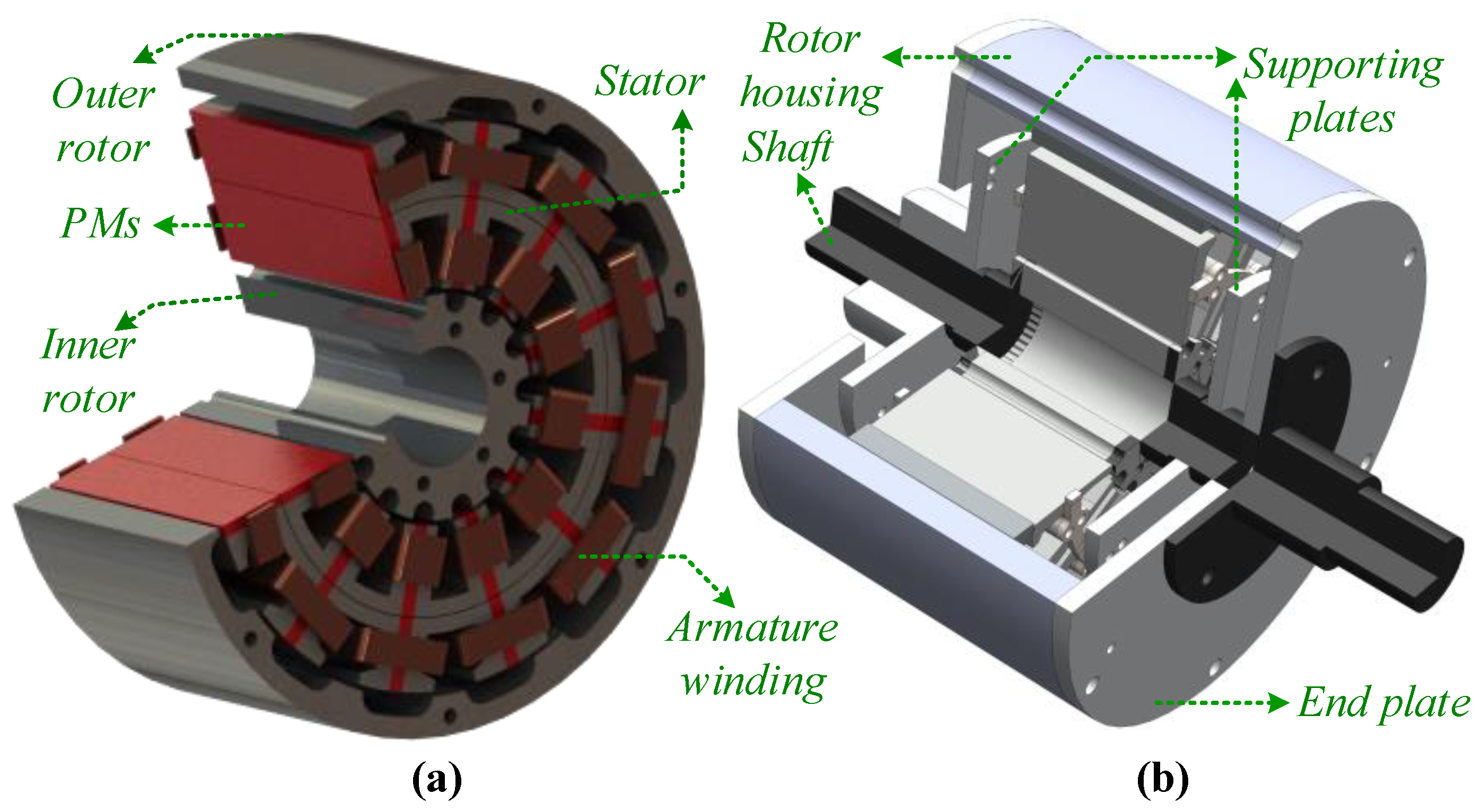
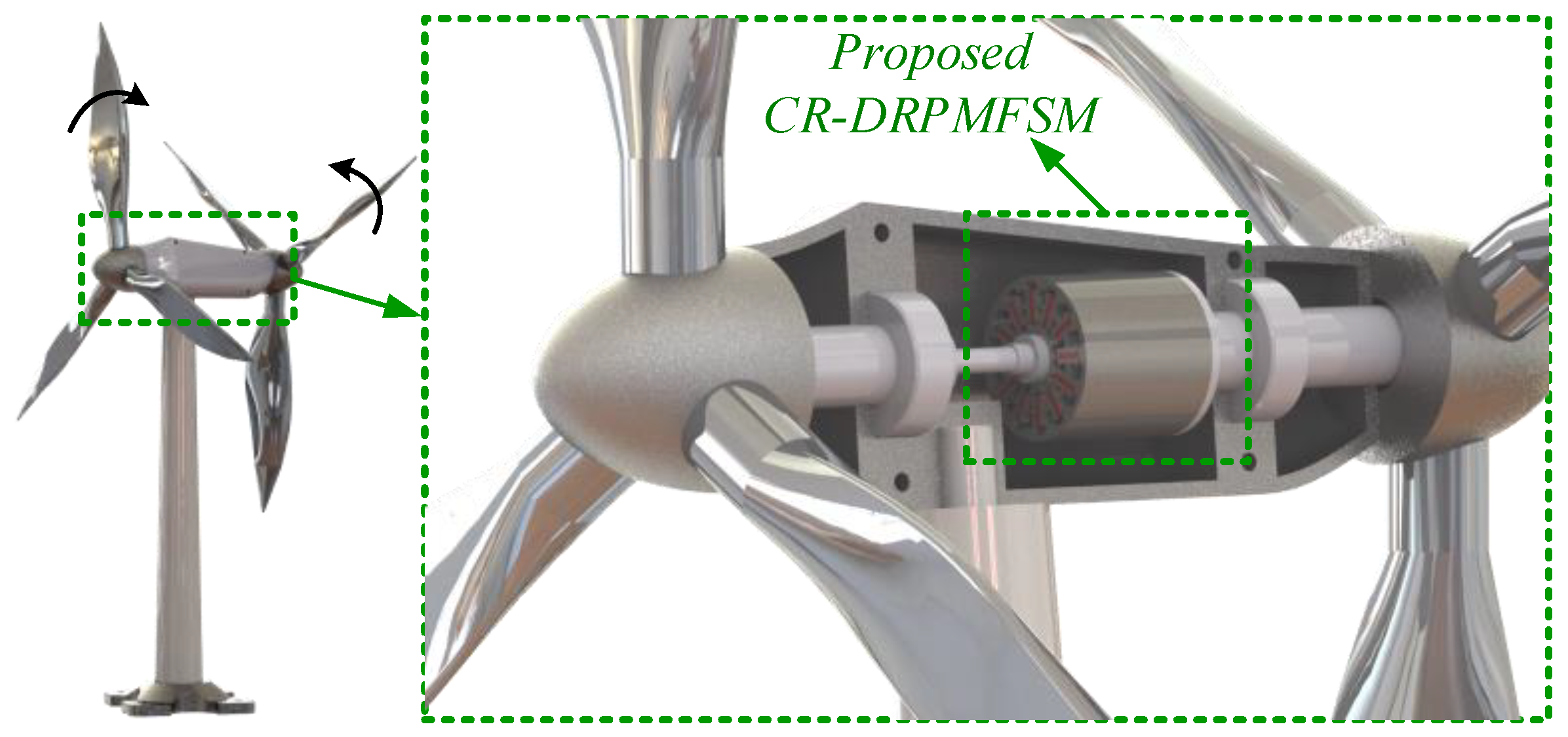
2.1. Direct Drive Counter-Rotating Wind Power Generation
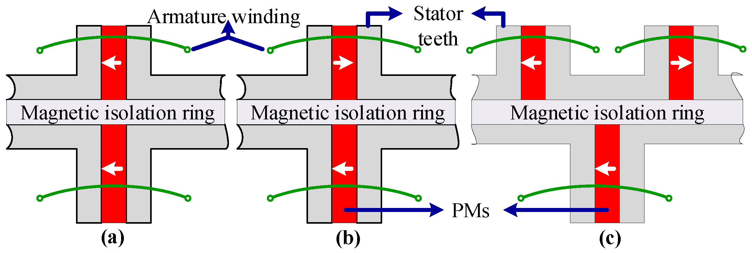
2.2. Magnetization Concept for Series and Parallel Stator Teeth
3. Results and Discussion
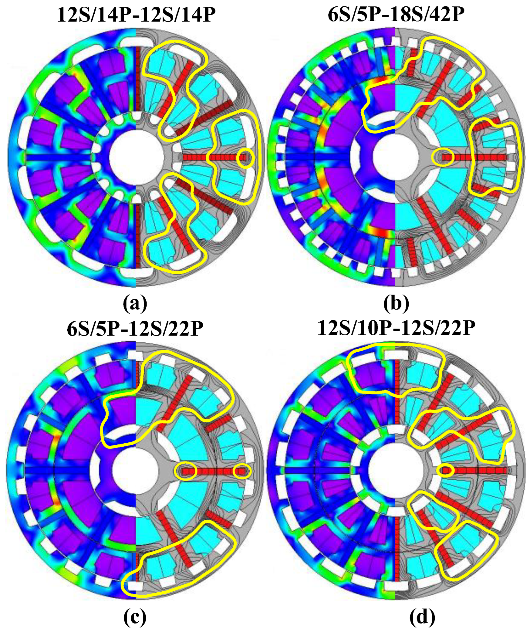
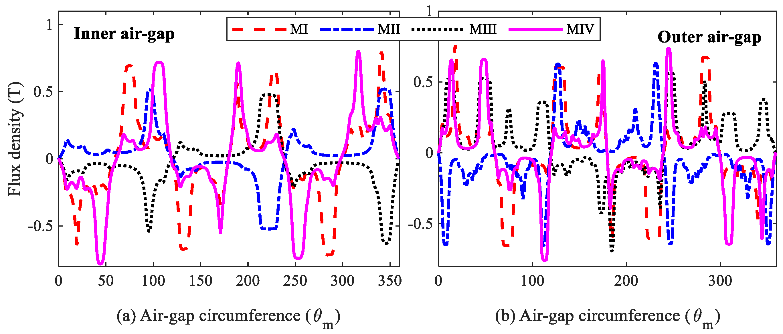
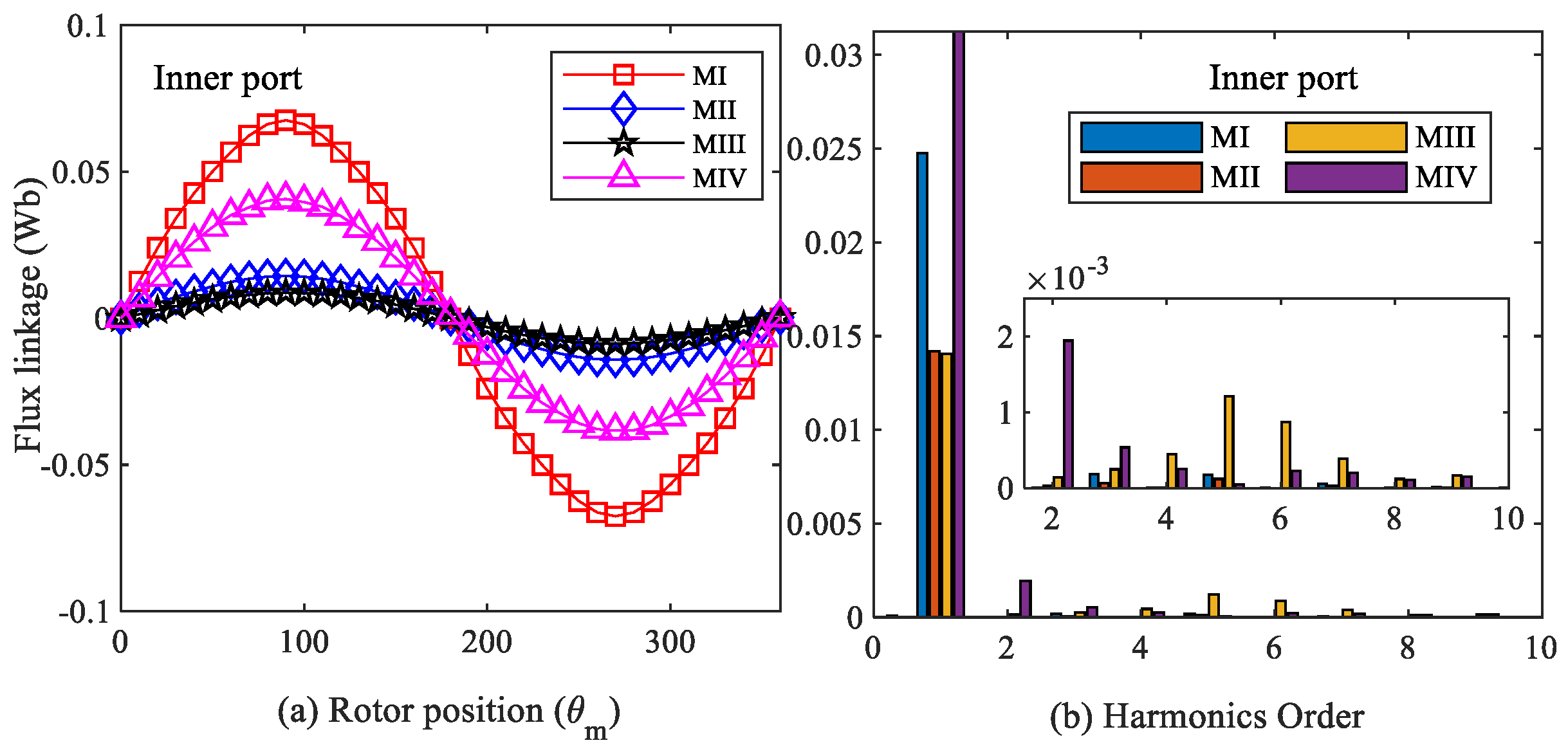
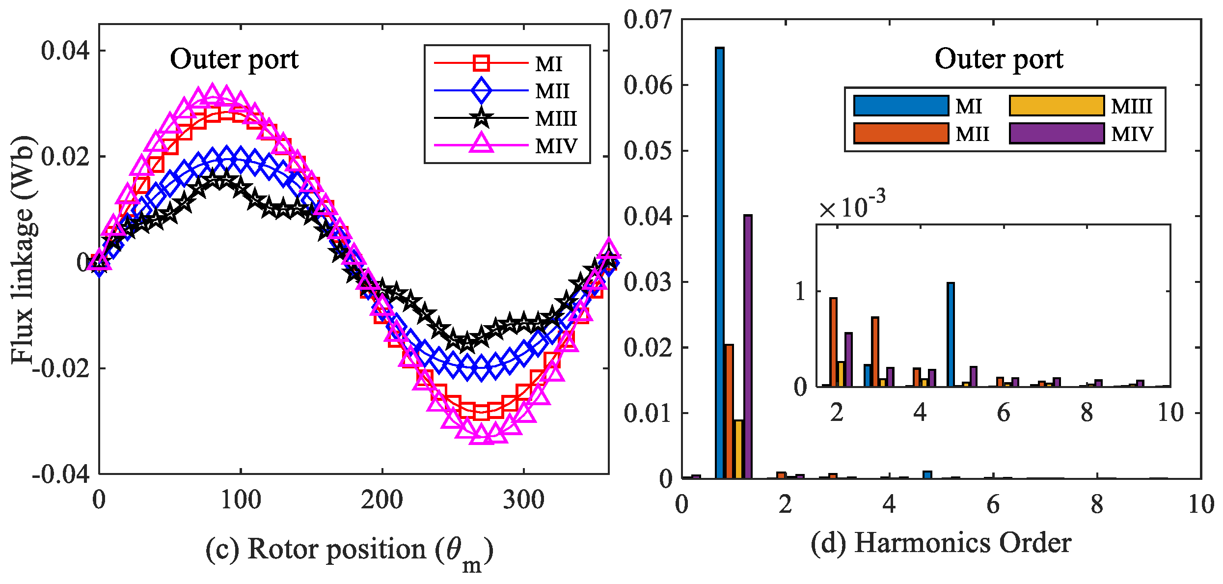
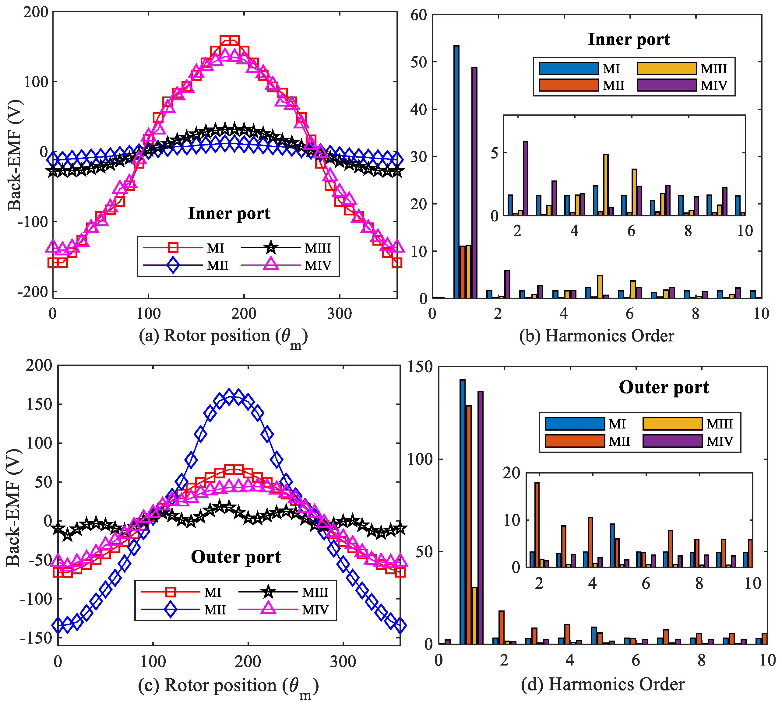
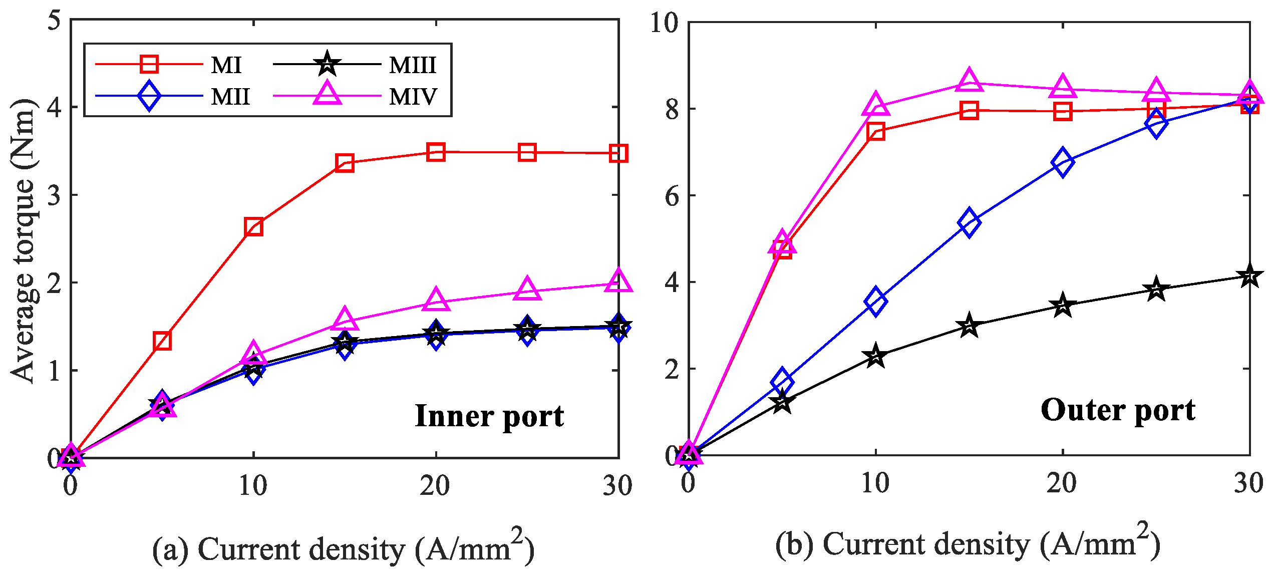
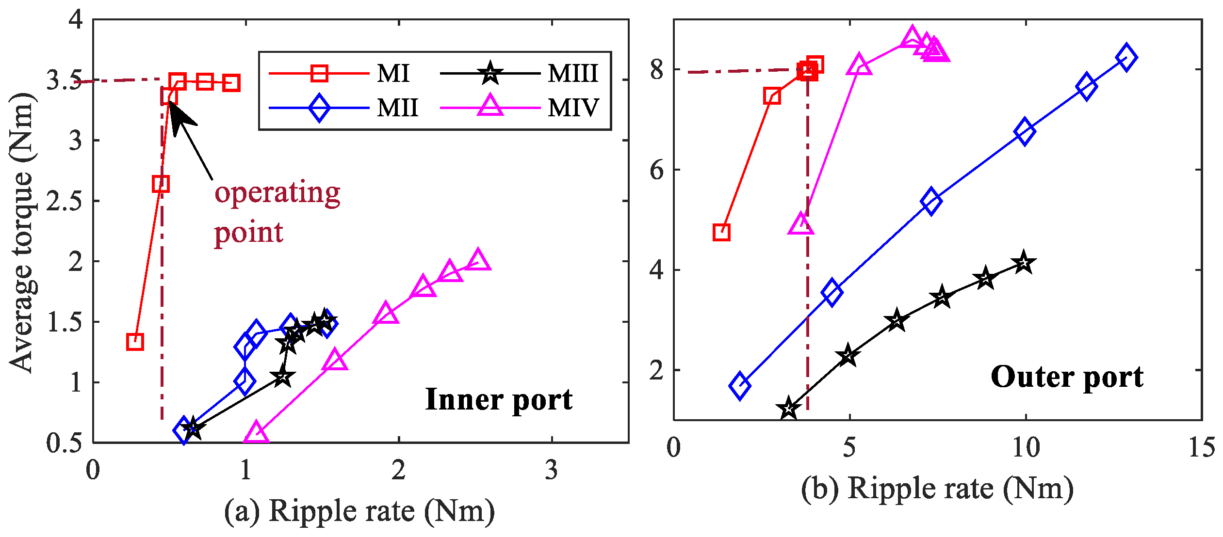
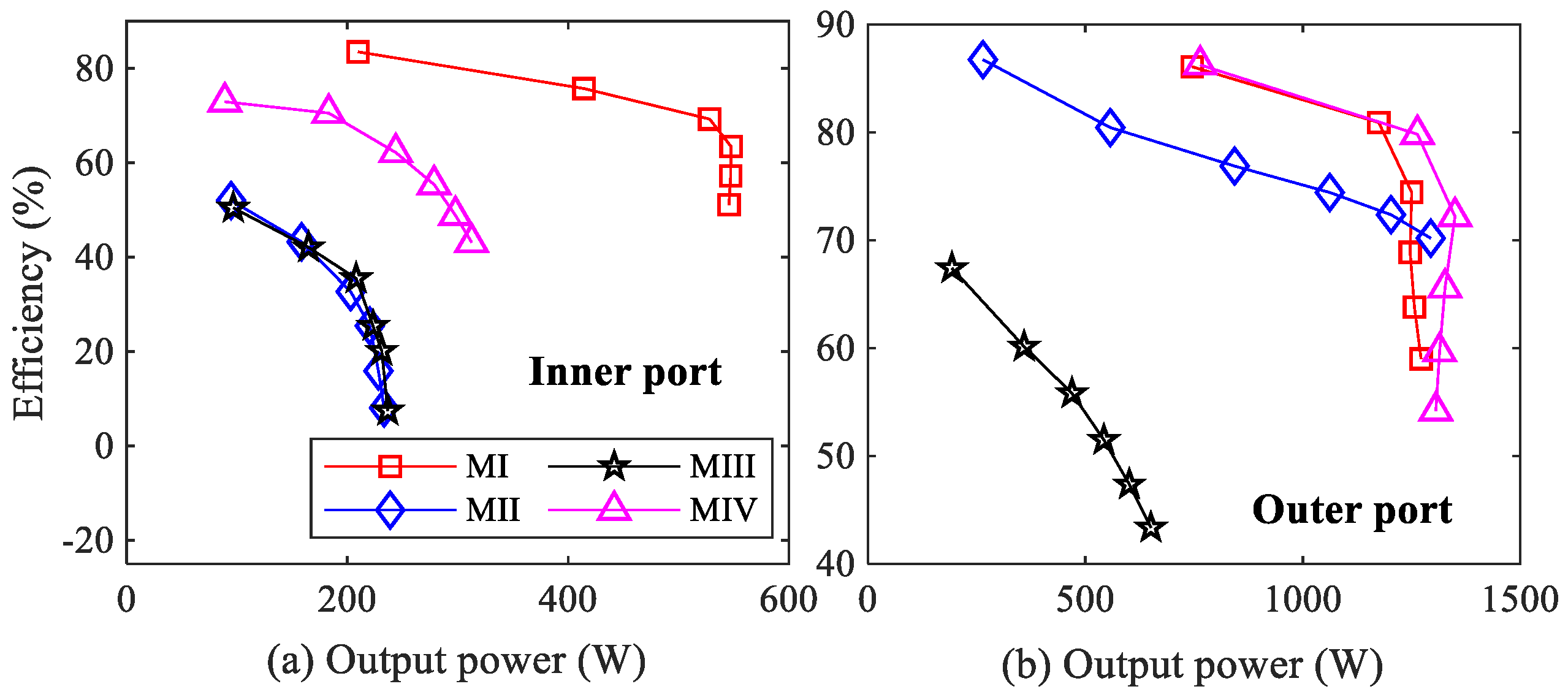
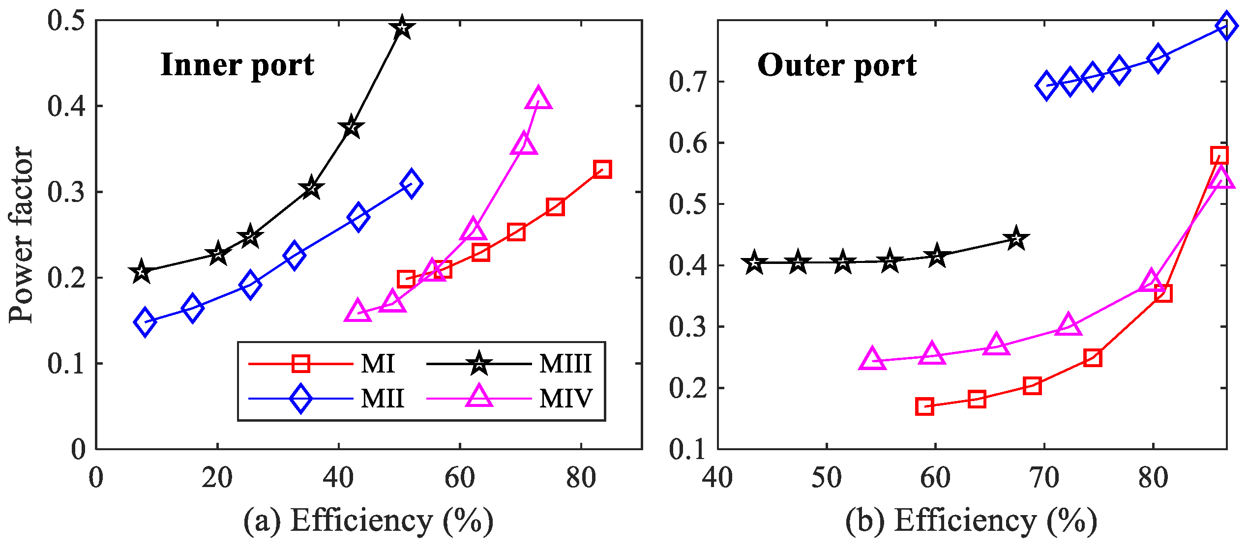
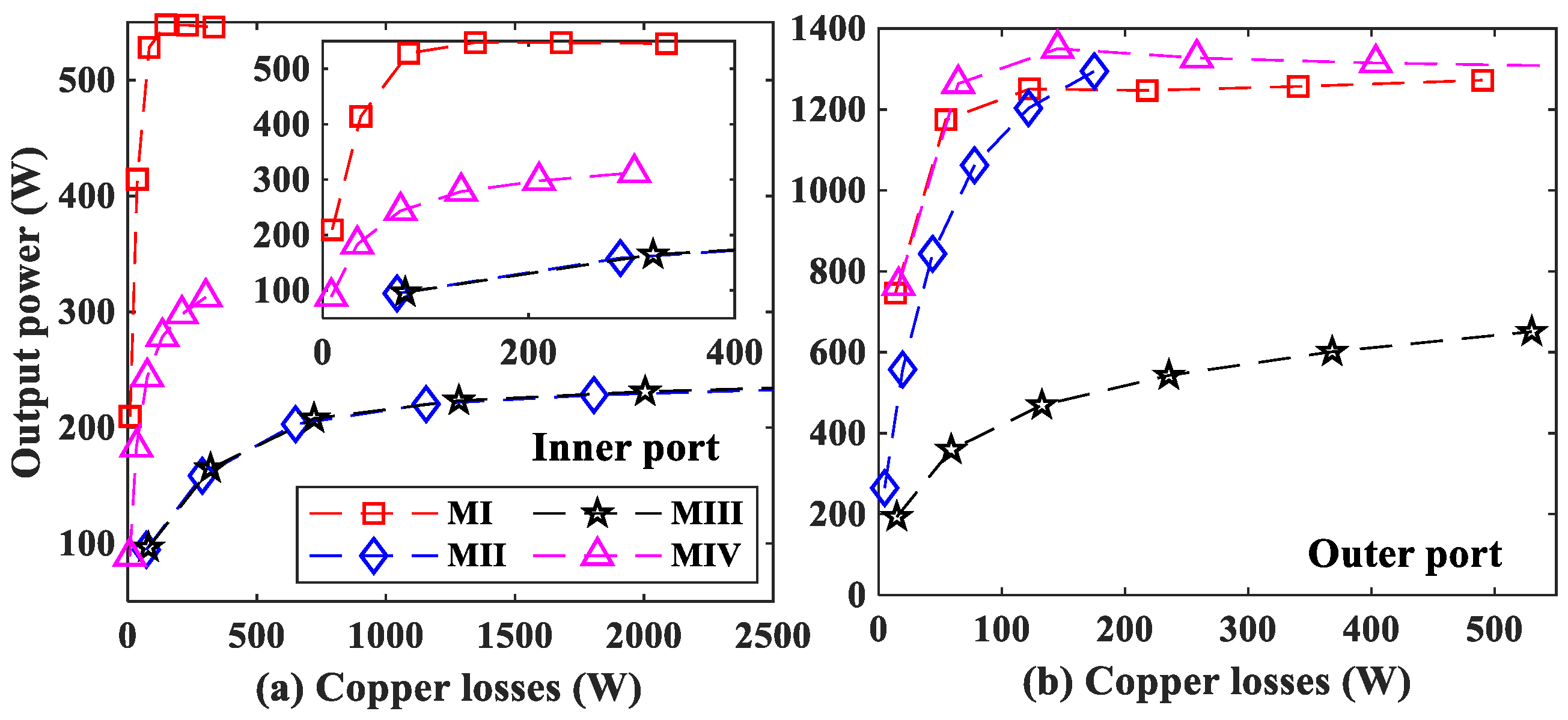
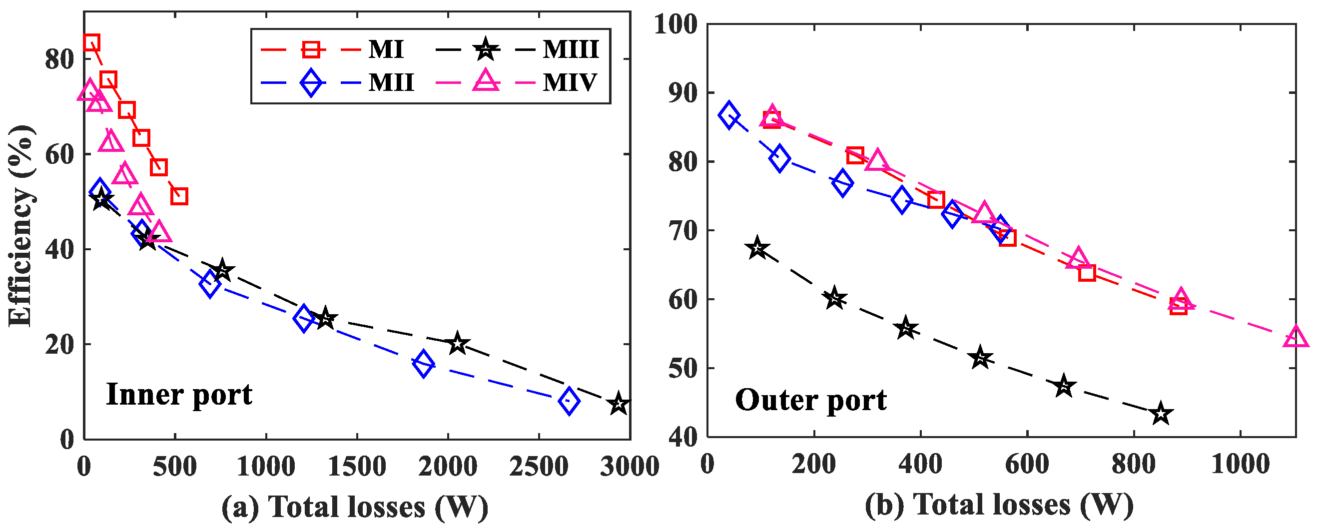
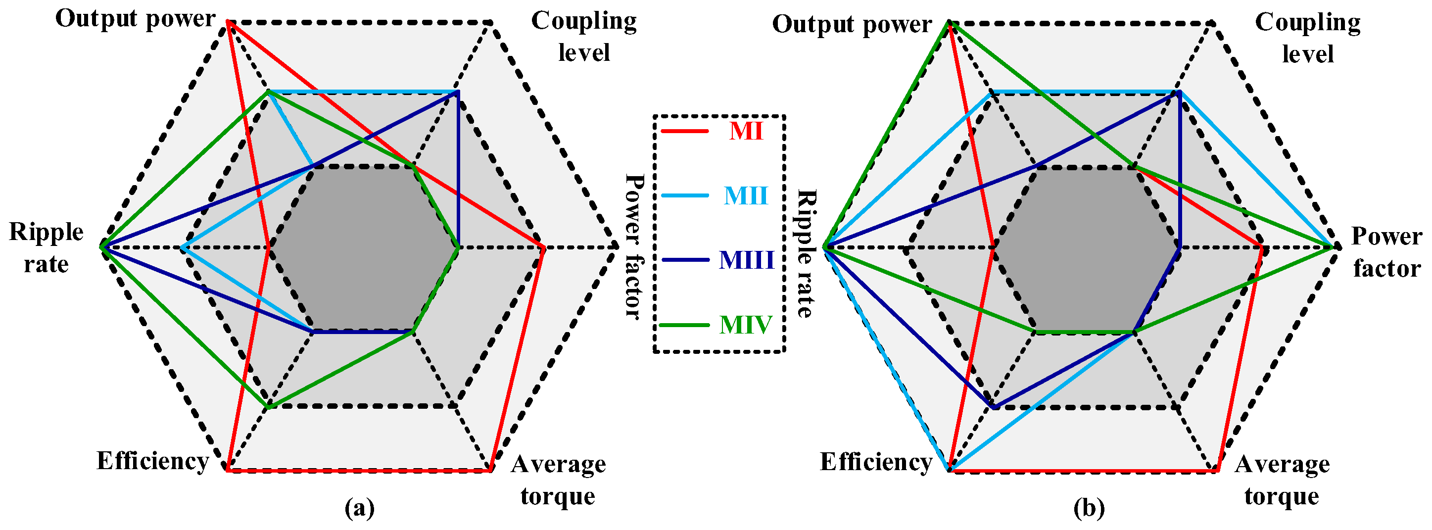
3.1. Electromagnetic Performance Analysis
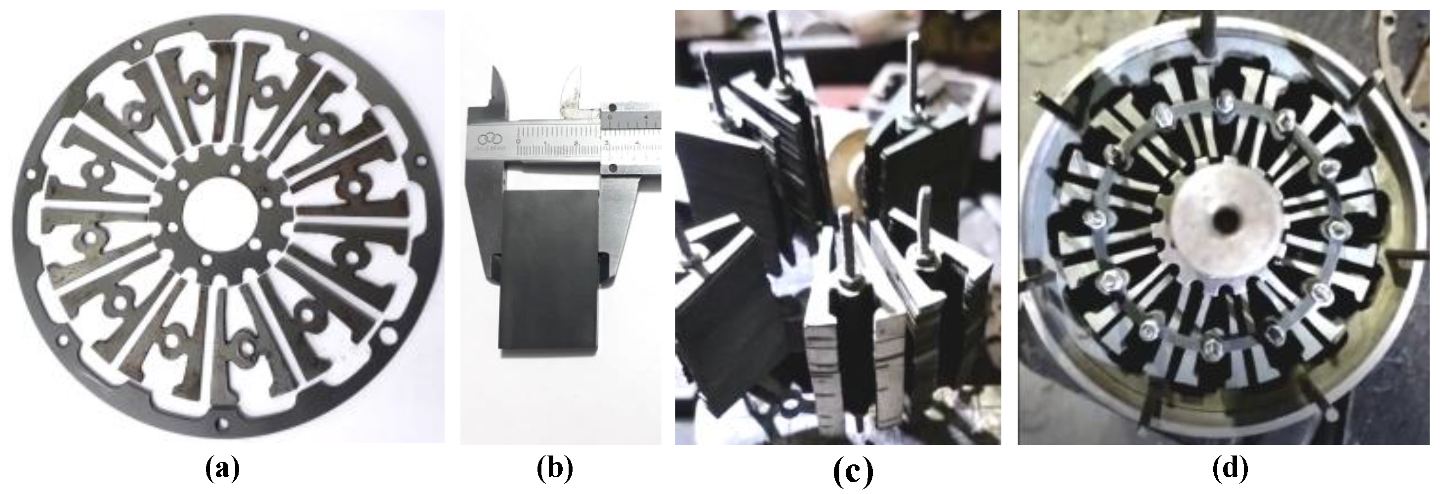
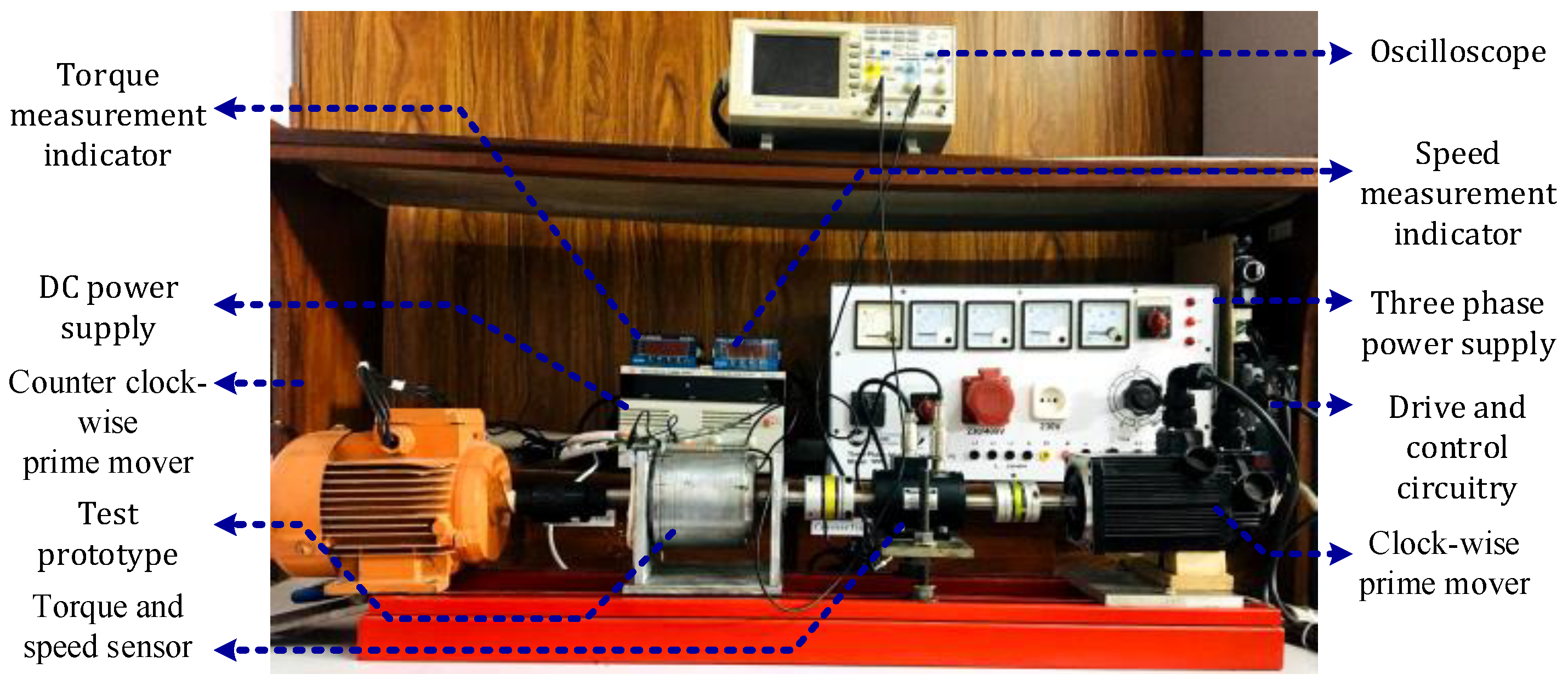
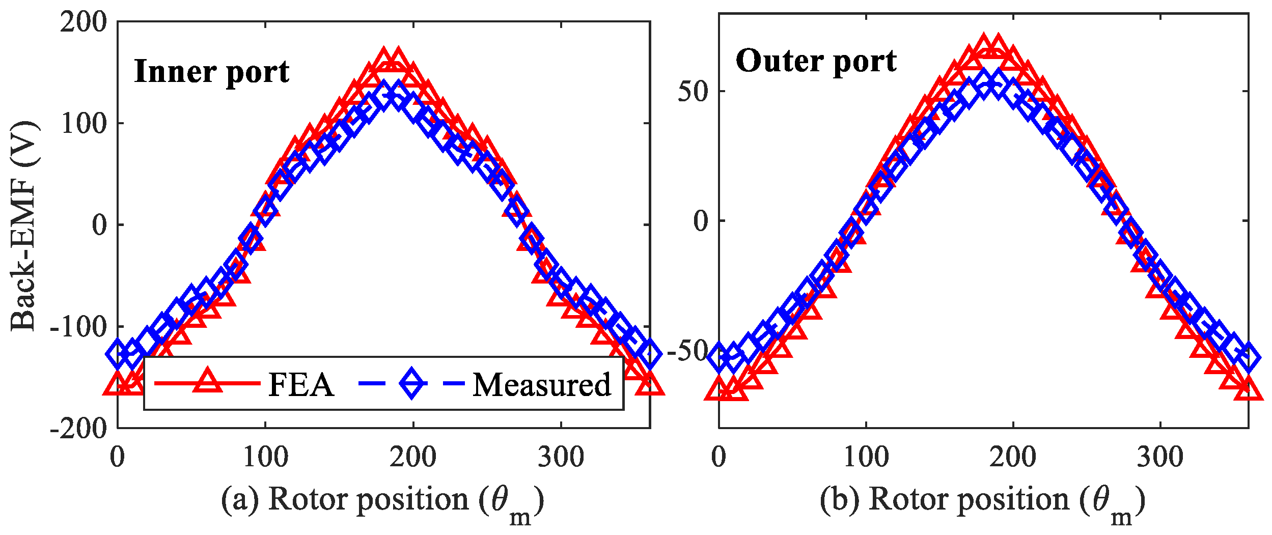
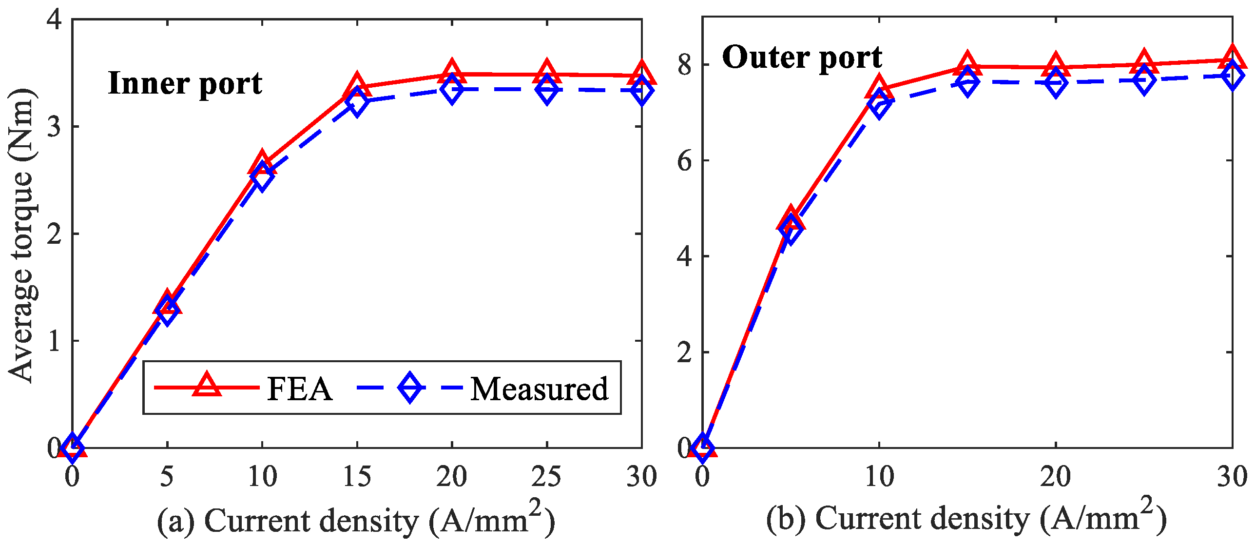
3.2. Experimental Verification
4. Conclusions
Author Contributions
Funding
Data Availability Statement
Conflicts of Interest
References
- Ullah, W.; Khan, F.; Hussain, S. Investigation of Inner/Outer Rotor Permanent Magnet Flux Switching Generator for Wind Tur-bine Applications. IEEE Access 2021, 9, 149110–149117. [Google Scholar] [CrossRef]
- Kwon, J.W.; Kwon, B.I. Design of novel high performance dual rotor flux-switching drum winding machine. J. Electr. Eng. Technol. 2019, 14, 2019–2025. [Google Scholar] [CrossRef]
- Zhao, G.; Li, Z.; Hua, W.; Ding, S.; Su, P.; Jiang, X. Analysis of a Novel Dual-Three-Phase Dual-Rotor Flux-Switching Permanent Magnet Machine. In Proceedings of the IEEE 20th Biennial Conference on Electromagnetic Field Computation (CEFC), Denver, CO, USA, 24–26 October 2022; pp. 1–2. [Google Scholar]
- Wang, Y.; Zhao, W.; Yu, M.; Yang, Y.; Kwon, B.-I. Design and Optimization of a Novel Dual-Stator Flux-Switching Permanent Magnet Machine. In Proceedings of the IEEE 3rd Student Conference on Electrical Machines and Systems (SCEMS), Jinan, China, 4–6 December 2020; pp. 89–93. [Google Scholar]
- Xiang, Z.; Quan, L.; Zhu, X.; Huang, J.; Fan, D. Investigation of Optimal Split Ratio in Brushless Dual-Rotor Flux-Switching Permanent Magnet Machine Considering Power Allocation. IEEE Trans. Magn. 2018, 54, 8102104. [Google Scholar] [CrossRef]
- Yu, C.; Niu, S.; Ho, S.L.; Fu, W.N. Design and analysis of a magnetless double-rotor flux switching motor for low cost application. IEEE Trans. Magn. 2014, 50, 8105104. [Google Scholar] [CrossRef]
- Selema, A. Development of a Three-Phase Dual-Rotor Magnetless Flux Switching Generator for Low Power Wind Turbines. IEEE Trans. Energy Convers. 2020, 35, 828–836. [Google Scholar] [CrossRef]
- Saeed, M.S.; Mohamed, E.E.; Sayed, M.A. Design and analysis of dual rotor multi-tooth flux switching machine for wind power generation. In Proceedings of the 2016 Eighteenth International Middle East Power Systems Conference (MEPCON), Cairo, Egypt, 27–29 December 2016; pp. 499–505. [Google Scholar]
- Li, X.; Liu, S.; Wang, Y. Design and Analysis of a New HTS Dual-Rotor Flux-Switching Machine. IEEE Trans. Appl. Supercond. 2017, 27, 5200605. [Google Scholar] [CrossRef]
- Zhao, X.; Niu, S.; Fu, W. Design of a novel parallel-hybrid-excited dual-PM machine based on armature harmonics diversity for electric vehicle propulsion. IEEE Trans. Energy Con. 2019, 66, 4209–4219. [Google Scholar] [CrossRef]
- Hassannia, A. Conceptual design of fractional slot concentrated winding dual-rotor double-speed synchronous motor. IEEE Trans. Energy Convers. 2020, 35, 986–993. [Google Scholar] [CrossRef]
- Du, J.; Xue, Y.; Yang, X. Modeling and inner–outer decoupling of dual-rotor machines for continuous variable transmission systems. IEEE Trans. Ind. Electron. 2017, 64, 8472–8483. [Google Scholar] [CrossRef]
- Xiang, Z.; Lu, Z.; Zhu, X.; Jiang, M.; Fan, D.; Quan, L. Research on magnetic coupling characteristic of a double rotor flux-switching PM machine from the perspective of air-gap harmonic groups. IEEE Trans. Ind. Electron. 2022, 69, 12551–12563. [Google Scholar] [CrossRef]
- Zhou, L.; Hua, W. Influences of stator teeth number on PM coupling levels of co-axial dual-mechanical-port flux-switching PM machines. IEEE Trans. Magn. 2019, 55, 1–7. [Google Scholar] [CrossRef]
- Ullah, W.; Khan, F.; Akuru, U.B.; Yousuf, M. Magnetic Coupling Effect and Performance Analysis of Dual Rotor Permanent Magnet Flux Switching Generator for Counter Rotating Wind Power Generation. IEEE Trans. Energy Convers. 2023, 1–13. [Google Scholar] [CrossRef]


| Refs. | Winding | Shortcomings and Comments |
|---|---|---|
| [2] | Drum winding | Mechanically coupled rotor and, therefore, counter rotation is not possible. Mutual coupling effect exists but is not analyzed. |
| [6] | Concentrated toroidal winding | Pancake structure and, therefore, is not feasible for counter rotation. Integral rotor structure by mechanically coupling of inner and outer rotor with end disc |
| [7] | Group concentrate for armature winding and toroidal winding for field excitation | Mechanically coupled rotor and, therefore, counter rotation is not possible. Due to group winding, the magnetic path formed is longer. As a result of armature winding groups, the mutual effect is higher. |
| [9] | Toroidal field winding Armature winding overlapped field coils | Modular segmented stator creates manufacturing complexity. High-temperature superconductor (HTS) winding is adopted and, therefore, requires cryogenic cooling. |
| Torque Density (Nm/kg) | Power Density (kW/kg) | |||||
|---|---|---|---|---|---|---|
| Inner Machine | Outer Machine | Cumulative | Inner Machine | Outer Machine | Cumulative | |
| MI | 9.3 | 22.11 | 31.41 | 1.47 | 3.47 | 4.94 |
| MII | 6.64 | 27.62 | 34.26 | 1.046 | 4.35 | 5.396 |
| MIII | 6.80 | 14.89 | 21.69 | 1.071 | 2.419 | 3.49 |
| MIV | 4.30 | 23.86 | 28.16 | 0.67 | 3.75 | 4.42 |
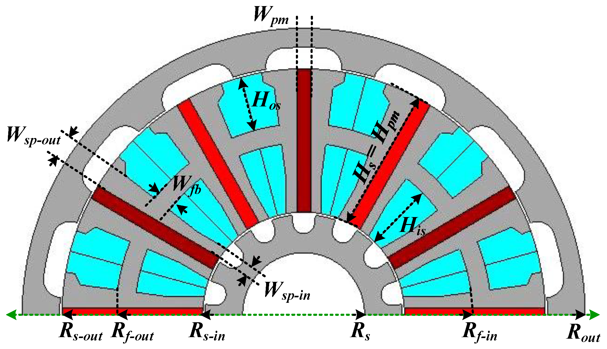
| Symbol | Value (mm) | Symbol | Value (mm) | Symbol | Value (mm) |
|---|---|---|---|---|---|
| 60 | 51.5 | 41 | |||
| 35 | 21.5 | 13 | |||
| 2.26 | 3.75 | 6 | |||
| 13.5 | 10.5 | 30 | |||
| 30 | 4 |
Disclaimer/Publisher’s Note: The statements, opinions and data contained in all publications are solely those of the individual author(s) and contributor(s) and not of MDPI and/or the editor(s). MDPI and/or the editor(s) disclaim responsibility for any injury to people or property resulting from any ideas, methods, instructions or products referred to in the content. |
© 2023 by the authors. Licensee MDPI, Basel, Switzerland. This article is an open access article distributed under the terms and conditions of the Creative Commons Attribution (CC BY) license (https://creativecommons.org/licenses/by/4.0/).
Share and Cite
Ullah, W.; Khan, F.; Akuru, U.B.; Khan, B.; Khalil, S.A. Evaluation of Counter-Rotating Dual-Rotor Permanent-Magnet Flux-Switching Machine with Series and Parallel Stator Teeth. Machines 2023, 11, 989. https://doi.org/10.3390/machines11110989
Ullah W, Khan F, Akuru UB, Khan B, Khalil SA. Evaluation of Counter-Rotating Dual-Rotor Permanent-Magnet Flux-Switching Machine with Series and Parallel Stator Teeth. Machines. 2023; 11(11):989. https://doi.org/10.3390/machines11110989
Chicago/Turabian StyleUllah, Wasiq, Faisal Khan, Udochukwu Bola Akuru, Bakhtiar Khan, and Salar Ahmad Khalil. 2023. "Evaluation of Counter-Rotating Dual-Rotor Permanent-Magnet Flux-Switching Machine with Series and Parallel Stator Teeth" Machines 11, no. 11: 989. https://doi.org/10.3390/machines11110989