
Vibration Characteristics of Asymmetric Flexible Cantilever Beams Connected to a Central Rigid Body


1
Key Laboratory of Operation Safety Technology on Transport Vehicles, Ministry of Transport, Beijing 100088, China
2
College of Aerospace and Civil Engineering, Harbin Engineering University, Harbin 150001, China
*
Author to whom correspondence should be addressed.
Machines 2024, 12(3), 193; https://doi.org/10.3390/machines12030193
Submission received: 20 January 2024
/
Revised: 1 March 2024
/
Accepted: 13 March 2024
/
Published: 15 March 2024
(This article belongs to the Section Machine Design and Theory)
Abstract
:A satellite with two solar wings can be modeled using a pair of symmetric flexible cantilever beams connected to a central rigid body. Due to certain reasons, the symmetric flexible cantilever beams may be turned into asymmetric ones, which will inevitably influence the vibration properties of the structural system. By changing the structural sizes and adding local mass on one side of the two beams, a structural system with asymmetric mass distribution is obtained and its vibration characteristics are investigated. Hamilton’s principle with the assumed mode method is employed to establish the equation of motion of the asymmetric structural system. The natural frequencies, mode shapes, frequency response curves and displacement time histories of the system are calculated, and they are compared with those of the structural system with a symmetric mass distribution. The correctness and feasibility of the present analytical method are verified by means of the finite element method (FEM) and a vibration experiment. The analytical results show that the mass asymmetry of the two beams leads to the mode localization phenomenon, and the coupling effect between the two beams and the central rigid body is enhanced. The larger the mass asymmetry is and the closer the position of the added local mass to the end of the cantilever beam is, the more obvious of the mode localization phenomenon is and the more obvious of the coupling effect between the two beams and the central rigid body is. The present investigation results are helpful for the dynamic analysis and design of spacecraft structures composed of flexible solar wings and a central rigid body.
1. Introduction
Because of the small sizes of the flexible appendages of early spacecraft, their impacts on the main body of the spacecraft were generally negligible, and they were often regarded as simple flexible cantilever beams or cantilever plate structures [1,2]. In recent years, studies have shown that with the appendages of spacecraft becoming more and more large and flexible, the structural vibrations of the flexible appendages will have an effect on the main body of spacecraft, and the motion of the main body of spacecraft will be able to react on the flexible appendages, which will result in the occurrence of a rigid–flexible coupling effect. The rigid–flexible coupling effect has also become the focus and difficulty of investigations on the dynamics of spacecraft with flexible appendages [3,4].
Currently, the majority of research on rigid–flexible coupling focuses on the coupling between a single flexible appendage and the main body of a spacecraft. Gao et al. [5] simplified the satellite antenna system as a cantilever beam connected to a central rigid body, and studied its nonlinear dynamic characteristics by using the assumed mode method and the method of multiple scales. Azimi and Joubaneh [6] realized the dynamic modeling of a high-order spacecraft system with a flexible panel, and suppressed its responses under loads with different frequencies through piezoelectric plates. In addition, the vibration of spacecraft with a flexible appendage in the rotating state is also a long-term research focus. Yoo and Shin [7] put forward the coupling analysis method for axial and bending motions of rotating beams, and found that when the rotating speed exceeds a certain value, the natural frequencies and mode shapes of the beam change obviously. Yang et al. [8] used the finite element method (FEM) to model a rotating Euler–Bernoulli beam considering the centrifugal stiffening effect, and designed a control algorithm to suppress the transverse vibration of the rotating beam. Tian et al. [9] studied the influence of the Coriolis effect on the vibration behavior of rotating beams by using a modified variational method, and found that the Coriolis effect can be ignored when the rotating angular velocity is low. The above researches show that centrifugal force and the Coriolis effect must be considered for a flexible spacecraft rotating at high speed, but it is also feasible to consider only the transverse vibration of flexible appendages for spacecraft with solar wings in static operation.
In fact, the solar wings on both sides of most spacecraft are symmetrical, so it is difficult to fully reflect the characteristics of the whole system only by analyzing the coupling between a single solar wing and the main body of the spacecraft. Some investigations on the rigid–flexible coupling effect of spacecraft with two symmetric solar wings have been conducted. Cao et al. [10] used the global mode method to study the vibration characteristics of a three-axis stabilized spacecraft with symmetric solar wings, and found that the flexible solar wings on both sides will vibrate symmetrically or antisymmetrically under certain conditions. Xing and Wang [11] analyzed the vibration characteristics of a spacecraft with double-direction hinged solar arrays, and found that the moment of inertia of the central rigid body and the aspect ratio of the solar arrays make the system appear with frequency veering and mode shift phenomena. Obviously, the vibration behaviors of a spacecraft with symmetrical flexible appendages are more complicated than those of a spacecraft with only a single appendage, so it is necessary to conduct more research on the former.
In theory, the two solar wings on either side of the spacecraft should perfectly be symmetrical structures. However, in reality, this may not always be the case due to defects in the materials, errors made during manufacturing and processing, wear and tear, etc., which cause the sizes, masses, stiffnesses, etc., of the two solar wings of the spacecraft to be different from each other. This phenomenon is known as disorder, i.e., real conditions deviating from the ideal ones [12,13,14]. Investigations have demonstrated that the dynamical properties of disordered systems create considerable changes due to the asymmetry of the structures, and many researchers have carried out studies on the vibration properties of disordered periodic structures [15,16,17,18]. Laxalde and Pierre [19] established the reduced-order dynamics model for multi-stage disordered cyclic symmetric bladed disk assemblies, explored the modal localization properties of the disordered bladed disk, and analyzed the influence of the disorder degree on the sensitivity of the bladed disk. Zhou et al. [20] investigated the vibration characteristics of disordered two-span beams, and established the structural dynamics model by using the modal superposition method. They explored the effects of the disorder degree on the free and forced vibrations of the disordered two-span beams. In addition, further investigation results have been published in this regard [21,22,23,24].
The above analysis reveals that, at present, an increase in research on mode localization focuses on structural stiffness or dimension disorder, with a notable scarcity of studies on the vibration localization characteristics of structural mass disorder or, in cases of lumped mass, on the structure. However, some studies show that the local perturbation caused by lumped mass obviously influence the vibration characteristics of structures, such as by changing the natural frequencies of plates [25] or suppressing the energy of elastic waves in beams [26]. Consequently, this study delves into the influence of mass asymmetry on the vibration properties of satellites with two solar wings, which can be modeled as a pair of symmetric flexible cantilever beams connected to a central rigid body. By utilizing Hamilton’s principle and the assumed mode method, the equation of motion of the system with an added local mass on one side of the two beams is established. By altering the size of the cantilever beam on one side of the two beams, the vibration properties of the system with mass disorder due to the size deviation are studied. By adding a lumped mass on the different positions of one beam, the impact of local mass disorder on the vibration properties of the system is explored. The FEM software COMSOL Multiphysics 6.0 and a vibration experiment are employed to confirm the correctness of the outcomes of the theoretical analysis.
2. Establishment and Solution of Structural Equation of Motion
2.1. Establishment of Equation of Motion
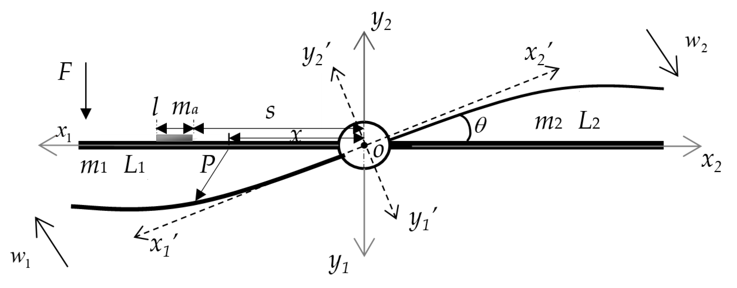
The research object is a central rigid body connected with asymmetric flexible cantilever beams, as shown in Figure 1. The Cartesian coordinate system is also displayed in Figure 1, where o-x1y1 and o-x2y2 are inertial coordinate systems describing the motion of two beams, respectively, and o-x1′ y1′and o-x2′y2′ are floating coordinate systems after angular displacement of θ. The bending vibrations of the cantilever beams on both sides of the central rigid body are considered. Both cantilever beams are Euler–Bernoulli beams with lengths L1 and L2, and line densities m1 and m2. A lumped mass with length l and line density ma is attached to one side of the two beams to simulate the disordered local lumped mass on the solar wing. The distance of the lumped mass from the coordinate origin is s.
The motion of the system shown in Figure 1 consists of two parts. The first part is the rigid attitude rotation, θ, driven by the central rigid body together with the two cantilever beams on both sides, and the second part is the bending vibration, w(x, t), of each of the two cantilever beams. Therefore, the system is a rigid-flexible coupled dynamical system. Hamilton’s principle and the assumed mode method can be used to establish the dynamic equation of the system.
To use the assumed mode method, the attitude angle, θ, of the system and the bending vibration displacements w1 and w2 of the beams on both sides are written in the forms of products of mode shape functions and generalized coordinates, and they can be written as follows [27,28]:
where , and are the generalized coordinates corresponding to the attitude rotation and bending vibrations of the beams, is the angular mode constant, and and are the mode shape functions of the cantilever beams, which can be expressed as follows:
where is the ith characteristic root corresponding to the characteristic equation of a cantilever beam during bending vibration, which is denoted by , and for .
Let the global modal generalized coordinate vector of the system be as follows:
Then, the three parts of the motion of the system in Equation (1) can be expressed as follows:
in which
Taking the left beam as an example, when deformation occurs, the position vector of any point, P, on the beam in the coordinate system, o-x1y1, can be written as follows:
in which
where R is the direction cosine matrix of the floating coordinate system relative to that of the inertial coordinate system.
The velocity of point P in the inertial coordinate system can be expressed as follows:
Similarly, it can be concluded that the velocity, , of the point on the right beam takes the same form as the above formula.
The kinetic energy of the system consists of four components, i.e., the rotational kinetic energy of the central rigid body, the kinetic energies of the two cantilever beams, and the kinetic energy of the lumped mass. The expression for the total kinetic energy of the system is given as follows:
Because the mass of the central rigid body is much larger than that of the flexible beams on both sides, the motions of the flexible attachments create little disturbance to the central rigid body, so it can be considered that the value of θ is very small. Since only the small linear bending vibrations of the flexible beams are considered, we can let and , and ignore the high-order small variables; then, the expression of kinetic energy can be expanded as follows:
where is the rotational inertia of the center rigid body, and M is the total mass matrix of the system, which consists of four parts: the mass matrix M0 corresponding to attitude rotation, the mass matrices M1 and M2 relating to the left and right beams, and the lumped mass matrix Ma. The specific expressions of these mass matrices are written as follows:
where is the total rotational inertia of the system.
Since the length, l, of the lumped mass is very small compared to that of the cantilever beam, the change in the stiffness of the cantilever beam caused by the lumped mass is neglected. Consequently, the potential energy of the system consists of three parts: the torsional potential energy of the central rigid body, and the bending deformation energies of the two cantilever beams. The expression for the potential energy of the system is given as follows:
where is the torsional stiffness of the central rigid body, and denote the bending stiffnesses of the left and right beams, and K is the total stiffness matrix of the system, which consists of three parts: the torsional stiffness matrix K0 of the central rigid body, and the bending stiffness matrices K1 and K2 of the two beams. The specific expressions of these matrices are written as follows:
Since the added lumped mass is relatively light, its energy dissipation is not considered. Whereas the central rigid body is often subjected to a control term with damping characteristics when it rotates, it can be assumed that the energy dissipated by the whole system mainly originates from the central rigid body, i.e.,
where cθ is the damping coefficient, and D is the energy dissipation function that represents the work carried out by the damping force during the vibration of the system.
Assuming that an external force, F, is applied on the left beam at x0, the virtual work done by the external force F is
where Q is the generalized force vector.
Substituting the kinetic energy, , the potential energy, , and the virtual work of the external force, , into Hamilton’s principle [27,29,30],
and introducing the damping term due to the rotation of the central rigid body, the equation of motion of the system can be obtained as follows:
where is the damping matrix.
2.2. Theoretical Solutions
2.2.1. Forced Vibration
For a simple harmonic excitation, , Equation (17) can be expressed as follows:
in which , and Q0 is the generalized force amplitude vector, which can be determined by replacing F in Equation (15) with F0.
The steady solution of Equation (18) can be expressed as follows:
where A is the amplitude. Substituting Equation (19) into Equation (18) leads to the following:
from which the amplitude, A, can be calculated. Then, substituting A into Equation (19), the generalized coordinates can be obtained, and the frequency response curve of each point on the structure can be finally calculated from Equation (4).
2.2.2. Free Vibration
For free vibration, Equation (18) is simplified as follows:
The above equation is a homogeneous one, the general solution of which can be written as follows:
where q0 is the eigenvector and λ is the eigenvalue.
Substituting Equation (22) into Equation (21) yields the following:
The condition for the existence of nonzero solutions is that the coefficient determinant of the above equation is zero, i.e.,
Solving the above equation yields the eigenvalue of the structural system, and the imaginary part of the eigenvalue is the natural frequency of the structure.
By applying a unit impulse, the generalized coordinates can be obtained by numerically solving Equation (21); then, the free vibration response of the structure can be finally calculated from Equation (4).
3. Validations
3.1. Validation by the FEM
In this subsection, the natural frequencies and mode shapes of the structural system composed of a central rigid body and two asymmetric cantilever beams are computed using the present analytical method and compared with those obtained from the FEM software COMSOL Multiphysics. The material and structural parameters used in the calculations are set to be as follows [9]: the linear density of the two beams is m1 = m2 = 0.03 kg/m, the rotational inertia of the central rigid body is I0 = 1000 kg·m2, the length of the two beams is L1 = L2 =10 m, the torsional stiffness of the whole system is kθ = 500 N·m/rad, the bending stiffness of the two beams is , the length of the lumped mass is s = 0.01 m, and the linear density of the lumped mass is ma = 0.6 kg/m.
For the lumped mass attached at the left end of the left beam, the first seven orders of the natural frequencies of the system are calculated using the present method and the FEM software COMSOL Multiphysics, as shown in Table 1. In COMSOL Multiphysics, the axial displacements of the beams are ignored, and the geometric nonlinear characteristics of the beams are not included. It can be seen that the natural frequencies computed using the present method match very well with those of the FEM. Figure 2 shows the first four mode shapes of the system calculated by using the two methods, and it can be seen from the figure that the results obtained via the two methods are in good agreement, thus proving that the modeling method and calculation program in this paper are feasible.
3.2. Validation via the Vibration Experiment
In this subsection, the vibration experiment is employed to verify the feasibility of the present analytical method. The designed experimental prototype for the central rigid body connected with two flexible cantilever beams is illustrated in Figure 3a, and the experimental setup is shown in Figure 3b. The equipment mainly includes the YE6270 data collector, a data processor, acceleration sensors and a force hammer, which are all made by Sinocera Piezotronics Inc of Jiangsu, China. Among them, the mass of the sensor can simulate the mass disorder of the flexible beam on one side.
The structural and material parameters of the experimental prototype are selected as follows: the length, width and thickness of the beams on both sides of the central rigid body are L = 0.3 m, b = 0.02 m and h = 0.001 m. The material used is steel, the mass density of which is ρ = 7930 , and Young’s modulus of which is E = 194 GPa. The central rigid body is a cylinder with a radius of 0.02 m and a height of 0.05 m, and U-shaped grooves with a thickness of 0.005 m and a width of 0.02 m are attached on both sides of the cylinder to serve as the connectors between the central rigid body and the two beams.
Table 2 presents the first six natural frequencies of the structural system obtained using the present analytical method and from the vibration experiment. It is observed that the natural frequencies between the analytical and experimental methods are relatively well matched. It is also found that the errors between the results of the two methods are relatively large for some orders, which may be due to the material defects, processing errors, measuring accuracy and so on. At the same time, sensors and wires have some mass, and their parameter deviation also have a great influence on the natural frequencies of the system, which is analyzed in detail in Section 4.1.1. In addition, the errors may also be caused by the parameter deviation of the central rigid body, which is discussed in Section 4.1.2. It can be proven that the present analytical method is very effective in exploring the vibration characteristics of asymmetric flexible cantilever beams connected to a central rigid body.
4. Numerical Results and Discussions
4.1. Natural Frequencies and Mode Shapes
4.1.1. Influence of Mass Disorder
For the case of the lumped mass being 0, the natural frequencies of the symmetrical system composed of a central rigid body and two identical cantilever beams are calculated using the present method. By shortening the length of the left beam by 0.5%, 1% and 1.5%, the effect of different mass disorder degrees on the natural frequencies of the system is investigated, and the numerically calculated results are shown in Table 3. It can be seen that with the decrease in the mass of the left beam, the natural frequencies of odd orders gradually increase, and the natural frequencies of even orders have no significant changes except for the second order.
Without changing the dimensions of the left beam, the same lumped mass is attached to the left beam at L/4, L/2, 3L/4 and L. The effect of the position of the lumped mass on the natural frequencies of the system is studied, and the calculation results are shown in Table 4. It can be seen that as the lumped mass is far away from the central rigid body, the natural frequency of each order of the system usually decreases gradually, and the position of the lumped mass has a larger effect on the even-order natural frequencies of the system and a smaller effect on the odd-order natural frequencies. The farther the position of the lumped mass from the central rigid body, the greater the effect of the position of the lumped mass on the natural frequency.
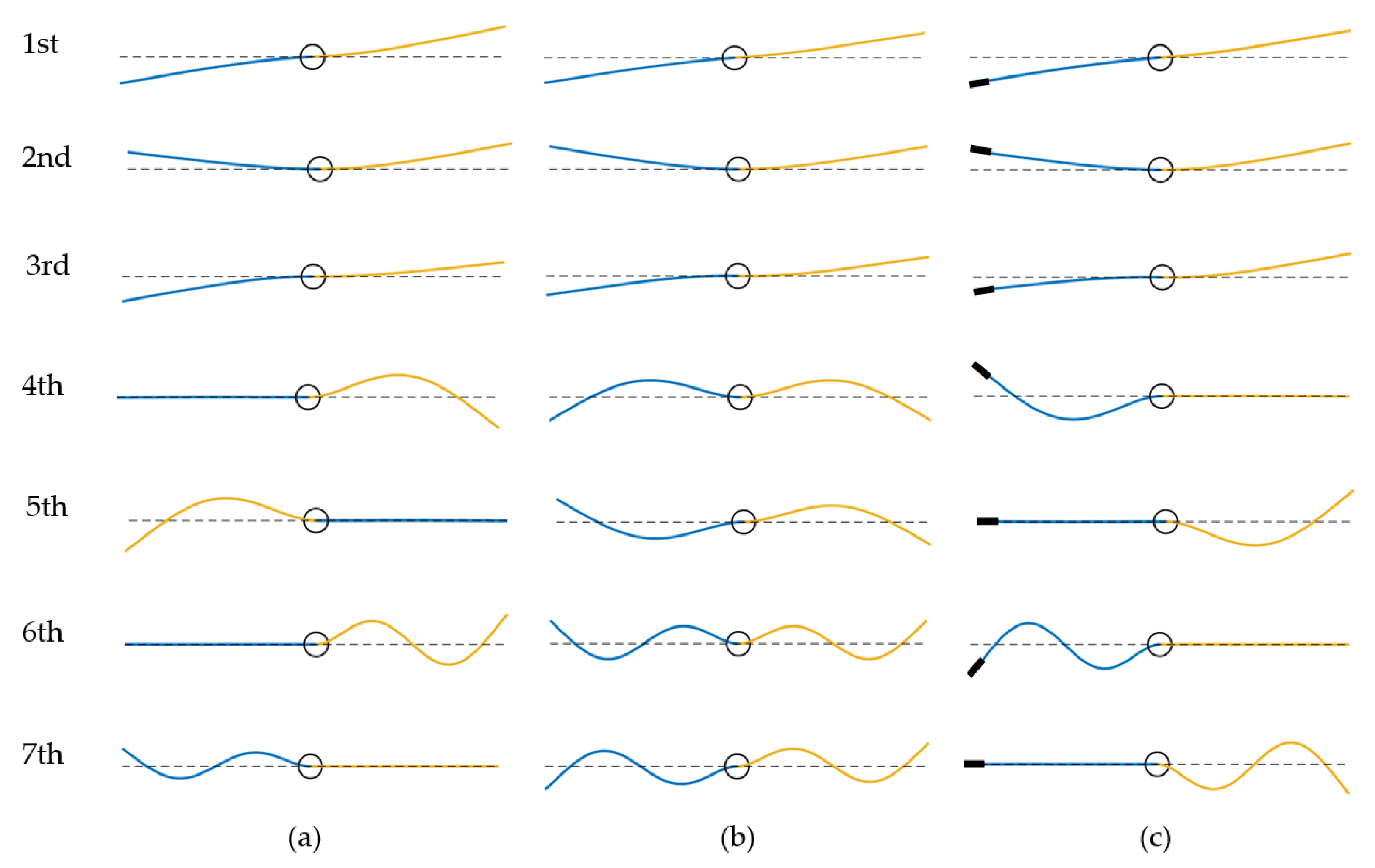
To further analyze the reasons for the change in each order of natural frequency, the first seven mode shapes of the system are given in Figure 4 for both cases of varying the size of the left beam as well as attaching a lumped mass to the left beam, and they are compared with the mode shapes of the symmetrical system composed of a central rigid body and two identical cantilever beams. It is obvious in Figure 4b that the symmetric and antisymmetric mode shapes appear alternately for the symmetrical system. Due to the mass disorder, the mode shapes of the system change significantly. From the fourth-order mode shape, the phenomenon of mode localization occurs, i.e., the mode shapes of the left and right beams being separated. Nevertheless, the mass change of the left beam will not affect the mode shape of the right beam. This explains exactly why the natural frequency of each even order from the fourth order in Table 3 does not change with the increase in mass disorder, and the natural frequency of each odd order from the fourth order in Table 4 does not change with the change in the position of the lumped mass.
4.1.2. Influence of Other Parameters
The effects of the rotational inertia and torsional stiffness of the central rigid body on the natural frequencies of the system are discussed here. As can be seen from Table 5, with the increase in the rotational inertia, the natural frequencies of odd orders of the system decrease, while the natural frequencies of all even orders do not change. It can also be found from Table 6 that with the increase in torsional stiffness, only the natural frequencies of odd orders become larger. It can be concluded that the parameters of the central rigid body affect the antisymmetric bending vibrations of the flexible beams on both sides, but have no effects on the symmetric bending vibrations. Therefore, in the experiment, the errors of some natural frequencies are larger, which is probably caused by the parameter deviation of the central rigid body.
4.2. Forced Vibration
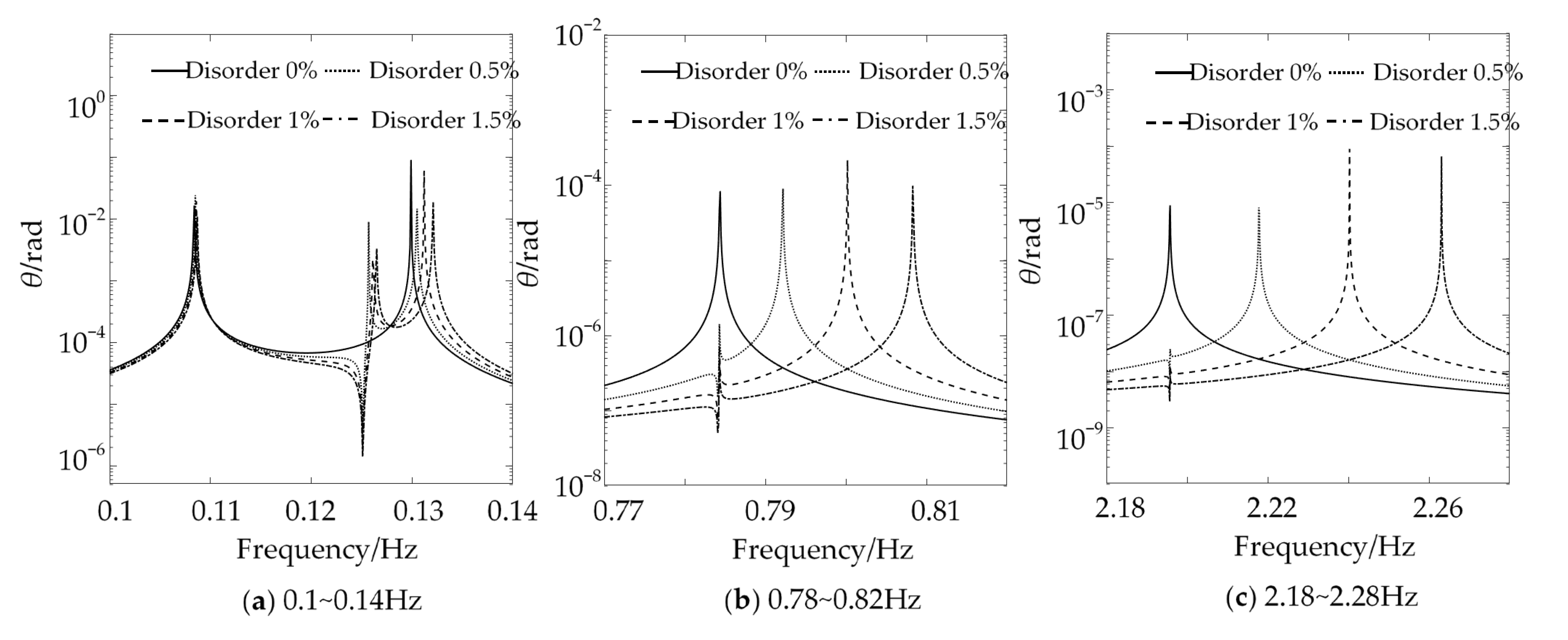
The frequency response curves of the attitude angle of the system under different mass disorders are displayed in Figure 5. In the studied frequency range, the frequency response curves of the attitude angle for the symmetric beams on both sides of the central rigid body have only four peaks, corresponding to 0.1084 Hz, 0.1299 Hz, 0.7843 Hz and 2.1958 Hz. The other three peaks correspond to the antisymmetric bending vibrations of the system, except for the first one, which corresponds to the attitude vibration mode. This is because the attitude rotation of the central rigid body is only affected by the antisymmetric bending vibration of the two beams, and the symmetric bending vibration does not have a coupling effect with the attitude rotation. The mass asymmetry makes the peak numbers of frequency response curves in the attitude angle change from the original four to seven, which is due to the change in the original mode shape of symmetric bending vibration caused by the mass disorder, so that each order of the bending vibration will be coupled with the attitude rotation of the central rigid body, and the larger the degree of mass disorder is, the more obvious the position shift of the new peaks is.
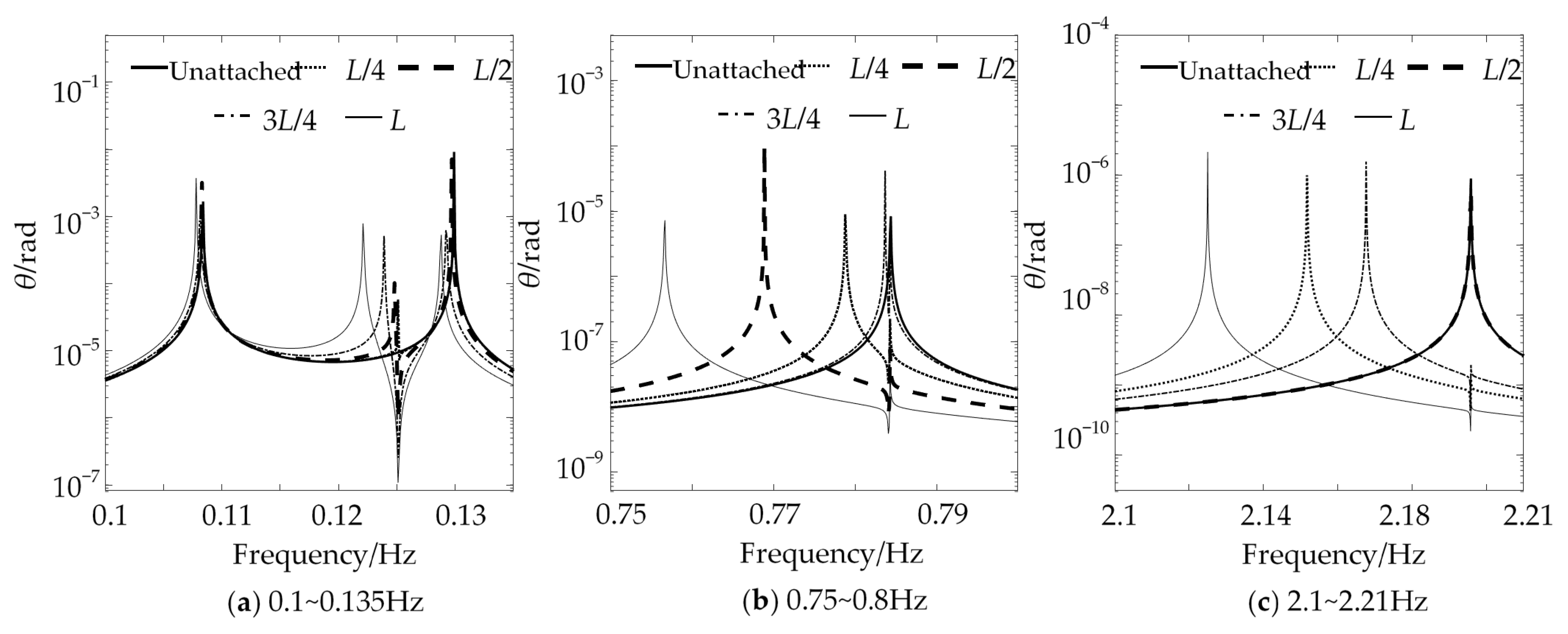
Figure 6 gives the frequency response curves of the attitude angle when the lumped mass is attached at different positions of the left beam, and the peak numbers of frequency response curves of the attitude angle also change from the original four to seven compared with those when no lumped mass is attached. Meanwhile, the disorder caused by the local lumped mass also changes the coupling relationship between the two cantilever beams and the central rigid body, and the further away from the central rigid body the location of the lumped mass is, the more significant the coupling effect is.
4.3. Free Vibration
The time response curves of the attitude angle, the left endpoint of the left beam and the right endpoint of the right beam are calculated and illustrated in Figure 7 for the symmetrical system, i.e., the system with no mass disorder existing. When the rotational viscous damping coefficient, cθ = 100 N·m·s/rad, is applied to the central rigid body, the attitude angle decays continuously within 400 s until it reaches 0. In the first 400 s, the attitude angle of the central rigid body shows a decaying fluctuation phenomenon due to the coupling effect of the central rigid body and the two beams, and the antisymmetric vibration is gradually attenuated via the dissipation of the rotational viscous damping of the central rigid body. The vibrations of the system tend to be stabilized after 400 s, and only the steady symmetric bending vibrations of the two flexible beams exist.
The time response curves of the asymmetric system for the disorder degree of the left beam, these being 0.5% and 1%, are shown in Figure 8. It can be seen that the mass disorder enhances the coupling effect between the two beams and the central rigid body, and the attitude angle is no longer 0 after 400 s, but there exists a continuous small-amplitude vibration. The vibrations of the two flexible beams also no longer tend to be stable after 400 s but decay gradually, and the larger the mass disorder degree is, the faster the vibrations of the two beams decay. Figure 9 shows the time response curves of the asymmetric system with a lumped mass at L/2 and L of the left beam. It can be seen that the lumped mass causes the same phenomena as mass disorder does, and the closer the location of the lumped mass to the end of the left beam is, the stronger the rigid–flexible coupling effect is, and the more obvious the vibration attenuation phenomenon is.
5. Conclusions
This study explores the vibration properties of asymmetric flexible cantilever beams connected to a central rigid body. A structural system with asymmetric mass distribution is obtained by changing the structural sizes and adding a local mass on one side of the two beams. The equation of motion of the asymmetric system is established using Hamilton’s principle with the assumed mode method. The investigation indicated that the symmetric and antisymmetric mode shapes appear alternately for a symmetrical system composed of a central rigid body and two identical cantilever beams, and only the antisymmetric vibrations of the two flexible beams are coupled with the central rigid body. Mass disorder results in the occurrence of the mode localization phenomenon, which causes each order of the bending vibration of the flexible beam being coupled with the attitude rotation of the central rigid body. As the degree of mass disorder increases and the lumped mass becomes closer to the beam end, the mode localization phenomenon and the rigid–flexible coupling effect between the two flexible beams and the central rigid body become more obvious.
Author Contributions
Conceptualization, D.G. and F.L.; methodology, D.G.; software, X.W.; validation, D.G. and F.L.; formal analysis, D.G.; investigation, D.G. and F.L.; resources, X.W.; data curation, D.G.; writing—original draft preparation, D.G. and X.W.; writing—review and editing, H.L. and F.L.; visualization, H.L.; supervision, F.L.; project administration, F.L.; funding acquisition, F.L. and H.L. All authors have read and agreed to the published version of the manuscript.
Funding
This research is supported by the Opening Project of Key Laboratory of Operation Safety Technology on Transport Vehicles, Ministry of Transport, PRC (No. 2020-8408).
Data Availability Statement
Data are available on request due to restrictions, e.g., privacy or ethical. The data presented in this study are available on request from the corresponding author.
Conflicts of Interest
The authors declare no potential conflicts of interest with respect to the research, authorship, and/or publication of this article.
References
- Qiu, Z.; Zhang, X.; Wu, H.; Zhang, H. Optimal placement and active vibration control for piezoelectric smart flexible cantilever plate. J. Sound Vib. 2007, 301, 521–543. [Google Scholar] [CrossRef]
- Shen, Z.; Tian, Q.; Liu, X.; Hu, G. Thermally induced vibrations of flexible beams using absolute nodal coordinate formulation. Aerosp. Sci. Technol. 2013, 29, 386–393. [Google Scholar] [CrossRef]
- Fu, Y. Neural network–based active control of a rigid-flexible spacecraft with bounded input. J. Vib. Control 2023. [Google Scholar] [CrossRef]
- Ghorbani, H.; Vatankhah, R.; Farid, M. General planar motion modeling and control of a smart rigid-flexible satellite considering large deflections. Nonlinear Dyn. 2022, 108, 911–939. [Google Scholar] [CrossRef]
- Gao, X.; Jin, D.; Chen, T. Nonlinear analysis and experimental investigation of a rigid-flexible antenna system. Meccanica 2018, 53, 33–48. [Google Scholar] [CrossRef]
- Azimi, M.; Joubaneh, E.F. Dynamic modeling and vibration control of a coupled rigid-flexible high-order structural system: A comparative study. Aerosp. Sci. Technol. 2020, 102, 105875. [Google Scholar] [CrossRef]
- Yoo, H.H.; Shin, S.H. Vibration analysis of rotating cantilever beams. J. Sound Vib. 1998, 212, 807–828. [Google Scholar] [CrossRef]
- Yang, J.B.; Jiang, L.J.; Chen, D.C.H. Dynamic modelling and control of a rotating Euler–Bernoulli beam. J. Sound Vib. 2004, 274, 863–875. [Google Scholar] [CrossRef]
- Tian, J.; Su, J.; Zhou, K.; Hua, H. A modified variational method for nonlinear vibration analysis of rotating beams including Coriolis effects. J. Sound Vib. 2018, 426, 258–277. [Google Scholar] [CrossRef]
- Cao, Y.; Cao, D.; Liu, L.; Huang, W. Dynamical modeling and attitude analysis for the spacecraft with lateral solar arrays. Appl. Math. Model. 2018, 64, 489–509. [Google Scholar] [CrossRef]
- Xing, W.; Wang, Y. Vibration characteristics analysis of rigid-flexible spacecraft with double direction hinged solar arrays. Acta Astronaut. 2022, 193, 454–468. [Google Scholar] [CrossRef]
- Yu, G.L.; Wang, Y.S.; Lan, J. Vibration localization in disordered periodically stiffened double-leaf panels. Arch. Appl. Mech. 2010, 80, 687–697. [Google Scholar] [CrossRef]
- Yousefzadeh, B.; Phani, A.S. Supratransmission in a disordered nonlinear periodic structure. J. Sound Vib. 2016, 380, 242–266. [Google Scholar] [CrossRef]
- Hao, S.; Wu, Z.; Li, F.; Zhang, C. Enhancement of the band-gap characteristics in disordered elastic metamaterial multi-span beams: Theory and experiment. Mech. Res. Commun. 2021, 113, 103692. [Google Scholar] [CrossRef]
- Ding, L.; Zhu, H.P.; Wu, Q.Y. Seismic response and vibration transmission characteristics of laminated rubber bearings with single disorder. J. Eng. Mech. 2019, 145, 04019093. [Google Scholar] [CrossRef]
- Thomes, R.L.; Mosquera-Sánchez, J.A.; De Marqui, C. Bandgap widening by optimized disorder in one-dimensional locally resonant piezoelectric metamaterials. J. Sound Vib. 2021, 512, 116369. [Google Scholar] [CrossRef]
- Fabro, A.; Meng, H.; Chronopoulos, D. Correlated disorder in rainbow metamaterials for vibration attenuation. Proc. Inst. Mech. Eng. Part C J. Mech. Eng. Sci. 2021, 235, 2610–2621. [Google Scholar] [CrossRef]
- Liu, Y.; Han, C.; Liu, D. Broadband vibration suppression of graded/disorder piezoelectric metamaterials. Mech. Adv. Mater. Struct. 2023, 30, 710–723. [Google Scholar] [CrossRef]
- Laxalde, D.; Pierre, C. Modelling and analysis of multi-stage systems of mistuned bladed disks. Comput. Struct. 2011, 89, 316–324. [Google Scholar] [CrossRef]
- Zhou, S.; Li, F.; Zhang, C. Vibration characteristics analysis of disordered two-span beams with numerical and experimental methods. J. Vib. Control 2018, 24, 3641–3657. [Google Scholar] [CrossRef]
- Machado, M.R.; Moura, B.B.; Dey, S.; Mukhopadhyay, T. Bandgap manipulation of single and multi-frequency smart metastructures with random impedance disorder. Smart Mater. Struct. 2022, 31, 105020. [Google Scholar] [CrossRef]
- Sun, H.; Yuan, H. Mistuning parameter identification and vibration localization analysis of the integration rotor. Proc. Inst. Mech. Eng. Part G J. Aerosp. Eng. 2022, 236, 238–253. [Google Scholar] [CrossRef]
- Zhao, T.; Yang, Z.; Xu, Y.; Tian, W. Mode localization in metastructure with T-type resonators for broadband vibration suppression. Eng. Struct. 2022, 268, 114775. [Google Scholar] [CrossRef]
- She, H.; Li, C.; Zhang, G.; Tang, Q. Statistical investigation on the coupling mode characteristics of a blade-disk-shaft unit. Mech. Based Des. Struct. Mach. 2023, 51, 4237–4254. [Google Scholar] [CrossRef]
- Jana, K.; Haldar, S. Effect of grading pattern on free vibration analysis of FGM plates carrying concentrated and distributed mass. Mech. Based Des. Struct. Mach. 2023. [Google Scholar] [CrossRef]
- Deng, S.T.; Pang, J.; Zhang, Z.; Yang, L.; Li, X.Q.; Dai, H.L. Investigation on characteristics of energy transfer of flexural vibration in a Y-shaped bifurcated beam imposed lumped mass. Appl. Math. Model. 2021, 92, 486–504. [Google Scholar] [CrossRef]
- Chen, C.; Zhou, J.W.; Li, F.; Gong, D. Nonlinear vortex-induced vibration of wind turbine towers: Theory and experimental validation. Mech. Syst. Signal Process. 2023, 204, 110772. [Google Scholar] [CrossRef]
- Jia, T.; Li, C.; Pan, S.; Wang, Y. Investigation of vibration natural characteristics and response for rotating beam with tenon jointed structure under thermal environment. J. Sound Vib. 2023, 560, 117800. [Google Scholar] [CrossRef]
- Nesarhosseini, S.; Ansari, R.; Oskouie, M.F.; Rouhi, H. Thermally induced vibration analysis of Timoshenko beams based on the micropolar thermoelasticity. Acta Mech. 2023, 234, 1957–1971. [Google Scholar] [CrossRef]
- Wu, Z.; Wu, Z.; Lu, F.; Zhang, C.; Liu, Z.; Zhu, Y. Free vibration analysis and multi-objective optimization of lattice sandwich beams. Mech. Adv. Mater. Struct. 2023. [Google Scholar] [CrossRef]
Figure 1.
A schematic diagram of a central rigid body and asymmetric flexible cantilever beams with an additional lumped mass.
Figure 1.
A schematic diagram of a central rigid body and asymmetric flexible cantilever beams with an additional lumped mass.

Figure 2.
The first four mode shapes of the asymmetric system. (a) Results from COMSOL, and (b) present results.
Figure 2.
The first four mode shapes of the asymmetric system. (a) Results from COMSOL, and (b) present results.

Figure 3.
The experimental setup and prototype of the central rigid body with two flexible cantilever beams. (a) The designed experimental prototype for the central rigid body connected with two flexible cantilever beams, and (b) the experimental prototype connected with the vibration measurement devices.

Figure 4.
The first seven mode shapes of the system. (a) The left beam with 1% mass disorder and (b) without mass disorder, and (c) the left beam attached with the lumped mass.
Figure 4.
The first seven mode shapes of the system. (a) The left beam with 1% mass disorder and (b) without mass disorder, and (c) the left beam attached with the lumped mass.

Figure 5.
Frequency response curves of attitude angle under different mass disorder degrees.

Figure 6.
Frequency response curves of attitude angle for the lumped mass attached at different locations of the left beam.
Figure 6.
Frequency response curves of attitude angle for the lumped mass attached at different locations of the left beam.

Figure 7.
Time response curves of the symmetrical system without mass disorder.

Figure 8.
Time response curves of the system under different mass disorder degrees.

Figure 9.
Time response curves of the system for additional mass at different locations of the left beam.
Figure 9.
Time response curves of the system for additional mass at different locations of the left beam.


Table 1.
Natural frequencies of the asymmetric system with an additional lumped mass at the left end of the left beam.
Table 1.
Natural frequencies of the asymmetric system with an additional lumped mass at the left end of the left beam.
| Modal Order | 1st | 2nd | 3rd | 4th | 5th | 6th | 7th |
|---|---|---|---|---|---|---|---|
| Present method (Hz) | 0.1078 | 0.1221 | 0.1288 | 0.7567 | 0.7843 | 2.1250 | 2.1957 |
| COMSOL (Hz) | 0.1078 | 0.1221 | 0.1288 | 0.7566 | 0.7843 | 2.1225 | 2.1957 |
Table 2.
The first six natural frequencies of the central rigid body connected with two flexible cantilever beams.
Table 2.
The first six natural frequencies of the central rigid body connected with two flexible cantilever beams.
| Modal Order | 1st | 2nd | 3rd | 4th | 5th | 6th |
|---|---|---|---|---|---|---|
| Present method (Hz) | 4.985 | 23.54 | 36.31 | 73.62 | 108.3 | 138.4 |
| Experiment (Hz) | 4.883 | 20.02 | 37.11 | 67.11 | 113.8 | 141.6 |
Table 3.
Natural frequencies (Hz) of the system under different mass disorder degrees.
| Disorder Degree | 1st | 2nd | 3rd | 4th | 5th | 6th | 7th |
|---|---|---|---|---|---|---|---|
| 0% | 0.1084 | 0.1251 | 0.1299 | 0.7842 | 0.7843 | 2.1957 | 2.1958 |
| 0.5% | 0.1085 | 0.1257 | 0.1305 | 0.7843 | 0.7922 | 2.1957 | 2.2178 |
| 1% | 0.1086 | 0.1261 | 0.1312 | 0.7843 | 0.8002 | 2.1957 | 2.2403 |
| 1.5% | 0.1087 | 0.1265 | 0.1321 | 0.7843 | 0.8083 | 2.1957 | 2.2631 |
Table 4.
Natural frequencies (Hz) of the system for the additional lumped mass in different locations.
Table 4.
Natural frequencies (Hz) of the system for the additional lumped mass in different locations.
| Different Locations | 1st | 2nd | 3rd | 4th | 5th | 6th | 7th |
|---|---|---|---|---|---|---|---|
| Unattached | 0.1084 | 0.1251 | 0.1299 | 0.7842 | 0.7843 | 2.1957 | 2.1958 |
| L/4 | 0.1084 | 0.1251 | 0.1299 | 0.7788 | 0.7843 | 2.1517 | 2.1957 |
| L/2 | 0.1083 | 0.1248 | 0.1297 | 0.7689 | 0.7843 | 2.1957 | 2.1957 |
| 3L/4 | 0.1081 | 0.1239 | 0.1292 | 0.7837 | 0.7843 | 2.1676 | 2.1957 |
| L | 0.1078 | 0.1221 | 0.1288 | 0.7567 | 0.7843 | 2.1250 | 2.1957 |
Table 5.
Natural frequencies (Hz) of the system for different rotational inertias of the central rigid body.
Table 5.
Natural frequencies (Hz) of the system for different rotational inertias of the central rigid body.
| Deviation of IB (%) | 1st | 2nd | 3rd | 4th | 5th | 6th | 7th |
|---|---|---|---|---|---|---|---|
| −20 | 0.1162 | 0.1251 | 0.1358 | 0.7842 | 0.7844 | 2.1957 | 2.1958 |
| −10 | 0.1125 | 0.1251 | 0.1320 | 0.7842 | 0.7844 | 2.1957 | 2.1958 |
| 0 | 0.1084 | 0.1251 | 0.1299 | 0.7842 | 0.7843 | 2.1957 | 2.1958 |
| 10 | 0.1042 | 0.1251 | 0.1287 | 0.7842 | 0.7843 | 2.1957 | 2.1958 |
| 20 | 0.1003 | 0.1251 | 0.1279 | 0.7842 | 0.7843 | 2.1957 | 2.1958 |
Table 6.
Natural frequencies (Hz) of the system for different torsional stiffnesses of the central rigid body.
Table 6.
Natural frequencies (Hz) of the system for different torsional stiffnesses of the central rigid body.
| Deviation of kθ (%) | 1st | 2nd | 3rd | 4th | 5th | 6th | 7th |
|---|---|---|---|---|---|---|---|
| −20 | 0.0982 | 0.1251 | 0.1282 | 0.7842 | 0.7843 | 2.1957 | 2.1958 |
| −10 | 0.1036 | 0.1251 | 0.1289 | 0.7842 | 0.7843 | 2.1957 | 2.1958 |
| 0 | 0.1084 | 0.1251 | 0.1299 | 0.7842 | 0.7843 | 2.1957 | 2.1958 |
| 10 | 0.1125 | 0.1251 | 0.1313 | 0.7842 | 0.7844 | 2.1957 | 2.1958 |
| 20 | 0.1157 | 0.1251 | 0.1333 | 0.7842 | 0.7844 | 2.1957 | 2.1958 |
Disclaimer/Publisher’s Note: The statements, opinions and data contained in all publications are solely those of the individual author(s) and contributor(s) and not of MDPI and/or the editor(s). MDPI and/or the editor(s) disclaim responsibility for any injury to people or property resulting from any ideas, methods, instructions or products referred to in the content. |
© 2024 by the authors. Licensee MDPI, Basel, Switzerland. This article is an open access article distributed under the terms and conditions of the Creative Commons Attribution (CC BY) license (https://creativecommons.org/licenses/by/4.0/).
Share and Cite
MDPI and ACS Style
Gong, D.; Wei, X.; Liu, H.; Li, F. Vibration Characteristics of Asymmetric Flexible Cantilever Beams Connected to a Central Rigid Body. Machines 2024, 12, 193. https://doi.org/10.3390/machines12030193
AMA Style
Gong D, Wei X, Liu H, Li F. Vibration Characteristics of Asymmetric Flexible Cantilever Beams Connected to a Central Rigid Body. Machines. 2024; 12(3):193. https://doi.org/10.3390/machines12030193
Chicago/Turabian StyleGong, Dehuang, Xueqian Wei, Hongli Liu, and Fengming Li. 2024. "Vibration Characteristics of Asymmetric Flexible Cantilever Beams Connected to a Central Rigid Body" Machines 12, no. 3: 193. https://doi.org/10.3390/machines12030193
Note that from the first issue of 2016, this journal uses article numbers instead of page numbers. See further details here.