
Anti-Swaying Control Strategy of Ship-Mounted 3-RCU Parallel Platform Based on Dynamic Gravity Compensation

Engineering College, Ocean University of China, Qingdao 266100, China
*
Authors to whom correspondence should be addressed.
Machines 2024, 12(3), 209; https://doi.org/10.3390/machines12030209
Submission received: 26 December 2023
/
Revised: 15 March 2024
/
Accepted: 18 March 2024
/
Published: 21 March 2024
(This article belongs to the Special Issue Control and Mechanical System Engineering)
Abstract
:It is essential to ensure stability during marine transportation or the installation of high center of gravity loads. The heavy loads increase gravity disturbance, affecting the steady-state-error control of the multiple degrees of freedom (DOFs) motion compensation platform. In this paper, we propose a proportional derivative (PD) controller with dynamic gravity compensation (PDGC) for a 3-RCU (revolute–cylindrical–universal) parallel platform to improve the control effect of marine motion compensation for high center of gravity loads. We introduce an evaluation parameter of load stability and a weighting coefficient of anti-swaying control to tune the controller performance. The controller can set its control target between the two, keeping the load contact surface level and allowing the load center of gravity with the least movement. By deriving the Jacobian matrix, the gravity disturbance in the joint space is calculated and is compensated in the controller. First, we verify the control superiority of this controller over the PD controller under sinusoidal excitation in simulation and validate the effectiveness of the proposed anti-swing strategy. Then, the experiments are conducted with random excitation. The root mean square (RMS) value of the load’s residual angle with the proposed controller is reduced to 32.2% and 17.6% in two directions, respectively, compared with the PD controller under class 4 sea state excitation. The proposed method is effective for the anti-swaying control of ship-mounted 3-RCU parallel platforms.
1. Introduction
With the continuous exploitation and utilization of marine resources, safe ocean operation becomes increasingly important, especially when the sea conditions are relatively rough [1]. Vessels in the ocean are subjected to six degrees of freedom (DOFs) disturbances, including roll, pitch, yaw, surge, sway, and heave [2], which poses a challenge to marine operations. Therefore, installing motion compensation devices on offshore floating equipment and using them for real-time dynamic position adjustment to reduce the sway caused by the ocean can improve working performance and ensure the safety and reliability of offshore operations [3,4].
At the beginning of the 20th century, Schlick developed the world’s first ship’s motion compensation device, which used the gyroscope to sense changes in the ship’s attitude and then control to produce resistance to the damping effect of the ship’s transverse rocking [5]. Although this mechanism can realize the reduction of 30~60% of the ship’s turbulence movement within a certain speed range, it was a passive device with high cost and poor stability. In the decades that followed, researchers continued to work intensively on wave compensation mechanisms. Said et al. designed a 3-DOF serial compensation mechanism for use as a shipboard antenna stabilization platform [6]. The dynamic model of the system was established, the effects of friction, inertia, and torque motors were considered, and a control structure consisting of three control loops was developed through the concept of decentralized control, the feasibility of which was verified by simulation. Sui et al. designed a three-axis tandem stage to improve the tracking accuracy and response speed of the stage by using a conventional proportional–integral–derivative (PID) controller with a feed-forward velocity loop [7]. Serial motion compensation platforms have been industrialized and widely used, but their limitations in carrying capacity, response speed, and positional accuracy affect their application in certain scenarios [8]. In 1965, Stewart proposed a novel parallel mechanism with 6-DOF in space [9], and then scholars began an in-depth study on the parallel compensation platform based on the Stewart mechanism. Due to the advantages of high stiffness, fast response, and high precision [10,11], the application research of parallel platforms in wave compensation has become increasingly extensive. Some parallel platforms with fewer degrees of freedom have gradually become a research hotspot to meet the low cost and realize the compensation of major ocean disturbances. Jaouen et al. designed a 3-SPS/UR (spherical–prismatic–spherical/universal–revolute) 3-DOF parallel platform that achieves isolation from the three main disturbances in the ocean, i.e., roll, pitch, and heave; through its simulation, it can compensate for 90% of the wave disturbances under general conditions [12]. Zeeuw designed a 3-SRR/RCR (spherical–revolute–revolute/revolute–cylindrical–revolute) parallel platform, analyzed the mechanism characteristics of the platform in detail, and applied model predictive control (MPC) to verify the effectiveness of the platform [13]. Hu et al. investigated the kinematic characteristics of a 3UPU/UP (universal–prismatic–universal/universal–prismatic)-coupled parallel platform with three DOFs and analyzed its advantages as a wave compensation platform [14].
In recent years, there has been more and more research on wave compensation control strategies, and they are focused on different application scenarios and proposed various control methods for wave motions with different degrees of freedom [15,16,17]. Sui et al. proposed a three-degrees-of-freedom-stabilized platform control method consisting of a feedforward controller and a disturbance observer and verified the advantages of the combined control method in terms of dynamic performance and steady-state error through simulation [7]. Campos et al. used the Stewart platform as an active helideck to ensure the safety of a helicopter landing at the ocean, and they used the traditional proportional derivative (PD) control for wave compensation, which was experimentally verified to be effective [18]. Cai et al. proposed a sliding mode control strategy using Stewart as a wave compensation platform, and, at the same time, a new velocity feedforward compensator was proposed, and the effectiveness of the combined scheme was verified by simulation [19]. To solve the trajectory tracking control problem of an offshore antenna platform, He et al. proposed an improved non-sinusoidal end-integrated sliding mode controller, which used a Stewart mechanism to realize the wave compensation, obtained the attitude parameters through an attitude compensation algorithm and the limb velocity by using a state observer based on the super-twisting algorithm, and the simulation results showed that, compared with the traditional sliding mode controller, the proposed control strategy reduced the squared error integral by 49.49% [20]. Ono et al. used the Stewart platform as a shipboard surgical table to compensate for the pitch, roll, and yaw. They used a hybrid controller combining analytic acceleration control and H infinity control and designed a state observer with a ship motion predictor, which was finally verified by numerical simulation [21]. Liu et al. used the Stewart mechanism as a shipboard stabilization platform to compensate for the roll, pitch, and heave motions of the ship for severe sea conditions. They designed a task-space controller based on the forward kinematics of the Stewart and, at the same time, an improved adaptive control strategy based on the radial basis function neural network (RBFNN) with an attenuation factor. Through simulation and physical experiments, the maximum compensation error of the proposed controller was reduced by 40~70% compared with the traditional method [22]. Chen et al. proposed a three-loop control strategy with active disturbance rejection control for the Stewart wave compensation platform with high nonlinearity, large inertia, parameter uptake, etc. Through simulation, it was obtained that under random wave excitation of class 4 sea state, the control strategy can improve the compensation deviation by about 4.4 times and the smoothness by about four times compared with the proportional–integral (PI) controller [23].
It can be seen that multiple configurations of parallel mechanisms and control methods have been applied in the field of marine motion compensation according to different operational requirements. In this paper, for the application scenario of load transportation and installation with a high center of gravity, an anti-swaying control strategy using a 3-RCU parallel platform is proposed to ensure the stability of the load, while a PD controller with gravity compensation (PDGC) is proposed to improve the control effect of the traditional PD controller during the control process. Finally, the effectiveness of the control strategy is verified by simulation and experiment.
The rest of this paper is organized as follows: Section 2 presents wave compensation anti-swaying strategies in the context of specific applications. Section 3 proposes a detailed anti-swaying control method and analyzes the kinematics of the 3-RCU (revolute–cylindrical–universal) parallel platform. Section 4 presents the verification of the effectiveness of the controller and control strategy through simulation. Section 5 encompasses the building of an experimental test system to verify the control strategy. Section 6 presents the conclusions of this work.
2. Marine Anti-Swaying Strategy
2.1. Application Scenarios
Improving the stability against overturning while transporting heavy loads with a high center of gravity is crucial. For example, vertically transporting the tower sections of offshore wind turbines can reduce installation time, enhance installation quality, and improve efficiency [24]. However, as shown in Figure 1, the ship experiences disturbances in six DOFs in the ocean, which can increase the risk of overturning of the loads with higher center of gravity. Therefore, providing wave compensation technology in the marine environment can improve the stability of the transportation process. The Stewart parallel platform is now widely used in the field of wave compensation, which enables the compensation of six directional disturbances in the ocean [25]. At the same time, however, the Stewart parallel platform is complex, costly, and correspondingly difficult to control [26]. It is characterized by strong coupling and nonlinearity [27]. In addition, with the development of ship technology, the ship’s dynamic positioning (DP) system has been able to better realize the compensation of slow time-varying winds, ocean currents, and second-order wave drift forces through the propulsion to ensure that the ship will not sway and surge drift, at the same time, ensure that the vessel’s motion in the yaw direction remains within a small range [3]. Therefore, the influence of the motion in the three aforementioned DOFs on a high center of gravity load can be regarded as secondary disturbances.
Therefore, disturbances in the roll and pitch directions are more likely to induce overturning of a high center of gravity load. Meanwhile, a disturbance in the heave direction exhibits significant amplitude characteristics [28], and its control differs substantially from that of the former two. Control measures for heave disturbances primarily focus on damping and impact resistance. Simultaneously, the roll and pitch control demonstrates a stronger correlation with safety in a given scenario. Therefore, this paper proposes to explore control strategies for maintaining stability in high center of gravity loads under roll and pitch disturbances. Currently, there is limited research on such issues. To simplify the analysis, we assume the vessel is only subjected to disruptions in the roll and pitch directions.
2.2. Anti-Swaying Strategy
In anti-swaying control, in order to ensure the absolute stability of the high center of gravity load, it is necessary to keep it stationary. However, in the process of using a three DOF parallel platform in the wave compensation, if the platform is kept horizontal will inevitably lead to the additional displacement of the load, and if the center of gravity of the load is kept stationary, the contact surface between the load and the platform cannot be kept in the horizontal state all the time. Hence, it is essential to compromise the two control targets.
First, when the control target is top platform stabilization (control target 1), the ideal control effect under wave disturbance is shown in Figure 2b, and Figure 2a shows the platform state when control is not applied, and is the angle between the line connecting the load center of gravity and the platform center and the horizontal direction, which can be regarded as one of the indicators of load stabilization. For this control target, keeping the load contact surface level will cause additional displacement , and when the angular acceleration of the base platform caused by the excitation is large, the lateral acceleration of the load will be large too, which will increase the load inertia force and reduce the load stability. Therefore, load displacement acceleration can be regarded as another indicator of load stability.
When the control target is the load center of gravity acceleration equal to 0, then in the wave compensation process, the load center of gravity remains stationary (control target 2). As shown in Figure 3, the load inclination will be increased, which also increases the risk of load overturning.
Therefore, we propose a weighting coefficient, , for realizing the balance between the two control targets mentioned above, we show that as moves closer to 0 the target moves closer to control target 1, and vice versa for control target 2. The weighted control target can be expressed as:
where is the control target for keeping the load contact surface level and is the control target that ensures the load center of gravity with least movement.
3. Marine Anti-Swaying Control Methods
3.1. System Control Strategy
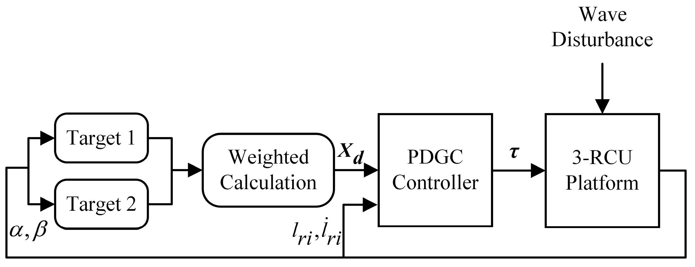
The overall control strategy of the system is shown in Figure 4. First, the two control targets are determined separately according to the bottom disturbance, and then they are weighted to obtain the ideal control target . After that, the control target is input into the control system to adjust the top platform position by the control force to keep the load stable under wave disturbance. At the same time, the drive leg length of the 3-RCU platform and its speed are fed into the control system as feedback signals.
3.2. 3-RCU Platform Analysis
The 3-RCU parallel platform has a simple structure and low cost. We first analyze it in terms of degrees of freedom; using the Grübler–Kutzbach formula [29] we obtain:
where is the DOFs of the platform; is the number of rigid bodies of the platform (including the base); is the number of joints; and is the number of DOFs of joint , i.e., for the rotational joint , for the cylindrical joint , and for the universal joint . And its three independent degrees of freedom are: translation along the z-axis and rotation around the x-axis and y-axis, as well as accompanying DOFs for translation along the x-axis and y-axis. Notably, the platform is constrained from rotating around the z-axis. Figure 5 shows three identical kinematic chains, each consisting of a rotational joint, a cylindrical joint (acting as the driving joint), and a universal joint.
To describe the system, we define at the rotational joints and at the universal joints, is the coordinate system fixed to the base of the hull, with the coordinate origin located at the center of the base, is along the direction of , and is parallel to . is the coordinate system fixed to the top platform, is along the direction of , and is parallel to . Besides that, a joint coordinate system is established at the rotational joints, is perpendicular to the rotation axis, is along the rotation axis, is along the direction of the kinematic chain, is the direction vector of the constraint force, and is the constraint torque. Since the platform has five DOFs, including three independent DOFs and two accompanying DOFs, and cannot rotate along the [30], we established the Euler angles of and obtained the corresponding rotation matrix:
where denotes and denotes , and and of the rotation matrix denote the bottom rotation angles due to disturbance, respectively. The platform has the following constraints:
The inverse kinematics of the platform is solved to obtain the length of each chain with the position of the top platform known, while the forward kinematics is the other case. We set the radius of the circumference of the base as , and the radius of the circumference of the top as , then we can easily obtain the coordinates of and under and , respectively, and then we can obtain the coordinates of under :
where is the vector of pointing to . From Equation (5), we can obtain the constraint relationship between the DOFs of the platform:
therefore, the rotation matrix is simplified to:
Keep the load contact surface level:
When keeping the top platform stable, that is, the target 1, at this time, the control quantity of the system is . Ideally, the closed vector method for inverse kinematics analysis can be utilized when the length of each driving leg is:
Minimize the displacement of the load center of gravity:
When the control target is center of gravity stabilization, which is target 2, the center of gravity of the load remains stationary and the control quantity is , at which time each driving leg length can be expressed as:
where the parameters of the rotation matrix can be expressed, respectively, as:
where h is the height of the center of gravity of the load, H is the initial height of the platform, and denotes the sign function of .
According to the definition of Euler’s angle, we can obtain the angular velocity of the top as:
3.3. PDGC Controller
Gravity compensation means that the gravity force is dynamically distributed to each actuator through real-time and precisely compensates for the gravity force to offset or reduce the influence of the gravitational force applied to the load. This paper is aimed at the wave compensation control of the high center of gravity heavy load; therefore, the load will introduce large disturbances to the control of the three supporting chains during the motion process, which affects the control accuracy of the traditional PD controllers. In addition, gravity compensation can also reduce the dynamic variation range of the controller output force, increase system stability, and thus reduce the steady-state error.
To distribute the gravity of the top platform as well as the load dynamically to each joint space, we need to solve the full Jacobi matrix of the platform. Setting the platform’s six generalized freedoms as , the independent effective degrees of freedom is , and the derivation of Equation (8) can be written as:
where represents the relationship between the driving leg velocity and the generalized velocity of the top platform, it can be expressed as:
is the unit vector of the individual drive leg in the coordinate system . According to the relationship between generalized linear velocity versus generalized angular velocity and effective velocity, we obtain:
where represents the relationship between the generalized linear velocity and the effective velocity, it can be expressed as:
where represents the relationship between the generalized angular velocity and the effective velocity, it can be expressed as:
then, we obtain the relationship between the independent effective velocity and the generalized velocity as:
finally, we obtain the full Jacobian matrix of the system as:
Thus, the gravity of the platform and load on the system can be dynamically distributed to the three supporting chains to obtain the gravity compensation term under the joint space as:
The PDCG control strategy proposed in this paper is shown in Figure 6. Dynamic gravity compensation is added based on the traditional PD controller. After the system is disturbed by the wave, it obtains the desired value of the top platform trajectory by weight calculation, and the ideal leg length of the 3-RCU parallel platform is output by the inverse kinematics. Then, the ideal leg length is compared with the actual one obtained by the feedback to obtain the output force of the PD controller. At the same time, forward kinematics are used to solve the real position of the top. To obtain the real-time position of the top platform, we need to analyze the forward kinematics of the platform, and since the analytical solution of the parallel platform cannot be obtained directly, we can obtain the unique solution by Newton’s method. We set the positional attitude of the top to be , then we obtain the vector as:
by rewriting Equation (8), we can then obtain the set of equations that need to be solved numerically:
Therefore, the output force of the PDGC controller can be expressed as:
where is the leg length error.
4. Simulation Validation
4.1. Description of the Simulation System
To verify the effectiveness of the proposed controller compared to the traditional PD controller, as well as to analyze the control effect under different weighting coefficients We built a simulation control model in MATLAB/Simulink. We first compared the control effects of the PDGG controller and the PD controller under target one using sinusoidal excitation. Then, the angle of the top platform and the displacement of the load center of gravity were analyzed for different values. Finally, random excitations for class 4 sea state were generated by the MSS toolbox [2], and the ideal value was determined by using the trial-and-error method.
In the simulation, we used the Simscape toolbox to build the model of 3-RCU, to achieve the motion of the top platform by applying the control force to the cylindrical joints, and then used the transformed sensor to detect the real-time position of the top. The specific simulation model is shown in Figure 7. In the case of the numerical computation of forward kinematics, too high a numerical solution accuracy can cause an increase in the iteration time, thus affecting the control timing. Due to the small angle value during the platform movement, we chose the initial value of iteration as 0, and then solved the iterative Jacobi matrix in a fixed form to avoid its repeated solution, and at the same time, the number of iterations was limited to less than 10 times, which can completely ensure real-time control.
4.2. Performance under Sinusoidal Excitation
The PD controller is a commonly used feedback controller. Its proportional gain determines the sensitivity of the response, but too large a value introduces overshoot and oscillations. Similarly, the differential gain determines the response to the rate of change of the error, and too large a value will introduce noise [31,32]. When adjusting parameters, start by gradually increasing the proportional gain (). Observe the system response and choose a larger one while avoiding excessive oscillation. Next, adjust the differential gain () to suppress oscillations and reduce overshoot. Select a smaller one to ensure that the system response time is not adversely affected.
In this paper, we tried different gains and determined the parameters while ensuring the response speed, steady-state error, and oscillation avoidance. The specific parameters of the model are shown in Table 1.
In this paper, the sinusoidal excitation consists of a combination of two directions, rotation around the x-axis and rotation around the y-axis, and based on the most frequent portion of the ocean wave excitation, we choose excitations that are, respectively.
In the simulation, the load is a cube with a base side length of 0.2 m and a uniform mass distribution, and its inertia tensor can be expressed as:
where, are the three side lengths of the load, respectively, so the inertia force due to rotation is:
Considering the low-frequency disturbance, with the above excitation, the maximum value of the combined rotationally induced inertial force is about when the control force is applied to keep the platform flat. Its value is much less than the gravitational force of the load and is therefore neglected in the subsequent discussion.
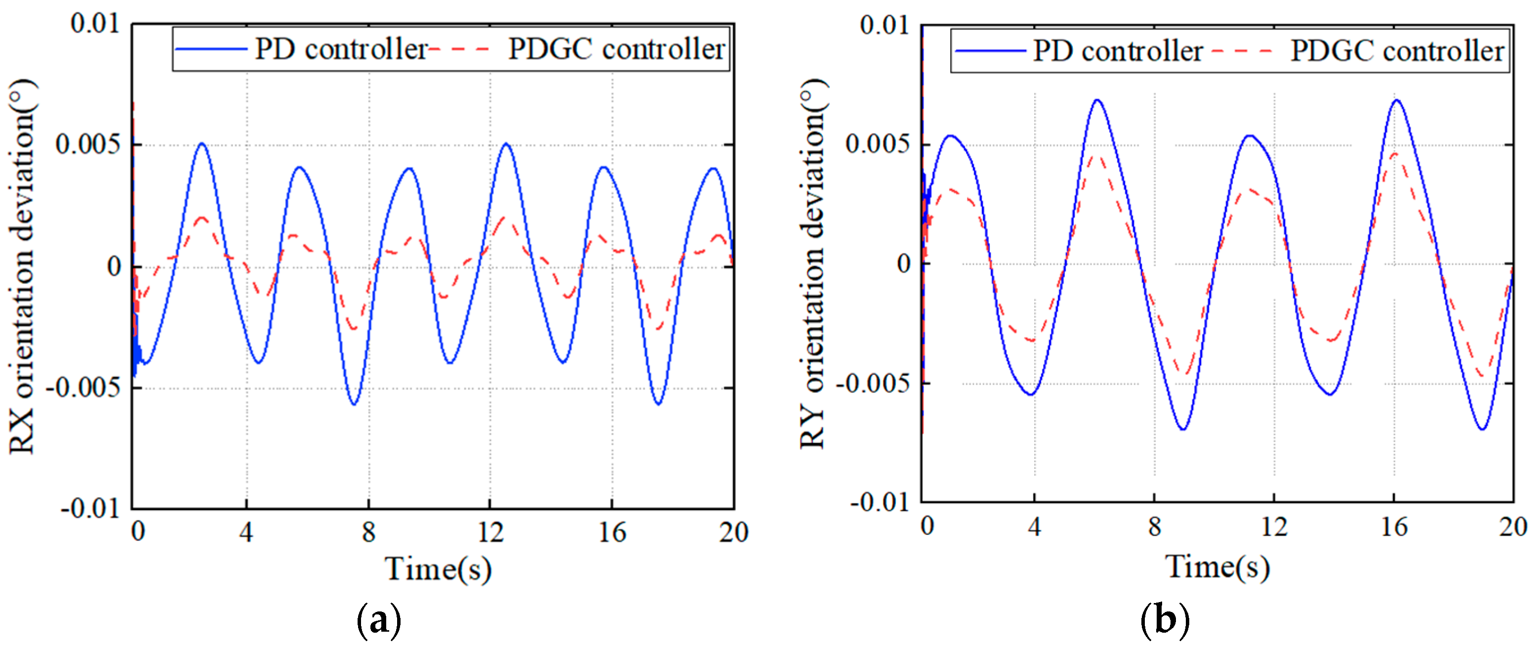
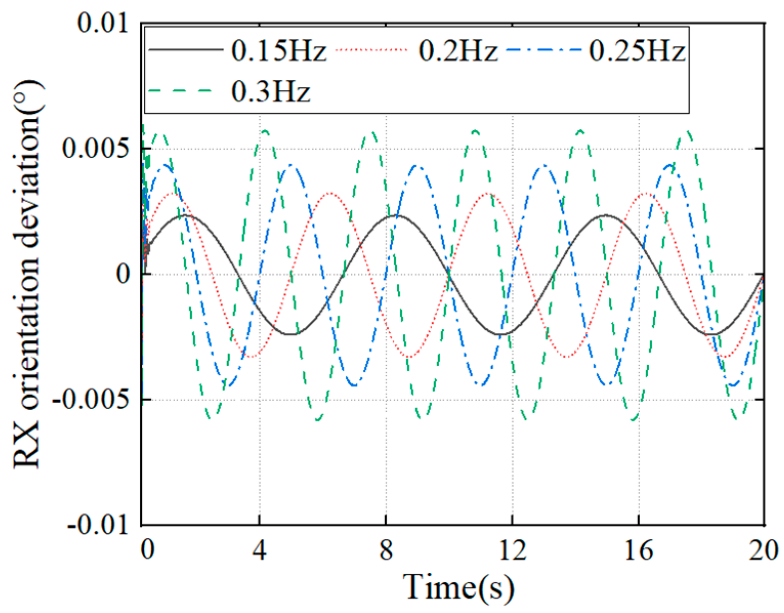
The compensation performance of the PD controller and PDGC controller in both directions is shown in Figure 8. By analyzing both, we can conclude that the proposed controller outperforms the conventional PD controller in terms of compensation, both in the x-direction and in the y-direction. The compensation is more effective in the x-direction, where the RMS (root mean square) value of the residual motion is reduced by 65.23% compared to the PD controller, while in the y-direction, the RMS value is reduced by 37.31%. In low-frequency conditions, the system is more easily controlled because the driving force closely aligns with the dynamic force of gravity, resulting in a smaller output force from the PD controller. This alignment makes the system more manageable. Conversely, the inertial force caused by load motion at higher frequencies leads to greater overshooting and oscillations in the controller’s output compared to lower frequencies. We applied excitations around the x-axis to the system with an amplitude of 3° and frequency from 0.15 Hz to 0.3 Hz. The compensation performance of the gravity compensation controller is shown in Figure 9. Although the results show that the gravity compensation performance is negatively correlated with the frequency, the system has shown great performance at all the given disturbances.
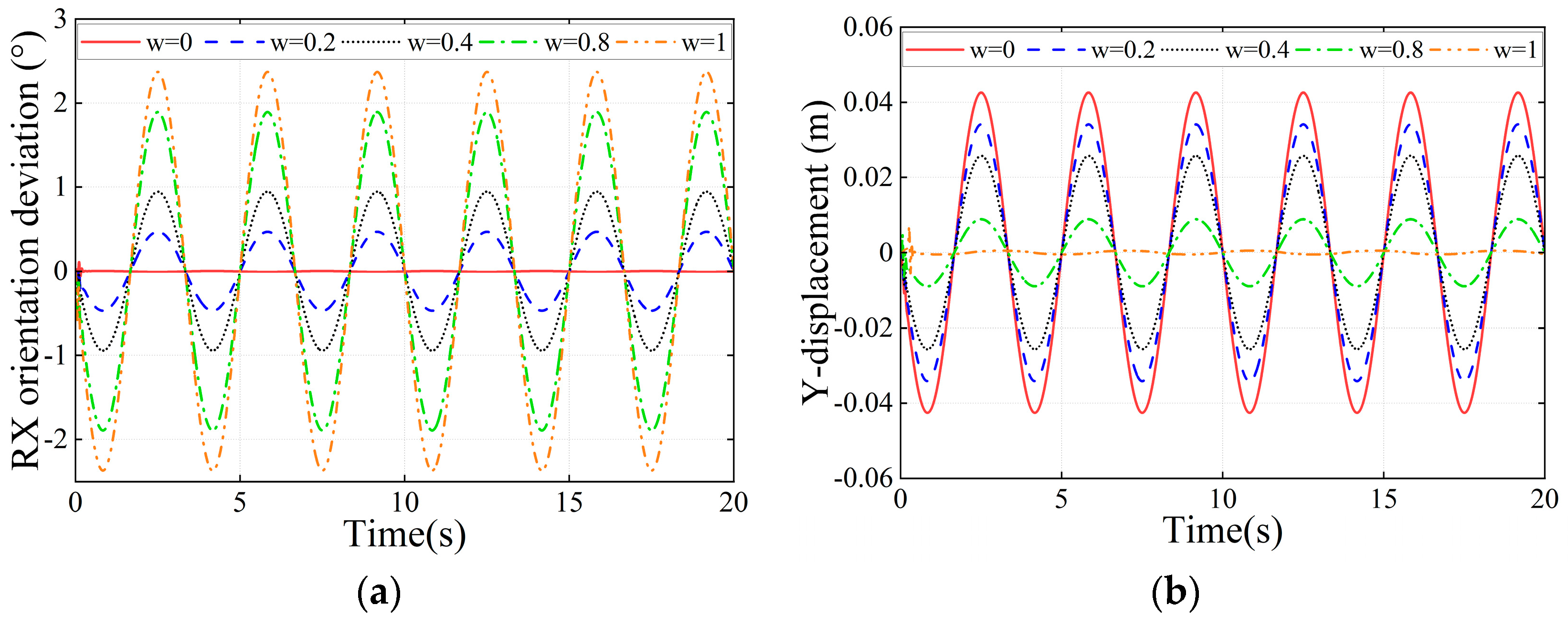
Then, we verified the effectiveness of multi-target control of the system under the excitation in Equation (26) applied separately. As shown in Figure 10, the weighting coefficient w takes values ranging from 0 to 1. When w is closer to 0, the residual angle of the top platform is smaller and the platform is more stable, and when w is closer to 1, the additional displacement of the load’s center of gravity is smaller, and the residual angle of the platform in this case is larger. When w changes from 0 to 0.4, the RMS value of the additional displacement of the center of gravity decreases by 39.54%, while the RMS value of the residual angle of the top platform increases by 0.70 degrees. When w continued to increase to 0.8, the RMS value of the additional displacement of the center of gravity decreased by 73.89% from the beginning, at which time the RMS value of the residual angle of the top platform increased by 1.42°.
4.3. Optimal Weighting Coefficient
During motion compensation, changes in the angle of the top platform or the value of the load acceleration caused by the compensation can increase its overturning moment, thus increasing the instability of the load. Its overturning moment in a certain direction can be expressed as:
where is the load mass and is the load acceleration. The larger the disturbance frequency, the larger the acceleration due to compensation. Different weighting coefficients give different overturning moments. Therefore, we use genetic algorithm optimization to obtain several sets of optimal weight coefficients under the conditions of single direction disturbance and frequency from 0.2 Hz to 0.3 Hz, and the height of the center of mass from 1 m to 2 m, and the optimized objective function is the load overturning moment. The main parameters of the genetic algorithm are shown in Table 2 and the optimization results are shown in Table 3.
With the above optimization results, we used the Curve Fitting Tool in MATLAB to fit the surface of the expression for the optimal weight coefficients, and since the disturbance frequency and the height of the load center of mass are non-correlated quantities, we used a polynomial fit with no cross-terms in the fitting, and the final result is obtained as follows:
5. Experimental Validation
5.1. Description of the Testing System
To verify the performance of the PDGC controller and the effectiveness of the anti-swaying control strategy in real situations, we built a wave compensation test system, which is shown in Figure 12. The excitation is provided by the Stewart platform, and the Stewart platform is controlled by the NI-myRIO controller through the computer. For signal acquisition and measurement, we used an IMU (VN100) placed at the base of the parallel platform to acquire the angle of motion induced by the disturbance. The legs’ length and motion speed of the 3-RCU parallel platform were calculated using the encoders in the motors of the electrical cylinders. A NI-myRIO was applied to implement the proposed controller based on the feedback. In order to observe the control effect, we also placed another IMU on top of the parallel platform, which does not participate in the closed-loop control. In addition, we used a NOKOV Mars2H motion-capture system to measure the motion of the center of gravity by placing the tracking markers on the load. The motion capture system comprises eight cameras, a tracking marker, and a computer. The motion capture system can capture the marker’s displacement, velocity, and acceleration. We first established a world coordinate system at the center of the load’s top while the base platform was stationary, and then we assumed the position of the load’s center of gravity by placing the tracking marker at the center of the top of the load. The reason for this is firstly to facilitate the measurement, and secondly, because the displacement of the measurement point is consistent with the displacement of the center of gravity, so it is the center of the top of the load is not used as the measurement point out of generality. Both the above two signals are processed by the computer.
5.2. Performance of PDGC Controller under Marine Excitation
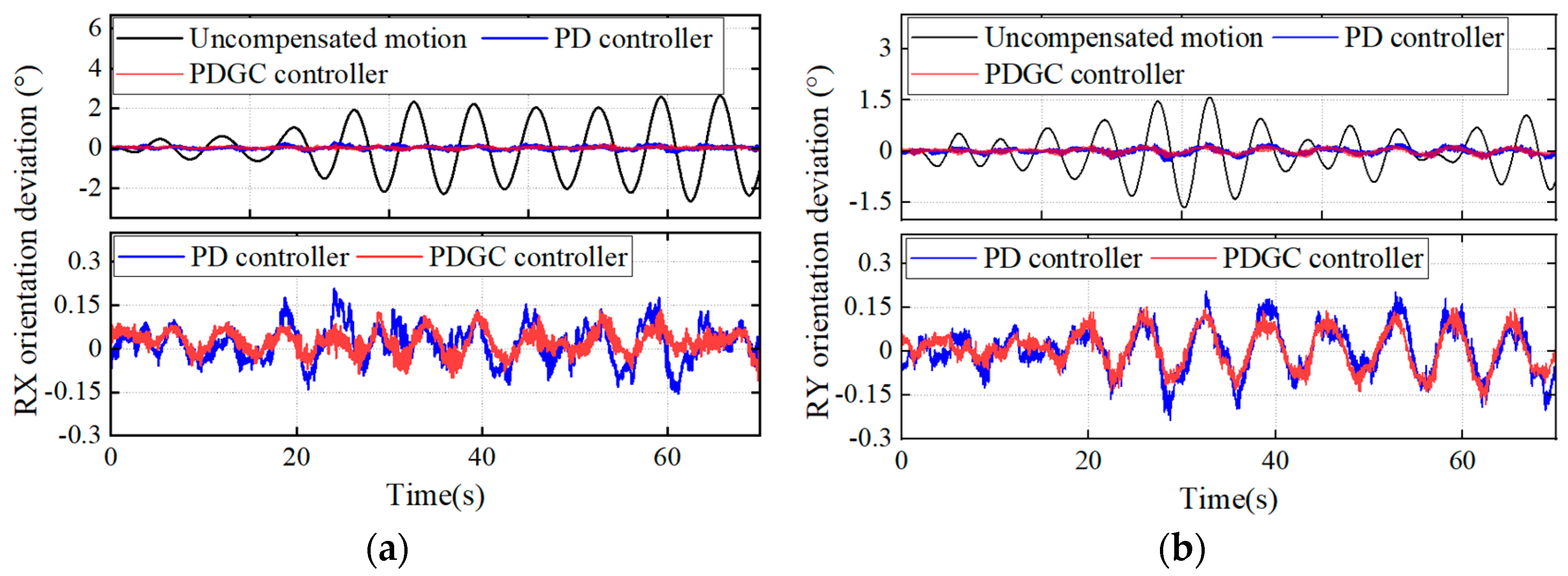
To verify the compensation performance of the system in real marine environments, we used the Stewart platform to generate a random motion under a class 4 sea state, and the control performance of the two controllers is shown in Figure 13. The RMS values of the residual angle around the x-axis are 0.077° and around the y-axis are 0.085° under the traditional PD controller, compared to 0.052° and 0.070° under the PDGC controller control, representing improvements of 32.2% and 17.6%, respectively. Therefore, the PDGC controller outperforms the PD controller under random excitation, which is consistent with the simulation.
5.3. Validation of Anti-Swaying Strategy
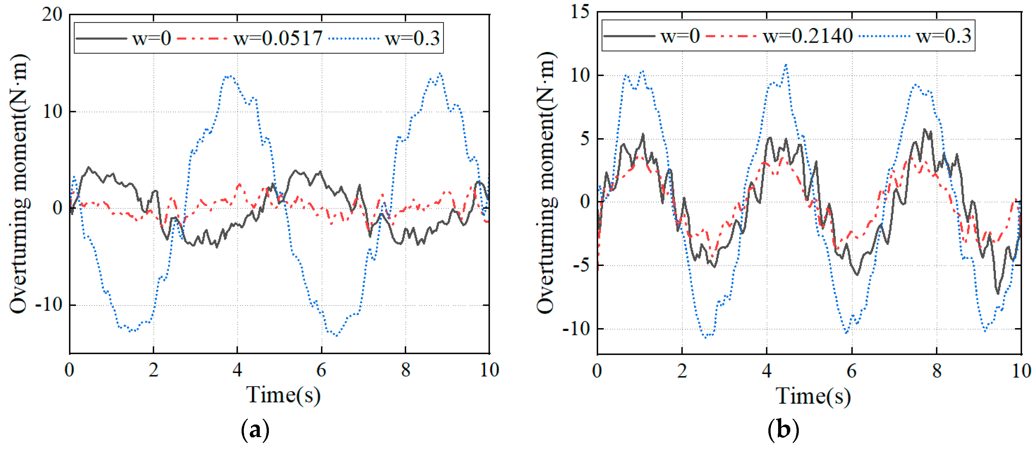
To verify the effectiveness of the anti-swaying strategy, we applied a unidirectional sinusoidal excitation in our experiments to compute the load overturning moment with different weighting factors. The height of the center of mass of the load in the experiment is 0.5 m. The optimal weight coefficients in the control are calculated from Equation (28) and have values of 0.0517 and 0.2140 at frequencies of 0.2 Hz and 0.3 Hz, respectively. The overturning moment calculated from the load acceleration and the top platform angle is shown in Figure 14. At a disturbance frequency of 0.2 Hz, the RMS value of the overturning moment of the load at the optimum weight is about 1.67 N·m, which is a decrease of about 44.33% and 82.02% compared to 3.00 N·m and 9.29 N·m in the other two cases, respectively. At a disturbance frequency of 0.3 Hz, the RMS value of overturning moment of the load under optimum weights is reduced by about 50.23% and 71.73% compared to the other two cases.
6. Conclusions
Given that high center-of-mass loads can overturn during ocean transportation, this paper proposes a control strategy to improve the stability of such loads based on a gravity-compensated PD controller. Multi-target control is used to achieve a trade-off between the rotation angle of the 3-RCU platform and the plane displacement of the load’s center of gravity, and an evaluation parameter T (which is the overturning moment of the load) is proposed to measure the stability of the load. This paper verified the effectiveness of the proposed controller by simulation under sinusoidal excitation and the feasibility of control using weighting coefficients. The optimal weight coefficients of the loads were then solved by a genetic algorithm at different frequencies. Finally, a testing system was built, and the control performance of the proposed controller was improved by 32.2% under random excitation in class 4 sea state. The load stability under the optimal was also verified under experimental conditions, which is significant in guiding practical applications in the future.
Author Contributions
Conceptualization, Z.L., P.L., D.N. and S.W.; data curation, Z.L.; formal analysis, Z.L.; funding acquisition, and S.W.; investigation, Z.L.; methodology, Z.L.; project administration, P.L. and D.N.; software, Z.L.; supervision, P.L. and D.N.; validation, Z.L.; visualization, Z.L.; writing—original draft, Z.L.; writing—review and editing, P.L. and D.N. All authors have read and agreed to the published version of the manuscript.
Funding
This research was funded by the National Natural Science Foundation of China (grant no. 52088102), the Nature Science Foundation of Shandong (grant no. 2022HWYQ-067), and the Taishan Scholars Program of Shandong Province (no. tsqn202211062).
Data Availability Statement
Available on request.
Conflicts of Interest
The authors declare no conflicts of interest.
References
- Sanden, S.; Hovland, G. Inverse kinematic control of an industrial robot used in Vessel-to-Vessel Motion Compensation. In Proceedings of the 2017 25th Mediterranean Conference on Control and Automation (MED), Valletta, Malta, 3–6 July 2017; IEEE: Piscataway, NJ, USA; pp. 1392–1397. [Google Scholar]
- Fossen, T.I. Handbook of Marine Craft Hydrodynamics and Motion Control; John Wiley & Sons: Hoboken, NJ, USA, 2011. [Google Scholar]
- Halvorsen, H.S.; Øveraas, H.; Landstad, O.; Smines, V.; Fossen, T.I.; Johansen, T.A. Wave motion compensation in dynamic positioning of small autonomous vessels. J. Mar. Sci. Technol. 2021, 26, 693–712. [Google Scholar] [CrossRef]
- Elbadawy, A.A.; Shehata, M.M. Anti-sway control of marine cranes under the disturbance of a parallel manipulator. Nonlinear Dyn. 2015, 82, 415–434. [Google Scholar] [CrossRef]
- Schlick, E.O.; Wurl, M. Apparatus for Minimizing the Oscillatory Movements of Ships and Other Oscillating Bodies. U.S. Patent No. 944,511, 28 December 1909. [Google Scholar]
- Said, L.; Sheng, L.; Farouk, N.; Latifa, B. Modeling, design and control of a ship carried 3 DOF stabilized platform. Res. J. Appl. Sci. Eng. Technol. 2012, 4, 3843–3851. [Google Scholar]
- Tao, S.; Fei, C.; Xiuzhi, L.; He, L.; Yi, W. Research of the feedforward control system of 3-axis stable platform based on disturbance observer. Syst. Sci. Control Eng. 2018, 6, 324–332. [Google Scholar] [CrossRef]
- Zhang, M.; Guan, Y.; Zhao, W. Adaptive super-twisting sliding mode control for stabilization platform of laser seeker based on extended state observer. Optik 2019, 199, 163337. [Google Scholar] [CrossRef]
- Stewart, D. A platform with six degrees of freedom. Proc. Inst. Mech. Eng. 1965, 180, 371–386. [Google Scholar] [CrossRef]
- Liu, S.; Peng, G.; Gao, H. Dynamic modeling and terminal sliding mode control of a 3-DOF redundantly actuated parallel platform. Mechatronics 2019, 60, 26–33. [Google Scholar] [CrossRef]
- Xu, P.; Cheung, C.F.; Li, B.; Ho, L.T.; Zhang, J.F. Kinematics analysis of a hybrid manipulator for computer controlled ultra-precision freeform polishing. Robot. Comput. Integr. Manuf. 2017, 44, 44–56. [Google Scholar] [CrossRef]
- Jaouen, F.; van den Berg, J.; van der Schaaf, H.; May, E.; Koppenol, J. How does barge-master compensate for the barge motions: Experimental and numerical study. In Proceedings of the ASME 2012 31st International Conference on Offshore Mechanics and Arctic Engineering, Rio de Janeiro, Brazil, 1–6 July 2012; American Society of Mechanical Engineers: New York, NY, USA; Volume 44885, pp. 35–46. [Google Scholar]
- De Zeeuw, W.A. Ship Motion Compensation Platform for High Payloads: Dynamic Analysis and Control. Master’s Thesis, Delft University of Technology, Delft, The Netherlands, August 2012. [Google Scholar]
- Hu, X.; Li, F.; Tang, G. Kinematics analysis of 3UPU_UP coupling parallel platform in the marine environment. IEEE Access 2020, 8, 158142–158151. [Google Scholar] [CrossRef]
- Tang, G.; Lu, P.; Hu, X.; Men, S. Control system research in wave compensation based on particle swarm optimization. Sci. Rep. 2021, 11, 15316. [Google Scholar] [CrossRef] [PubMed]
- Lan-yong, Z.; An, C.; Yi-xuan, D.; Bing, L. Multivariable fuzzy genetic controller for stabilized platform. In Proceedings of the 2015 34th Chinese Control Conference (CCC), Hangzhou, China, 28–30 July 2015; IEEE: Piscataway, NJ, USA; pp. 783–788. [Google Scholar]
- Lv, W.; Tao, L.; Ji, Z. Design and control of cable-drive parallel robot with 6-dof active wave compensation. In Proceedings of the 2017 3rd International Conference on Control, Automation and Robotics (ICCAR), Nagoya, Japan, 22–24 April 2017; IEEE: Piscataway, NJ, USA; pp. 129–133. [Google Scholar]
- Campos, A.; Quintero, J.; Saltaren, R.; Ferre, M.; Aracil, R. An active helideck testbed for floating structures based on a stewart-gough platform. In Proceedings of the 2008 IEEE/RSJ International Conference on Intelligent Robots and Systems, Nice, France, 22–26 September 2008; IEEE: Piscataway, NJ, USA; pp. 3705–3710. [Google Scholar]
- Cai, Y.; Zheng, S.; Liu, W.; Qu, Z.; Zhu, J.; Han, J. Sliding-mode control of ship-mounted Stewart platforms for wave compensation using velocity feedforward. Ocean Eng. 2021, 236, 109477. [Google Scholar] [CrossRef]
- He, Y.; Wu, Y.; Li, W. Sliding mode control for offshore parallel antenna platform with large orientation workspace. ISA Trans. 2022, 128, 90–108. [Google Scholar] [CrossRef]
- Ono, T.; Eto, R.; Yamakawa, J.; Murakami, H. Control Simulations for a Stewart Platform Compensator Mounted on Moving Base. In Proceedings of the ASME International Mechanical Engineering Congress and Exposition, Salt Lake City, UT, USA, 8–14 November 2019; American Society of Mechanical Engineers: New York, NY, USA; Volume 59414, p. V004T05A017. [Google Scholar]
- Liu, J.; Chen, X. Adaptive control based on neural network and beetle antennae search algorithm for an active heave compensation system. Int. J. Control Autom. Syst. 2022, 20, 515–525. [Google Scholar] [CrossRef]
- Chen, W.; Wang, S.; Li, J.; Lin, C.; Yang, Y.; Ren, A.; Wei, L.; Zhao, X.; Zhang, W.; Guo, W.; et al. An ADRC-based triple-loop control strategy of ship-mounted Stewart platform for six-DOF wave compensation. Mech. Mach. Theory 2023, 184, 105289. [Google Scholar] [CrossRef]
- Yu, D.; Chen, W.X. Analysis of erection and transportation of offshore wind power single-pile foundation stabilized pile platform. China Harb. Constr. 2022, 42, 10–14. (In Chinese) [Google Scholar]
- Bingul, Z.; Karahan, O. Dynamic Modeling and Simulation of Stewart Platform; INTECH Open Access Publisher: London, UK, 2012. [Google Scholar]
- Tang, G.; Lei, J.; Li, F.; Zhu, W.; Xu, X.; Yao, B.; Claramunt, C.; Hu, X. A modified 6-DOF hybrid serial–parallel platform for ship wave compensation. Ocean. Eng. 2023, 280, 114336. [Google Scholar] [CrossRef]
- Kizir, S.; Bingul, Z. Position control and trajectory tracking of the Stewart platform. In Serial and Parallel Robot Manipulators-Kinematics, Dynamics, Control and Optimization; InTech: Istanbul, Turkey, 2012; Volume 3, pp. 179–202. [Google Scholar]
- Ren, Z.; Skjetne, R.; Verma, A.S.; Jiang, Z.; Gao, Z.; Halse, K.H. Active heave compensation of floating wind turbine installation using a catamaran construction vessel. Mar. Struct. 2021, 75, 102868. [Google Scholar] [CrossRef]
- Tsai, L.W. The mechanics of serial and parallel manipulators. In Robot Analysis; John Wiley & Sons, Inc.: Hoboken, NJ, USA, 1999. [Google Scholar]
- Wang, Y.; Yu, J.; Pei, X. Fast forward kinematics algorithm for real-time and high-precision control of the 3-RPS parallel mechanism. Front. Mech. Eng. 2018, 13, 368–375. [Google Scholar] [CrossRef]
- Su, Y.X.; Duan, B.Y.; Zheng, C.H. Nonlinear PID control of a six-DOF parallel manipulator. IEE Proc. Control Theory Appl. 2004, 151, 95–102. [Google Scholar] [CrossRef]
- Nguyen, C.C.; Antrazi, S.S.; Zhou, Z.L.; Campbell, C.E., Jr. Adaptive control of a Stewart platform-based manipulator. J. Robot. Syst. 1993, 10, 657–687. [Google Scholar] [CrossRef]
Figure 1.
Six-dimensional disturbance of the ocean.

Figure 2.
Control effect for target 1. (a) Uncontrolled; (b) controlled.

Figure 3.
Control effect for target 2.
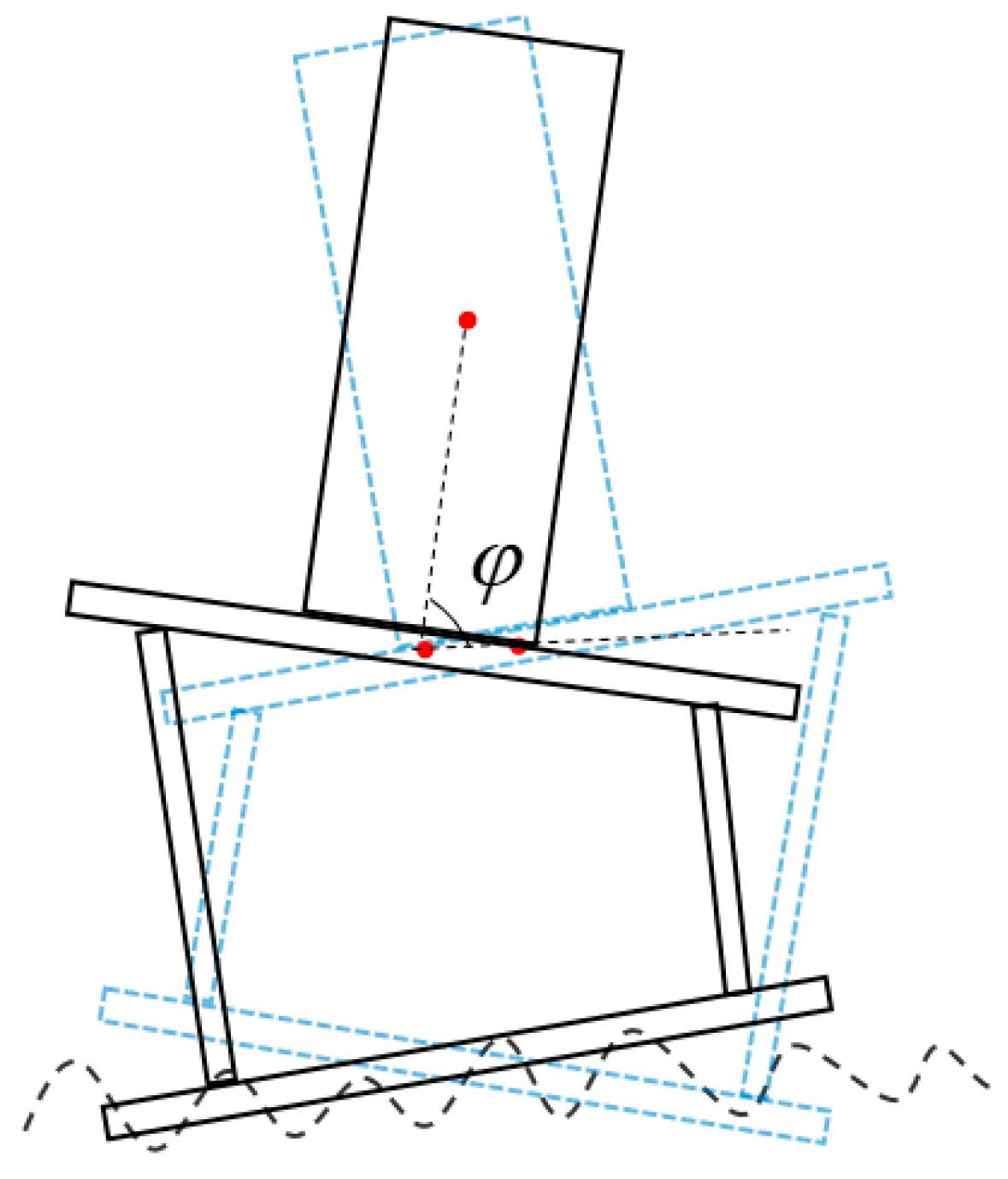
Figure 4.
Block diagram of system control strategy.

Figure 5.
Kinematic relation of the 3-RCU platform.
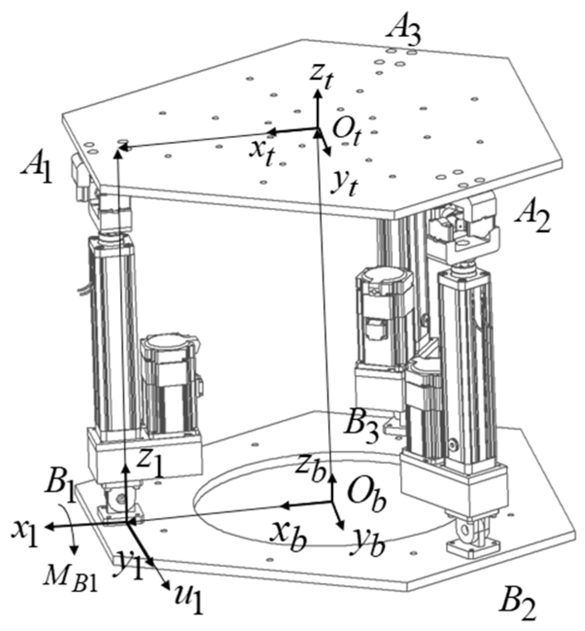
Figure 6.
Block diagram of the PDGC controller scheme.

Figure 7.
Simulation model in Simulink.
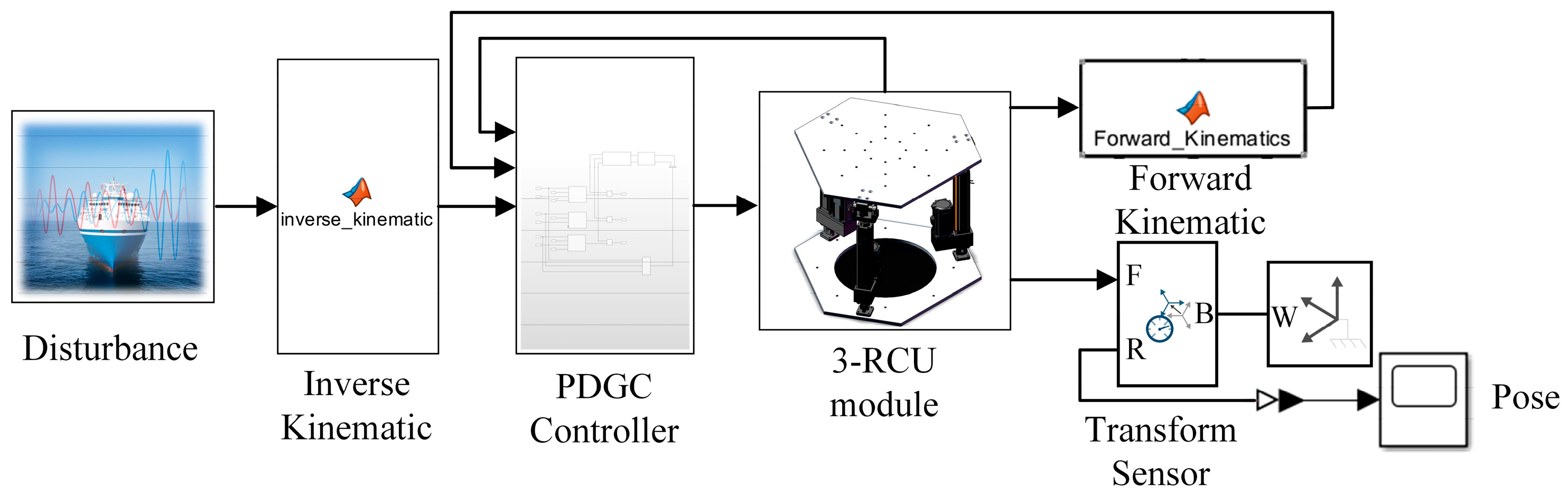
Figure 8.
Residual motion on the top platform with PD and PDGC controllers. (a) RX direction; (b) RY direction.
Figure 8.
Residual motion on the top platform with PD and PDGC controllers. (a) RX direction; (b) RY direction.

Figure 9.
Residual motion at different frequencies under PDGC controller.

Figure 10.
Residual angle of the top around x and additional displacement of the center of gravity along the y for different w conditions. (a) RX angle; (b) Y displacement.
Figure 10.
Residual angle of the top around x and additional displacement of the center of gravity along the y for different w conditions. (a) RX angle; (b) Y displacement.

Figure 11.
Fitting surfaces with weight coefficient.
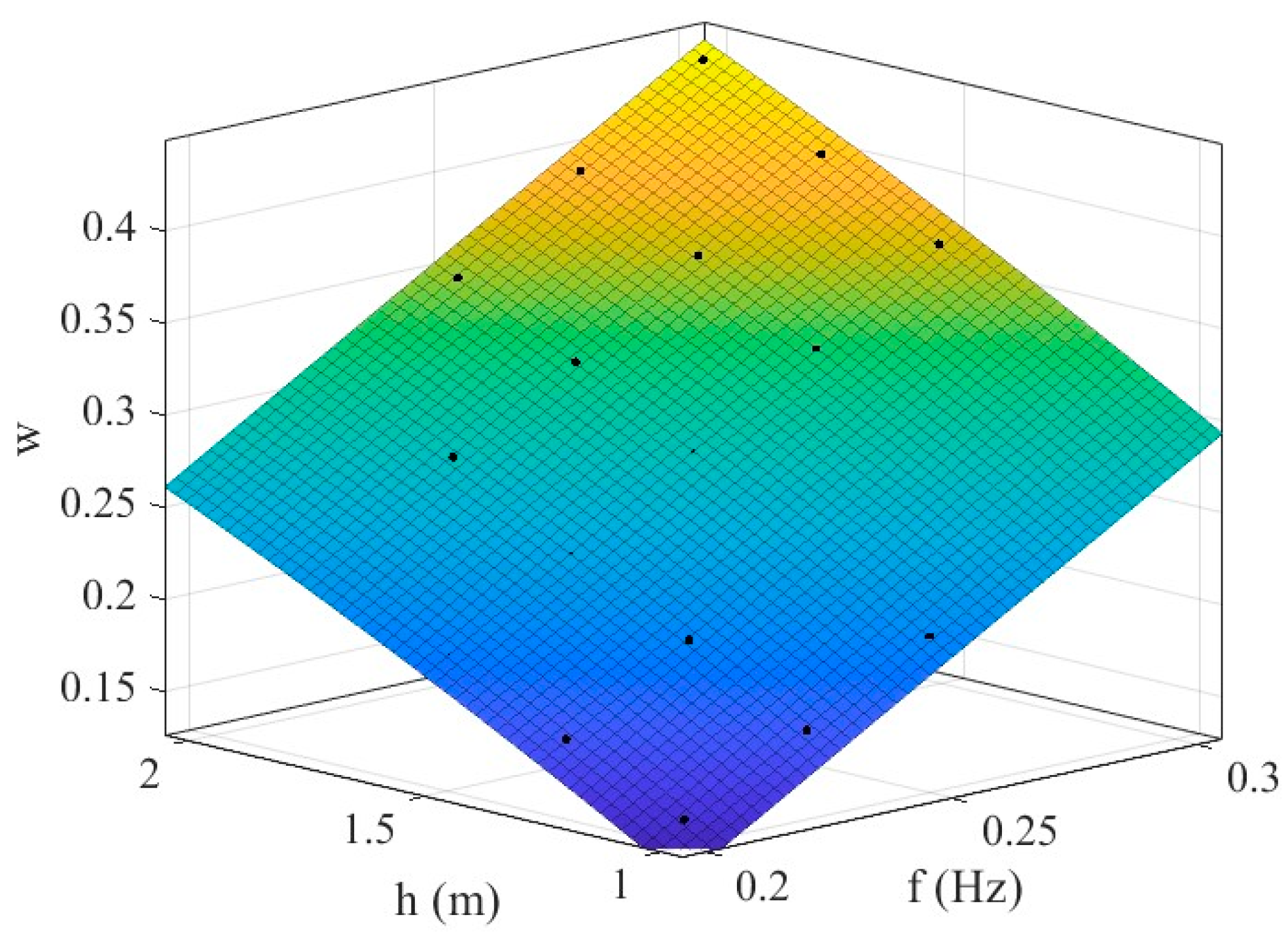
Figure 12.
Wave compensation testing system. The blue arrow indicates the measuring sensor, the red arrow indicates the measurement signal, and the black arrow indicates the control signal.
Figure 12.
Wave compensation testing system. The blue arrow indicates the measuring sensor, the red arrow indicates the measurement signal, and the black arrow indicates the control signal.

Figure 13.
Performance of under class 4 sea state excitation. (a) RX direction; (b) RY direction.

Figure 14.
Load overturning moment. (a) Disturbance frequency 0.2 Hz; (b) disturbance frequency 0.3 Hz.
Figure 14.
Load overturning moment. (a) Disturbance frequency 0.2 Hz; (b) disturbance frequency 0.3 Hz.

Table 1.
Parameters of the simulation system.
| Parameters | Value |
|---|---|
| Circumradius of base r | 0.345 m |
| Height of load center of gravity h | 1 m |
| Total mass of moving platform and load M | 100 kg |
| Initial height of 3-RCU H | 0.78 m |
| [3 × 10⁵ 3 × 10⁵ 3 × 10⁵] | |
| [2 × 10³ 2 × 10³ 2 × 10³] |
Table 2.
Main parameters of the genetic algorithm.
| Parameters | Value |
|---|---|
| Population size | 100 |
| Maximum number of function evaluations | 10,000 |
| Probability of crossover | 1 |
| Distribution index of polynomial mutation | 20 |
Table 3.
Genetic algorithm optimized weights w.
| (m) | 1 | 1.25 | 1.5 | 1.75 | 2 | |
|---|---|---|---|---|---|---|
| (Hz) | ||||||
| 0.3 | 0.2821 | 0.3232 | 0.3650 | 0.3986 | 0.4348 | |
| 0.275 | 0.2476 | 0.2845 | 0.3222 | 0.3583 | 0.3889 | |
| 0.25 | 0.2114 | 0.2450 | 0.2801 | 0.3150 | 0.3453 | |
| 0.225 | 0.1752 | 0.2091 | 0.2391 | 0.2781 | 0.2978 | |
| 0.2 | 0.1412 | 0.1698 | 0.1985 | 0.2280 | 0.2530 | |
Table 4.
Goodness of fit.
| Evaluation Parameters | Results |
|---|---|
| R-squared | 0.99524 |
| Sum of Squared Errors (SSE) | 0.0006611 |
| Adjusted R-squared | 0.99429 |
| Root Mean Square Error (RMSE) | 0.005749 |
Disclaimer/Publisher’s Note: The statements, opinions and data contained in all publications are solely those of the individual author(s) and contributor(s) and not of MDPI and/or the editor(s). MDPI and/or the editor(s) disclaim responsibility for any injury to people or property resulting from any ideas, methods, instructions or products referred to in the content. |
© 2024 by the authors. Licensee MDPI, Basel, Switzerland. This article is an open access article distributed under the terms and conditions of the Creative Commons Attribution (CC BY) license (https://creativecommons.org/licenses/by/4.0/).
Share and Cite
MDPI and ACS Style
Lv, Z.; Liu, P.; Ning, D.; Wang, S. Anti-Swaying Control Strategy of Ship-Mounted 3-RCU Parallel Platform Based on Dynamic Gravity Compensation. Machines 2024, 12, 209. https://doi.org/10.3390/machines12030209
AMA Style
Lv Z, Liu P, Ning D, Wang S. Anti-Swaying Control Strategy of Ship-Mounted 3-RCU Parallel Platform Based on Dynamic Gravity Compensation. Machines. 2024; 12(3):209. https://doi.org/10.3390/machines12030209
Chicago/Turabian StyleLv, Zhiyuan, Pengfei Liu, Donghong Ning, and Shuqing Wang. 2024. "Anti-Swaying Control Strategy of Ship-Mounted 3-RCU Parallel Platform Based on Dynamic Gravity Compensation" Machines 12, no. 3: 209. https://doi.org/10.3390/machines12030209
Note that from the first issue of 2016, this journal uses article numbers instead of page numbers. See further details here.