1. Introduction
During the cutting process, it is very important to know, as precisely as possible, the relationship between the vibration behavior of the machine tool-cutting tool-workpiece system and the cutting conditions (cutting speed, feed rate and axial depth of cut) in order to achieve high workpiece surface quality [
1,
2].
This is especially the case when it comes to the use of contemporary computer numerical control (CNC) machine tools in micromachining processes [
3], for which it is crucial to define a group of optimal cutting conditions aiming at:
ensuring dynamic stability [
4,
5] of the cutting process without side vibration phenomena [
6] with an unfavorable impact both on the workpiece surface quality and the cutting tool life;
achieving efficient machine tool performance;
avoiding rapid development of cutting tool wear;
reducing processing time and consequently production costs.
Finding an appropriate combination of process parameters has been such a challenging problem that a great deal of research has been devoted to the topic. Generally, it is difficult to define optimal cutting conditions to fit every cutting process. However, it is feasible to find out proper cutting parameters for a specific combination of machine tool, cutting tool and workpiece material.
The aim of the paper is to investigate experimentally the effect of the tool runout both on the cutting forces and the resulting workpiece surface. The paper follows a previous one [
7], which was dealing with the effect of vibration phenomena on the workpiece topomorphy in general. The current research puts particular emphasis on the effect of vibrations caused by cutter runout on the workpiece surface quality. This is even more important when it comes to micromachining [
3,
8,
9].
Tool clamping is usually accompanied by cutter runout. Although the cutter runout may be reduced by careful clamping performed by skilled machinists, a residual runout exists in the micro scale.
In the case of a residual cutter runout, unequal cutting forces are developed on the tool flutes during each cutter revolution. One of the flutes, where the eccentricity appears, undertakes the main cutting work and, therefore, is over-loaded, whereas the other flutes remain under-loaded. Because of that higher stresses are developed on the rake surface and the principal cutting edge of the particular flute. Such a situation leads to early flute wear, which deteriorates the whole cutting process. Moreover, the process is susceptible to becoming unstable [
1].
Additionally, the effect of the cutter runout should be taken into consideration in order to secure the surface quality in profile end milling [
10]. In this case, the enhanced cutting forces induce tool bending, thereby worsening the surface finish.
To investigate the effect of cutter runout on the cutting forces and the workpiece surface texture, dedicated experiments were conducted evaluating the cutting forces and the workpiece surface topomorphy. In particular, by means of experimental results, the cutting conditions which affect the cutting process outcome were studied. In this sense, the purpose of this experimental study was to find out the effect of the cutter runout on the cutting mechanism, on the tool vibration, and sequentially on the workpiece surface quality.
2. Experimental Procedure
To measure the cutting forces, specific milling experiments were conducted on the 5-axis CNC machining center DECKEL MAHO MH600C (DECKEL MAHO GmbH, Pfronten, Germany) shown in
Figure 1. Before the measurement of the cutting forces, the workpiece was roughened in order to achieve the necessary flatness thus ensuring a constant depth of cut through the entire machined surface. For the roughing process, under the usage of coolant, an end-mill cutting tool of 40 mm diameter was selected.
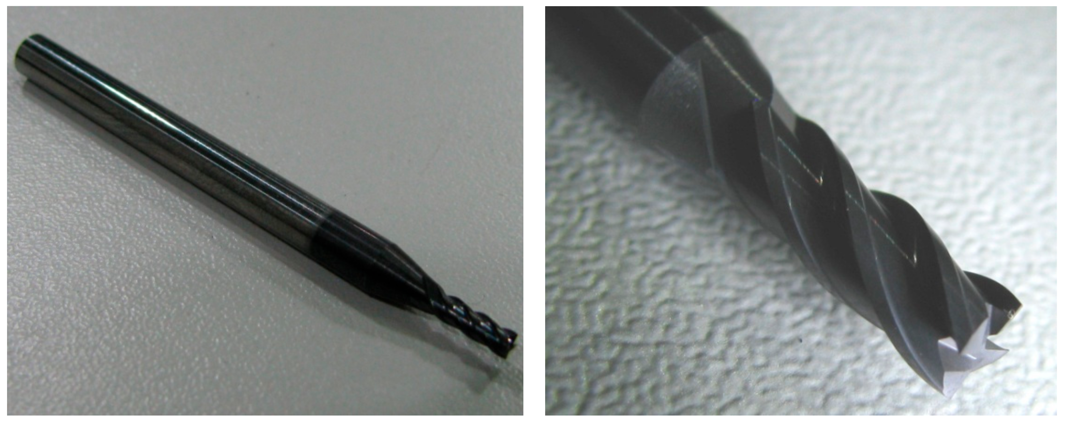
The cutting tool used in the experiments was manufactured by the OSAWA Company (Osaka, Japan) with type G2CS4, and is shown in
Figure 2. It is a 4-flute end-mill cutter of 2 mm diameter. The cutting tool material is micrograin carbide with multilayer physical vapor deposition (PVD) high performance coating of 3500 HV hardness. Due to its excellent abrasion resistance and the fact that it can withstand higher temperatures, this cutting tool is suitable for working with or without lubrication at high cutting speeds. All experiments of the research were performed under dry machining conditions.
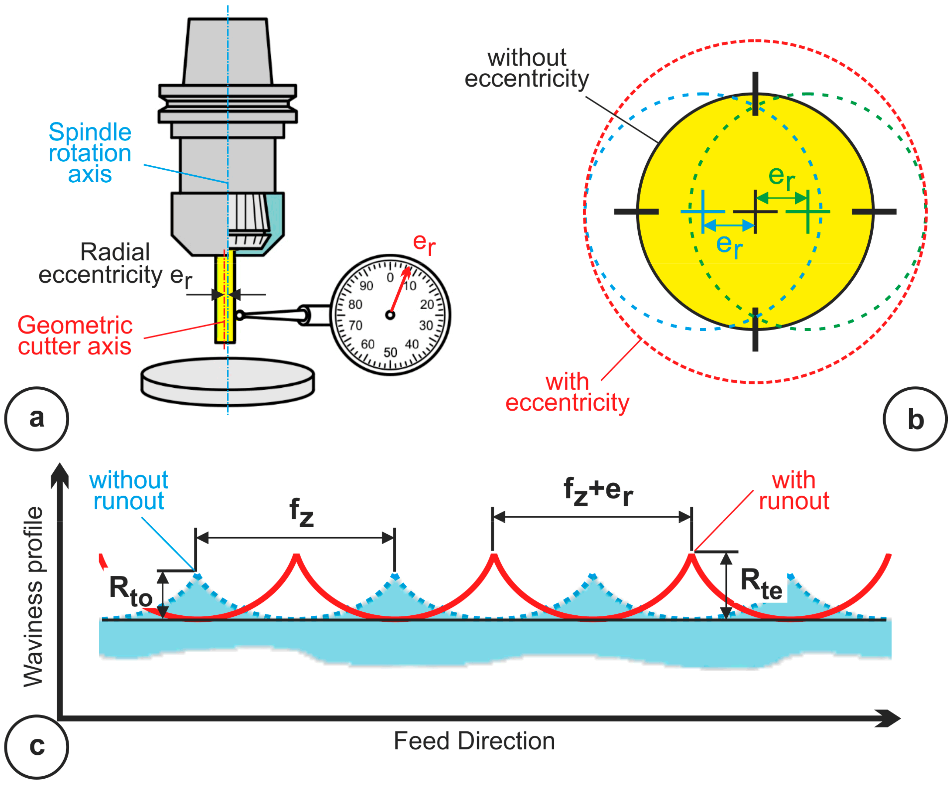
The cutting tool was mounted on the ISO40 Tool holder by the aim of a ER32 collet. By a typical tool clamping procedure, the cutter was set up with a radial eccentricity leading to cutter runout of 7 μm. The resulted cutter runout was measured using a specific tool measurement device (DMG Violinear) with 1 μm resolution. The result of the eccentric tool mounting is schematically explained in
Figure 3a.
The cutting kinematics considering the cutter runout is depicted on the surface texture with a varied waviness profile (
Figure 3c). Specifically, the height of the waviness profile is increased as well as the waviness length. The theoretical maximum roughness R
t of the roughness profile is expressed by Equation (1) when the tool is ideally axisymmetric and, correspondingly, by Equation (2) in the case that a tool eccentricity exists [
11,
12]. From these equations it can be clearly seen that an increase in feed per tooth f
z causes surface roughness growth, whereas an increase in tool diameter D, causes a decline in surface roughness.
It is also worth noticing that the surface roughness parameters in the above equations often vary from the real surface roughness values, especially for low tool feed speed. One of the reasons of these discrepancies are cutter displacements related to the cutter’s runout. Moreover, the tool’s vibrations have an additional effect also.
The parameter e
r depicted in
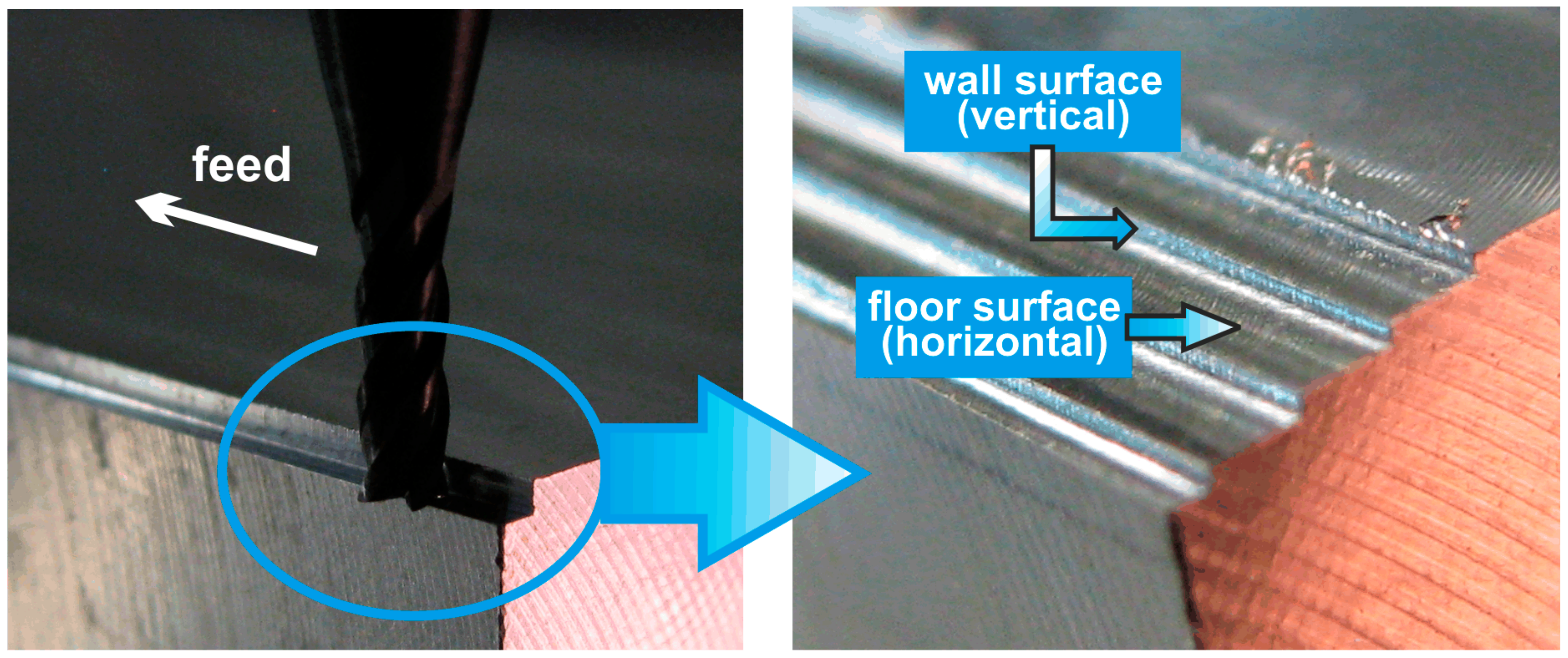
Figure 3b denotes the radial displacement between the cutting edges related to cutter runout. The cutter’s static runout is mainly due to the offset between the position of the tool rotation axis and the spindle rotation axis. It is worth mentioning that in an end-milling process this radial cutter runout affects only the wall surface of the machined workpiece.
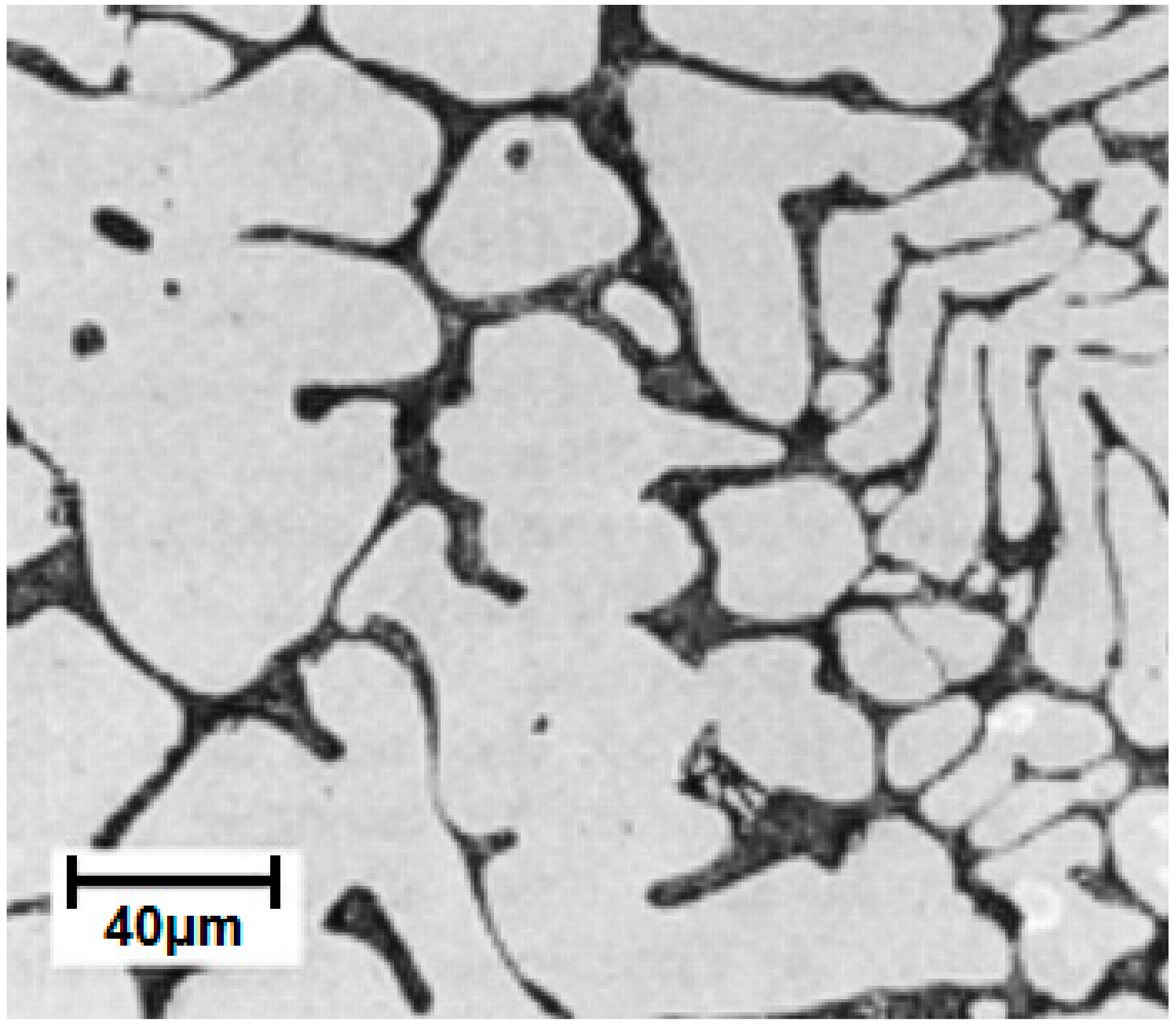
The material of the workpieces used for the experiments was aluminum alloy of class 7075 T651 (AlZn5.5MgCu). In
Figure 4 the metallographic microstructure is shown. In the micrograph there are visible various phases granulation formed (Al-MgZn2, MgSi2, and phase contains Fe) in the Al matrix. This material has very high strength and, therefore, is used widely in applications in aerospace and in military industry.
In order to measure the cutting forces, metrological equipment was used, which consists of the stationary dynamometer type KISTLER 9257B (Kistler Group, Winterthur, Switzerland), the charge amplifier type KISTLER 5233A and an Analog/Digital converter of the National Instruments type NI PCI-MIO-16E (National Instruments, Austin, TX, USA) which was connected to a computer.
The three cutting force components Fx, Fy and Fz were measured in real time, whereby Fx component represents the feed force, Fy component represents the back force and Fz component represents the main cutting force (
Figure 1). The measurements were taken with the aid of the inbuilt piezoelectric sensors. The output of the sensors is an electric charge (Q) linearly proportional to the force acting to the sensor. The charge amplifier intensifies this charge into a normalized voltage signal, which can then be digitized and acquired in the signal-processing system. The digital signals are subjected to a further processing in order to be evaluated both in time and frequency domain. The cutting parameters of the conducted experiments are shown in
Table 1.
3. Experimental Results and Discussion
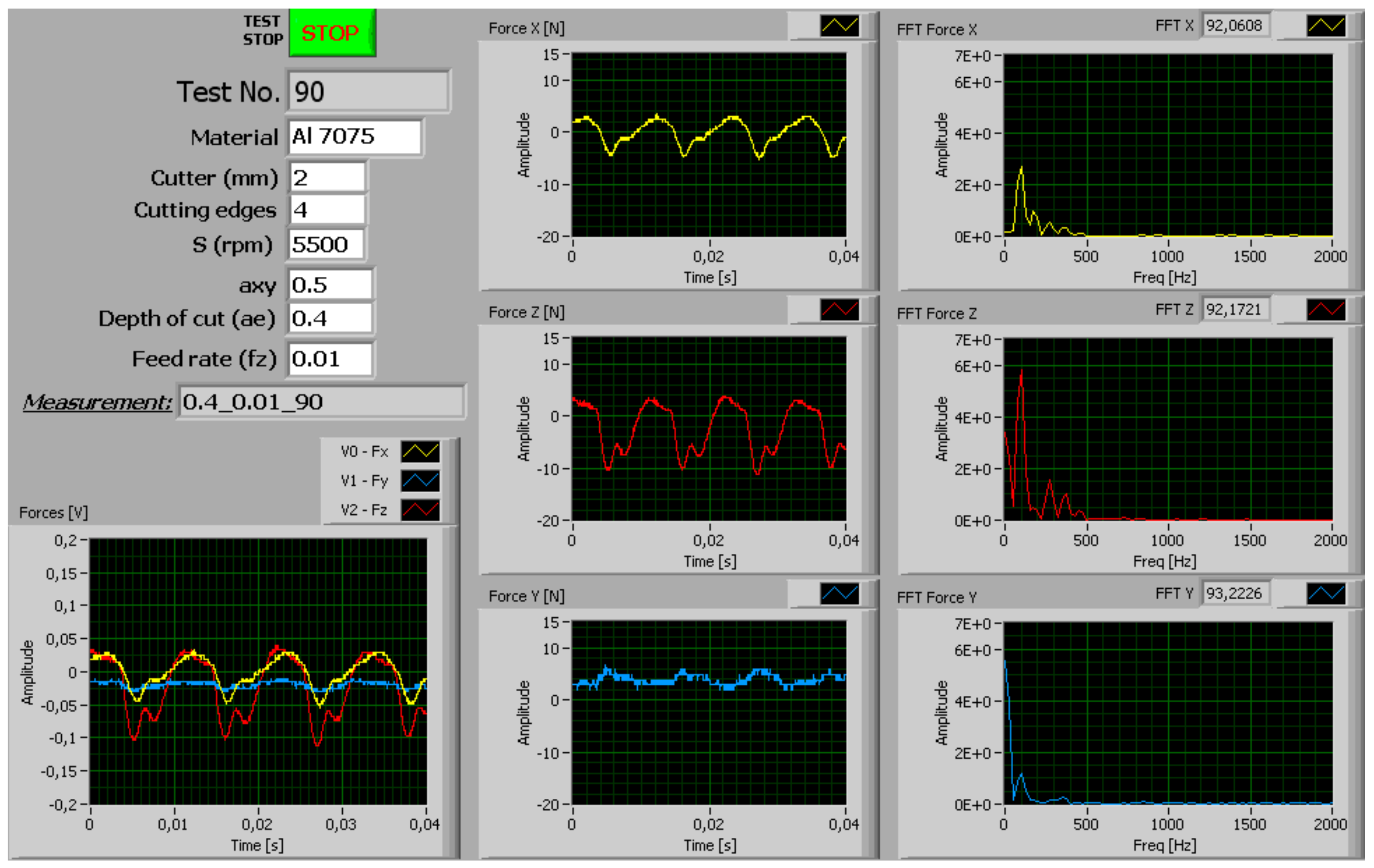
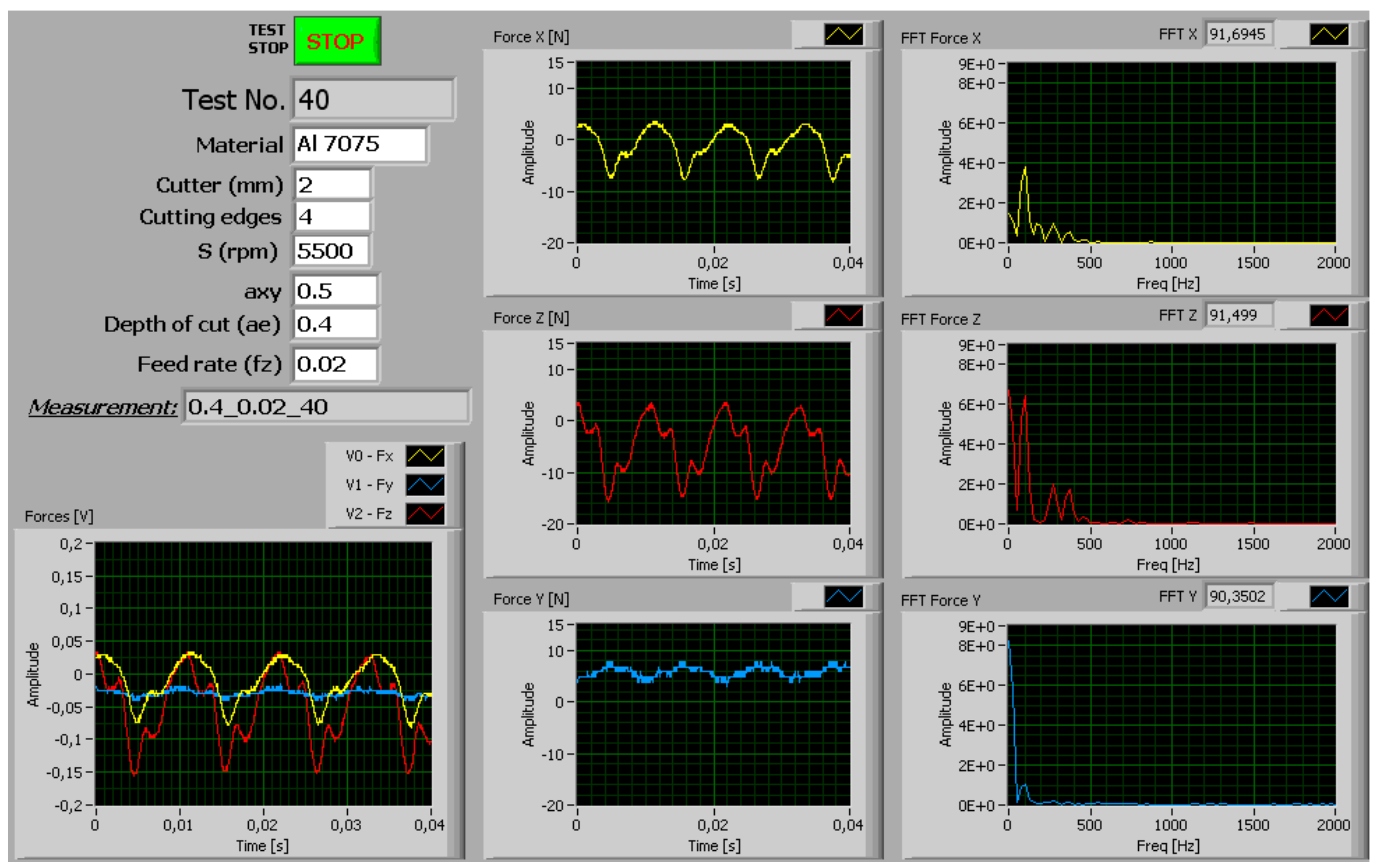
The cutting force components, after undergoing a low-pass filtering of 200 Hz, were recorded within a time frame of 0.04 s by a sampling rate of 25,000 samples/s. In
Figure 5 and
Figure 6, typical measurement graphical interfaces are illustrated, showing the cutting parameters and the three cutting force components both in the time and frequency domains.
From all measurements, it is obvious that there is a direct correlation between the feed rate and the amplitude of the main cutting force (Fz) and the feed force (Fx). Regarding the passive force component (Fy), it is negligible.
Furthermore, taking into account that the cutting force is proportional to the axial cutting depth, it is confirmed that by working at higher material removal rates (MRR) more intense tool excitation is expected, leading to vibration phenomena capable of affecting the workpiece surface quality.
The effect of the tool runout on the cutting force and thereby on the vibration phenomena is clearly depicted in the Fast Fourier Transform (FFT) spectra of the cutting-force components. The tool rotation frequency amounts to 91.67 s−1. From the cutting force spectra, we can see that only one cutter flute contributes to the cutting process at this frequency. This is more evident for the main cutting force (Fz) in relation to the feed force (Fx). Generally, the primer cutter flute located at the offset direction of the tool undertakes the main cutting work and the next flutes have less material to remove. This is demonstrated with the lower magnitude spectra peaks at 2×, 3× and 4× of the main tool-rotation frequency.
In manufacturing, it is important to verify the topomorphy of the final workpiece in order to produce high-quality products. The influence of the cutting parameters in cutting processes and the workpiece surface is evaluated through the workpiece topomorphy and the roughness profile. The combination of the cutting parameters has a direct impact on the cutting forces. This is due to the modification of the cutting process kinematics. As a result, the cutting process dynamics changes and, therefore, tool vibration excitations emerge.
In order to correlate the cutting parameters with the cutting force and thus the cutting dynamics the workpiece topomorphy was studied. For the quantitative and qualitative assessment of both workpiece topomorphy and the roughness profile, an optical profilometer of type VEECO NT1100 (Veeco, Tucson, AZ, USA) was used, which operates on the principle of white light interferometry. The measurement resolution in the depth direction of the workpiece topomorphy (perpendicular to the surface) amounted to less than 1 nanometer, while the resolution in the plane of the surface was about 0.4 microns. The resolution of the scanned areas by the white light interferometer was about 1 mm
2 (0.92 mm × 1.2 mm) for the ×10 magnification and 0.045 mm
2 (0.1853 mm × 0.2436 mm) for the ×50 magnification, captured by a 0.3 Mpixel sensor. The measurements were taken on the floor as well as on the wall of the machined surfaces. In
Figure 7 the cutting tool paths in end milling are shown.
In
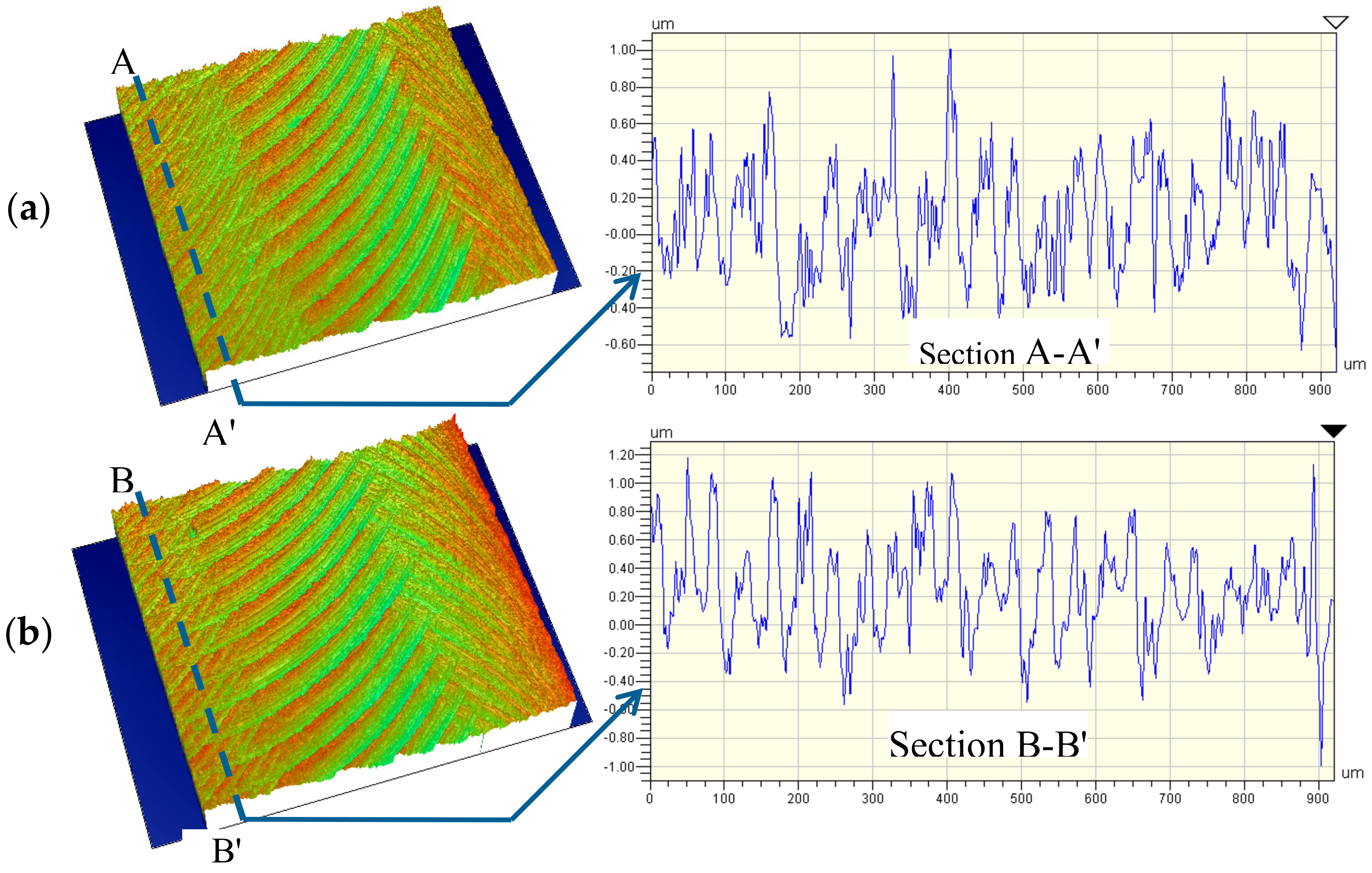
Figure 8 the workpiece topomorphy and the roughness profile of the machined floor surface for feedrate 0.01 mm/tooth under various axial cutting depths are presented. The cutting tool traces are clearly depicted and according to the tool feedrate (0.04 mm/rev) the distance between two successive traces is approximately equal to 40 μm. In the digitized roughness profile, which refers to a length of 0.92 mm, a total of 23 tracks can be identified. This means that at every tool revolution just only one cutter flute path was imprinted on the surface texture. Apparently, each cutting flute takes part in the cutting process, but the eccentric one demonstrates higher force amplitude, which means that the specific flute cuts much more material. The traces of lower depth generated by the other flutes were removed because of the dominating flute path, leaving on the surface only one trace per tool revolution. Additionally, the tool deflection yielded an “axial runout”, where the dominating flute was touching the workpiece more than the others, thus generating the observed bottom marks. Respectively, in
Figure 9 the corresponding surface characteristics for feedrate 0.02 mm/tooth are shown. In this case, as expected, the distance between the successive tool traces amounted to 80 μm.
Table 2 shows the results of the maximum roughness value R
t of the roughness profile concerning the machined floor surface under three axial cutting depths. Each of the results represents the mean value of R
t (
) for 10 profiles measured in the feed direction.
By increasing the axial cutting depth, the workpiece roughness becomes higher. At the same time an enhancement of the tool feedrate results in an additional increment of the workpiece roughness. This is expected since by increasing the volume of removed material the main cutting force increases too, leading to cutting tool deflection, which yields higher roughness.
In
Figure 10 the topomorphy of the machined workpiece floor surface is presented in detail (zoom ×50). It can be observed that waviness is formed on the workpiece surface inside the cutting tool path (see figure detail). This waviness has occurred due to the tool vibration during the cutting process. The tool was subjected to high vibrations, as a result of the relatively high cutting forces, because of the tough cutting conditions of the specific experiment in relation to the others.
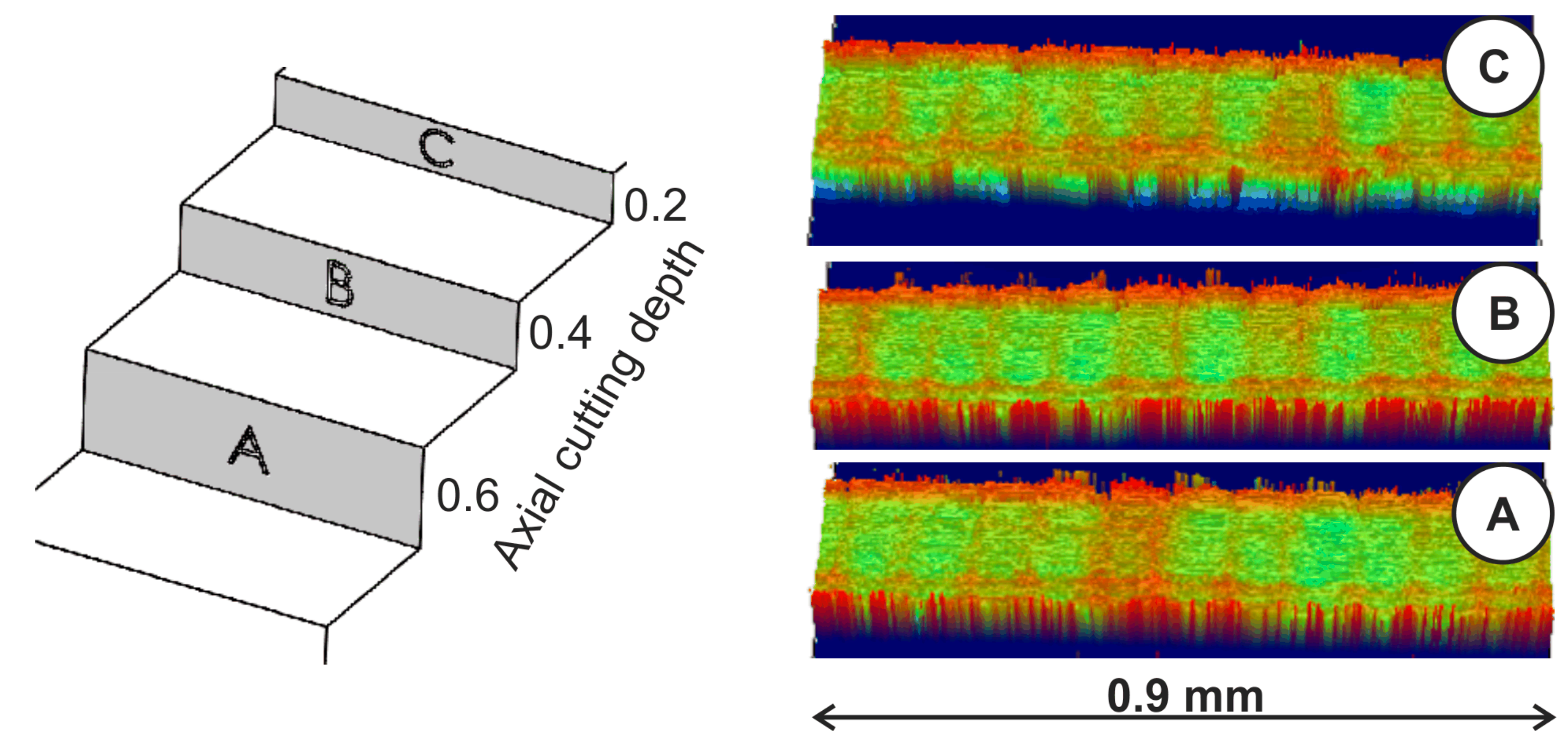
In
Figure 11, the workpiece topomorphy of the machined wall surface is illustrated for a tool feedrate of 0.02 mm/tooth and axial cutting depth of 0.2, 0.4 and 0.6 mm. The cutting tool traces due to the tool kinematics are shaped in the form of waves at each tool revolution. Observing the number of the waves at the examined length, the cutting tool feedrate can be validated. That means that in a length of about 0.9 mm, 11 waves appears with a wavelength of 80 μm, which is equal to the cutter feed per revolution (0.08 mm/rev). This means that just one cutting edge per tool revolution dominates in the cutting process because of the cutter runout effect. The waviness profile height depends on the axial depth of cut because of the superimposed cutter declination and cutter runout.
4. Conclusions
In profile end-milling processes, the excitation mechanisms that take place in the cutting area between the cutting tool and the workpiece need to be carefully studied in order to ascertain the factors that affect the cutting operation. The present paper examines the effect of cutter runout on cutting forces and, thereby, on the workpiece topomorphy in cases where cutting tools of a few millimeters scale diameter are implemented in end-milling operations.
Specific experiments under various cutting conditions were conducted, whereby the cutting forces were recorded and appropriately processed. The results revealed that the cutting forces increased with the tool feedrate. Moreover, a rise of the axial cutting depth which resulted in a higher metal removal rate can cause more intense tool excitation, thus leading to vibration phenomena capable of affecting the workpiece surface finish.
In the case of the use of cutters with a residual runout, the topomorphy of the machined workpiece surface was also investigated. Increasing the axial cutting depth led to a higher surface roughness. Moreover, the surface roughness became worse with a higher tool feedrate. The experimental results have revealed that a direct correlation between the cutting conditions and both the workpiece topomorphy and the surface roughness exists.
In the case that a residual cutter runout is present, it has been verified that one cutting flute per tool revolution mostly takes part in the cutting process. Furthermore, evaluation of the machined workpiece topomorphy in end-milling process provides useful information about the effect of the vibration phenomena caused by cutter runout. To this end, the findings of this research can serve as useful suggestions for machinists who are confronting problems caused by tool runout.
Author Contributions
Conceptualization, C.D. and D.S.; Methodology, C.D. and D.S.; Software, D.S. and C.T.; Validation, C.D., D.S. and Ι.Τ.; Formal Analysis, C.D. and Ι.Τ.; Investigation, C.D., D.S. and E.S.; Resources, C.D., D.S., E.S., C.T. and Ι.Τ.; Data Curation, C.D. and D.S.; Writing-Original Draft Preparation, C.D., D.S. and E.S.; Writing-Review & Editing, C.D. and D.S.; Visualization, D.S.; Supervision, C.D.; Project Administration, C.D.
Funding
This research received no external funding.
Conflicts of Interest
The authors declare no conflict of interest.
References
- Altintas, Y. Manufacturing Automation—Metal Cutting Mechanics, Machine Tool Vibrations and CNC Design, 2nd ed.; University of British Columbia: Vancouver, BC, Canada; Cambridge University Press: Cambridge, UK, 2012. [Google Scholar]
- David, C.; Sagris, D.; Stergianni, E.; Tsiafis, C.; Tsiafis, I. Experimental analysis of charter vibration on micro milling. Ann. Constantin Brancusi Univ. Targu-Jiu Jurid. Sci. Ser. 2016, 4, 210–216. [Google Scholar]
- Dornfeld, D.; Min, S.; Takeuchi, Y. Recent advances in mechanical micromachining. CIRP Ann. Manuf. Technol. 2006, 55, 745–768. [Google Scholar] [CrossRef]
- Quintana, G.; Ciurana, J. Chatter in machining processes: A review. Int. J. Mach. Tools Manuf. 2011, 51, 363–376. [Google Scholar] [CrossRef]
- Schmitz, T.L.; Smith, K.S. Machining Dynamics Frequency Response to Improved Productivity; Springer Science and Business Media, LLC: Berlin/Heidelberg, Germany, 2009. [Google Scholar]
- Altintas, Y. Research on metal cutting, machine tool vibrations and control. J. Jpn. Soc. Precis. Eng. 2011, 77, 470–471. [Google Scholar]
- Stergianni, E.; Sagris, D.; Tsiafis, C.; David, C.; Tsiafis, I. Influence Analysis of micro-milling vibrational phenomena on workpiece topomorphy. Solid State Phenom. 2017, 261, 77–84. [Google Scholar] [CrossRef]
- Rivière-Lorphèvre, E.; Filippi, E. Mechanistic cutting force model parameters evaluation in milling taking cutter radial runout into account. Int. J. Adv. Manuf. Technol. 2009, 45, 8. [Google Scholar] [CrossRef]
- Oliaei, S.N.B.; Karpat, Y. Experimental investigations on micro milling of stavax stainless steel. Procedia CIRP 2014, 14, 377–382. [Google Scholar] [CrossRef]
- Matsumura, T.; Tamura, S. Cutting force model in milling with cutter runout. Procedia CIRP 2017, 58, 566–571. [Google Scholar] [CrossRef]
- Koenig, W.; Klocke, F. Fertigungsverfahren 1: Drehen, Fräsen, Bohren; Springer-Verlag: Berlin/Heidelberg, Germany, 2002; ISBN 3-540-43304-X. [Google Scholar]
- Wojciechowski, S.; Twardowski, P.; Wieczorowski, M. Surface texture analysis after ball end-milling with various surface inclination of hardened steel. Metrol. Meas. Syst. 2014, 21, 145–156. [Google Scholar] [CrossRef]
© 2018 by the authors. Licensee MDPI, Basel, Switzerland. This article is an open access article distributed under the terms and conditions of the Creative Commons Attribution (CC BY) license (http://creativecommons.org/licenses/by/4.0/).

 ,
, 


