Article

Research on PCBN Tool Dry Cutting GCr15

College of Machinery and Vehicle Engineering, Changchun University, Changchun 130022, China
*
Author to whom correspondence should be addressed.
Machines 2018, 6(3), 28; https://doi.org/10.3390/machines6030028
Submission received: 3 May 2018 / Revised: 27 June 2018 / Accepted: 28 June 2018 / Published: 1 July 2018
(This article belongs to the Special Issue Advanced Control Systems and Optimization Techniques)

Abstract

:
This paper is based on the theoretical analysis designs of a dry cutting orthogonal test in order to study a phenomenon that the radial force is larger than the main cutting force when a PCBN (polycrystalline cubic boron nitride) tool hard turns GCr15. Finite element modelling and cutting tests show the cutting depth and the spindle speed having an impact on the main cutting force, the radial force, and the axial force. In this study, due to the shear function of the cutting process, the squeezing effect between the tool and the workpiece, and the metal softening effect of the workpiece material, the different cutting depth and the spindle speed bring about different cutting force changes, and also different spindle speeds have different effects on the three components of the total cutting force. The research result provides a basis for further study on dry turning of hardened bearing steel.

1. Introduction

With the advent of high hardness and difficultly-machined materials, the demand for cutting tools becomes higher and higher. PCBN (polycrystalline cubic boron nitride) tools are widely used in hard turning because of excellent cutting performance. Hard turning has developed for more than 20 years, there are many approaches to study hard turning. Many scholars have conducted a great deal of analysis and discussions on the research of hard turning. Xia et al. found the cutting force first increased obviously with the increase of the chamfered width, then decreased obviously, and finally increased slowly; they concluded the chamfered width had the most significant influence on the radial force [1]. Wu et al. found the cutting force showed nonlinear changes with the PCBN tools’ negative chamfer changing, and it was recommended to use a 15 degree negative chamfer in actual production so that the cutting force could be reduced properly [2]. Gao and An found the cutting depth had the greatest influence on the cutting force when a CBN tool cut Cr12MoV [3]. Pereira et al. used of combined technique based on cryogenic cooling and a minimum quantity of lubrication, which was proposed and compared with other near-to-dry coolant alternatives [4]. Additionally, Pereira et al. who proposed the cryoMQL technology, developed a CO2 cryogenic regulation system and a nozzle adaptor while milling Inconel 718 [5]. Lamikiz et al. presented a method for obtaining the shear and ploughing specific cutting coefficients for a ball-end milling cutting force model, which was applied to 7075-T6 aluminum alloy and 52HRC AISI H13 tool steel [6]. Fernández-Abia et al. presented a mechanistic model for cutting force prediction, and this model was developed for machining with nose radius tools considering the effect of the edge force due to the rounded cutting edge. They concluded that shearing and edge cutting coefficients were valid for a wide range of cutting conditions [7].
The hardened bearing steel GCr15, as a difficultly-processed material, has a hardness of 56HRC to 66HRC after quenching and tempering treatment, and whose Rockwell hardness decreases with the increase of the tempering temperature (from HRC 61.7 of 165 °C to HRC 56.2 of 300 °C) [8]. Therefore, GCr15 belongs to the hard machined materials with high hardness, and the machinability of GCr15 is widely studied. At present, the tool materials cutting GCr15 include carbide cutting tools, ceramic cutters, and cubic boron nitride cutters, etc. For example, Liang and Zhao used a hard YBC251alloy blade to cut GCr15, the results showed that the feed and the tool corner radius had great influence on the surface quality of GCr15 [9]. Tu et al. studied the tool wear performance of dry cutting GCr15 through different materials, such as CC6050ceramics, cubic boron nitride, and CB7025 and GC2025 carbide [10]. Additionally, the study of the cutting force produced in the process of cutting GCr15 have been a problem that has aroused numerous discussions amongst scholars. Qiu et al. studied the cutting force generated by high-speed cutting GCr15 with a PCBN tool, and it was found that cutting force increased along with the increase of the cutting speed, the cutting depth, and the feed [11]. Xiao and Wen found that the cutting speed had a critical value with respect to the influence on cutting temperature, cutting force, and surface roughness, and also found that increasing the cutting speed could reduce the cutting force when the PCBN tool cuts GCr15 [12].
However, when the hardness of the workpiece is higher than that of 55HRC, the cutting mechanism will change, which leads to a significant change in the cutting force. When PCBN tools are used to turn hard materials whose hardness is over 55 HRC, the main cutting force will be lower than the radial force. Recently studies have shown the radial force is larger than the main cutting force when the dry finish of Inconel 718 is turned by PCBN tools. Cantero et al. argued that the radial force values were high with respect to the rest of the specific cutting force components due to the premature cutting edge deterioration [13]. Moreover, Fernández-Valdivielso et al. also found that force was directly related with flank wear for all the inserts when detecting the key geometrical features and grades of carbide inserts for the turning of nickel-based alloys concerning surface integrity, they found that force grew in the module with wear, especially the radial force presented a higher increment [14]. Furthermore, Li et al. deemed the cutting depth was the main factor affecting the radial force and found the radial force was greater than the main cutting force when the PCBN tools turn GCr15 [15]. Additionally, other scholars also found the same phenomenon when GCr15 was turned by PCBN tools [16,17,18].
However, there is no clear explanations regarding the phenomenon that the radial force is greater than the main cutting force during the process of PCBN tool hard turning of GCr15. Therefore, in order to clarify the reasons, this paper, based on finite simulation and cutting tests, designs orthogonal test methods and makes systematic theoretical analyses from the tool shear function and the metal softening effect of the workpiece material.

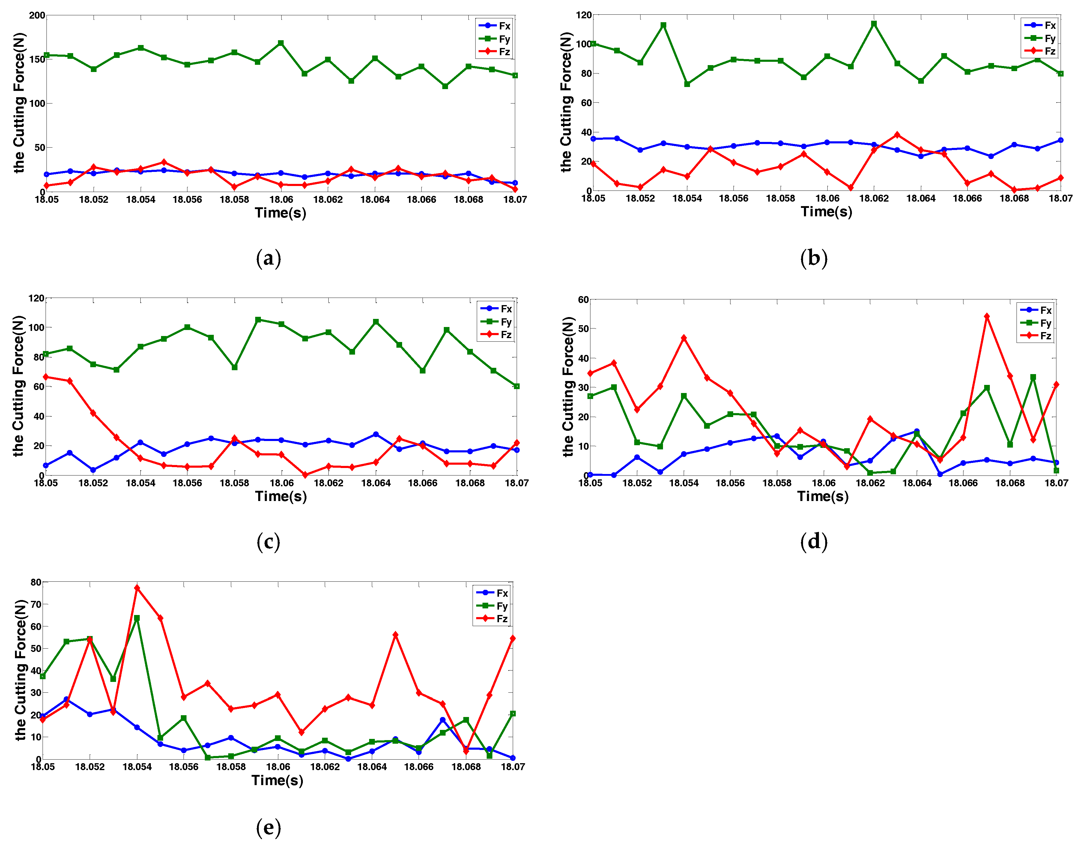
2. The Test for Cutting Force

2.1. The Test of Equipment

The test using PCBN tools to cut GCr15 is carried out on a CNC lathe. The cutting force measurement system used in this cutting test consisted of the KISTLER 2825 A-02 type high-sensitivity piezoelectric three-direction dynamometer which is made in Switzerland, the 5070Ax01xx type four-channel charge amplifier, the DynoWare System data acquisition software, an A/D conversion card, the host, and the display system. The main measuring principle is the preliminary measurement in the cutting process through the three-direction accelerometer mounted on the tool carrier. The generated signals were measured by the charge amplifier, data acquisition card, and data acquisition and processing software, using various graphical display functions of the system to measure the cutting force. Finally, the measurement data were analyzed and studied. The hardness of GCr15 is detected by an HR-150A Rockwell hardness tester.

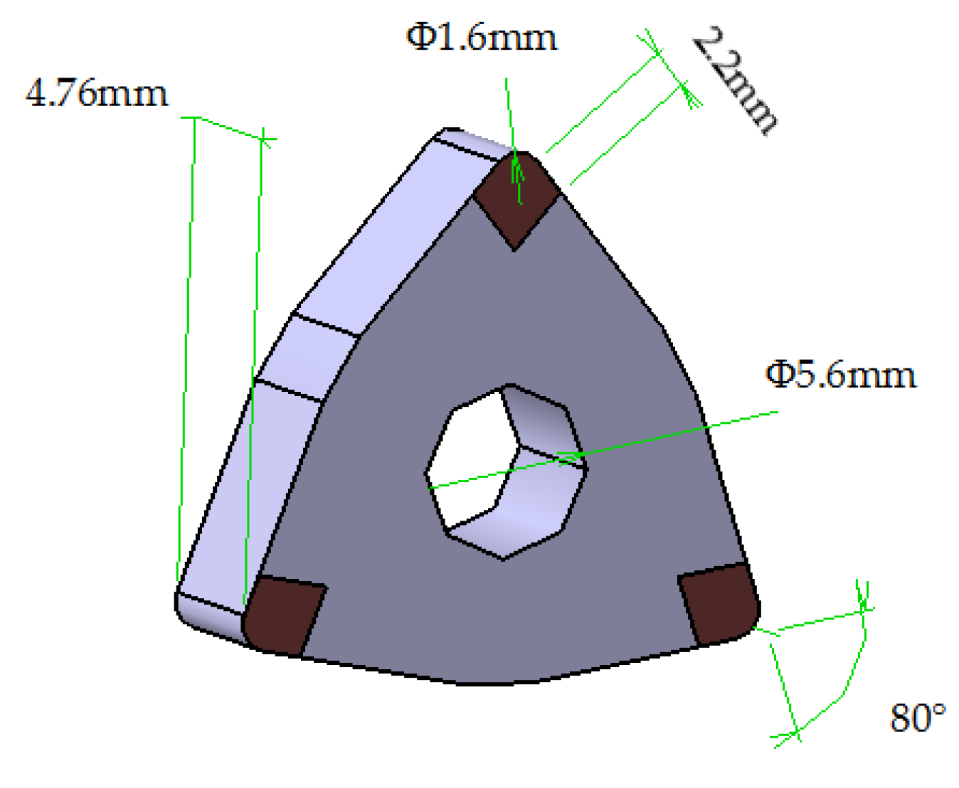
2.2. Workpieces and PCBN Tools

The workpiece material is GCr15 bearing steel and its diameter is 48 mm. After quenching and heat treatment, the hardness is 58 ± 2 HRC after being tested by the Rockwell hardness tester.
The tool used for the test is a WNGA080408 PCBN tool. As shown in Figure 1, the practical working parameters of the tool are shown in Table 1.

2.3. The Test Programme

The test is carried out to study the effects on the main cutting force Fz, the axial force Fx and the radial force Fy under the different cutting depths and the varied spindle speed (the cutting speed). Additionally, the analysis that the radial force Fy is greater than the main cutting force Fz is significant.
Programme 1: the feed has been already set to f = 0.1 mm/r, setting the spindle speed to n = 500 r/min, and setting the back cutting depth ap to 0.1 mm, 0.2 mm, 0.3 mm, 0.4 mm, 0.5 mm , which analyzes and researches the phenomenon that the radial force Fy is greater than the main cutting force Fz;
Programme 2: On the basis of Programme 1, the spindle speed is set to n = 220 r/min, n = 355 r/min, and the back cutting depth is set ap = 0.3 mm, 0.4 mm, 0.5 mm ; there is a further study of Programme 1 and analysis of the influence of different spindle speeds (the cutting speed) on each cutting force.

3. Element Model and Analysis

3.1. Material Constitutive Model

The Johnson-Cook constitutive model is a constitutive model related to the strain rate, which describes the behavior of the thermal viscoplastic deformation of the material at a high strain rate, and mainly takes into account the strain rate effect of the flow stress. The Johnson-Cook constitutive model shows that the material is changed into strain hardening, strain rate hardening, and thermal softening effects at a high strain rate. It is widely used in the field of mechanical cutting.
The empirical formula of the Johnson-Cook constitutive model is:
σ = [ A + B ( ε ) n ] [ 1 + C ln ( ε ˙ p ε ˙ 0 ) ] ( 1 ( T T 0 T m T 0 ) m )
where A, B, c, n, and m are material parameters. σ is the flow stress of material, ε is the equivalent plastic strain, ε ˙ p is the equivalent plastic strain rate, ε ˙ 0 is the strain rate reference value, T is the deformation temperature, T0 is the room temperature, and Tm is the melting point temperature of material.
Table 2 shows the Johnson-Cook constitutive model parameter of GCr15, Table 3 shows the GCr15 mechanical and physical properties, and Table 4 shows the mechanical and physical properties of the PCBN tool.

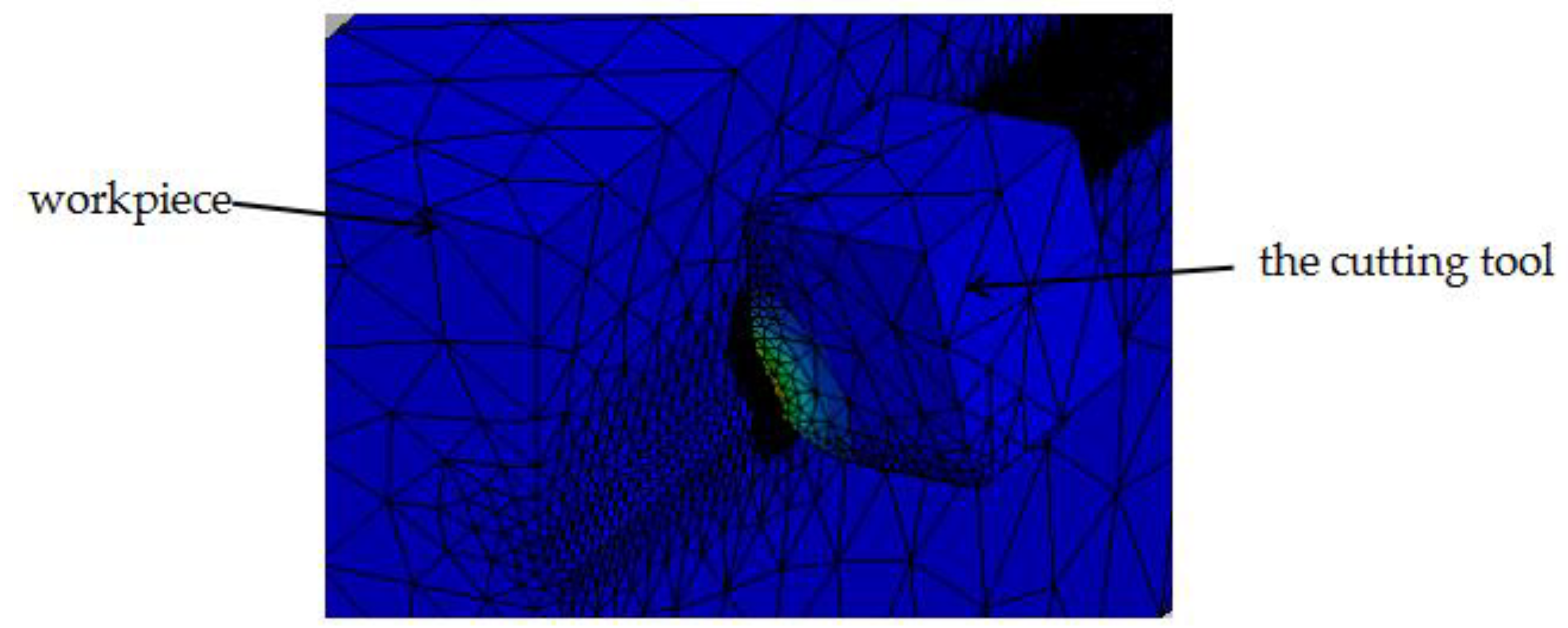
3.2. Finite Element Model

As shown in Figure 2, a finite element model for the cutting tool and workpiece is presented. Adaptive grid partition is used for the tool and workpiece. Firstly, the cutting edge is the main cutting part. Therefore, the mesh density is very intensive, which helps to study the cutting condition of the cutting tool. In the cutting surface of the workpiece, its mesh is also denser, and the rest of the mesh is relatively sparse.

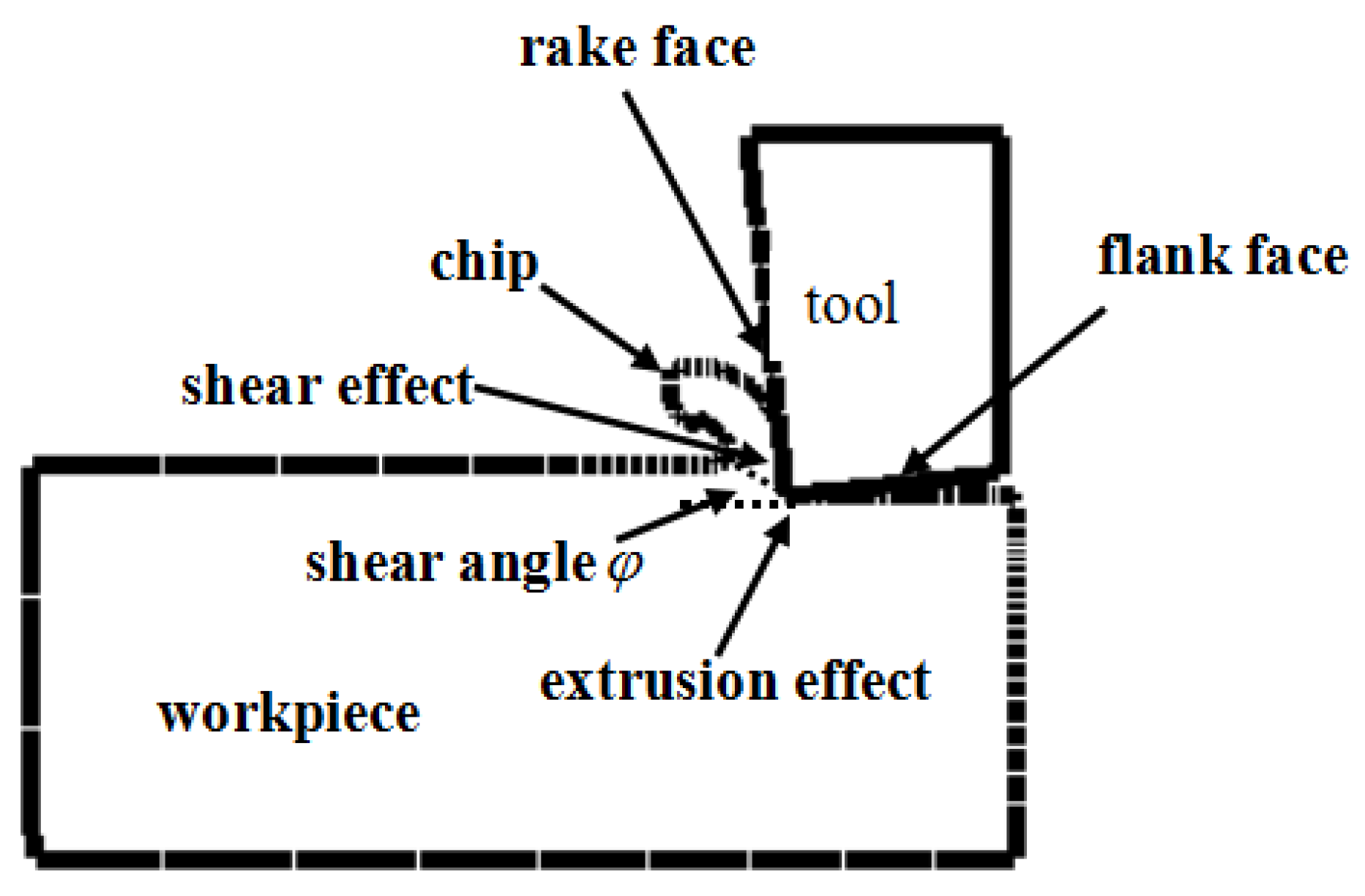
3.3. Finite Element Analysis

Figure 3 shows the distribution of the main cutting force, radial force, and axial force in the finite element simulation under different cutting depths. As shown in Figure 3a, the radial force Fy is larger than the main cutting force Fz and the axial force Fx under lower cutting depths. However, when the cutting depth becomes larger, for example, increasing to 0.5 mm, the main cutting force Fz becomes larger than the radial force Fy. This phenomenon in the simulation is the same as the above literature [15,16,17,18].

4. Analysis of Cutting Test’s Results

According to the cutting force obtained from the simulation, the PCBN tool turning GCr15 test is carried out, which is based on the design test Programmes 1 and 2. Additionally, analysis is made from the theory of the metal softening effect and shear effect.

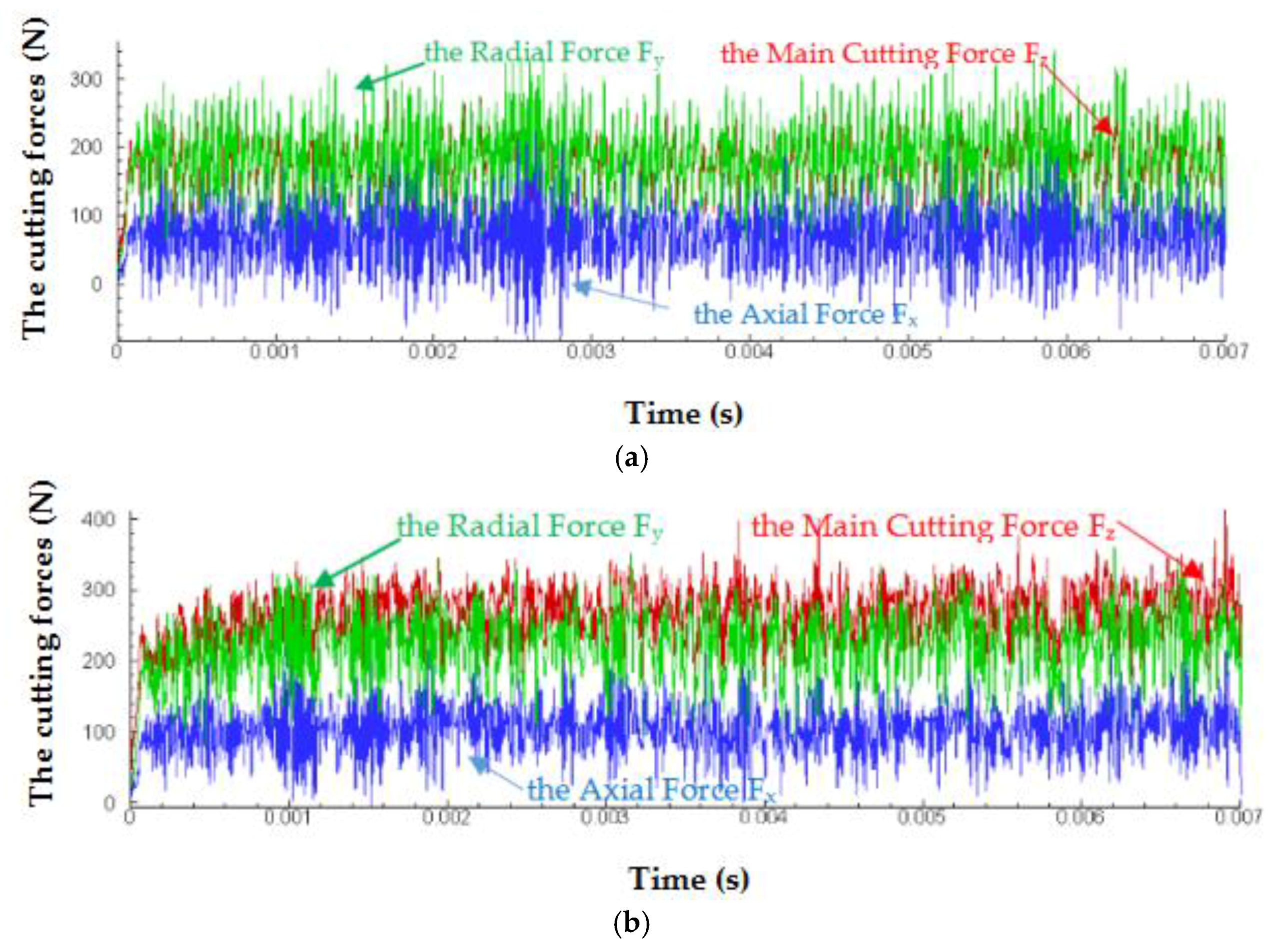
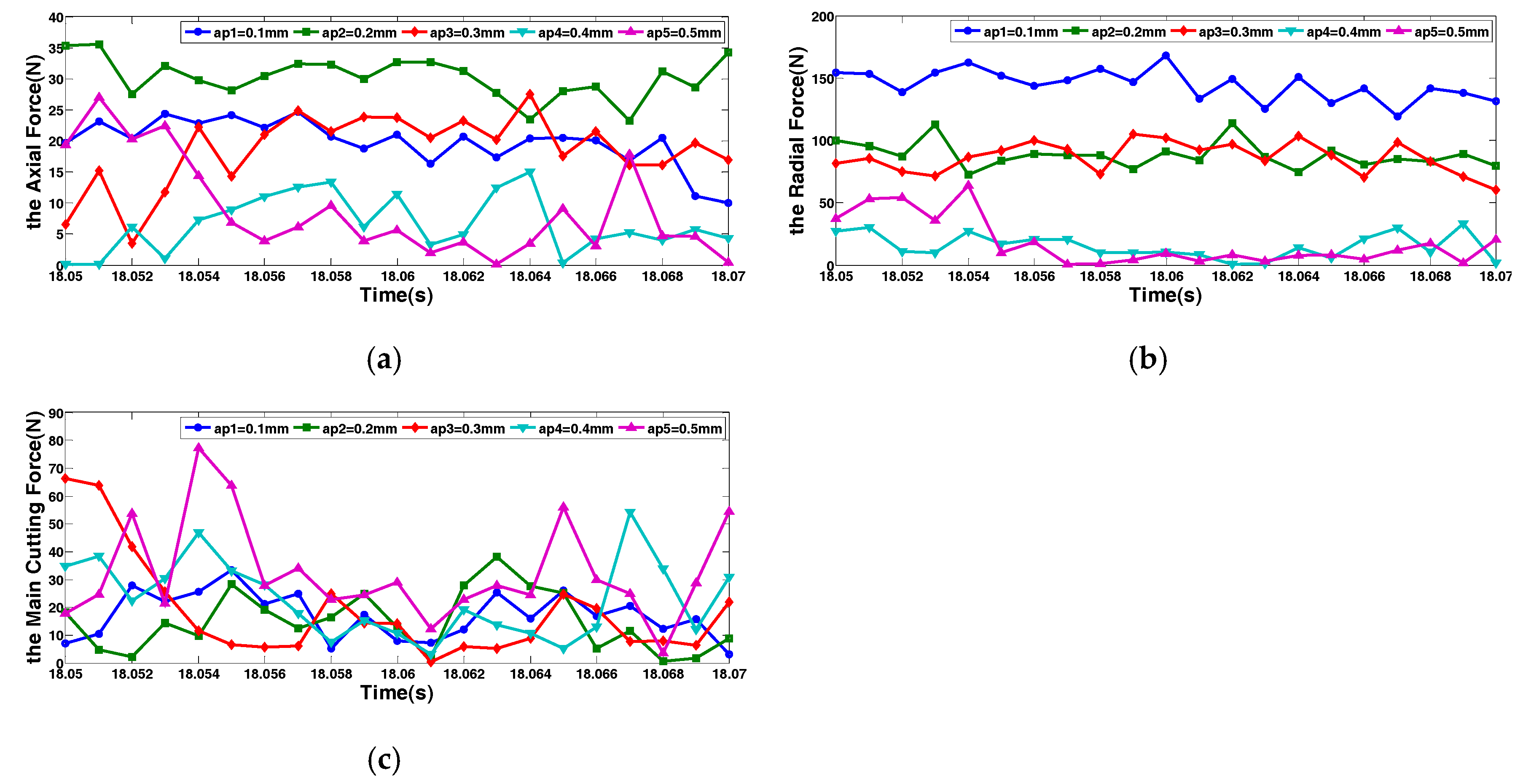
4.1. Analysis of Programme 1

Figure 4 is a sketch of the cutting tool and the workpiece. In the actual cutting process, a KISTLER dynamometer is used to collect the data. Figure 5 depicts that the spindle speed is unchangeable, which shows the influence of the different back cutting depth for each cutting force. Figure 5 shows the changes of the main cutting force Fz, the axial force Fx, and the radial force Fy under the different cutting depth conditions. There is a further analysis of the data: when the back cutting depth ap = 0.1 mm~ 0.3 mm, the radial force Fy is much larger than the main cutting force Fz and the axial force Fx. When the cutting depth is ap = 0.4 mm, there is a trend of reclosing between the radial force Fy and the main cutting force Fz. As he cutting depth increases, the main cutting force Fz gradually grows larger than the radial force Fy, which is the same as the simulation and the previous literature [15,16,17,18]. When the cutting depth ap is smaller, the contact length of the cutting edge and the radial direction become smaller in the tangential direction of the cutting edge, the surface of the workpiece will form a scratch, and the cutting edges obtuse radius in the radial direction causes a more serious extrusion on the machined surface. The extrusion effect becomes the main factor causing the change of the cutting force, which triggers the radial impact force to be too large. It can be seen from that the comprehensive effect of plow and extrusion has a great influence on the radial force, causing a large radial force Fy. According to Figure 4 and Figure 5, further analysis shows that in the cutting process, due to the cutting depth ap being small, the shear effect becomes weakened, the shear angle ϕ becomes large, and the influence of the tool tip impact on the main cutting force weakens, which leads to the main cutting force Fy becoming smaller, while the extrusion effect between the tool and the workpiece is greater than that of the shearing, which leads to the radial force Fy becoming larger and greater than the main cutting force Fz. However, with the increase of the cutting depth, the strengthening shear causes the main cutting force Fz to be larger, and the effect of extrusion weakens the radial force Fy, so the main cutting force Fz is greater than the radial force Fy.
Figure 6 shows the curve that each cutting force is affected by the cutting depth under the spindle speed n = 500 r/min. From Figure 4 it can be determined that, with the increase of the cutting depth, the change in the axial force Fx ascends firstly, and then drops, while the radial force Fy reduces and, oppositely, the main cutting force Fz shows a rising trend. The change of the cutting force also confirms that for the smaller cutting depth ap, the radial force Fy is greater than the main cutting force Fz. Nevertheless, the increase of the cutting depth makes the radial force Fy decline, which causes that the main cutting force Fz to be greater than the radial force Fy. Additionally, relative to the main cutting force, the influence of the cutting depth on the radial force is more serious.

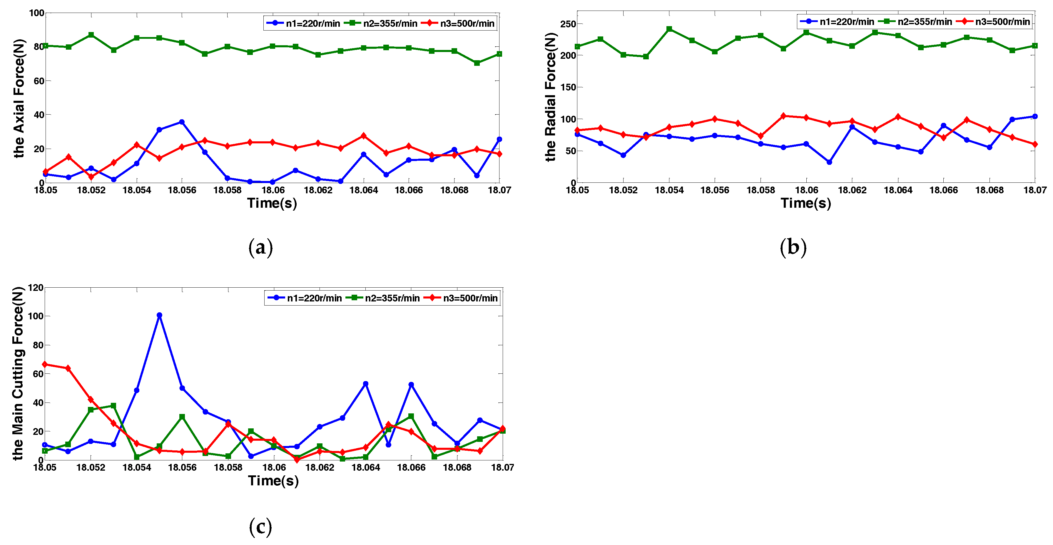
4.2. Analysis of Programme 2

Based on Programme 1, the test is repeatedly carried to study the influence that the varied spindle speed (the cutting speed) has an impact on each cutting force under the fixed feed and the invariable cutting depth. The spindle speed is set to n = 220 r/min, n = 355 r/min, and the cutting depth is set ap = 0.3 mm ~ 0.5mm. Figure 5 is the curve of each cutting force in the range of the spindle speed n = 220 r/min ~ 500 r/min, when the cutting depth is ap = 0.3 mm. It can be seen from Figure 7 that the axial force Fx and the radial force Fy are both increasing, firstly, and then reducing, yet the main cutting force Fz tends to dwindle. The spindle speed has a greater influence on the axial force and radial force than the main cutting force.
When the cutting depth is ap = 0.4 mm, 0.5 mm, and the spindle speed is n = 220 r/min ~ 500 r/min, all of the results present that the cutting force decreases. This is because the increase of the spindle speed directly affects the increase of the cutting speed, which leads to the increase of the cutting temperature. At a higher temperature, the metal softening effect will occur on the surface material of the GCr15workpiece, in which the hardness of the workpiece in the high-temperature area is reduced, and the yield strength of the material decreases. The high temperature can decrease the coefficient of friction and the deformation of the workpiece. When the coefficient decreases, the shear angle is larger, and the plastic deformation degree of the workpiece is reduced, thus, the cutting force is reduced.
The test results of Programme 1 and Programme 2 are basically the same, that is, under the condition of the smaller cutting depth, the radial force is larger than the main cutting force, whereas the main cutting force starts to increase the radial force with the increase in the cutting depth.

5. Conclusions

In the process of machining, cutting is an extremely complex process, which has both shear effect and mutual extrusion friction. These factors have a very important impact on the cutting force. The following conclusions are drawn from the above analysis on PCBN tools dry cutting hardened GCr15bearing steel.
(1) Under smaller cutting depths, the radial force generated in the cutting process is greater than that of the main cutting force and the axial force. With the increase of the cutting depth, the main cutting force increases, while the radial force decreases, which causes the main cutting force to be greater than the radial force. This is because the cutting depth is smaller, and the radial contact length of the tool and the workpiece is smaller. Serious extrusion and the increase of radial force causes the radial force to be greater than the main cutting force. However, with the increase of the cutting depth, the shear strength is strengthened, and the main cutting force is greater than the radial force.
(2) The effective degree of the cutting depth on the axial force, the radial force, and the main cutting force are different. The result of increasing the cutting depth triggers the radial force to decrease, the main cutting force tends to increase, and the axial force increases firstly, and then decreases.
(3) When the cutting depth is constant, the increase of the spindle speed causes the axial force and the radial force to increase firstly, and then decrease, while the main cutting force decreases. The above results indicate that increasing spindle speed (the cutting speed) is conducive to reducing the cutting force, lengthening tool life, improving machining quality, and reducing machining cost.

Author Contributions

Q.L. provided the conceptualization, funding acquisition, methodology, and resources. C.P. conceived and designed the experiments, and provided the data curation, formal analysis, methodology, project administration, and writing of the original draft; Y.J. provided the software, supervision, and review and editing of the manuscript; and K.H. provided the project administration, software and writing of the original draft.

Funding

This research received no external funding.

Conflicts of Interest

There is no conflict of interests between all authors.

References

  1. Xia, X.; Wang, Q.; Yang, H. Effect of Chamfered Width of PCBN Tool on Cutting Force. Tool Eng. 2017, 51, 34–35. [Google Scholar]
  2. Wu, M.; Tian, Z.; Yu, Y.; Hao, P.; Cheng, Y. Experimental Study on Cutting Force in Turning Superalloy by PCBN Cutting Tool. Aeronaut. Manuf. Technol. 2017, 22, 101–105. [Google Scholar]
  3. Gao, S.; An, L. Finite Element Simulation of Cutting Force Using Cubic Boron Nitride Cutting Tools in Dry Hard Turning Conditions. Mach. Design Res. 2016, 32, 131–134. [Google Scholar]
  4. Pereira, O.; Rodríguez, A.; Fernández-Abia, A.I.; Barreirob, J.; de Lacallea, L.N.L. Cryogenic and minimum quantity lubrication for an eco-efficiency turning of AISI 304. J. Clean. Prod. 2016, 139, 440–449. [Google Scholar] [CrossRef]
  5. Pereira, O.; Rodríguez, A.; Ayesta, I.; García, J.B.; Fernández-Abia, A.I.; de Lacalle, L.N.L. A cryo lubri-coolant approach for finish milling of aeronautical hard-to-cut materials. Int. J. Mechatron. Manuf. Syst. 2016, 9, 370. [Google Scholar] [CrossRef]
  6. Lamikiz, A.; Lacalle, L.N.L.D.; Sanchez, J.A.; Bravo, U. Calculation of the specific cutting coefficients and geometrical aspects in sculptured surface machining. Mach. Sci. Technol. 2005, 9, 411–436. [Google Scholar] [CrossRef]
  7. Fernández-Abia, A.I.; Barreiro, J.; Lacalle, L.N.L.D.; Martínez-Pellitero, S. Behavior of austenitic stainless steels at high speed turning using specific force coefficients. Int. J. Adv. Manuf. Technol. 2012, 62, 505–515. [Google Scholar] [CrossRef]
  8. Wang, G. Effect of Tempering Temperature on Microstructure & Properties of GCr15 Bearing Steel. Fail. Anal. Prev. 2016, 11, 361–363. [Google Scholar]
  9. Liang, J.; Zhao, S. Study on Surface Roughness during Turning GCr15 Bearing Steel by Hard Alloy Cutting Tools. Tool Eng. 2014, 48, 90–91. [Google Scholar]
  10. Tu, C.; Guo, X.; Wu, S. Wear Property of Cutting Tools with High Hardness in Dry Turning Hardened Steel. Mater. Mech. Eng. 2013, 37, 55–59. [Google Scholar]
  11. Qiu, H.; Ban, X.; Ji, L.; Wang, M. Study on Simulation and Experiment of Cutting Force in High Speed Cutting GCr15. Modul. Mach. Tool Autom. Manuf. Tech. 2016, 4, 154–157. [Google Scholar]
  12. Xiao, L.; Wen, D. Study on Speed of PCBN Cutting Tools Cutting Bearing Steel. Tool Eng. 2011, 45, 35–36. [Google Scholar]
  13. Cantero, J.L.; Díaz-Álvarez, J.; Infante-García, D.; Rodríguez, M.; Criado, V. High Speed Finish Turning of Inconel 718 Using PCBN Tools under Dry Conditions. Metals 2018, 8, 192. [Google Scholar] [CrossRef]
  14. Fernández-Valdivielso, A.; Lacalle, L.L.D.; Urbikain, G.; Rodriguez, A.; Fernández-Valdivielso, A.; de Lacalle, L.N.L.; Urbikain, G.; Rodriguez, A. Detecting the key geometrical features and grades of carbide inserts for the turning of nickel-based alloys concerning surface integrity. ARCHIVE Proc. Inst. Mech. Eng. Part C J. Mech. Eng. Sci. 2015, 230. [Google Scholar] [CrossRef]
  15. Li, S.; Wang, G.; Han, Z. Experimental study on cutting force on hardened bearing steel in high-speed turning. J. Changchun Univ. Technol. 2017, 38, 231–236. [Google Scholar]
  16. Hao, D. Experpient and analysis on cutting force in turning Cr12 and GCr15. J. Jiangsu Univ. Sci. Technol. 2008, 24, 152–155. [Google Scholar]
  17. Du, G. Experimental Study on GCrl5 Steel Hard-cutting with Ceramic Cutters Cutters. Tool Eng. 2008, 42, 88–90. [Google Scholar]
  18. Ren, S.; Li, M.; Zhang, H.; Li, Y. Effects of PCBN Cutting Tool’s Chamfer Angle on Cutting Property During Process in Interrupted Turning Hardened Steel. Tool Eng. 2010, 44, 13–15. [Google Scholar]
Figure 1. The WNGA080408 PCBN tool.
Machines 06 00028 g001
Figure 2. Tool and workpiece finite element model.
Machines 06 00028 g002
Figure 3. Finite element cutting force: (a) the cutting depth is smaller; and (b) the cutting depth is larger.
Machines 06 00028 g003
Figure 4. Cutting diagram of the cutting tool and workpiece.
Machines 06 00028 g004
Figure 5. The Influence of different cutting depth cutters on the cutting force under the spindle speed n = 500   r / min : (a) ap = 0.1 mm; (b) ap = 0.2 mm; (c) ap = 0.3 mm; (d) ap = 0.4 mm; (e) ap = 0.5 mm.
Machines 06 00028 g005
Figure 6. n = 500   r / min , the change curve of each cutting force under different cutting depths: (a) the axial force F x ; (b) the radial force F y ; and (c) the main cutting force F z .
Machines 06 00028 g006
Figure 7. a p = 0.3   mm , the change curve of each cutting force under different spindle speeds: (a) the axial force Fx; (b) the radial force Fy; and (c) the main cutting force Fz.
Machines 06 00028 g007
Table 1. The practical cutting parameters of the PCBN tool.
Radius of Tool (mm)Rake Angle γ 0 Relief Angle α 0 Tool Cutting Edge Angle κ γ End Cutting Edge Angle κ γ
0.8 mm−6°95°
Table 2. Parameters of the GCr15 Johnson-Cook constitutive model.
A (GPa)B (GPa)cmnT0Tm
1.2041.2080.0360.890.1220 °C1180 °C
Table 3. Mechanical and physical properties of GCr15.
Material PropertiesYoung’s Modulus
(GPa)
Poisson RatioDensity
(g/cm3)
Rockwell Hardness
(HRC)
value2100.37.8558 ± 2
Table 4. Mechanical and physical properties of the PCBN tool.
Material PropertiesYoung’s Modulus
(GPa)
Thermal Conductivity (W/m·K)Poisson RatioDensity
(g/cm3)
Specific Heat
(J/kg·°C)
value6901200.23.8700

