Article

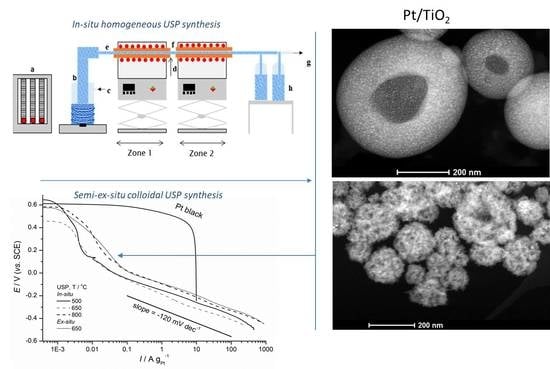
Structural and Electrochemical Properties of Nesting and Core/Shell Pt/TiO2 Spherical Particles Synthesized by Ultrasonic Spray Pyrolysis

by
Milica G. Košević
1,
Milana M. Zarić
1,2,
Srećko R. Stopić
3,
Jasmina S. Stevanović
1,2,
Thomas E. Weirich
4,
Bernd G. Friedrich
3 and
Vladimir V. Panić
1,2,5,*
1
Institute of Chemistry, Technology and Metallurgy, University of Belgrade, National institute, Njegoševa 12, 11000 Belgrade, Serbia
2
Centre of Excellence in Environmental Chemistry and Engineering—ICTM, University of Belgrade, 11000 Belgrade, Serbia
3
IME Process Metallurgy and Metal Recycling, RWTH Aachen University, 52056 Aachen, Germany
4
GFE Central Facility for Electron Microscopy and IFK Institute of Crystallography, RWTH Aachen University, 52074 Aachen, Germany
5
Chemical-Technological Department, State University of Novi Pazar, 36300 Novi Pazar, Serbia
*
Author to whom correspondence should be addressed.
Metals 2020, 10(1), 11; https://doi.org/10.3390/met10010011
Submission received: 15 October 2019 / Revised: 16 December 2019 / Accepted: 17 December 2019 / Published: 20 December 2019
(This article belongs to the Special Issue Advances in Synthesis of Metallic, Oxidic and Composite Powders)

Abstract

:
Pt/TiO2 composites were synthesized by single-step ultrasonic spray pyrolysis (USP) at different temperatures. In an in-situ method, Pt and TiO2 particles were generated from tetra-n-butyl orthotitanate and chloroplatinic acid, and hydrothermally-prepared TiO2 colloidal dispersion served as Pt support in an ex-situ USP approach. USP-synthesized Pt/TiO2 composites were generated in the form of a solid mixture, morphologically organized in nesting huge hollow and small solid spheres, or TiO2 core/Pt shell regular spheroids by in-situ or ex-situ method, respectively. This paper exclusively reports on characteristic mechanisms of the formation of novel two-component solid composites, which are intrinsic from the USP approach and controlled precursor composition. The generation of the two morphological components within the in-situ approach, the hollow spheres and all-solid spheres, was indicated to be caused by characteristic sol-gel/solid phase transition of TiO2. Both the walls of the hollow spheres and the cores of all-solid ones consist of TiO2 matrix populated by 10 nm-sized Pt. On the other hand, spherical, uniformly-sized, Pt particles of a few nanometers in size created a shell uniformly deposited onto TiO2 spheres of ca. 150 nm size. Activities of the prepared samples in an oxygen reduction reaction and combined oxygen reduction and hydrogen evolution reactions were electrochemically tested. The ex-situ synthesized Pt/TiO2 was more active for oxygen reduction and combined oxygen reduction and hydrogen reactions in comparison to the in-situ Pt/TiO2 samples, due to better availability of Pt within a core/shell structure for the reactions.

Graphical Abstract

1. Introduction

Increasingly, a popular topic nowadays is the investigation of fuel cells (FC) as alternative power devices. Many studies have explored possibilities for improving their performance and durability [1,2,3]. Some of the most investigated electrode materials [4,5,6,7] in an FC are platinum-based nanoparticles supported on carbons, due to the high activity of Pt in the kind of reactions FC functioning are based on. Pt can be synthesized in various sizes and shapes, such as spherical [8], cubical [8,9], nanodendritical [10,11], etc. Commonly, the loading of Pt in the cathode of FCs is rather high, at 80—90 mass % [12]. Bearing in mind the low abundance and high cost of platinum, a lot of research aims to reduce the platinum amount in FC catalysts [12,13,14,15,16]. Carbon’s advantages, if compared to other supporting materials, are good conductivity and high surface area [17]. However, the usage of carbon as a Pt support has disadvantages, due its low stability and tendency to corrode [18,19,20]. Namely, the major issue in using carbon-supported platinum as a catalyst is its degradation due to the low stability of carbon during operating and startup/shutdown modes [21]. Carbon degradation, i.e., corrosion, leads to the agglomeration of the supported catalyst particles, which leads to a decrease in catalyst activity. In addition, Pt particle agglomeration and Pt dissolution/re-deposition also contribute to catalyst degradation.
There have been attempts to replace carbon with other more stable and possibly interactive supporting materials [22,23,24,25]. TiO2 is seen as a promising candidate [26,27,28], due to its contribution to stabilization and electroactivity enhancement when used as a Pt support [29,30].
Different methods and conditions of Pt/TiO2 synthesis have been performed in order to improve the characteristics of synthetized material. Since particle size plays an important role in synthesis and catalysis, we compared different types of techniques for synthesis of TiO2 particles and investigated the morphology and structure of obtained material. Various sizes of Pt synthesized within Pt/TiO2 composites are reported in the literature, such as 3.6–6.1 nm in 20 mass % Pt deposited on nano-stick shaped TiO2 [31], 7 nm Pt on TiO2 films [32], and 3 nm-sized Pt in low loading Pt/TiO2 composites (0.1–0.5 mass %) [33]. Pt sized less than 50 nm was deposited on TiO2 nanotubes [34] and 10–20 nm-sized Pt was deposited on alkali-treated nanoporous TiO2 material [35]. In our previous work, Pt/TiO2 composites were synthesized by an ex-situ sol-gel procedure [36].
The goal of this research was to improve the synthesis of Pt/TiO2 electrocatalysts in order to obtain electrocatalytic material of ordered structure. An additional aim was to decrease Pt loading and simultaneously gain good electrocatalytic efficiency for synthesized Pt. Different types of nanoparticle synthesis by ultrasonic spray pyrolysis (USP) have been reported [37,38,39,40,41,42]. In this work, a novel hydrothermally-based USP process for the controlled synthesis of a catalytically-improved catalyst/support ordered structure is reported. The core/shell hierarchy includes active material, such as Pt, deposited in the form of thin layer (e.g., shell) on a core (in our case, TiO2). The core/shell structure enables better utilization of Pt, because it consists of a reactive form of Pt over a less noble core. It is expected that this structure set has an important benefit in decreased Pt loading, because it is uniformly dispersed in locally higher amounts as a thin shell, but is fully operative within a composite shell/support assembly [43]. When a monolayer of Pt is formed over a core, the Pt loading can be significantly reduced [13]. This can contribute to cost reduction in comparison to some commercially available catalysts consisting of 40 mass % (Pt/C HISPEC produced by Johnson Matthey, London, UK, and Pt supported on carbon black by Merck, Kenilworth, NJ, USA) and 50 mass % Pt (Tanaka Kikinzoku Intl., Hiratsuka, Japan). There is a wide range of Pt loading reported in the literature, such as below 5 mass % [33], 5–10 [14,16,44], 20 and 30% [15,45], 30–40 [15,46] 45–50% [14,47].
Although TiO2 by itself is considered inert, it can be interactive due to its synergetic hypo–hyper-d-electronic interactive effect [48]. Furthermore, controlling the synthesis of TiO2 support can favor the core/shell arrangement of the particles, and therefore improve the electrocatalytic properties of Pt/TiO2.
USP in-situ synthesis and ex-situ methods for the synthesis of Pt/TiO2 composites are reported herein. In the in-situ method, TiO2 and Pt are simultaneously synthesized using orthotitanate and H2PtCl6 solutions as precursors. In the ex-situ synthesis, TiO2 was introduced as colloidal dispersion prepared prior to USP synthesis, while Pt was synthesized during the USP synthesis from a H2PtCl6 solution. The USP synthesis enabled the generation of multi-component fully-ordered core/shell composites. The ex-situ synthesis process is expected to give better control of the structure of TiO2 support using the USP methodology and colloidal TiO2, previously synthesized by forced hydrolysis procedure. The morphology, structure, and electrochemical behavior of different set of synthesized particles have been tested. Cyclic voltammetry and linear sweep voltammetry have been performed to test the electrochemical properties of synthesized Pt/TiO2. The activity of the synthesized material for oxygen reduction reaction (ORR) and combined ORR and hydrogen evolution reaction (HER) have been checked.

2. Materials and Methods

2.1. Material Synthesis and Preparation

2.1.1. Synthesis of the Pt/TiO2 Powders

Two sets of experiments were performed in order to synthesize the Pt/TiO2 composites. In the ex-situ synthesis, TiO2 colloidal dispersion, which is hydrothermally prepared from TiCl3 solution (Sigma-Aldrich) [36], and 2.0 g·dm−3 chloroplatinic acid were used as precursors. The TiO2 colloid was prepared by adding TiCl3 solution dropwise into a boiling HCl solution. During the 90 min of boiling of the mixture under reflux, TiO2 particles were generated. The concentration of solid TiO2 in the obtained colloidal dispersion was adjusted to 0.4 g·L−1 using ultrafiltration upon dilution with water to pH 4.0.
In the in-situ synthesis, the mixture of 0.1 mol·dm−3 tetra-n-butyl orthotitanate (Merck) stabilized by hydrochloric acid, and 2.0 g·dm−3 chloroplatinic acid (Alfa Aesar) served as the precursor solution.
Both sets of syntheses, i.e., in-situ and ex-situ, were performed at three different temperatures typical for the USP procedure and equipment: 500, 650, and 800 °C [49,50]. In addition, nominal Pt loadings of 5 and 20 mass % were projected at every synthesis temperature. The precursors for TiO2 and Pt were mixed to give Ti:Pt mole ratios of 50:1 and 10:1 for 5 and 20 mass % Pt, respectively. The mixture was introduced into the ultrasonic spray pyrolysis equipment, as seen in Figure 1 (the details are described in a previously published paper [51]). Only the samples which showed electrochemical activity were subjected to structural characterization, as described in Section 2.2.1.
During the USP synthesis of spray pyrolysis, precursors were driven in the first zone by N2 with the flow of 1.0 L·min−1 through a two-tube furnace upon ultrasonic atomization (Gapusol 9001, RBI atomizer, Meylan, France, operating at 2.5 MHz). In the second zone, H2 is introduced with the flow of 1.0 L min-1 for the Pt reduction to take part. This results in an N2 flow with 1.0 L·min−1 in the first zone, and a mixture of N2 and H2 flow with 2.0 L·min−1 in the second zone. The tube furnaces were pre-heated to the targeted temperature. Synthesized particles were collected in collector bottles filled with ethanol.

2.1.2. Preparation of Pt/TiO2 Coating on Glassy Carbon from Synthesized Powders

Powders collected in the bottles filled with ethanol where centrifuged at 10,000 rpm for 3 min and separated from the ethanol. Obtained precipitates were dried at 90 °C for 24 h in air. In order to check if there were any residues in powders, from either the ethanol or precursors, which could have an impact on the electrochemical response, a part of the obtained powders was washed with water and thermally treated in N2 for 3 h. All of synthesized powders were suspended in water and ultrasonically homogenized during 1 h (40 kHz, 70 W), in order to obtain suspensions of 3 mg·cm−3. Suspensions were deposited onto a glassy carbon (GC) disc in the form of a 0.31 mg·cm−2 thin layer. The applied suspension was left to dry at room temperature. The deposited layer was stable and showed good adhesion to GC, hence there was no need to use any binder. The prepared electrode served as a working electrode.

2.2. Material Characterization

2.2.1. Composition, Morphology, and Structural Characterization

The morphology and elemental composition of the synthesized powders were analyzed by scanning transmission electron microscopy, STEM Tecnai F20 (FEI Company, Eindhoven, The Netherlands) and a system (EDAX Inc., Mahwah, NJ, USA) equipped with energy dispersive spectroscopy (EDX) operated at 200 kV for the analysis of characteristic X-ray emissions. Particle size was analyzed from the recorded STEM images by Image J 1.40 software, (University of Wisconsin, Madison, WI, USA), and the average values with standard deviations are reported.

2.2.2. Electrochemical Characterization

The cyclic voltammetry (CV) and linear sweep voltammetry (LSV) measurements were performed in 100 mL of 1 mol·dm−3 H2SO4 (pH close to zero), at room temperature, in a three-compartment electrode cell that consisted of a platinum plate as a counter electrode, saturated calomel electrode (SCE) or Ag/AgCl as a reference electrode (all potentials in this paper are given in SCE scale) and working electrode. The electrolyte was saturated with oxygen gas for LSV measurements. Cyclic voltammograms and polarization curves were obtained at scan rates of 50 and 1 mV·s−1, respectively. All measurements were performed at ambient temperature using Bio-Logic SAS, potentiostat/galvanostat, model SP-200, (BioLogic Science Instruments, Seyssinet-Pariset, France).

3. Results and Discussion

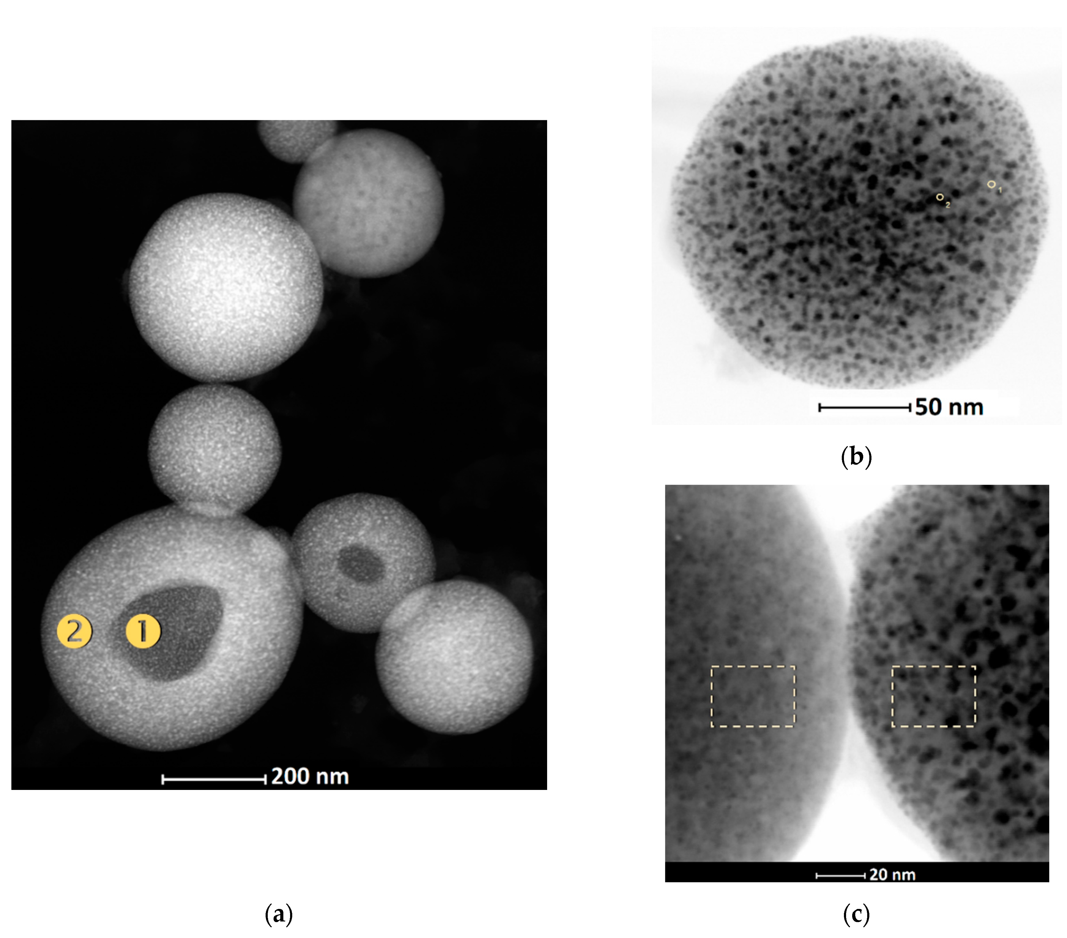
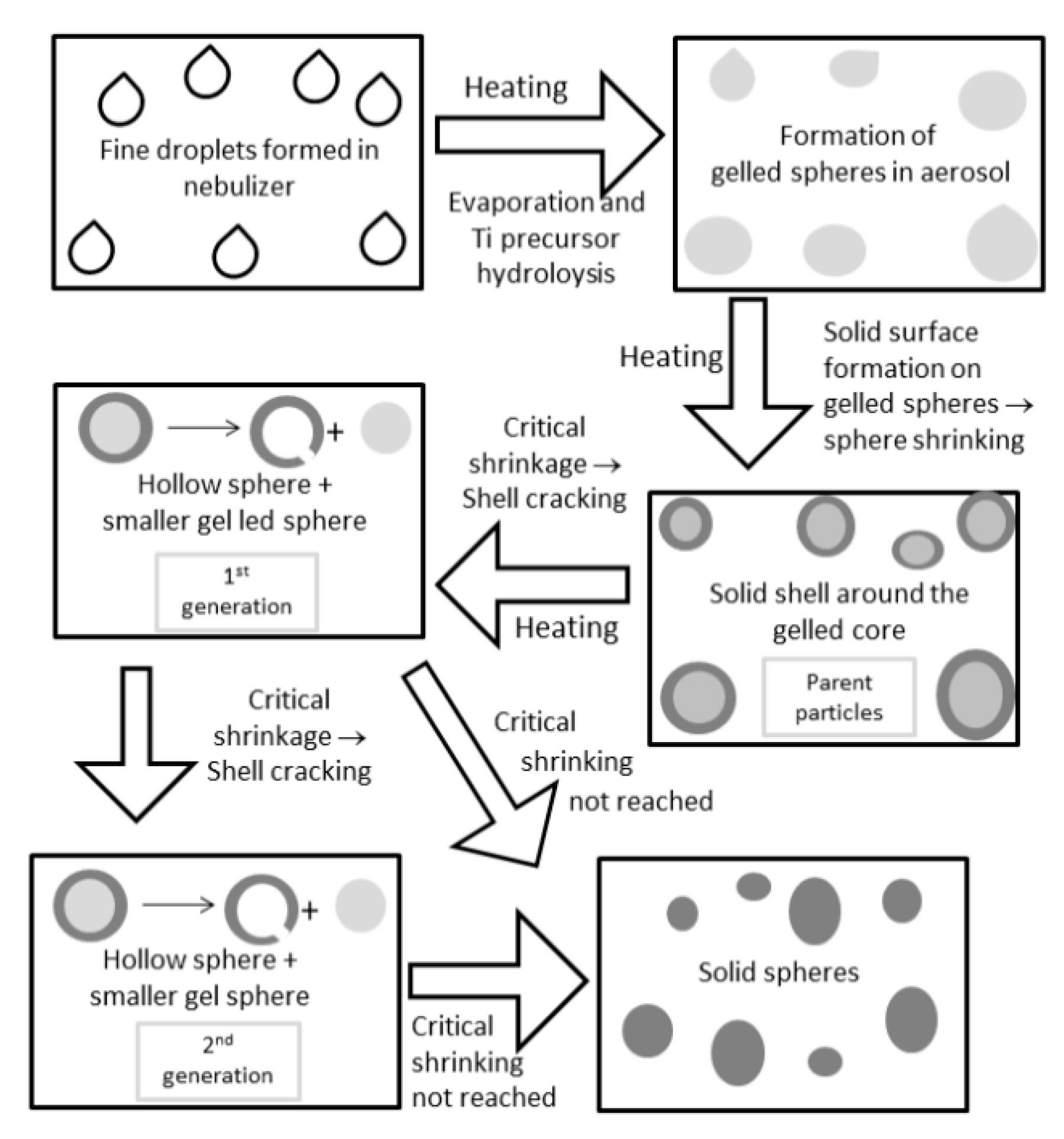
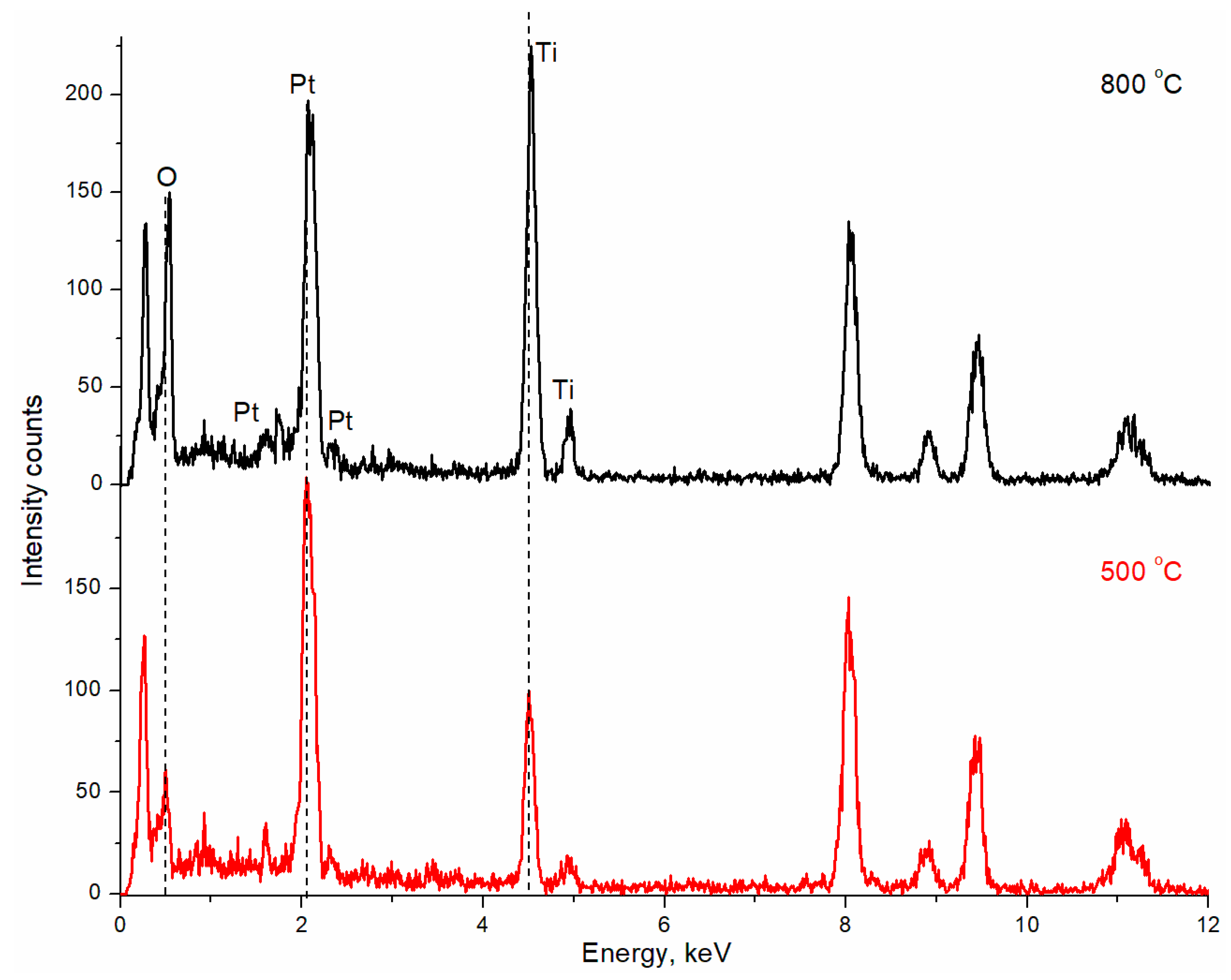
3.1. STEM and EDX Characterization of Pt/TiO2 Samples

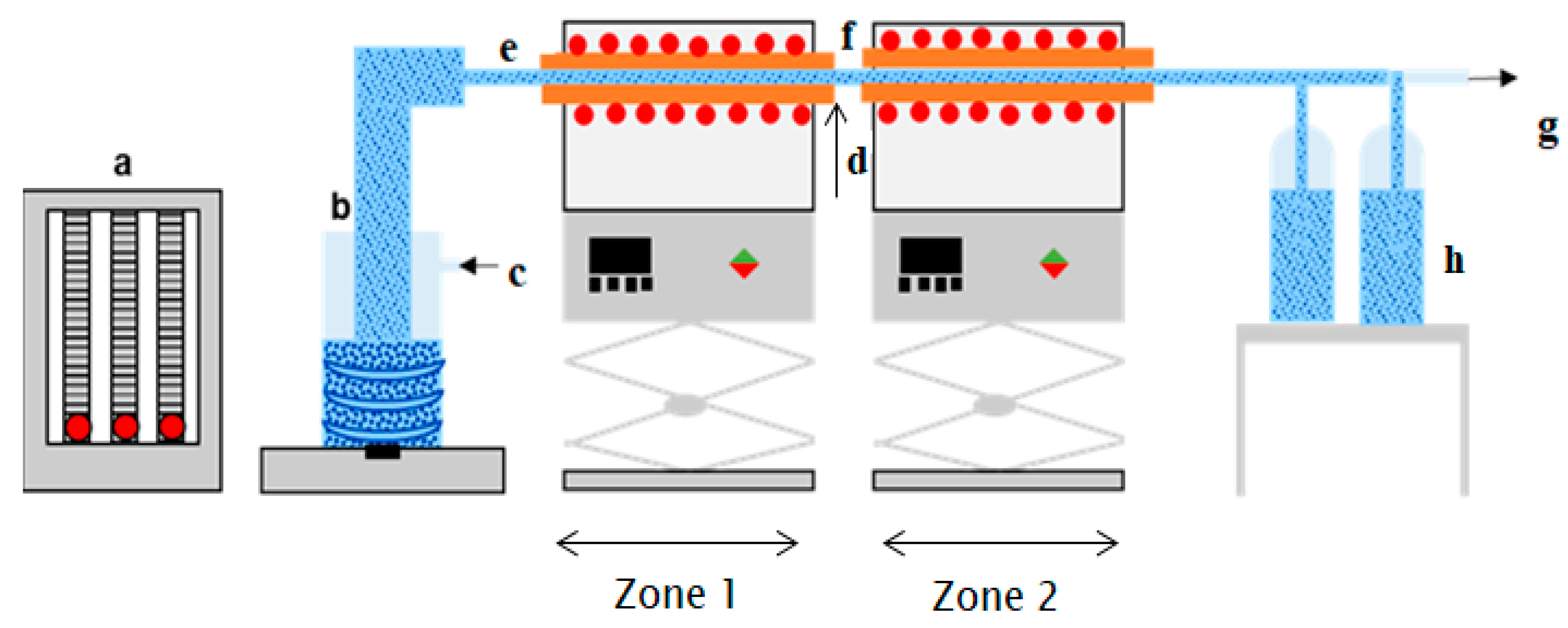
3.1.1. USP Pt/TiO2 Samples Synthesized In-Situ

A typical STEM annular dark field (ADF) image of the Pt/TiO2 composite particles from the in-situ synthesis with nominal 20 mass % Pt loading, synthesized at 800 °C, is shown in Figure 2a. The STEM image proves the regular spherical nature of the generated nanoparticles, which range between about 100 and 500 nm in size. The average particle diameter in this sample is 260 ± 80 nm. The typical geometrical motif in this sample is one larger particle, associated with a few smaller particles. Moreover, some of the larger particles are characterized by a circular darker zone in the particle center. Since the contrast in STEM ADF images at a particular position is governed by the atomic number and the sample thickness, the interpretation is straightforward and thus suggests the presence of hollow cores.
The assumption of hollow cores is also supported by local EDX measurements performed at the bright and dark areas (Table 1). The hollow particles have sizes of about 330 ± 90 nm and are thus larger than the average particles. Nevertheless, the results from the semiquantitative EDX in Table 1 show that the detected Pt loadings are lower than the expected nominal values (the detection uncertainty for Pt is about ± 3%). For 20% nominal Pt loading, it was 17.1 mass % (14.5% decrease), while for the 5% nominal Pt loading it was much smaller, i.e., 2.4 mass % (52% decrease). This indicates that the in-situ USP procedure requires additional optimization of the synthesis parameters, since mass and stoichiometric controls appear not to be ensured. Consequently, different types of Pt losses during the synthesis procedure can take place, causing lower Pt loading in synthesized materials. In addition, the EDX data reveal that the outer surface of the sphere contains slightly more Pt than at the inner surface of hollow sphere.
These findings allow us to propose the following mechanism for the USP generation of a Pt/TiO2 composite, as schematically presented in Figure 3. Fine droplets of aerosol are initially formed from the precursor solution in the nebulizer, which are subsequently transferred to the high-temperature zones of the USP furnace. If the droplets pass through a gel phase upon sudden heating, the solid shell around the gelled sphere could be formed during continued heating. It should be noted that it was observed that the precursor solution turns into sol after several weeks, which indicates the possibility of a sol-gel transition. Owing to thermal tensions during the solidification of a gel, it appears that the shell shrinks more rapidly than the gel is being solidified, which causes the shell to crack. The remaining highly tense gel phase flings off the shell, leaving a circular hole in the spherical wall, i.e., a new gelled sphere is delivered by its parent, which turned into a solid hollow sphere. If the shrinkage in a newly-born gelled sphere would prevail in the solidification of the interior, the delivering mechanism could be repeated.
The second-generation hollow spheres with holes of smaller diameter will then be formed, as seen in Figure 2a right beside the largest hollow sphere (first generation). The gelled sphere, being small enough, will turn solid throughout the volume without a breaking of the shell, which produces the solid spheres. These spheres are seen in Figure 2a with no holes on their surfaces, and they have sizes below the average (131 ± 42 nm). This mechanism can be visualized as the “opening of the Russian nesting doll”, which produces the particulate composition of the novel USP-synthesized Pt/TiO2 composite, colloquially defined as “Russian nesting doll”-like Pt/TiO2 spherical particles.
The separation of the initial gelled sphere into the parental hollow sphere and the newly-born smaller gelled sphere keeps the former with the Pt content distributed throughout the shell (Table 1). TiO2 tends to solidify faster than the Pt, thus causing every subsequent generation of the gelled, and afterwards solidified, sphere to be of lower Pt content with respect to its parental one. While the Pt content at the external shell side indicatively decreases, the relative decrease of Pt content for parental–newborn sphere pair (Table 1) also decreases. Here we consider the nominal loading as “parental” to that at the outer side of the first generation of the spheres (bright zone), while the latter plays the parent role for the loadings at the outer side of the second generation (the dark zone, Table 1). It follows that every next generation of the spheres in the mechanism of “the opening of the Russian nesting dolls” should get richer in Pt in the core of the gelled phase. Hence, the rest of Pt will be “trapped” within the core of the last generation of completely solidified sphere.
STEM images of spherical Pt/TiO2 particles of near-average diameters are shown in Figure 2b,c. Figure 2b illustrates the granular appearance of the Pt (20 mass %)/TiO2 sphere, with the surface populated by particles within the 3.4–7.8 nm size range, of an average diameter (±SD) of 5.2 ± 0.9 nm. However, the structure of the surface of the sphere walls depends on Pt content. The STEM appearances of an area of the two spheres of similar size, synthesized with nominal Pt loadings of 5 and 20 mass %, are compared in Figure 2c. The surface of the sphere with lower Pt loading (on the left in Figure 2c) appears smoother and more compact than the sphere with the higher Pt loading (on the right in Figure 2c). Higher Pt loading causes the sphere surface to show black spots-like particles that are 5.2 ± 0.9 nm in size. In order to identify the composition of the morphological elements at the sphere surface, EDX analysis has been performed, and the data related to area and point markers in Figure 2 are given in Table 2 and Table 3.
The surface composition of the smaller spheres was found to be higher (area 1 in Figure 2b) with respect to the biggest hollow sphere of the first generation (Figure 2a and Table 1). The sphere from Figure 2b is 194 nm in size, which is well below the average size—the criterion adopted for full solidification of the descendant gelled spheres in the mechanism of USP particle generation. Differently-shaded elements on the sphere surface were found to differ considerably in composition. The dark spots on a relatively uniform gray background (Figure 2c, sphere on the right) have considerably higher Pt content with respect to gray zones rich in TiO2 (Table 3, area right and left). Considerably different contents indicate that black spots could be Pt laying on the continuous spherical TiO2 matrix generated by the sol-gel transition of the oxide solid phase. Table 2 shows that 194-nm-sized sphere has 22.3 mass % Pt on the scanned area size of 1900 nm2, while on a sphere of 198 nm size, 15.2 mass % Pt was found on scanned area of 420 nm2. Since 5-nm-sized Pt particles lay on the TiO2 matrix, relative occupation of the scanned surface by Pt particles should increase with scanned surface area, which makes the EDX data on Pt content higher for a larger scanned area.
It follows from the preceding considerations about the mechanism of the in-situ USP generation of the Pt/TiO2 composite that, although being USP-intrinsic and intriguing, its structure and composition are not very promising for electrocatalytic applications. Despite that the average Pt loading in the synthesized spheres is fairly close to the nominal values (Table 1, Table 2 and Table 3), there is some deficiency of Pt at the surface of most of the bigger spheres. Moreover, residual Pt is likely distributed within smaller spheres, which prevents its addition to the catalytic activity of the composite. The reactants in aqueous medium easily approach the interior of the hollow sphere if the internal surface of the sphere wall contributes to the reaction. However, this should not be the case for hollow Pt/TiO2 spheres.

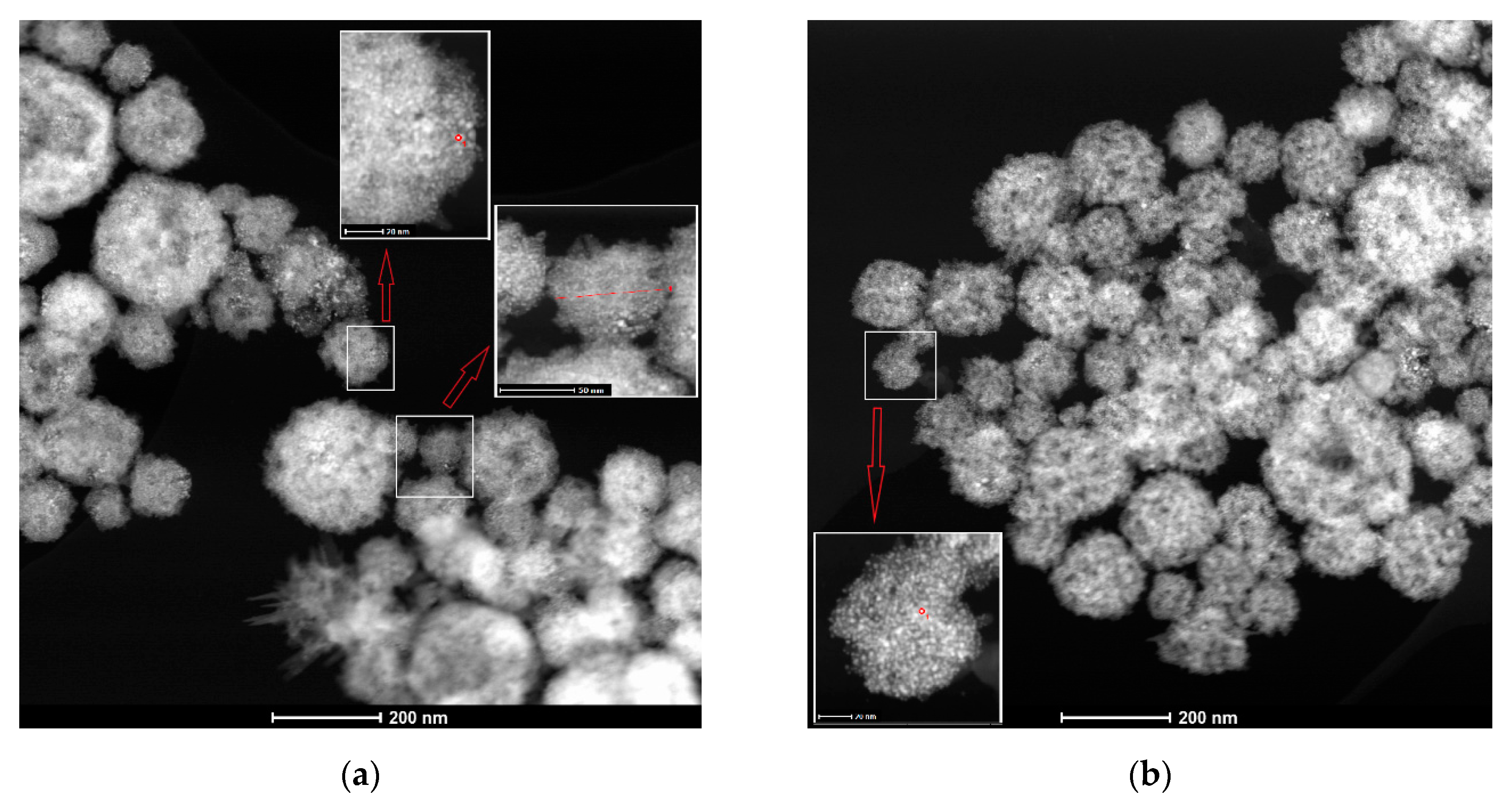
3.1.2. USP Pt/TiO2 Samples Synthesized Ex-Situ from Colloidal TiO2

Figure 4 shows STEM ADF images of Pt (20 mass %)/TiO2 synthesized by USP at 500 and 800 °C from previously hydrothermally-prepared colloidal TiO2 and chloroplatinic acid. The spheres appear smaller than those from the in-situ procedure, with average diameters (independent of USP temperature) of 137 ± 56 nm and 131 ± 42 nm at 500 and 800 °C, respectively. Although it is not obvious from Figure 4, the size distribution of the ex-situ spheres is more uniform (SD around 50 nm) with respect to in-situ spheres (SD around 80 nm). Statistical counting returned data showing extremely uniform size distribution of the particles: the surface of the 500 °C spheres are populated by particles with the sizes in the 1.1–1.3 nm range. Larger particles of the sizes in a wider range of 1.9–2.7 nm are formed at 800 °C. Besides the much smaller particles that are formed by the ex-situ approach, another crucial difference to the in-situ procedure is the looser and thus less compact structure of the spheres. This is expressed by their less well-defined outer contours.
Although the structure of the core of the spheres is not clear in Figure 4, in both point and line types of data collection, marked with red color in the inset of Figure 4a, EDX analysis showed the presence of Ti. Figure 5 shows the EDX spectra recorded at point 1 in both insets in Figure 4a,b. The corresponding Pt loadings are presented in Table 4.
In-point EDX spectra from Figure 5 show clear reflections of Ti, O, and Pt for samples synthesized ex-situ at 500 and 800 °C. Peaks over 8 eV come from Cu (the substrate used for EDX measurements) and Pt. The intensities of Ti and O reflections are suppressed for the 500 °C sample relatively to the 800 °C sample, while the intensities of main Pt peaks are almost the same. Although the coordinates of the EDX sampling points with respect to the sphere center differ (in the case of the inset in Figure 4a, it is closer to the edge of sphere), the suppressing might indicate that reflections related to TiO2 come from internal parts of the sphere. On the other hand, the similarity of the Pt peak intensities suggests that Pt is placed on the sphere surface in almost pure form, and it is formed of nm-sized spherical particles, as seen in Figure 4. These considerations appear to be reasonable, since the Pt loadings in the 500 °C and the 800 °C samples are similar, with that in the former being slightly larger. Another indication about ordered positions of the two components is found in the in-line EDX analysis, as shown in the inset in Figure 4a. The average Pt loading down the line across the sphere is considerably lower than in-point loading. Since TiO2 is located in the core, the surface EDX analysis should register the increase in Pt loading at the line ends (sphere edges) with respect to central sphere zones. The size and shape of hydrothermally-prepared TiO2 particles in colloidal dispersion were found to be quite similar [36] to the spheres from Figure 4. For all samples synthesized ex-situ, the EDX analysis found considerable excess of Pt with respect to the nominal loading. Hence, the hierarchical ordering of the Pt nm-sized particles which coat the TiO2 spherical core is reached. Also, the size of particles obtained by both methods, in-situ and ex-situ synthesis, was below 10 nm, which is the optimal size for the improved electrocatalytical activity of Pt as reported in literature [31,32].

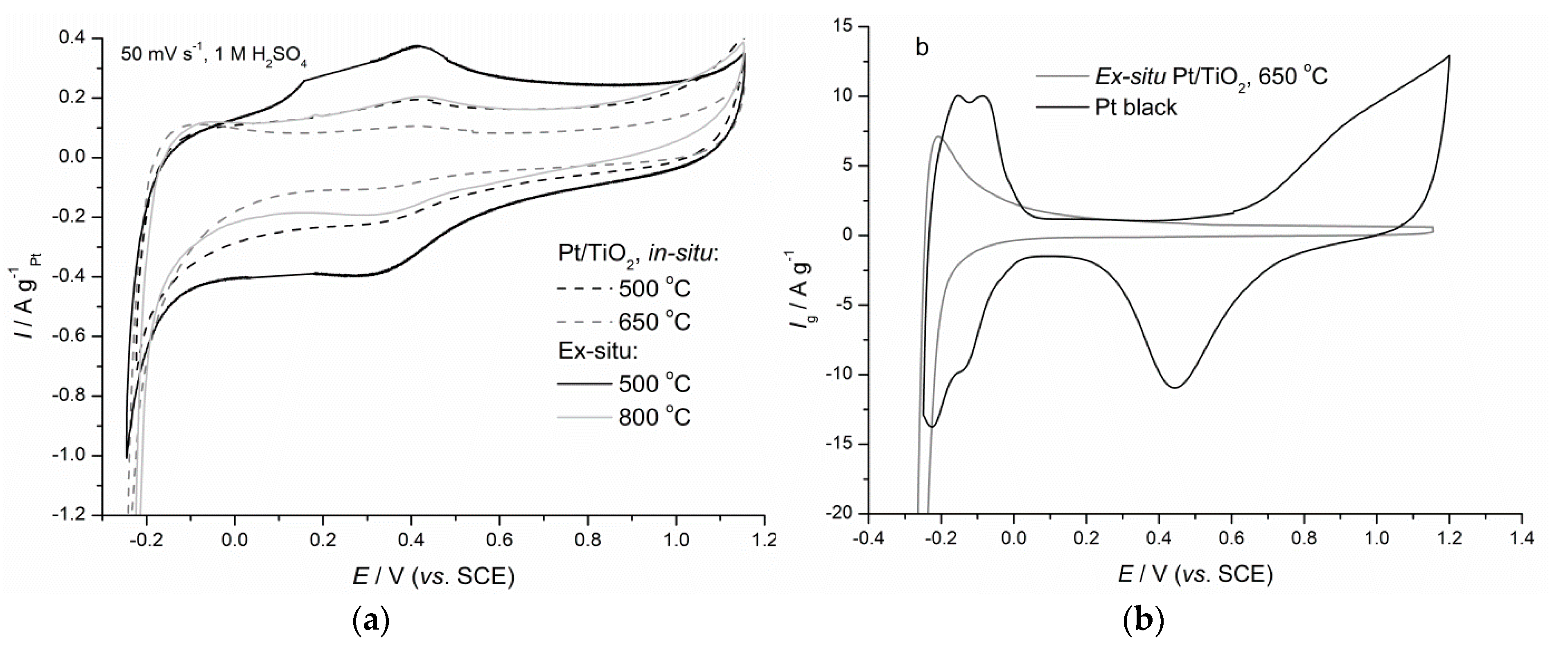
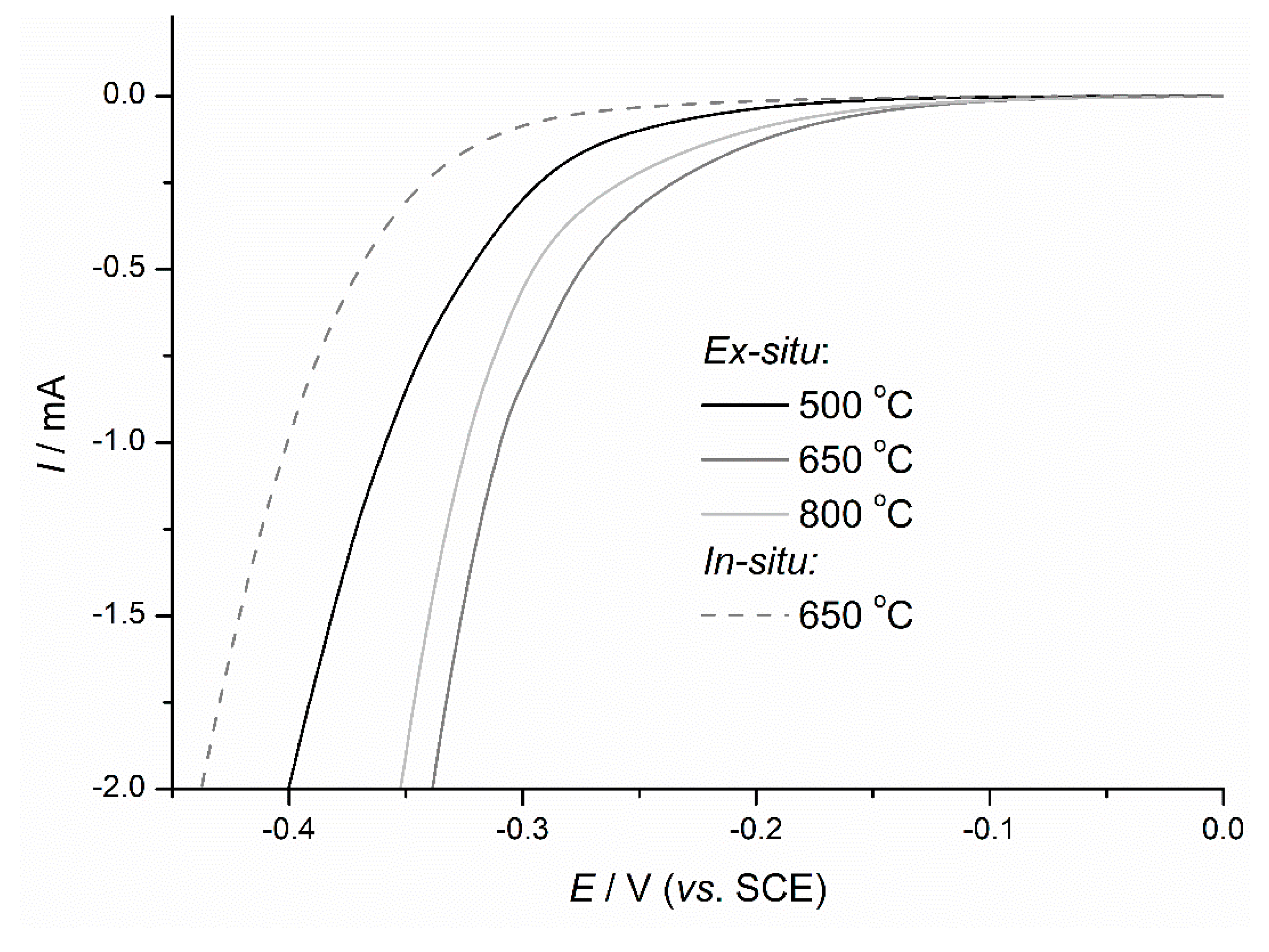
3.2. Electrochemical Measurements

Characteristic steady-state cyclic voltammograms of synthesized Pt/TiO2, compared with those obtained for commercial Pt black (Johnson Matthey), are shown in Figure 6. The samples synthesized in-situ with nominal Pt loading of 5 mass % were not considered, since the loading is too low for measuring electrochemical characteristics.
All registered CVs of USP synthesized Pt/TiO2 are almost featureless in the potential region above 0 V, without clearly developed Pt oxide formation and reduction, as in the case of Pt black.
With the exception of the sample synthesized ex-situ at 650 °C (Figure 6b), values of CV currents of all the other Pt/TiO2 samples are below 5 µA. Additionally, hydrogen reduction/oxidation peaks of considerable currents [52] at around –0.2 V are clearly registered only for the 650 °C sample with 20 mass % Pt. None of the samples show hydrogen adsorption/desorption region typical for Pt, as seen for Pt black (Figure 6b). Compared to the literature data on a 40 mass % Pt/TiO2 electrocatalyst [53], the value of hydrogen reduction/oxidation currents obtained for this 650 °C is not significantly larger, i.e., 7 A·g−1 in comparison with 1.25 A·g−1, although the Pt loading is twice larger.
The electrochemical properties of the ex-situ synthesized Pt/TiO2 show considerable dependence on USP temperature. It appears that the suitable hierarchical structure is achieved at 650 °C, with electrochemically advantageous Pt size and distribution over the TiO2 core, along the trend discussed in relation to the STEM images from Figure 4.
Although a full CV fingerprint of Pt was not registered for the synthesized Pt/TiO2 composites, the samples show electrochemical activity for an oxygen reduction reaction and combined oxygen reduction and hydrogen evolution reactions. Initial quasi-steady-state polarization curves for competing oxygen reduction (OR)/hydrogen evolution (HE) at low and moderate currents are shown in Figure 7.
As already observed in CV responses (Figure 6), where the highest currents in HE region were registered for the 650 °C sample, this sample shows best polarization characteristics, as seen in Figure 7. In general, the ex-situ synthesized samples have considerably higher OR/HE activity compared to the activity of samples synthesized in-situ. The differences in activity are to be assigned to different component distributions and surface compositions of the spheres as constituents of in-situ and ex-situ synthesized Pt/TiO2. Pt loading at the surface of ex-situ synthesized spheres is higher and exceeds nominal loading, since small Pt particles decorate uniformly and cover regularly the surface of TiO2 spherical core. Pt particles are smaller than those prepared in-situ. This hierarchy is beneficial for full availability of high-surface-area Pt for the OR/HE process. The in-situ prepared Pt/TiO2 has lower surface Pt loading, with most of the active components constituting the walls of huge hollow spheres or the inactive cores of smaller spheres. These morphological elements have randomly mixed components and larger Pt particles which are hardly accessible as reaction sites (those facing the interior of the hollow spheres or being buried inside the solid spheres). Hence, the differences seen in Figure 6a,b are due to larger number of active sites readily accessible for the reaction in the case of the ex-situ synthesized Pt/TiO2 composite.
Tafel representations of quasi-steady-state polarization curves for the Pt/TiO2 composites from Figure 7 are shown in Figure 8.
In the low overpotential region, 0.6–0.0 V, all Pt/TiO2 composites show poor activity, exhibiting high values of the slopes. At 0 V, these values shifted to around 120 mV·dec−1, characteristic for the ORR, but also for HER at high overpotential [54,55,56]. If compared to Pt polarization, the ORR on Pt/TiO2 has high initial overpotential, and hence, has considerably shifted cathodically. The curves take the slope close to −120 mV/dec around 0.0 V vs. SCE, while the curve for Pt black reaches the ORR limiting current already at ca. 0.4 V. Since the potential of 0.0 V is positive to the thermodynamic onset of HER (−0.243 V vs. SCE), it follows that Pt/TiO2 shows measurable ORR activity at the potentials as negative at 0.0 V. At the potentials negative to −0.2 V, the thermodynamic condition for the onset of HER is fulfilled and polarization curves for Pt/TiO2 represent joint ORR/HER activity. No changes in the slope upon the HER onset are detected, which indicates that both ORR and HER could proceed on Pt/TiO2 with high surface coverage and surface recombination/desorption as the rate-determining steps. Since Pt oxide formation/reduction is suppressed on Pt/TiO2 (Figure 6b), the polarization data indicate that Pt states in mixture with or on a TiO2 surface have poor activity towards the adsorption of oxygen-containing species and moieties, due to Pt interaction with TiO2 [48]. However, the interaction appears to stabilize the adsorbed hydrogen, causing the high surface coverage. As indicated in Figure 7, and seen also in Figure 8, ex-situ synthesized Pt/TiO2 samples are considerably more active for ORR/HER than in-situ synthesized samples.

4. Conclusions

Spherical Pt/TiO2 composite materials of novel structure and characteristic component distribution were synthesized at different temperatures using ultrasonic spray pyrolysis (USP). In the ex-situ synthesis, TiO2 colloid and chloroplatinic acid were used as precursors, while the in-situ approach was based on tetra-n-butyl orthotitanate and chloroplatinic acid in an hydrochloric acid solution as precursors. While in-situ USP synthesis generates the mixture of huge hollow spheres and 100-nm-sized solid spheres with deficient Pt loading due to intrinsic aerosol-gel/solid phase transition, the regular TiO2 spherical cores, with the surface uniformly covered by the shell of nm-sized Pt particles, are synthesized via the ex-situ approach. Accordingly, the ex-situ synthesized samples are more active for electrochemical oxygen reduction and combined oxygen reduction and hydrogen evolution reactions than the in-situ samples. The prepared samples were electrochemically checked using cyclic (CV) and linear sweep voltammetry (LSV) and collected responses were compared to those obtained for Pt black. The benefit of the USP prepared samples compared to Pt black is considerably increased CV cathodic currents in the hydrogen reduction region. The highest CV currents were registered for the ex-situ sample synthesized at 650 °C as a moderate USP temperature, with nominal 20 mass % Pt. This sample also showed the highest activity for oxygen reduction/combined oxygen reduction and hydrogen evolution reactions. Higher affinity of Pt in Pt/TiO2 toward hydrogen than for the adsorption of oxygen-containing species is clear.

Author Contributions

Conceptualization, J.S.S. and B.G.F.; methodology, V.V.P. and S.R.S.; formal analysis, T.E.W.; investigation, M.G.K. and M.M.Z.; data curation, M.G.K.; writing—original draft preparation, M.G.K. and M.M.Z.; writing—review and editing, V.V.P. and T.E.W.; supervision, V.V.P., B.G.F. and J.S.S.; project administration, V.V.P. and S.R.S. All authors have read and agreed to the published version of the manuscript.

Funding

This research was funded by Ministry of Education, Science and Technological Development of the Republic of Serbia, grant number 172060 and by the funds of the bilateral research project, ID 451-03-01413/2016-09/7, supported by DAAD, Germany.

Acknowledgments

This work was supported by the Ministry of Education, Science and Technological Development of the Republic of Serbia (Grant No. 172060). We would like to thank the German Academic Exchange Service DAAD for the financial support at the project No. 57334757 under title “Novel designs of synthesis for tailoring the ordered structures of multicomponent metal oxides as uniform coatings of activated titanium anodes” between 01.01.2017 to 31.12.2018. Especially, the authors would like to thank Cleopatra Herwartz, GFE Central Facility for Electron Microscopy, RWTH Aachen University for recording STEM images and EDS spectra of the samples.

Conflicts of Interest

The authors declare no conflict of interest.

References

  1. Berber, M.R.; Hafez, I.H.; Fujigaya, T.; Nakashima, N. A highly durable fuel cell electrocatalyst based on double-polymer-coated carbon nanotubes. Sci. Rep. 2015, 5, 16711. [Google Scholar] [CrossRef]
  2. Wang, J. System integration, durability and reliability of fuel cells: Challenges and solutions. Appl. Energy 2017, 189, 460–479. [Google Scholar] [CrossRef]
  3. Bae, S.J.; Kim, S.-J.; Lee, J.-H.; Song, I.; Kim, N.-I.; Seo, Y.; Kim, K.B.; Lee, N.; Park, J.-Y. Degradation pattern prediction of a polymer electrolyte membrane fuel cell stack with series reliability structure via durability data of single cells. Appl. Energy 2014, 131, 48–55. [Google Scholar] [CrossRef]
  4. Wang, X.X.; Tan, Z.H.; Zeng, M.; Wang, J.N. Carbon nanocages: A new support material for Pt catalyst with remarkably high durability. Sci. Rep. 2014, 4, 1–11. [Google Scholar] [CrossRef] [PubMed] [Green Version]
  5. Sharma, R.; Gyergyek, S.; Li, Q.; Andersen, S.M. Evolution of the degradation mechanisms with the number of stress cycles during an accelerated stress test of carbon supported platinum nanoparticles. J. Electroanal. Chem. 2019, 838, 82–88. [Google Scholar] [CrossRef]
  6. Teran-Salgado, E.; Bahena-Uribe, D.; Márquez-Aguilar, P.A.; Reyes-Rodriguez, J.L.; Cruz-Silva, R.; Solorza-Feria, O. Platinum nanoparticles supported on electrochemically oxidized and exfoliated graphite for the oxygen reduction reaction. Electrochim. Acta 2019, 298, 172–185. [Google Scholar] [CrossRef]
  7. Kim, Y.; Lee, D.; Kwon, Y.; Kim, T.-W.; Kim, K.; Kim, H.J. Enhanced electrochemical oxygen reduction reaction performance with Pt nanocluster catalysts supported on microporous graphene-like 3D carbon. J. Electroanal. Chem. 2019, 838, 89–93. [Google Scholar] [CrossRef]
  8. Teng, X.; Yang, H. Synthesis and electrocatalytic property of cubic and spherical nanoparticles of cobalt platinum alloys. Front. Chem. Eng. China 2010, 4, 45–51. [Google Scholar] [CrossRef]
  9. Krstajić Pajić, M.N.; Stevanović, S.I.; Radmilović, V.V.; Gavrilović-Wohlmutherc, A.; Radmilović, V.R.; Gojković, S.L.; Jovanović, V.M. Shape evolution of carbon supported Pt nanopar-ticles: From synthesis to application. Appl. Catal. B Environ. 2016, 196, 174–184. [Google Scholar] [CrossRef]
  10. Mourdikoudis, S.; Chirea, M.; Altantzis, T.; Pastoriza-Santos, I.; Pe’rez-Juste, J.; Silva, F.; Bals, S.; Liz-Marzan, L.M. Dimethylformamide-mediated synthesis of water-soluble platinum nanodendrites for ethanol oxidation electrocatalysis†. Nanoscale 2013, 5, 4776–4784. [Google Scholar] [CrossRef]
  11. Gao, Q.; Gao, M.R.; Liu, J.W.; Chen, M.Y.; Cui, C.H.; Lia, H.H.; Yu, S.H. One-pot synthesis of branched palladium nanodendrites with superior electrocatalytic performance. Nanoscale 2013, 5, 3202–3207. [Google Scholar] [CrossRef] [PubMed]
  12. Sui, S.; Wang, X.; Zhou, X.; Su, Y.; Riffat, S.; Liu, C.-J. A comprehensive review of Pt electrocatalysts for the oxygen reduction reaction: Nanostructure, activity, mechanism and carbon support in PEM fuel cells. J. Mater. Chem. A 2017, 5, 1808–1825. [Google Scholar] [CrossRef]
  13. Wang, R.; Wang, H.; Luo, F.; Liao, S. Core–Shell-Structured Low-Platinum Electrocatalysts for Fuel Cell Applications. Electrochem. Energy Rev. 2018, 1, 324–387. [Google Scholar] [CrossRef]
  14. Jayawickrama, S.M.; Han, Z.; Kido, S.; Nakashima, N.; Fujigaya, T. Enhanced platinum utilization efficiency of polymer-coated carbon black as an electrocatalyst in polymer electrolyte membrane fuel cells. Electrochim. Acta 2019, 312, 349–357. [Google Scholar] [CrossRef]
  15. Devrim, Y.; Arıca, E.D. Multi-walled carbon nanotubes decorated by platinum catalyst for high temperature PEM fuel cell. Int. J. Hydrog. Energy 2019, 44, 18951–18966. [Google Scholar] [CrossRef]
  16. Berghian-Grosan, C.; Radu, T.; Biris, A.R.; Dan, M.; Voica, C.; Watanabe, F.; Biris, A.S.; Vulcu, A. Platinum nanoparticles coated by graphene layers: A low-metal loading catalyst for methanol oxidation in alkaline media. J. Energy Chem. 2020, 40, 81–88. [Google Scholar] [CrossRef] [Green Version]
  17. Alcaide, F.; Álvarez, G.; Miguel, O.; Lázaro, M.J.; Moliner, R.; López-Cudero, A.; Solla-Gullón, J.; Herrero, E.; Aldaz, A. Pt supported on carbon nanofibers as electrocatalyst for low temperature polymer electrolyte membrane fuel cells. Electrochem. Commun. 2009, 11, 1081–1084. [Google Scholar] [CrossRef]
  18. Fraser, A.; Zhang, Z.; Merle, G.; Gbureck, U.; Ye, S.; Gostick, J.; Barralet, J. Composite Carbon Nanotube Microsphere Coatings for Use as Electrode Supports. Adv. Funct. Mater. 2018, 28, 1803713. [Google Scholar] [CrossRef]
  19. Lafforgue, C.; Zadick, A.; Dubau, L.; Maillard, F.; Chatenet, M. Selected Review of the Degradation of Pt and Pd-based Carbon-supported Electrocatalysts for Alkaline Fuel Cells: Towards Mechanisms of Degradation. Fuel Cells 2018, 18, 229–238. [Google Scholar] [CrossRef]
  20. Kreitmeier, S.; Wokaun, A.; Büchi, F.N. Local Catalyst Support Degradation during Polymer Electrolyte Fuel Cell Start-Up and Shutdown. J. Electrochem. Soc. 2012, 159, F787–F793. [Google Scholar] [CrossRef]
  21. Zhang, Y.; Chen, S.; Wang, Y.; Ding, W.; Wu, R.; Li, L.; Qi, X.; Wei, Z. Study of the degradation mechanisms of carbon-supported platinum fuel cells catalyst via different accelerated stress test. J. Power Sources 2015, 273, 62–69. [Google Scholar] [CrossRef]
  22. Wu, Z.; Dang, D.; Tian, X. Designing Robust Support for Pt Alloy Nanoframes with Durable Oxygen Reduction Reaction Activity. ACS Appl. Mater. Interfaces 2019, 11, 9117–9124. [Google Scholar] [CrossRef] [PubMed]
  23. Liu, F.; Wu, Z.; Dang, D.; Wang, G.; Tian, X.; Yang, X. Three dimensional titanium molybdenum nitride nanowire assemblies as highly efficient and durable platinum support for methanol oxidation reaction. Electrochim. Acta 2019, 295, 50–57. [Google Scholar] [CrossRef]
  24. Huynh, T.T.; Pham, H.Q.; Nguyen, A.V.; Bach, L.G.; Ho, V.T.T. Advanced Nanoelectrocatalyst of Pt Nanoparticles Supported on Robust Ti0.7Ir0.3O2 as a Promising Catalyst for Fuel Cells. Ind. Eng. Chem. Res. 2019, 58, 675–684. [Google Scholar] [CrossRef]
  25. Liu, F.; Dang, D.; Tian, X. Platinum-decorated three dimensional titanium copper nitride architectures with durable methanol oxidation reaction activity. J. Hydrog. Energy 2019, 44, 8415–8424. [Google Scholar] [CrossRef]
  26. Kim, S.-W.; Han, T.H.; Kim, J.; Gwon, H.; Moon, H.-S.; Kang, S.-W.; Kim, S.O.; Kang, K. Fabrication and Electrochemical Characterization of TiO2 Three-Dimensional Nanonetwork Based on Peptide Assembly. ACS Nano 2009, 3, 1085–1090. [Google Scholar] [CrossRef]
  27. Diebold, U. The surface science of titanium dioxide. Surf. Sci. Rep. 2003, 48, 53–229. [Google Scholar] [CrossRef]
  28. Fovet, Y.; Gal, J.Y.; Toumelin-Chemla, F. Influence of pH and fluoride concentration on titanium passivating layer: Stability of titanium dioxide. Talanta 2001, 53, 1053–1063. [Google Scholar] [CrossRef]
  29. Lewera, A.; Timperman, L.; Roguska, A.; Alonso-Vante, N. Metal-support interactions between nanosized Pt and metal oxides (WO3 and TiO2) studied using X-ray photoelectron spectroscopy. J. Phys. Chem. C 2011, 115, 20153–20159. [Google Scholar] [CrossRef]
  30. Dulub, O.; Hebenstreit, W.; Diebold, U. Imaging cluster surfaces with atomic resolution: The strong metal-support interaction state of Pt supported on TiO2 (110). Phys. Rev. Lett. 2000, 84, 3646–3649. [Google Scholar] [CrossRef] [Green Version]
  31. Kim, D.-S.; Zeid, A.; Kim, Y.-T. Additive treatment effect of TiO2 as supports for Pt-based electrocatalysts on oxygen reduction reaction activity. Electrochim. Acta 2010, 55, 3628–3633. [Google Scholar] [CrossRef]
  32. Wang, Y.; Mohamedi, M. Hierarchically organized nanostructured TiO2/Pt on microfibrous carbon paper substrate for ethanol fuel cell reaction. Int. J. Hydrog. Energy 2017, 42, 22796–22804. [Google Scholar] [CrossRef]
  33. Amer, M.S.; Ghanem, M.A.; Al-Mayouf, A.M.; Prabhakarn, A.N.H. Low-loading of oxidized platinum nanoparticles into mesoporous titanium dioxide for effective and durable hydrogen evolution in acidic media. Arab. J. Chem. 2018. [Google Scholar] [CrossRef]
  34. Shaddad, M.N.; Al-Mayouf, A.M.; Ghanem, M.A.; AlHoshan, M.S.; Singh, J.P.; Al-Suhybani, A.A. Chemical Deposition and Electrocatalytic Activity of Platinum Nanoparticles Supported on TiO2 Nanotubes. Int. J. Electrochem. Sci. 2013, 8, 2468–2478. [Google Scholar]
  35. Guo, P.; Xu, W.; Zhu, S.; Yang, X.; Inoue, A. Preparation and electrocatalytic performance of the Pt supported on the alkali-treated nanoporous TiO2 material. Ionics 2015, 21, 2863–2869. [Google Scholar] [CrossRef]
  36. Košević, M.; Šekularac, G.; Živković, L.; Panić, V.; Nikolić, B. TiO2 From Colloidal Dispersion as Support in Pt/TiO2 Nanocomposite for Electrochemical Applications. Croat. Chem. Acta 2017, 90, 251–258. [Google Scholar] [CrossRef]
  37. Fugare, B.Y.; Lokhande, B.J. Study on structural, morphological, electrochemical and corrosion properties of mesoporous RuO2 thin films prepared by ultrasonic spray pyrolysis for supercapacitor electrode application. Mater. Sci. Semicond. Process. 2017, 71, 121–127. [Google Scholar] [CrossRef]
  38. Muñoz-Fernandez, L.; Alkan, G.; Milošević, O.; Rabanal, M.E.; Friedrich, B. Synthesis and characterisation of spherical core-shell Ag/ZnO nanocomposites using single and two—Steps ultrasonic spray pyrolysis (USP). Catal. Today 2019, 321–322, 26–33. [Google Scholar] [CrossRef] [Green Version]
  39. Alkan, G.; Diaz, F.; Matula, G.; Stopic, S.; Friedrich, B. Scaling up of nanopowder collection in the process of ultrasonic spray pyrolysis. World Metall.-ERZMETALL 2017, 70, 97–101. [Google Scholar]
  40. Mata, V.; Maldonado, A.; Olvera, M.L. Deposition of ZnO thin films by ultrasonic spray pyrolysis technique. Effect of the milling speed and time and its application in photocatalysis. Mater. Sci. Semicond. Process. 2018, 75, 288–295. [Google Scholar] [CrossRef]
  41. Liang, F.; Chen, S.; Xie, W.; Zou, C. The decoration of Nb-doped TiO2 microspheres by reduced graphene oxide for enhanced CO gas sensing. J. Phys. Chem. Solids 2018, 114, 195–200. [Google Scholar] [CrossRef]
  42. Alkan, G.; Rudolf, R.; Bogovic, J.; Jenko, D.; Friedrich, B. Structure and Formation Model of Ag/TiO2 and Au/TiO2 Nanoparticles Synthesized through Ultrasonic Spray Pyrolysis. Metals 2017, 7, 389. [Google Scholar] [CrossRef] [Green Version]
  43. Zhang, J.; Mo, Y.; Vukmirovic, M.B.; Klie, R.; Sasaki, K.; Adzic, R.R. Platinum Monolayer Electrocatalysts for O2 Reduction:  Pt Monolayer on Pd(111) and on Carbon-Supported Pd Nanoparticles. J. Phys. Chem. B 2004, 108, 10955–10964. [Google Scholar] [CrossRef]
  44. Esmaeilifar, A.; Rowshanzamir, S.; Eikani, M.H.; Ghazanfari, E. Synthesis methods of low-Pt-loading electrocatalysts for proton exchange membrane fuel cell systems. Energy 2010, 35, 3941–3957. [Google Scholar] [CrossRef]
  45. Arici, E.; Kaplan, B.Y.; Mert, A.M.; Gursel, S.A.; Kinayyigit, S. An effective electrocatalyst based on platinum nanoparticles supported with graphene nanoplatelets and carbon black hybrid for PEM fuel cell. Int. J. Hydrog. Energy 2019, 44, 14175–14183. [Google Scholar] [CrossRef]
  46. Yang, Z.; Chen, M.; Xia, M.; Wang, M.; Wang, X. An effective and durable interface structure design for oxygen reduction and methanol oxidation electrocatalyst. Appl. Surf. Sci. 2019, 487, 655–663. [Google Scholar] [CrossRef]
  47. Huang, W.; Wang, H.; Zhou, J.; Wang, J.; Duchesne, P.N.; Muir, D.; Zhang, P.; Han, N.; Zhao, F.; Zeng, M.; et al. Highly active and durable methanol oxidation electrocatalyst based on the synergy of platinum–nickel hydroxide–graphene. Nat. Commun. 2015, 6, 1–8. [Google Scholar] [CrossRef]
  48. Jakšić, M.M. Advances in electrocatalysis for hydrogen evolution in the light of the Brewer-Engel valence-bond theory. J. Mol. Catal. 1986, 38, 161–202. [Google Scholar] [CrossRef]
  49. Zheng, H.; Wang, C.; Zhang, X.; Li, Y.; Ma, H.; Liu, Y. Control over energy level match in Keggin polyoxometallate-TiO2 microspheres for multielectron photocatalytic reactions. Appl. Catal. B 2018, 234, 79–89. [Google Scholar] [CrossRef]
  50. Yang, J.; Wang, G.; Wang, D.; Liu, C.; Zhang, Z. A self-cleaning coating material of TiO2 porous microspheres/cement composite with high-efficient photocatalytic depollution performance. Mater. Lett. 2017, 200, 1–5. [Google Scholar] [CrossRef]
  51. Stopic, S.; Friedrich, B.; Schroeder, M.; Weirich, T.E. Synthesis of TiO2 core/RuO2 shell particles using multistep ultrasonic spray pyrolysis. Mater. Res. Bull. 2013, 48, 3633–3635. [Google Scholar] [CrossRef]
  52. Kundu, M.K.; Bhowmik, T.; Mishra, R.; Barman, S. Pt Nanostructures/N-Doped Carbon hybrid, an Efficient Catalyst for Hydrogen Evolution/Oxidation Reactions: Enhancing its Base Media Activity through Bi-functionality of the Catalyst. ChemSusChem 2018, 11, 2388–2401. [Google Scholar] [CrossRef] [PubMed]
  53. Dhanasekaran, P.; Vinod Selvaganesh, S.; Sarathi, L.; Santoshkumar, D.B. Rutile TiO2 Supported Pt as Stable Electrocatalyst for Improved Oxygen Reduction Reaction and Durability in Polymer Electrolyte Fuel Cell. Electrocatalysis 2016, 7, 495–506. [Google Scholar] [CrossRef]
  54. Chiwata, M.; Kakinuma, K.; Wakisaka, M.; Uchida, M.; Deki, S.; Watanabe, M.; Uchida, H. Oxygen Reduction Reaction Activity and Durability of Pt Catalysts Supported on Titanium Carbide. Catalysts 2015, 5, 966–980. [Google Scholar] [CrossRef] [Green Version]
  55. Antoine, O.; Bultel, Y.; Durand, R. Oxygen reduction reaction kinetics and mechanism on platinum nanoparticles inside Nafion®. J. Electroanal. Chem 2001, 499, 85–94. [Google Scholar] [CrossRef]
  56. Creţu, R.; Kellenberger, A.; Vaszilcsin, N. Enhancement of hydrogen evolution reaction on platinum cathode by proton carriers. Int. J. Hydrog. Energy 2013, 38, 11685–11694. [Google Scholar] [CrossRef]
Figure 1. Experimental set-up used for ultrasonic spray syntheses (a) gas flow regulation of N2 and H2, (b) ultrasonic generator with precursor solution (c) gas inlet 1, N2 (d) gas inlet 2, H2, (e) furnace 1, (f) furnace 2, (g) gas outlet and (h) collection bottles
Metals 10 00011 g001
Figure 2. (a) Typical annular dark field (ADF) scanning transmission electron microscopy (STEM) image of an agglomerate of the Pt/TiO2 composite particles that have been synthesized by in-situ ultrasonic spray pyrolysis (USP). Image contrast and EDX (energy dispersive spectroscopy) analysis at the indicated numbered positions prove that a part of the particles has a core-shell structure with hollow core. (b) The ADF STEM shows a typical spherical in-situ Pt/TiO2 particle (at 650°C) at larger magnification. It should be noted that the speckled appearance of the particle indicates that the nanoparticle itself is composed of a large number of nanosized crystallites. (c) The STEM bright-field image shows part of two adjacent spherical particles with nominal 5 mass % (left) and 20 mass % (right) Pt loadings (the boxed areas mark the positions that have been analyzed by EDX spectroscopy).
Metals 10 00011 g002
Figure 3. Schematic illustration of the in-situ USP mechanism for the formation of hollow and solid spheres of TiO2/Pt.
Metals 10 00011 g003
Figure 4. STEM ADF images of ex-situ Pt/TiO2 composites obtained from the mixture of TiO2 colloid and H2PtCl6 solution with projected mass of 20% Pt/TiO2 at (a) 500 °C and (b) 800 °C.
Metals 10 00011 g004
Figure 5. EDX Spectra of USP ex-situ prepared Pt/TiO2 at 800 °C and 500 °C.
Metals 10 00011 g005
Figure 6. Comparison of cyclic voltammograms of Pt/TiO2 composites and Pt black (a) and ex-situ at 650 °C (b) in de-aerated 1.0 M H2SO4, sweep rate 50 mV·s−1.
Metals 10 00011 g006
Figure 7. Initial quasi-steady-state polarization curves for combined oxygen reduction and hydrogen evolution reactions at low and moderate currents of Pt/TiO2 composites. Electrolyte: O2 purged 1 M H2SO4; 1 mV·s−1.
Metals 10 00011 g007
Figure 8. Tafel representation of quasi-steady-state polarization curves for oxygen reduction reaction (ORR) (above -0.2 V) and combined ORR/hydrogen evolution reaction (HER) (below −0.2 V) of Pt/TiO2 composites compared to Pt black. Electrolyte: O2-purged 1 M H2SO4; 1 mV⋅s−1.
Metals 10 00011 g008
Table 1. Pt loadings (mass %) in the particle walls found by semiquantitative EDX analysis for the in-situ synthesized Pt/TiO2 particles and the relative decrease with respect to nominal (20 mass % Pt) or Pt loading at the outer side of parental sphere. The composition at the inner side is considered as that of the outer side of a newly-born sphere.
ZoneNominal Pt Loading, Mass %Found Pt Loading Mass %RelativeDecrease, %
Bright (outer side of the sphere wall, Figure 2a, area 2)2017.114.5
Dark (inner side of the sphere wall, Figure 2a, area 1)15.49.94
Table 2. Pt loadings (mass%) on the outer side of particle walls found by EDX analysis for the in-situ synthesized Pt/TiO2 particles with nominal Pt loadings of 5 and 20 mass %. EDX sampling was performed according to the markers given in Figure 2b,c.
EDX SamplingNominal Pt Loading, 20 mass%Sphere Diameter, nm
Figure 2b, area 122.3194
Figure 2b, point 1/point 23.2/25.8
Figure 2c, area right15.2198
Table 3. Comparing the Pt loading of 5 and 20 mass % on the outer side of particle walls found by EDX analysis for the in-situ synthesized Pt/TiO2 particles with nominal Pt loadings. EDX sampling was performed according to the areas given in Figure 2c.
EDX SamplingMass %Nominal Pt Loading, mass%Sphere Diameter, nm
Figure 2c, area right2015.2198
Figure 2c, area left53.0278
Table 4. Pt loadings (mass %) found by EDX analysis for the ex-situ synthesized Pt/TiO2 with nominal Pt loading of 20 mass % at different USP temperatures. EDX sampling is performed according to the markers given in Figure 4.
Sampling SiteUSP Temperature, °CPt Loading of 20 mass %
Figure 4a, point 150048.0
Figure 4a, line 150027.6
Figure 4b, point 180043.2

