A Novel Hybrid Actuator Driven Magnetically in the Bi-Cell PEM Fuel Cell Stack

Department of Mechanical Engineering, National Taiwan University, Taipei 10617, Taiwan
*
Author to whom correspondence should be addressed.
Metals 2017, 7(11), 453; https://doi.org/10.3390/met7110453
Submission received: 31 August 2017
/
Revised: 13 October 2017
/
Accepted: 24 October 2017
/
Published: 26 October 2017
(This article belongs to the Special Issue Piezoelectric Materials and Applications)
Abstract
:This study develops an air breathing pump driven by a piezoelectric actuator for a proton exchange membrane fuel cell (PEMFC) stack. Permanent magnets are combined with a piezoelectric actuator to drive three air breathing pumps using magnetic force. This design enables the pump to provide a sufficient amount of air simultaneously to six cathode flow field plates in a stack of three “bi-cell PZTmag–PEMFCs”. When both the PZTmag and the PDMSmag had a magnet with a 6-mm diameter and 1-mm thickness, a maximum amplitude of 87 μm was generated at 0.03 W of power under operating conditions of 70 Hz and 40 V. In computational fluid dynamics (CFD), when the nozzle and the diffuser of an air breathing pump have an aspect ratio of 13.13, air flow distributes uniformly inside the pump, thus allowing for uniform transmission of oxygen to the membrane electrode assembly. This aspect ratio was applied to the bi-cell PZTmag–PEMFC stack and yielded a maximum net power flux of 0.1925 W·cm−2, 20% higher than that reported in a previous study (Ma, 2013), with 68% and 76% less volume and weight, respectively.
1. Introduction
A proton exchange membrane fuel cell (PEMFC) is compactly constructed, and has high current flux, a solid as electrolyte, low working temperature, and fast start-up. For these advantages, it is widely used in transportation, stationary power generation, and portable power generation. Several studies have discussed ways to improve the combination of oxygen and hydrogen to generate power more effectively in fuel cells. A flow plate is a vital component of a PEMFC as it supplies fuel and oxidants to reactive sites, removes products, collects the generated current, and provides mechanical support to the fuel cell stack. Various designs of the flow plate have been reviewed in the literature [1,2]. In addition to the design of flow plates, methods to provide a sufficient amount of oxygen to the stack are important. When oxygen cannot be constantly provided to the stack, an air pump or fan needs to be used to provide sufficient air. Although both devices help the stack acquire enough air, they consume a large amount of power and make the stack bulky. Thus, it is useful to develop a micro-pump for a small volume, low energy consumption, and a sufficient supply of air. Micro-pumps are smaller than conventional fans and consume less power. They can be divided into the following types: electromagnetic [3,4], piezoelectric [5,6,7], shape memory alloy [8], electrostatic [9], thermo-pneumatic [10], and dynamic, which are typically represented by electro-hydrodynamic [11] and magneto-hydrodynamic [12,13] pumps. Electromagnetic and piezoelectric devices are often used as actuators in commercial products. A relatively simple structure and lower power consumption are the features of piezoelectric actuators.
Ma et al. [14,15] developed a cathode channel design that utilized the piezoelectric effect in air breathing PEMFC systems, known as PZT–PEMFC, and used a nozzle and a diffuser to prevent air backflow without valves. They solved water-flooding problems and improved cell performance. Ma et al. [16] also showed that the performance of a PZT–PEMFC cell can be improved by using a PZT stack design consisting of three bi-cells with a total reaction area of 24 cm2, a diffuser angle (θ) of 10°, a channel path length (L) of 5.63 mm, and a channel opening width (D) of 1.0 mm. Moreover, the PZT stack did not exhibit open-circuit behavior even if a component cell failed in the electrical cascade configuration. Previous studies have shown that the performance of a PEMFC can be improved when an air breathing design with PZT actuators is used, but the designs of the PZT–PEMFC have hitherto only focused on bi-cell units, which means that a single cell within a bi-cell unit has not been optimized. This causes problems, such as a low volume of air flow, and a cell with large volume and weight.
To solve the above problems, this study improves the performance of the bi-cell PEMFC stack in three ways. When the amplitude of a vibrating PZT–PDMS significantly influences the volume of air inflow and outflow, the analysis of the mechanical properties of the PDMS becomes important. The data obtained indicate a variation in the mechanical properties due to the curing temperature and time [17]. Therefore, first, to optimize the actuator, several PDMS diaphragms with different Young’s moduli were fabricated and integrated with the PZT operating under voltage and frequency ranges of 10–50 V and 15–300 Hz, respectively. The optimum resonant frequency of the PZT–PDMS actuator was found to be in the operating range. Second, a combination of magnets and the PZT was developed to drive three air breathing pumps of the stack. This concept of a piezoelectric actuator with a magnetically driven design has been used in multiple magnetic fans [18]. The effects of the sizes of the magnets used (with the PZT actuator) on the performance of the PZTmag and the PDMSmag were investigated. Third, a method from computational fluid dynamics was used to find the best geometry of the nozzle and the design of the angle of the diffuser with an air pump of limited volume.
2. Working Principle of Bi-Cell PZTmag–PEMFC Stack
The pressure difference induced by the movement of the PDMS diaphragm, which in turn is induced by the vibration of the PZT actuator, is the mechanism by which air is supplied to the bi-cell PZT–PEMFC. A uni-directional flow can be generated by using a properly designed nozzle and diffuser. With the aid of magnets mounted on the PZT actuator and the PDMS, a piezoelectric actuator can drive three air breathing pumps using magnetic force. Two factors necessary in the present design are (1) the proper design of the nozzle and the diffuser, and (2) the effect of magnets on pumping capacity.
2.1. Analysis of Actuation Mechanism
The air breathing pump is a valve-less micro-pump (the characteristics of which can be described by the lumped system mentioned in Ullmann [19]). Hence, a piezoelectric plate is used to improve the air fed to the air breathing pump, which provides a sufficient amount of air to a bi-cell PZTmag–PEMFC stack. As this method neglects spatial variations and focuses on temporal variations, the use of complex computational fluid dynamics (CFD) methods, such as those involving the Navier–Stokes equations, is not necessary. When the PZT actuator starts vibrating, the air breathing pump operates in three modes: the supply mode (Pout > Pin > Pc), the pump mode (Pc > Pout > Pin), and the transition mode (Pout > Pc > Pin). The inlet pressure, Pin, is assumed to be always lower than the outlet pressure, Pout because of the design of the nozzle and diffuser. This method can help validate the design of the nozzle and diffuser by comparing the results with those obtained using the CFD method [20].
In this study, hydrogen was supplied from a hydrogen storage bottle to the bi-cell PZTmag–PEMFC, whereas the air provided to the cathode of the stack was driven by a vibrating PZT actuator. Thus, to evaluate the airflow rate created by the PZT, the control volume included both sides of the cathode chambers of the bi-cell. The velocity of the PZT device is expressed in Equation (1). While in some designs, the PZT actuator can generate a high airflow, it consumes a large amount of power, which is unacceptable for a single bi-cell generating a small amount of power. To evaluate the performance of the PZT actuator, we define the parameter PZTM. The vibrating amplitude per power consumption of the PZT device, PZTM, can be written as Equation (2). The higher the value of PZTM, the better is the performance of the PZT:
The inflow and outflow periods in the chamber are determined by the sine function. Thus, using Reynolds transport theorem and the continuity equation [14], the airflow rate can be written as Equation (3):
The inlet flow and outlet flow from the nozzle and diffuser are calculated using diffuser element theory (Equations (4)–(7)):
- In the supply mode (Pout > Pin > Pc), when the volume of the cathode chamber increases as the diaphragm moves outward, pressure in the chamber is lower than atmospheric pressure, which induces air flow into it. Moreover, the air pumped into the catalyst layer facilitates an electrochemical reaction in the fuel cell:
- In the pump mode (Pc > Pout > Pin), when the volume of the cathode chamber decreases as the diaphragm moves inward, the chamber pressure is higher than atmospheric pressure, which induces airflow out of the chamber. Water vapor is pumped out of the chamber before it condenses to water, which blocks the MEA, and the air pushed into the catalyst layer facilitates the electrochemical reaction in the fuel cell as well:
- Between the supply mode and the pump mode is the transition mode. In this mode (Pout > Pc > Pin), the chamber pressure is higher than the inlet pressure and lower than the outlet pressure (Pout > Pc > Pin):
The conductivity coefficients of the nozzle and the diffuser are Cn and Cd, respectively:
Thus, the total inlet flow rate is given by Equation (12) as
To consider the geometrical effect on air inflow through the diffuser, the air inflow ratio (defined as air inflow through the diffuser divided by that through the nozzle) is introduced. When the air inflow ratio is greater than 1.0 in the supply mode, it indicates that air inflow through the diffuser is higher than that through the nozzle; when it is less than 1.0, this indicates that air inflow through the nozzle is higher than that through the diffuser. The geometric parameters of the diffuser are then determined for the experiments by choosing the maximum value of this inflow ratio, which implies that a large amount of air is supplied to the chamber.
In the supply mode, the ratio of the inlet flow of the diffuser to that of the nozzle is defined as rair,in:
In the pump mode, the ratio of the outlet flow of the diffuser to that of the nozzle is defined as rair,out:
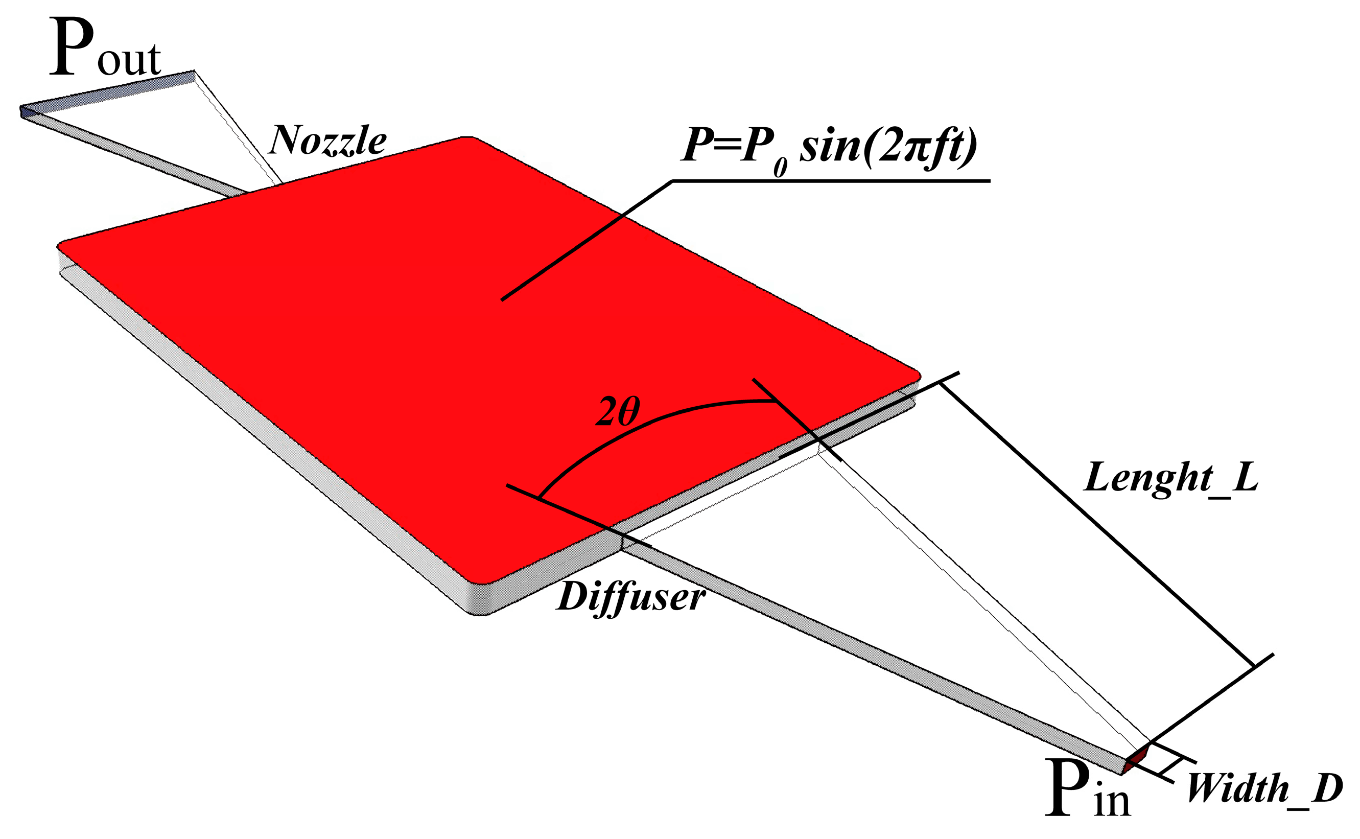
To find a better geometry for the air breathing pump, several simulations were performed using Fluent. The aspect ratio (AR, L/D), diffuser angle (θ), and opening width of the channel (D) are variables in the simulation model shown in Figure 1. The pressure change due to the vibrating PZT actuator was described as a specific user-defined function (UDF) shown in Equation (15) [15]. This UDF was connected to Fluent for the simulation model. The oscillation flow induced by the pressure change could thus be calculated.
The designs of the nozzle and the diffuser were used to achieve one-directional flow. The parameters rair,in and rair,out represent the performance of the nozzle and the diffuser, respectively. Figure 2 shows that rair,in was greater than 1.0 in the supply mode, which implies that the flow rate of the diffuser was higher than that of the nozzle. On the other hand, rair,out was less than 1.0 in the pump mode, which implies that the flow rate of the nozzle was higher than that of the diffuser. The highest rair,in of 1.55 was attained when the diffuser had an angle (θ) of 15°, when the opening width of the channel was (D) 1.0 mm, and the channel path (L) was 13.13 mm. In a previous study [16], the air inflow obtained had been 8.51 × 10⁻⁸ m3·s−1 on the diffuser side in supply mode when the angles of both the diffuser and the nozzle had been maintained at 10°. In this study, the obtained air inflow was 8.87 × 10⁻⁸ m3·s−1 on the diffuser side in supply mode. Hence, the modified design recorded a higher air inflow on the diffuser side. The geometric parameters of the diffuser were then determined for the experiments by choosing the maximum value of this inflow ratio, which implied that a large amount of air was supplied to the chamber.
The results of the simulation can be summarized as follows:
- In the supply mode:
- In the transition mode:
- In the pump mode:
2.2. Influence of Magnetic Force on PDMSmag
In Figure 3, the deflection of the rectangular PDMS (all edges fixed) loaded at the center (wcenter) is expressed by Equations (19) and (20) [21]:
The force between the cylindrical magnets is expressed as Equation (21) [22]:
The total force FPDMS(right) applied to the center of the PDMSmag (right) consisted of the repulsive force F(x1) between the PZTmag and the PDMSmag (right) and the attractive force F(x2) between the PDMSmag (right) and the PDMSmag (left):
The magnetic force was applied to the center of the PDMSmag (right). Substituting FPDMS(right) into Equation (19), the deflection at the center of the PDMSmag (right) is derived by Equation (23):
It is clear that the amplitudes of the vibrational motions of the PZTmag and the PDMSmag were affected by both the size of the magnets and the distance between them. The thickness of the PDMS (hPDMS), its Young’s modulus (E), and Poisson’s ratio (ν) were also affected by the stiffness of the PDMS. All the above parameters are thus very important to the design of the bi-cell PZTmag–PEMFC stack. Their effects are discussed below.
3. Development of Bi-Cell PZTmag–PEMFC Stack
3.1. Geometries
In this study, the PZT–PDMS actuator (BM 70/25/200M, Piezomechanik Dr. Lutz Pickelmann GmbH, München, Germany), located in the middle layer of the bi-cell PZTmag–PEMFC stack, was defined as the active component layer, which was the only layer that needed a power input. An 18 × 23 × 1.75 mm air pump chamber consisting of the PZT–PDMS actuator and a gasket was used. Adjacent to the active component layer were cathode flow field plates, MEAs, anode flow field plates, and anode current collectors, which formed a bi-cell stack. We defined this 48 mm × 49.26 mm × 12.5 mm bi-cell stack as the active component bi-cell PZT-PEMFC. Adjacent to each side of the active component bi-cell PZT-PEMFC was a bi-cell PEMFC without PZT, defined as the passive component bi-cell PEMFC. Between the active component bi-cell PZT-PEMFC and the passive component bi-cell PEMFC, a glass fiber plate was used as an insulator.
To drive the air pumps of the passive and active components simultaneously, NdFeB magnets were installed on the PDMS of each component (PDMSmag). Owing to the repulsive force between the two magnets, the air pump of the passive component functioned along with the air pump of the active component without additional power consumption. The magnet was placed at the bottom edge of the PZT actuator, where the center of the magnet aligned with the horizontal central line of the PDMS. The vertical distance between the bottom margin of the PDMS and the center of the magnet was 11.5 mm. The centers of the active and the passive magnets were fixed such that their centers were aligned; this caused a uniform repulsive force between them. The distance between active magnet and the passive magnet was 13.5 mm.
The PZT actuator operated in the air pump chamber with a limited geometric volume. However, if the magnets had been very large, they would have hit the cathode flow field plate and the current collector plate. This would have damaged the magnet and weakened the magnetic force. The arrangement of the active and passive magnets is presented in Table 1.
Due to the design of the bi-cell stack, the air pump provided a sufficient amount of air to both single cells simultaneously. Moreover, to simplify the hydrogen pipeline, manifolds were developed to uniformly provide hydrogen to each cell using only one pipeline. The total volume of the bi-cell PZTmag–PEMFC stack was 48 × 49.26 × 47.5 mm.
3.2. Manufacture
The bi-cell PZT-PEMFC stack proposed in this study consisted of 18 copper metal components, six graphite plates, each with a 48 × 49.26 mm cross-section, three acrylic plates, and two fiberglass plates. These are referred to as the current collector, the flow field plate, and the gaskets, respectively. They were assembled with six MEA films to form the stack consisting of a bi-cell PZT–PEMFC and two bi-cell PEMFCs. Each component of the stack was fabricated by a CNC machine, which was a three-axis CNC milling system with a precision of 0.01 mm and repeatability of 0.005 mm. The base material of the anode current collectors, the cathode current collectors, and the cathode flow field plates was copper, the anode flow field plates were graphite plates, the PZT actuator layer was composed of acrylic sheets, and the insulating layers were made of fiberglass. After the milling process, gold plating was performed on the copper components, which enhanced their metallic conductivity and resistance to oxidation.
PDMS (SYLGARD 184 silicone elastomer), known as poly-di-methyl-siloxane, was supplied in two parts as the base material and curing agent, which were mixed in a ratio of 10:1 (base: curing agent) by weight. The polytetrafluoroethene (Teflon®) molds, which were used in the curing process, were fabricated by a highly accurate CNC machine. The molds were placed along with the mixture in a vacuum chamber for one hour to remove air bubbles prior to curing. The molds and the mixture were then heated and cured at a constant temperature of 100 °C in an oven. Once the PDMS was solidified, a PZT actuator was combined with the PDMS: this is referred to as a PZT–PDMS actuator. Furthermore, the combination of a PZT–PDMS actuator and a magnet is called a PZTmag actuator.
The PZTmag actuator was installed on an acrylic plate and clamped by a gasket. The cathode flow field plate, the MEA, and the anode flow field plate were clamped between the anode current collector layer and the gasket, as shown in Figure 4. The layers were held together by screws instead of glue. Hence, every part of the bi-cell PZTmag–PEMFC stack could be separately changed.
4. Experimental Set-Up
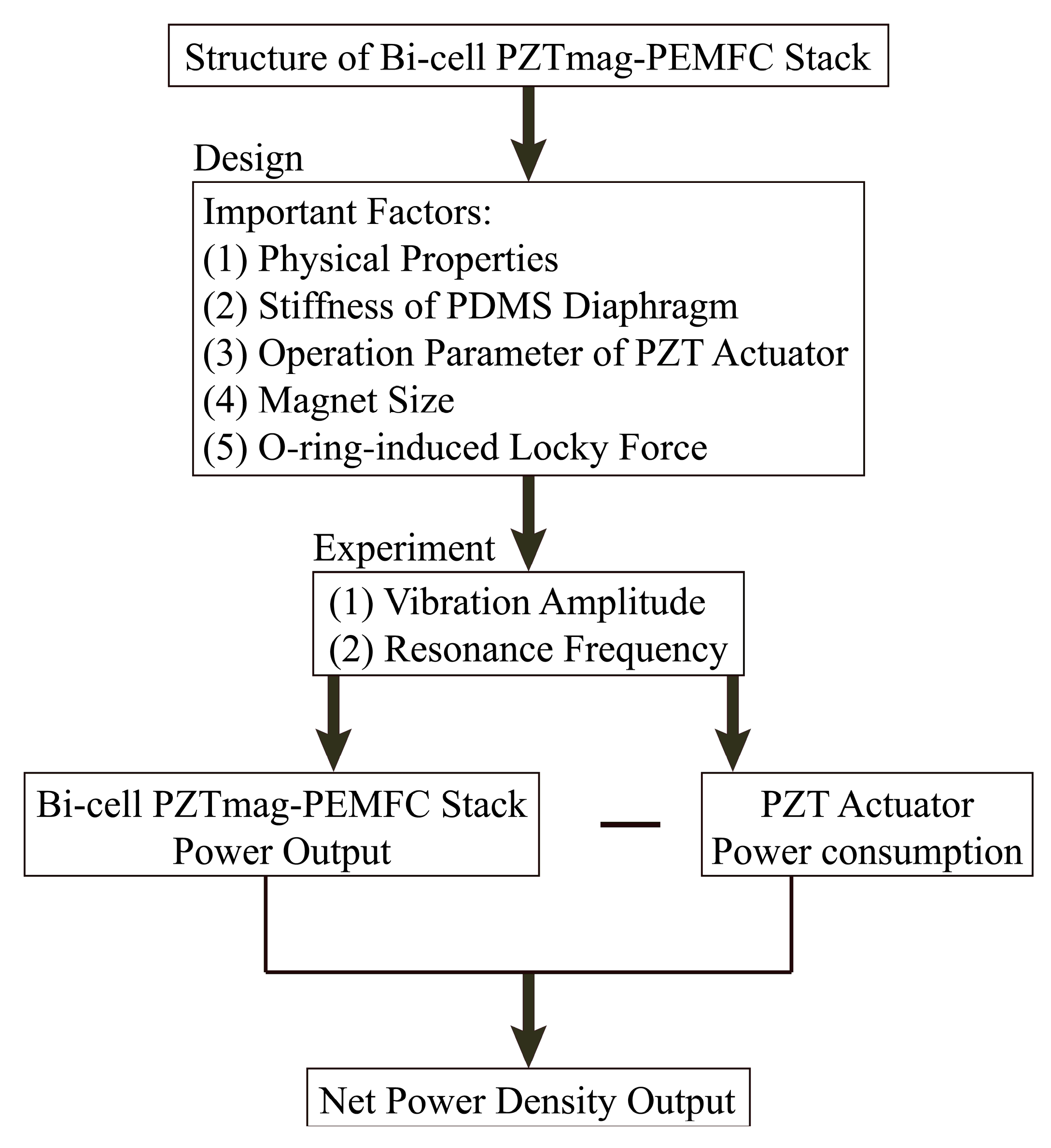
The experiment flowchart of bi-cell PZTmag-PEMFC stack is shown in Figure 5. According to the specifications of the PZT actuator (BM 70/25/200M, Piezomechanik Dr. Lutz Pickelmann GmbH, München, Germany), the maximum operating voltage was 50 V and the operating frequency was below 300 Hz. In this experiment, its proper operation, the PZT actuator was tested at an rms voltage of 10–40 V and a frequency of 15–270 Hz.
4.1. Analysis of PZT Actuation
The curing time of the PDMS not only influenced the Young’s modulus, but also the resonance frequency of the PZT–PDMS. To determine how the mechanical properties of the PDMS affected the air inflow of the pump, the PDMS molding process had to be well designed. To determine how the resonance frequency was affected by curing time, the PDMS was cured in an oven at 100 °C with different curing times of 30, 45, and 60 min. The mechanical properties of the PDMS diaphragm at different curing times are listed in Table 2. These diaphragms were tested in the amplitude experiment of the PZT actuator.
The PZT actuator was installed on an acrylic plate and clamped by two gaskets; it was then fixed on the testing platform. A functional generator was used to deliver sine wave signals to cause vibrations in the PZT actuator. The components of the PZT actuator could accept an AC sine wave signal as well. When the voltage changed with time, the electric field changed on both sides of the PZT actuator, which led to lattice deformation. This deformation produced vibrations in the PZT actuator when one side was fixed and the other was free. Signals from the function generator were sent to an amplifier for magnification and delivered to the PZT actuator through signal wires. A power meter was connected to the output terminal of the amplifier to measure the power consumption of the PZT actuator. At the same time, the amplitude of the PZT–PDMS actuator was measured by a fiber-optic Fotonic Sensor (MTI 2100, Mechanical Technology, Incorporated, New York, NY, USA) with a number of experimental parameters. The experimental instruments were set as seen in Figure 6. The performance of the actuators was assessed using the measured amplitudes and power consumption. As a result, the PDMSs that caused the PZT actuator to generate the largest amplitude were used in the active component and the passive component in the following experiments. Then, we assembled the bi-cell PZTmag–PEMFC stack in which the passive component of the PDMS was combined with different magnets. Finally, the three components of the stack were fixed on the testing platform at a distance of 13.5 mm, as shown in Figure 6c.
4.2. Analysis of Bi-Cell PZTmag–PEMFC Stack
In this experiment, we use the same concept of the PZT-PEMFC to build the stack with the same MEA reaction area as that used in previous studies. In addition, we tested the fuel cell stack using the same experimental platform. A hydrogen flow controller connection (Alicat mass flow controller) was used to stabilize hydrogen supply to the bi-cell PZTmag–PEMFC stack anode. The volume of the flow rate was maintained at 180 mL·min−1 (60 mL·min−1 per bi-cell). A single cell contained a total reaction area of 2 × 2 cm2 (the membrane was Nafion®212). The PZT actuator was used to enhance airflow to the cathode. The constant voltage mode of the electronic load was chosen under an electrical series configuration. The performance of the bi-cell PZTmag–PEMFC stack was measured.
5. Results and Discussion
In this study, the air pump of the bi-cell PZTmag–PEMFC stack that was used had an aspect ratio of 13.13, a diffuser angle (θ) of 15°, and a channel opening width (D) of 1.0 mm. The stack operated under an rms voltage of 40 V and a temperature of 25 °C. The PZT actuator was integrated with the PDMS by curing for 30 min at 100 °C. These operating parameters were used to study the vibrating amplitudes and power consumption of the PZT actuator as well as the effect of the magnetic force on the amplitudes and resonance frequencies of the bi-cell PZTmag–PEMFC stack.
5.1. Influence of PDMS Curing Time on PZT Actuator
The resonant frequency of the PZT actuator was significantly affected by the stiffness of the PDMS diaphragm, thereby leading to varying overall performance. Since thin PDMS diaphragms are difficult to manufacture and tend to crack during vibrations, special curing times were chosen to analyze the influence of the stiffness of the diaphragm on the performance of the PZT actuator. Accordingly, diaphragms were fabricated at curing times of 30, 45, and 60 min. The experiment results offered a comparison of the vibrating amplitudes and the frequencies at varying curing times. The PZT actuator with a 30-min curing time had a maximum amplitude of 1602 μm when operating at 40 V and 135 Hz, the PZT actuator with a 45-min curing time had a maximum amplitude of 1581 μm when operating at 40 V and 150 Hz, and that with a 60-min curing time had a maximum amplitude of 1559 μm when operating at 40 V and 160 Hz. A longer curing time led to higher stiffness, which resulted in smaller amplitudes. As a result, the PDMS with the 30-min curing time had the largest amplitude of vibration.
The power consumption values that generate the maximum vibrating amplitudes may differ with PZT actuator design. Table 3 lists the power consumption for the maximum vibrating amplitudes for each design at 40 V. The PDMS with a 30-min curing time induced a maximum amplitude of 1602 μm with 135 Hz and 40 V, while the power consumption was only 0.073 W; this was the considered the best design for future applications.
The actuating voltage for the tests was 40 V. All maximum vibrating amplitudes of the PDMS with 30-, 45-, and 60-min curing times were over 1500 μm. However, the power consumption of each design was different because of the varying stiffness and thus, the resonant frequencies. The performance of the PZT (the vibrating amplitude per power consumption for the PZT device) was calculated and is shown in Figure 7. The highest PZTM value was attained with 135 Hz and 40 V when the PDMS with 30-min curing time was used.
5.2. Influence of Magnet Size on PZTmag Actuator
When the PZTmag used a magnet 6 mm in diameter and 1 mm in thickness, the PDMSmag used magnets that were 6 mm, 5 mm, 4 mm, and 3 mm in diameters and 1 mm in thickness. Once the PZT actuator was integrated with the magnet, which increased the total mass, both the resonance frequency and the amplitude decreased. When the PZTmag actuator used a magnet 6 mm in diameter and the PDMSmag used magnets 3 mm in diameter, a maximum amplitude of 280 μm was produced with 95 Hz and 40 V.
5.3. Influence of O-Rings within a PZTmag–PEMFC Stack
Once all stack components had been assembled, the PZTmag used a magnet 6 mm in diameter, whereas the PDMSmag used magnets of diameters 6 mm, 5 mm, 4 mm, and 3 mm. We used O-rings to prevent the flow field plate from leaking hydrogen. The installation of the O-rings increased the thickness of the stack, which in turn increased the distance between the centers of the air pumps. To fix a distance of 13.5 mm to the center of the air pump, we needed to apply a greater locking force to assemble the stack. Because of the greater force, the PDMS sustained a larger tension force. Therefore, larger magnets were used to strengthen the magnetic force to contend against the larger tension force within the PDMS. This is shown in the experimental results when both the PZTmag and the PDMSmag used magnets 6 mm in diameter. The experimental result for the bi-cell PZTmag–PEMFC stack is shown in Figure 8. In this experiment, a maximum amplitude of 87 μm was produced under operating conditions of 70 Hz and 40 V. The power consumption was 0.03 W.
5.4. Performance of Bi-Cell PZTmag–PEMFC Stack
5.4.1. Effect of Each Bi-Cell on PDMS and PZTmag Actuator
According to the experimental results shown in Figure 9, pumping air did not work when the PDMS was not aided by the magnets. The air pump did not facilitate the electrochemical reaction in the fuel cell and, hence, did not allow the bi-cell PEMFC to generate power because the vibration of the PDMSmag was entirely dependent on the magnet repulsion force of the PZTmag to promote.
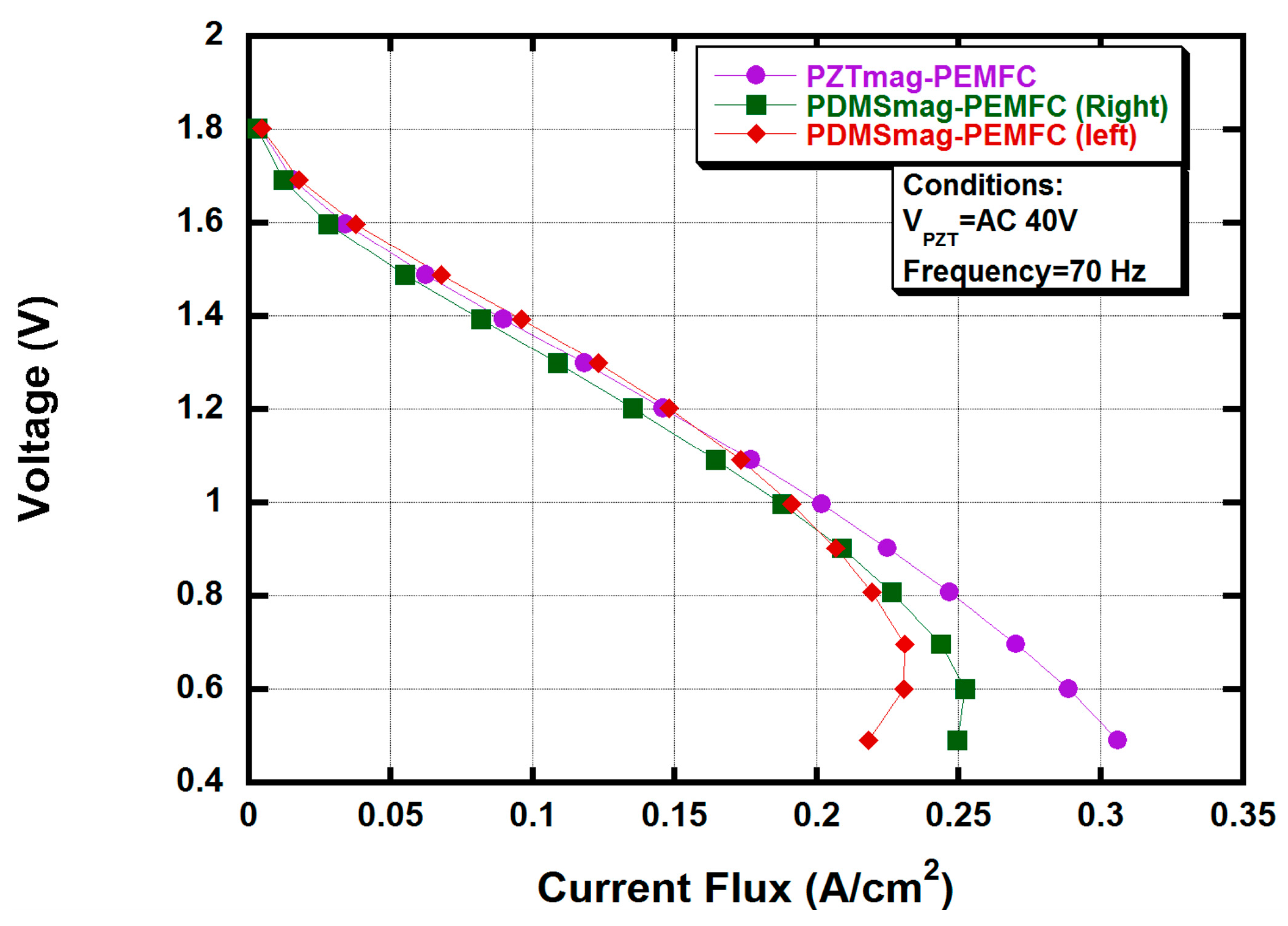
Moreover, the experimental results showed that the I-V curve of the PZTmag-PEMFC was more stable than those of the other two PDMSmag–PEMFCs as shown in Figure 10. This was because the PDMSmag was driven by the PZTmag in only one direction. When the PZTmag pushed in the opposite direction, the PDMSmag returned to its original position because of its own tension. Therefore, the vibration in the PDMSmag was limited, resulting in different amplitudes in the forward and backward directions. A maximum amplitude of 87 μm was produced under operating conditions of 70 Hz and 40 V. Furthermore, because of the smaller amount of air pumped into the chamber, the power generated by the three bi-cells was lower than expected. The maximum power flux outputs were 0.2025 W·cm−2, 0.1888 W·cm−2, and 0.1913 W·cm−2.
5.4.2. Net Power Output of the Bi-Cell PZTmag–PEMFC Stack
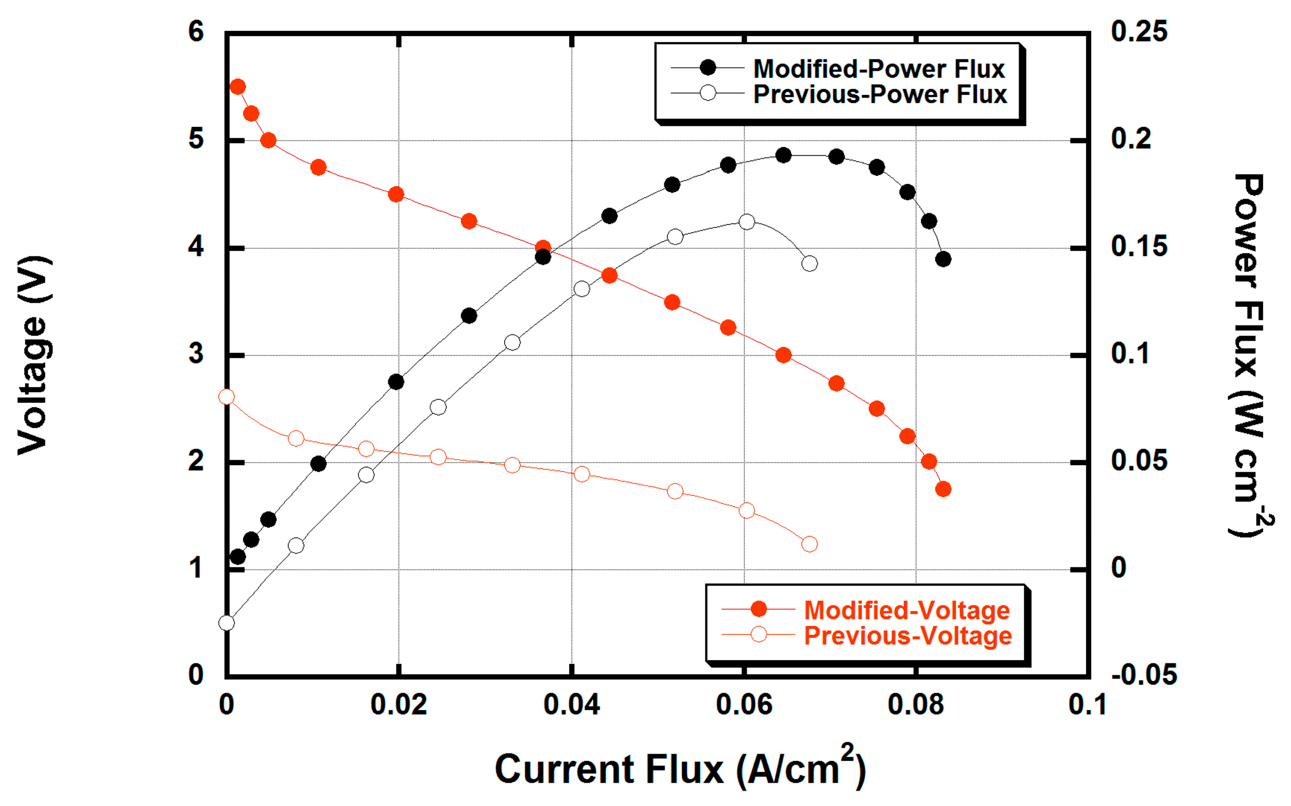
The optimized design (both PZTmag actuator and PDMSmag combined with the magnet of diameter 6 mm) was used to measure the power outputs for certain tests. The power consumption of the PZTmag actuator under a frequency of 70 Hz and voltage of 40 V was 0.03 W, while the power output of the bi-cell PZTmag–PEMFC stack wFas 4.65 W. Thus, the module of the bi-cell PZTmag–PEMFC stack delivered a net power output of 4.62 W (the output in [16] was 3.86 W). The comparison with previously proposed fuel cell stack designs is shown in Figure 11. The maximum net power flux output of the bi-cell PZTmag–PEMFC stack in the series was 0.1925 W·cm−2, compared to 0.1608 W·cm−2 in the previous design [16]. The net power flux output of the stack hence approximately increased by 20%.
6. Conclusions
In this study, a PZT actuator with a magnetically driven design for a PZT-PEMFC stack was developed. Three air breathing pumps of a bi-cell PZTmag–PEMFC stack were driven by only one piezoelectric actuator through a magnetic repulsive force between the magnets. As a result, the total volume and weight of the stack were reduced to 97.5 cm3 and 553 g, respectively. Compared with a previous design [16], the total volume and weight were reduced by 68% and 76%, respectively. The results of this study can be summarized as follows: First, the PZT actuator (with a curing time of 30 min for the PDMS) produced the largest amplitude of 1602 μm at a frequency of 135 Hz and voltage of 40 V. The power consumption was 0.073 W. Second, the tension in the PDMS was higher when the bi-cell PZTmag–PEMFC stack was assembled by a greater locking force, which reduced the resonance frequency and the amplitude of the PZTmag actuator. Larger magnets were used to strengthen the magnetic force that could push the PDMS, which has a larger tension. When both the PZTmag and the PDMSmag used magnets 6 mm in diameter, a maximum amplitude of 87 μm was produced under operating conditions of 70 Hz and 40 V. The power consumption was 0.03 W. Finally, when both the PZTmag and the PDMSmag used magnets 6 mm in diameter, the net power flux output of the bi-cell PZTmag–PEMFC stack was 0.1925 W·cm−2, which was a 20% increase over a previous design of the stack [16].
Acknowledgments
This research was funded by the National Taiwan University and Ministry of Science and Technology.
Author Contributions
Hsiaokang Ma proposed the idea and supervised the work. Yuanlung Hsu and Poching Hsu built the initial constructs, co-designed and performed the experiments, provided experimental data and analyzed them, and co-wrote the manuscript.
Conflicts of Interest
The authors declare no conflict of interest.
Nomenclature
| APZT | Piezoelectric area (m2) |
| AR | Aspect ratio |
| a | The width of rectangular PDMS (mm) |
| B0 | Magnetic flux density |
| b | The length of rectangular PDMS (mm) |
| C | Conductivity coefficient |
| Cn | Nozzle conductivity coefficient |
| Cd | Diffuser conductivity coefficient |
| D | Channel opening width (mm) |
| E | The Young’s modulus of PDMS |
| F | Force between two cylindrical magnets applied at the center of rectangular PDMS (N) |
| f | Frequency of PZT (Hz) |
| hPDMS | The thickness of PDMS (mm) |
| hmag | The height of magnet (mm) |
| L | Channel path (mm) |
| P | Pressure (N·m−2) |
| Pc | Channel pressure (N·m−2) |
| Pin | Inlet pressure (N·m−2) |
| Pout | Outlet pressure (N·m−2) |
| PZTM | Vibrating amplitude per power consumption for the PZT (mm/W) |
| Q | Airflow rate (m3·s−1) |
| Qin,total | Total flow rate (m3·s−1) |
| Qin,n | Inlet flow rate from the nozzle (m3·s−1) |
| Qout,n | Outlet flow rate from the nozzle (m3·s−1) |
| Qin,d | Inlet flow rate from the diffuser (m3·s−1) |
| Qout,d | Outlet flow rate from the diffuser (m3·s−1) |
| R | Gas constant (J·mol−1·K−1) |
| rair,in | In supply mode, the ratio of air inflow |
| rair,out | In pump mode, the ratio of air outflow |
| r | The radius of magnet |
| t | Time (s) |
| T | Temperature (K) |
| VPZT | Motion equation of the piezoelectric device (m3·s−1) |
| ν | The Poisson’s ratio of PDMS |
| wcenter | Deflection at the center of rectangular PDMS |
| x | Distance between two magnets |
| α | The coefficient decided by b/a |
| Loss coefficient | |
| Λ | Amplitude (μm) |
| θ | Diffuser angle |
| ρ | Density (kg·m−3) |
| μ0 | The permeability of free space |
| ∀ | Volume displacement (m3) |
References
- Li, X.; Sabir, I. Review of bipolar plates in pem fuel cells: Flow-field designs. Int. J. Hydrog. Energy 2005, 30, 359–371. [Google Scholar] [CrossRef]
- Wang, J.; Wang, H. Flow-field designs of bipolar plates in pem fuel cells: Theory and applications. Fuel Cells 2012, 12, 989–1003. [Google Scholar] [CrossRef]
- Böhm, S.; Olthuis, W.; Bergveld, P. A plastic micropump constructed with conventional techniques and materials. Sens. Actuators A Phys. 1999, 77, 223–228. [Google Scholar] [CrossRef]
- Yamahata, C.; Lotto, C.; Al-Assaf, E.; Gijs, M.A.M. A pmma valveless micropump using electromagnetic actuation. Microfluid. Nanofluid. 2005, 1, 197–207. [Google Scholar] [CrossRef]
- Olsson, A.; Stemme, G.; Stemme, E. Diffuser-element design investigation for valve-less pumps. Sens. Actuators A Phys. 1996, 57, 137–143. [Google Scholar] [CrossRef]
- Stemme, E.; Stemme, G. A valveless diffuser/nozzle-based fluid pump. Sens. Actuators A Phys. 1993, 39, 159–167. [Google Scholar] [CrossRef]
- Wang, B.; Chu, X.; Li, E.; Li, L. Simulations and analysis of a piezoelectric micropump. Ultrasonics 2006, 44, e643–e646. [Google Scholar] [CrossRef] [PubMed]
- Benard, W.L.; Kahn, H.; Heuer, A.H.; Huff, M.A. Thin-film shape-memory alloy actuated micropumps. J. Microelectromech. Syst. 1998, 7, 245–251. [Google Scholar] [CrossRef]
- Olivier, F.; Isabelle, D.; Emmanuel, S. Analytical static modelling and optimization of electrostatic micropumps. J. Micromech. Microeng. 1997, 7, 183. [Google Scholar]
- Wego, A.; Glock, H.W.; Pagel, L.; Richter, S. Investigations on thermo-pneumatic volume actuators based on pcb technology. Sens. Actuators A Phys. 2001, 93, 95–102. [Google Scholar] [CrossRef]
- Kim, E.G.; Oh, J.G.; Choi, B. A Study on the development of a continuous peristaltic micropump using magnetic fluids. Sens. Actuators A Phys. 2006, 128, 43–51. [Google Scholar] [CrossRef]
- Lemoff, A.V.; Lee, A.P. An ac magnetohydrodynamic micropump. Sens. Actuators B Chem. 2000, 63, 178–185. [Google Scholar] [CrossRef]
- Zhong, J.; Yi, M.; Bau, H.H. Magneto hydrodynamic (mhd) pump fabricated with ceramic tapes. Sens. Actuators A Phys. 2002, 96, 59–66. [Google Scholar] [CrossRef]
- Ma, H.K.; Huang, S.H.; Chen, B.R.; Cheng, L.W. Numerical study of a novel micro-diaphragm flow channel with piezoelectric device for proton exchange membrane fuel cells. J. Power Sources 2008, 180, 402–409. [Google Scholar] [CrossRef]
- Ma, H.K.; Huang, S.H.; Wang, J.S.; Hou, C.G.; Yu, C.C.; Chen, B.R. Experimental study of a novel piezoelectric proton exchange membrane fuel cell with nozzle and diffuser. J. Power Sources 2010, 195, 1393–1400. [Google Scholar] [CrossRef]
- Ma, H.K.; Cheng, H.M.; Cheng, W.Y.; Fang, F.M.; Luo, W.F. Development of a piezoelectric proton exchange membrane fuel cell stack (pzt-stack). J. Power Sources 2013, 240, 314–322. [Google Scholar] [CrossRef]
- Fuard, D.; Tzvetkova-Chevolleau, T.; Decossas, S.; Tracqui, P.; Schiavone, P. Optimization of Poly-di-Methyl-Siloxane (pdms) substrates for studying cellular adhesion and motility. Microelectron. Eng. 2008, 85, 1289–1293. [Google Scholar] [CrossRef]
- Ma, H.K.; Su, H.C.; Luo, W.F. Investigation of a piezoelectric fan cooling system with multiple magnetic fans. Sens. Actuators A Phys. 2013, 189, 356–363. [Google Scholar] [CrossRef]
- Ullmann, A. The piezoelectric valve-less pump—Performance enhancement analysis. Sens. Actuators A Phys. 1998, 69, 97–105. [Google Scholar] [CrossRef]
- Tsui, Y.Y.; Lu, S.L. Evaluation of the performance of a valveless micropump by cfd and lumped-system analyses. Sens. Actuators A Phys. 2008, 148, 138–148. [Google Scholar] [CrossRef]
- Timoshenko, S.; Woinowsky-Krieger, S. Theory of Plates and Shells; McGraw-Hill: New York, NY, USA, 1959. [Google Scholar]
- Furlani, E.P. Chapter 3—Field Analysis. In Permanent Magnet and Electromechanical Devices; Academic Press: San Diego, CA, USA, 2001; pp. 97–205. [Google Scholar]
- Mark, J.E. Polymer Data Handbook; Oxford University Press: Oxford, UK, 1999. [Google Scholar]
Figure 1.
Parameters of the design of the air pump chamber.

Figure 2.
Ratio of air inflow and outflow at a channel opening width of 1 mm.
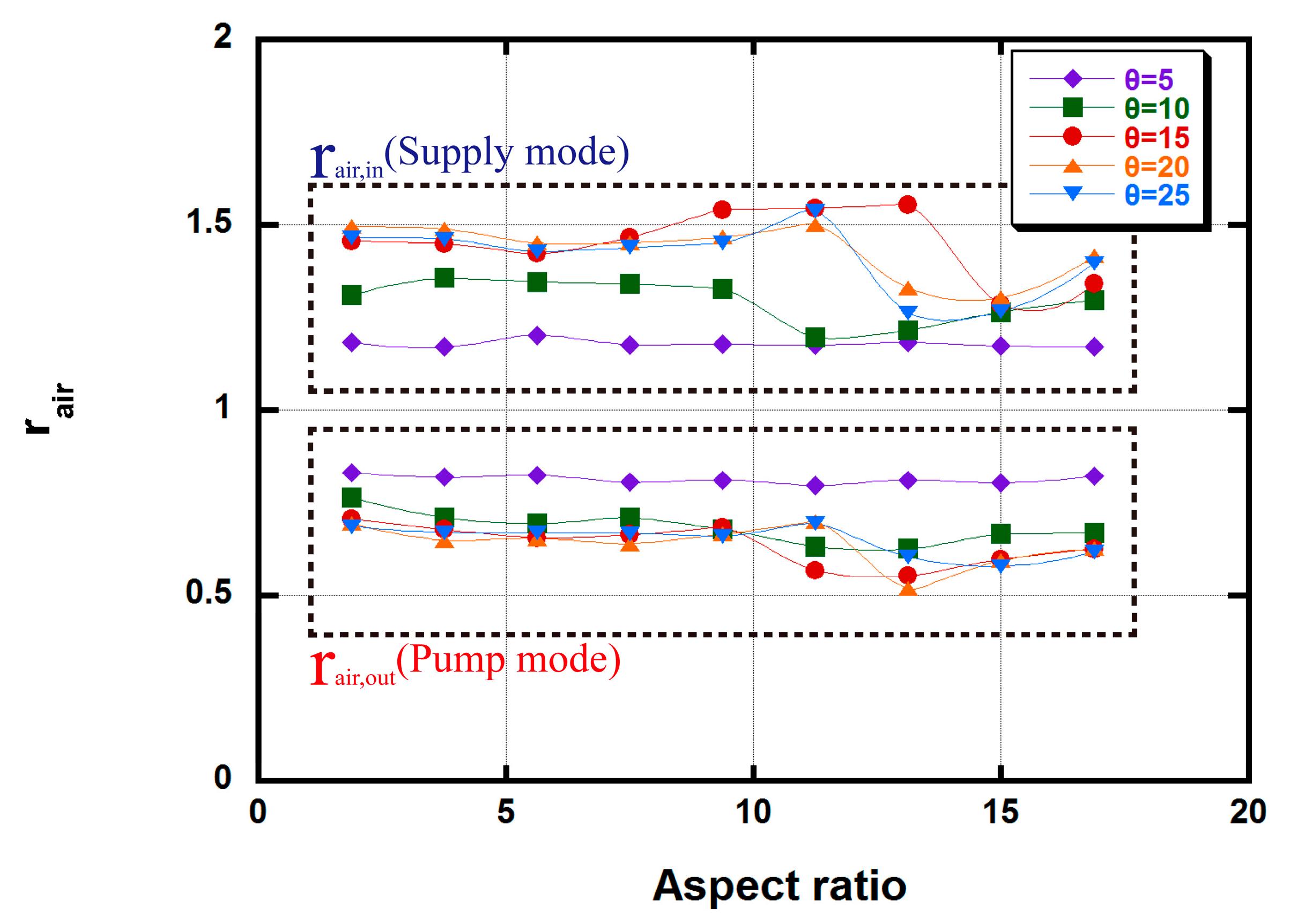
Figure 3.
Parameters of PZTmag and PDMSmag.
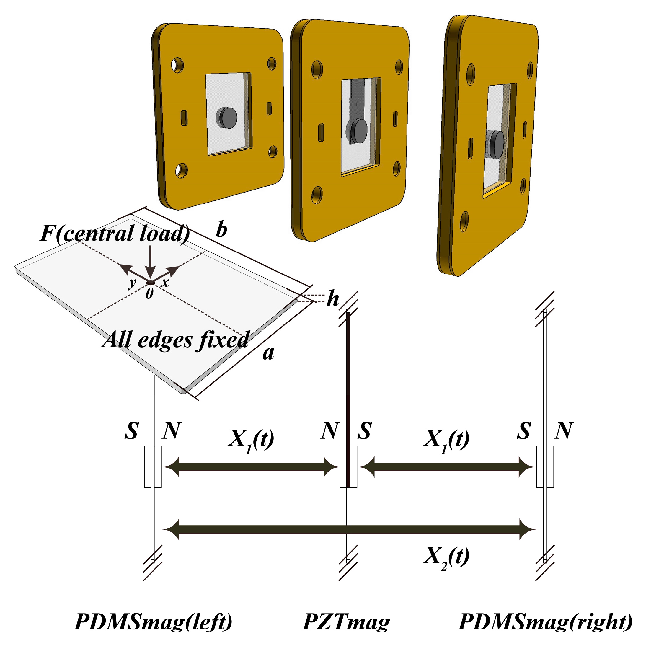
Figure 4.
Schematic diagram of the bi-cell PZTmag–PEMFC stack.

Figure 5.
Experiment flowchart of bi-cell PZTmag-PEMFC stack.

Figure 6.
Resonant frequency and amplitude test system of the PZT–PDMS actuator and the PDMSmag. (a) Platform for experimental instruments; (b) Measuring the PZT–PDMS; (c) Measuring the PDMSmag within a stack.
Figure 6.
Resonant frequency and amplitude test system of the PZT–PDMS actuator and the PDMSmag. (a) Platform for experimental instruments; (b) Measuring the PZT–PDMS; (c) Measuring the PDMSmag within a stack.

Figure 7.
Vibrating amplitude per power consumption of the PZT actuators.
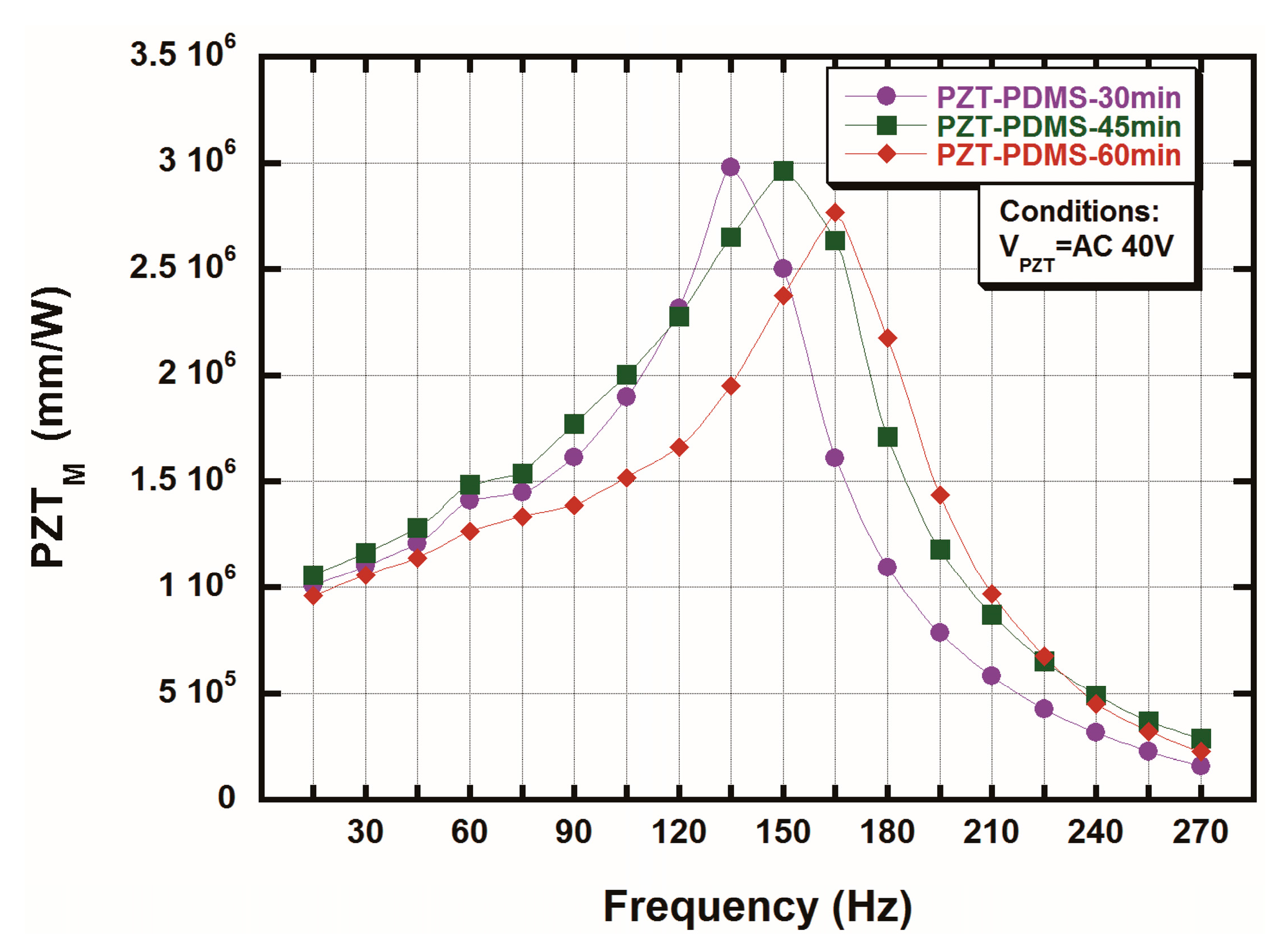
Figure 8.
Maximum amplitude of the PDMSmag at 40 V when the bi-cell PZTmag–PEMFC stack was assembled.
Figure 8.
Maximum amplitude of the PDMSmag at 40 V when the bi-cell PZTmag–PEMFC stack was assembled.
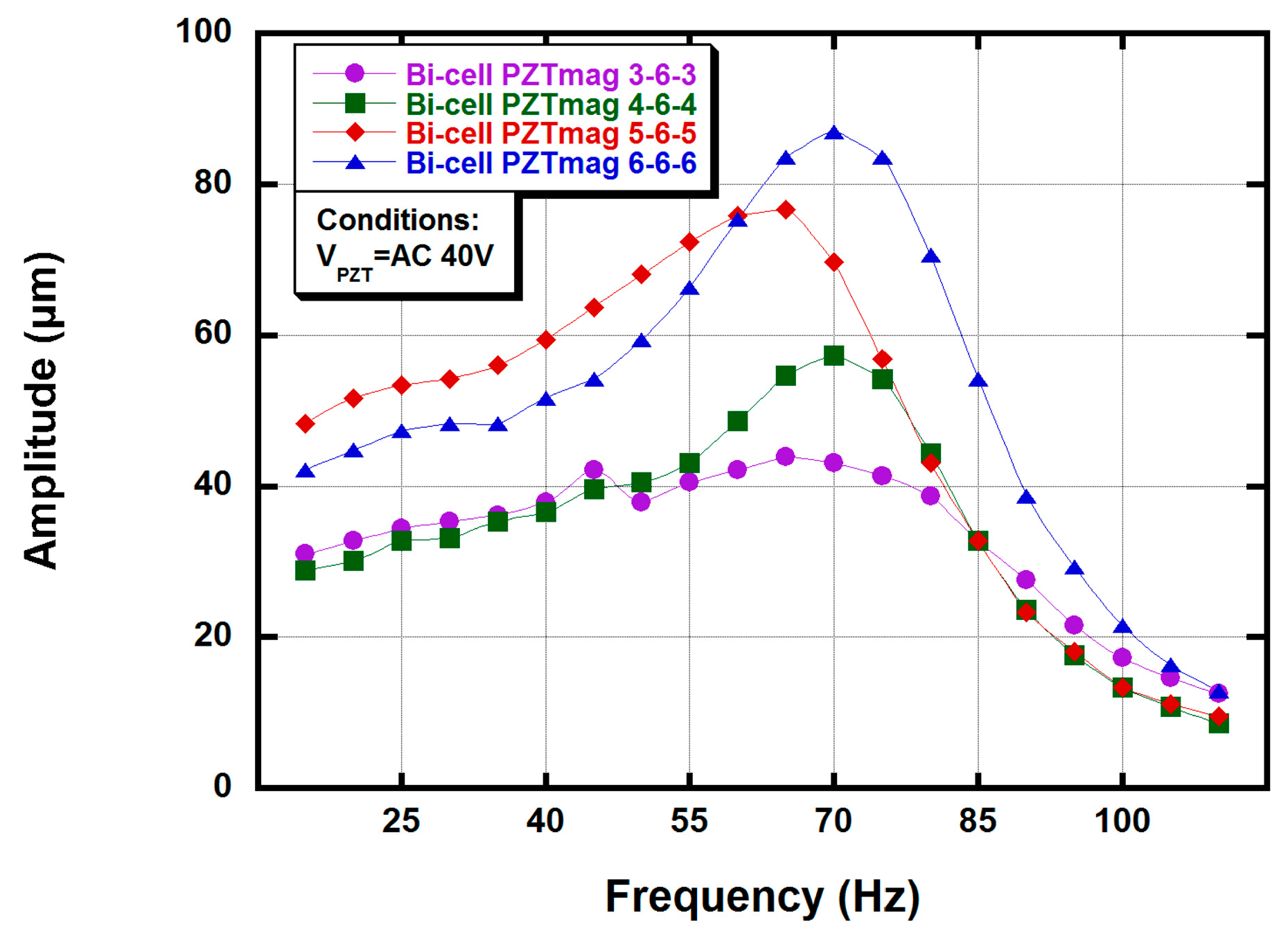
Figure 9.
PDMS without using the magnet with a bi-cell PEMFC.
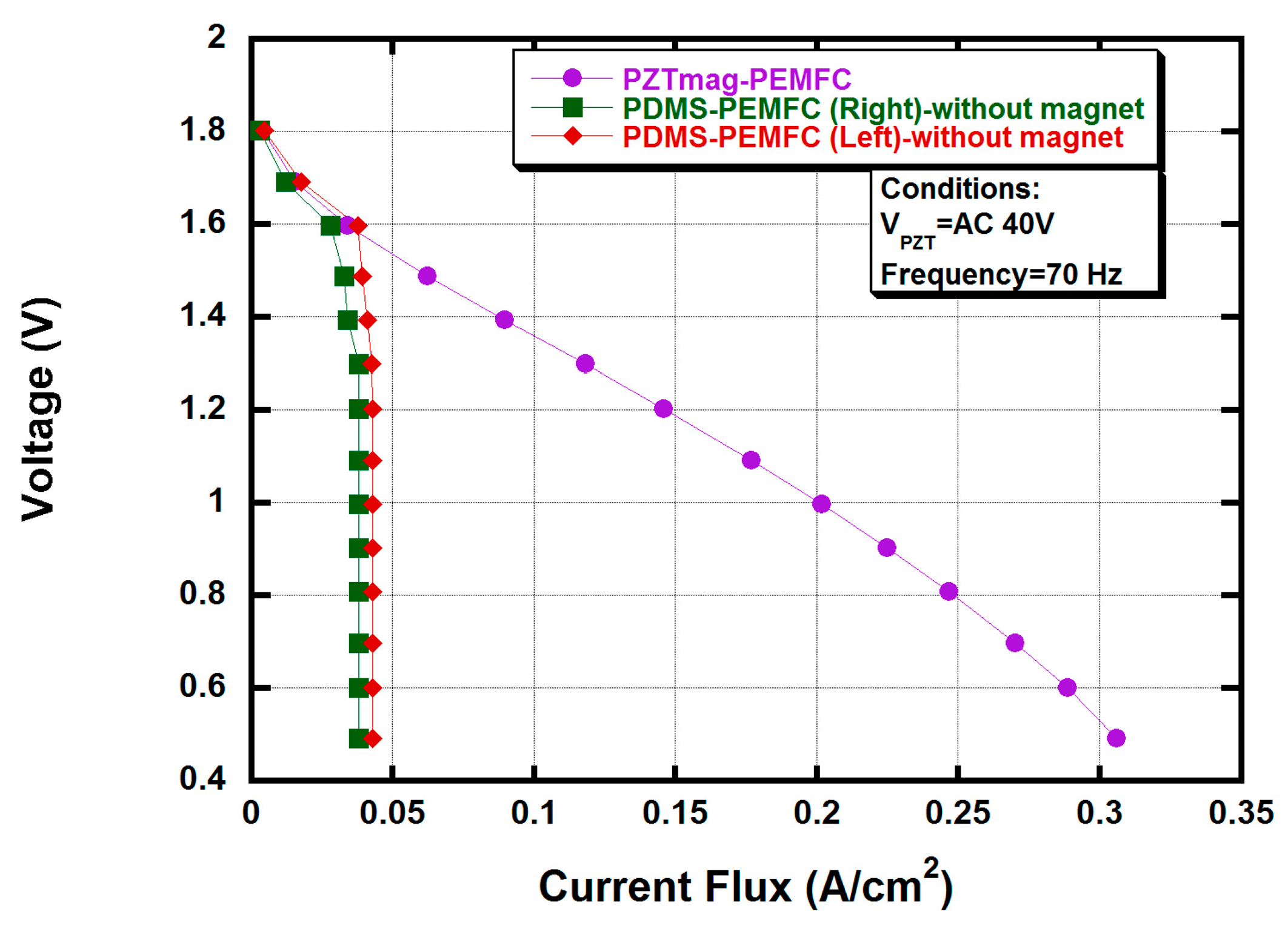
Figure 10.
PDMS combined with a magnet within a bi-cell PEMFC.

Figure 11.
Compared with previous designs of fuel cell stack.


Table 1.
Arrangement of active and passive magnets (diameter: mm).
| Serial Number | PDMSmag (Left) | PZTmag Actuator | PDMSmag (Right) |
|---|---|---|---|
| Arrangement-A | 6.0 mm | 6.0 mm | 6.0 mm |
| Arrangement-B | 5.0 mm | 6.0 mm | 5.0 mm |
| Arrangement-C | 4.0 mm | 6.0 mm | 4.0 mm |
| Arrangement-D | 3.0 mm | 6.0 mm | 3.0 mm |
Table 2.
Mechanical properties of PDMS diaphragm with different curing times.
| Serial Number | Curing Time at 100 °C | Young’s Modulus | Poisson’s Ratio [23] |
|---|---|---|---|
| PDMS-A | 30 min | 1250 kPa | 0.5 |
| PDMS-B | 45 min | 1375 kPa | 0.5 |
| PDMS-C | 60 min | 1625 kPa | 0.5 |
Table 3.
Power consumption of the maximum vibrating amplitudes of each design under 40 V.
| Serial Number | Amplitude/μm | Power Consumption/W | Frequency/Hz |
|---|---|---|---|
| PZT–PDMS-30 | 1602 | 0.073 | 135 |
| PZT–PDMS-45 | 1581 | 0.080 | 150 |
| PZT–PDMS-60 | 1559 | 0.093 | 165 |
© 2017 by the authors. Licensee MDPI, Basel, Switzerland. This article is an open access article distributed under the terms and conditions of the Creative Commons Attribution (CC BY) license (http://creativecommons.org/licenses/by/4.0/).
Share and Cite
MDPI and ACS Style
Ma, H.; Hsu, Y.; Hsu, P. A Novel Hybrid Actuator Driven Magnetically in the Bi-Cell PEM Fuel Cell Stack. Metals 2017, 7, 453. https://doi.org/10.3390/met7110453
AMA Style
Ma H, Hsu Y, Hsu P. A Novel Hybrid Actuator Driven Magnetically in the Bi-Cell PEM Fuel Cell Stack. Metals. 2017; 7(11):453. https://doi.org/10.3390/met7110453
Chicago/Turabian StyleMa, Hsiaokang, Yuanlung Hsu, and Poching Hsu. 2017. "A Novel Hybrid Actuator Driven Magnetically in the Bi-Cell PEM Fuel Cell Stack" Metals 7, no. 11: 453. https://doi.org/10.3390/met7110453
Note that from the first issue of 2016, this journal uses article numbers instead of page numbers. See further details here.