3.2. Effect of Solid Solution Heat Treatment on Hardness and Microstructure
Solid solution heat treatment (SSHT) was carried out to dissolve coarse primary precipitates in the matrix, which were then reprecipitated from supersaturated solid solution during the subsequent aging process with the purpose of precipitation strengthening. If the solution temperature is too low, large primary precipitates are difficult to dissolve into matrix. However, if the solid solution temperature is too high, austenitic grain size (AGS) will grow up excessively. The AGS tremendously influences diffusive and diffusionless phase transformations, precipitation, and mechanical properties such as strength, hardness, toughness, and ductility [
15]. Hence, the SSHT process is quite important for microstructures and mechanical properties. The effects of SSHT on the austenite grain size, microstructure, and Rockwell hardness were studied in detailed.
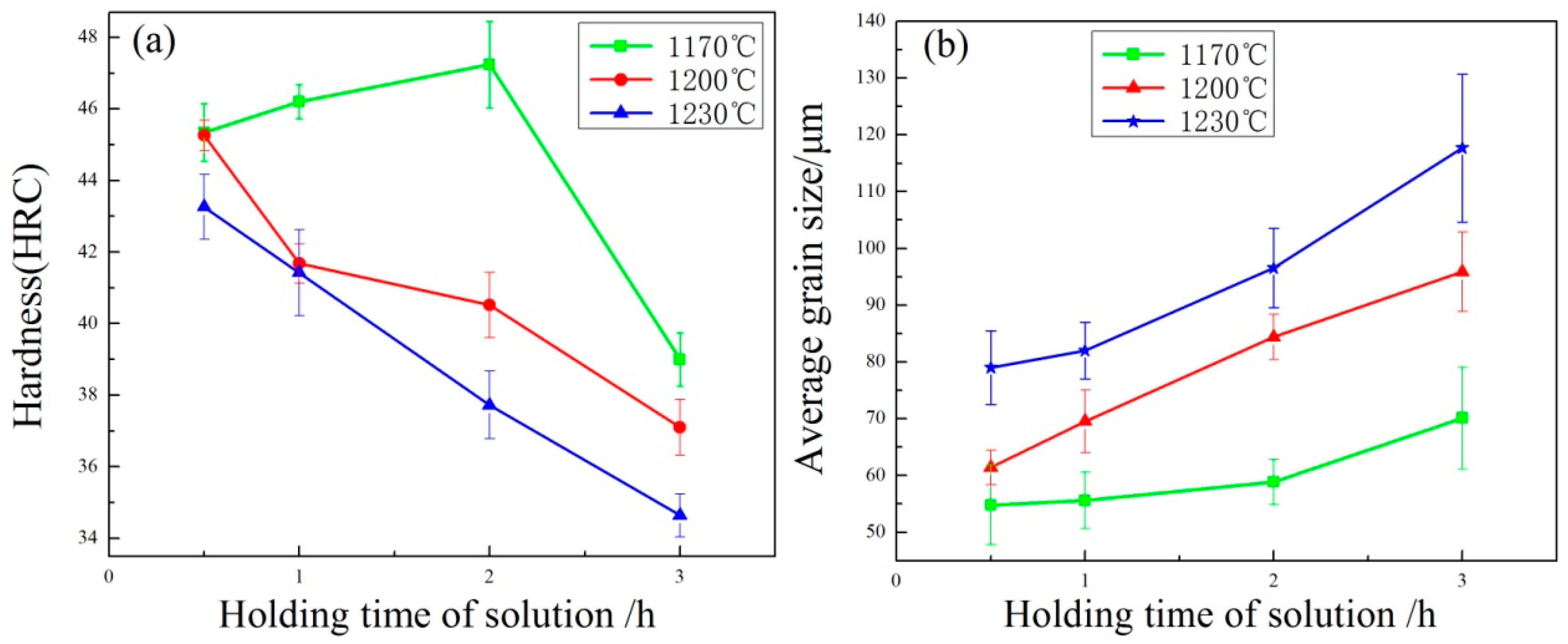
The hardness value of the specimens, which were subjected to various SSHT and the same aging treatment at 720 °C for 2 h, is shown in
Figure 7a. The hardness value increased from 45.34 HRC to 47.24 HRC at a solution temperature of 1170 °C with increasing solution time from 0.5 h to 2 h. However, the hardness value decreased rapidly to 39 HRC when the solid solution time was 3 h at 1170 °C. When the solid solution temperature reached 1200 °C and 1230 °C, the hardness decreased linearly with the increase of solution holding time from 0.5 h to 3 h.
The AGS after different solution heat treatments is shown in
Figure 7b. The austenite grain grew gradually with increasing solution temperature and solution time. The austenite grains grew slowly at a solution temperature below 1200 °C. A tangible grain growth was detected at 1170 °C for soaking times over 3 h due to the coupled effects of the soaking time and temperature on the grain growth. The results presented in
Figure 7b also implied that the effect of solution temperature on grain growth was more noticeable than solution time.
Figure 8 and
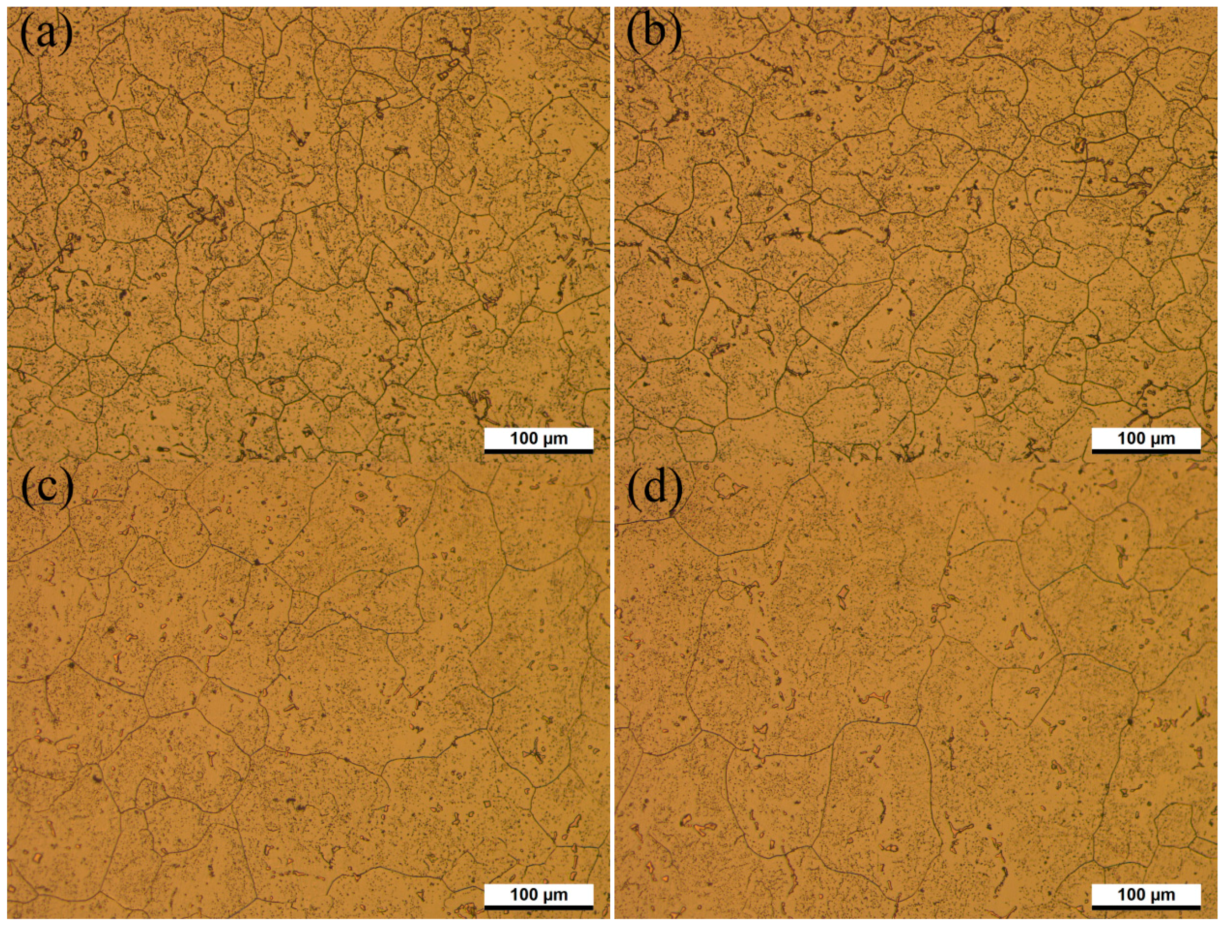
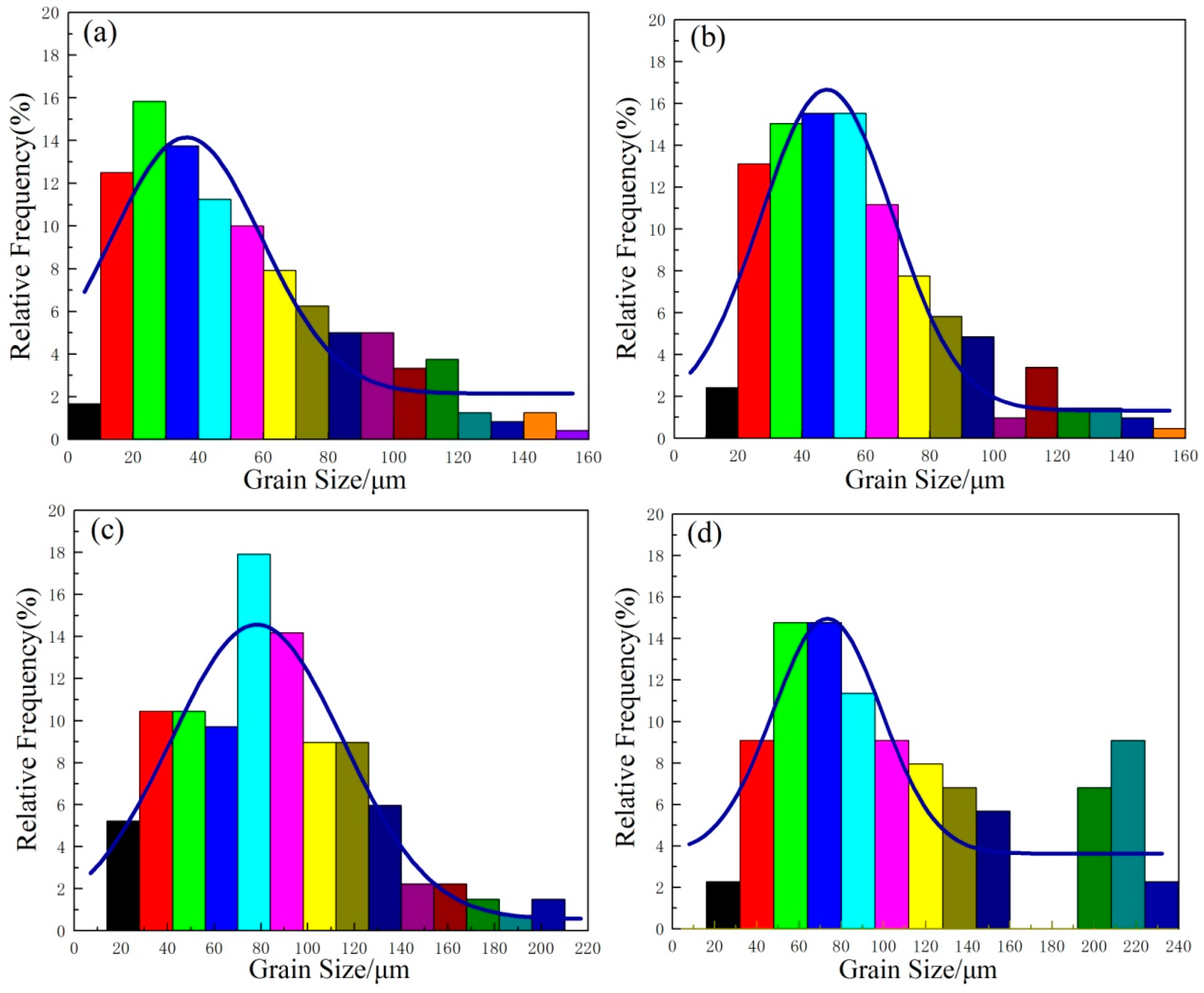
Figure 9 show the microstructure evolution at different solution temperatures and solution times with corresponding austenitic grain-size distribution histograms, respectively. As shown in
Figure 9, the grain size distribution of austenite is close to lognormal distribution, which is consistent with the results presented by Han et al. [
16] and Kurtz et al. [
17]. When the solid solution time is 0.5 h at 1170 °C, the fine austenite grains distribute inhomogeneously as coarse austenite grains and contact each other, as shown in
Figure 8a.
Figure 9a indicates the grain size of austenite is mainly in the range of 20–50 μm. The percentage of AGS smaller than 20 μm is 14.9%. When the specimens were solid solution treated at 1170 °C for an aging time between 0.5 h and 2 h, AGS ranged from 54.8 μm to 58.4 μm. No obvious grain growth was observed in
Figure 8a,b. Those primary carbonitride particles that precipitated along grain boundaries affected the diffusion of iron and carbon atoms, and finally prevented the growth of austenite grain in the heating process [
15,
18]. Compared with the results shown in
Figure 9a, AGS distributes more uniform after SSHT for 2 h, as shown in
Figure 9b. The grain size of austenite shown in
Figure 9c was mostly in the range of 60–80 μm, and the number of austenite grains larger than 50 μm increased with rising solution temperature. When the solid solution time is 3 h at 1230 °C, the bimodality of the histogram presented as a result of further progress in the second recrystallization, presented in
Figure 9d.
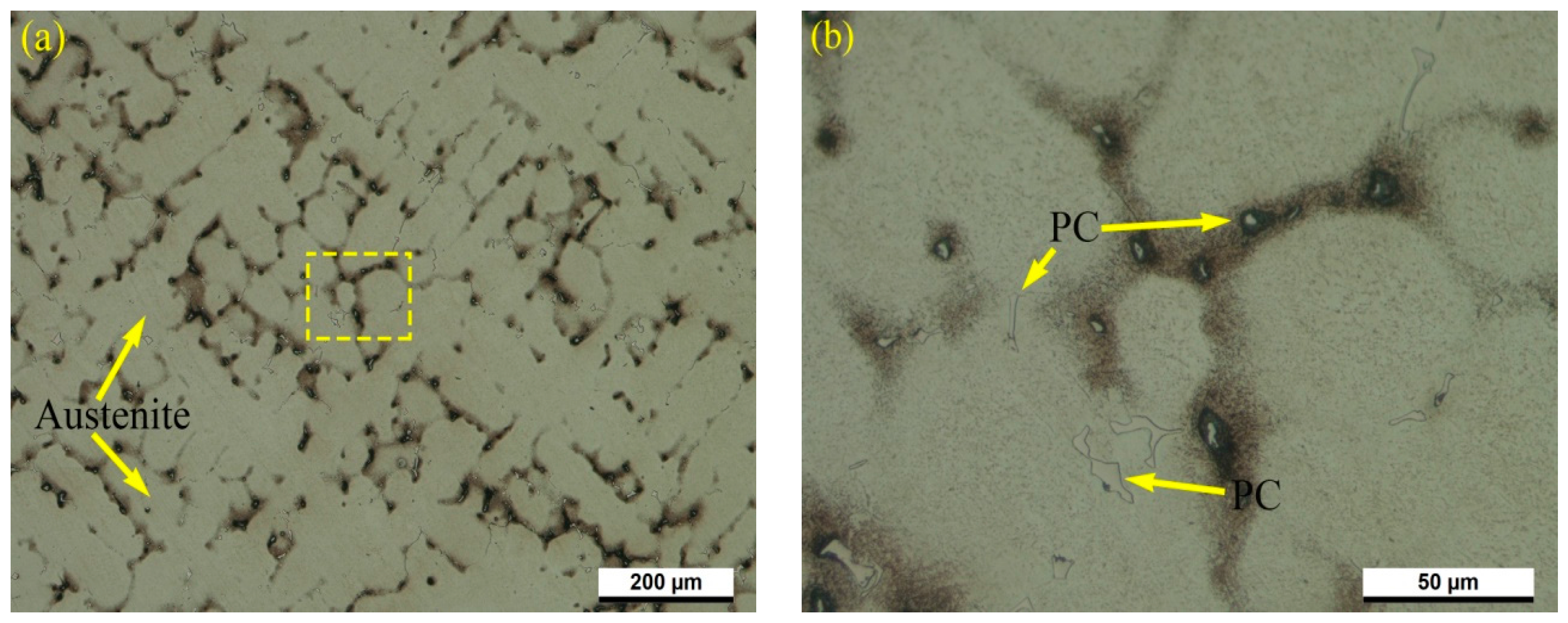
As shown in
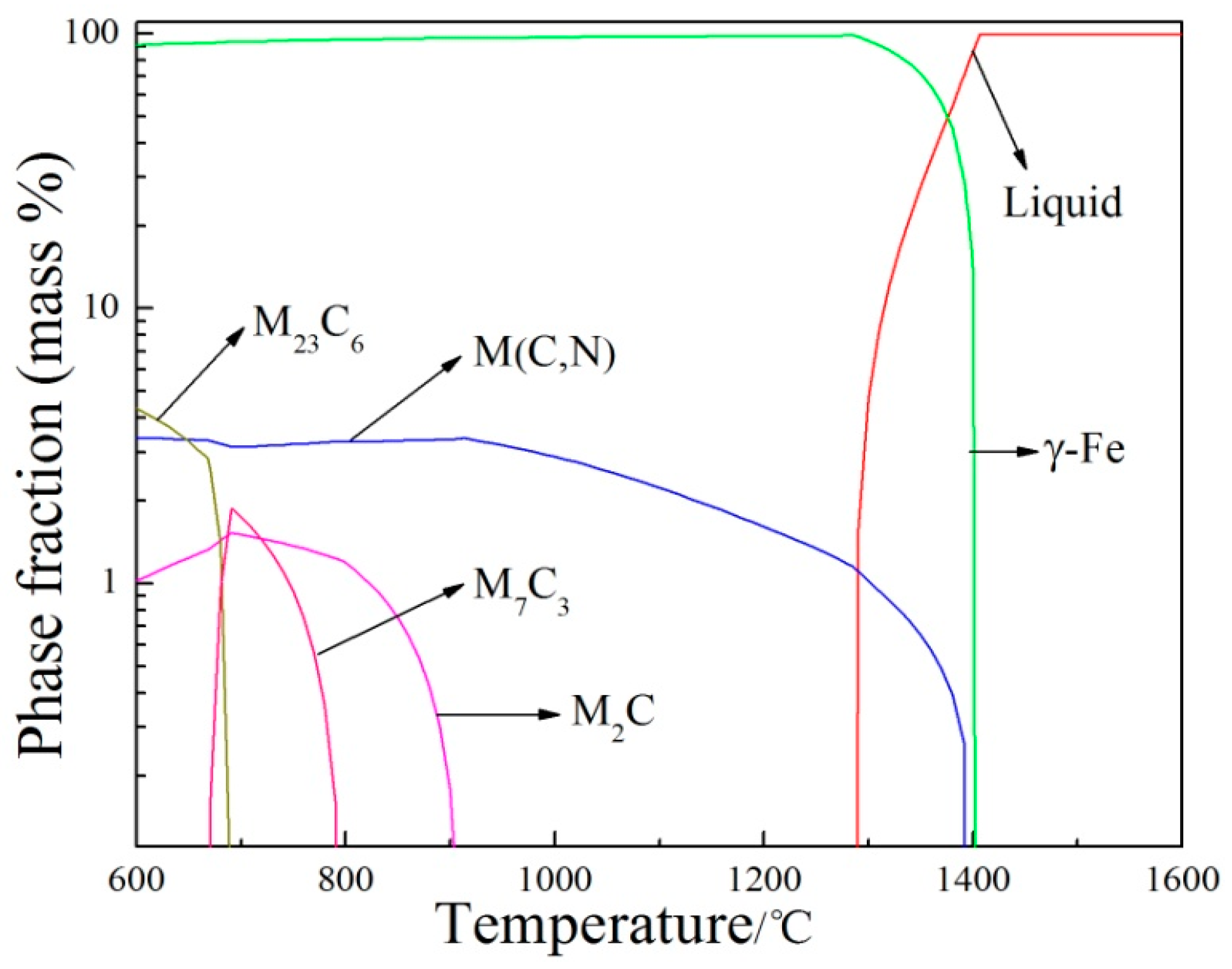
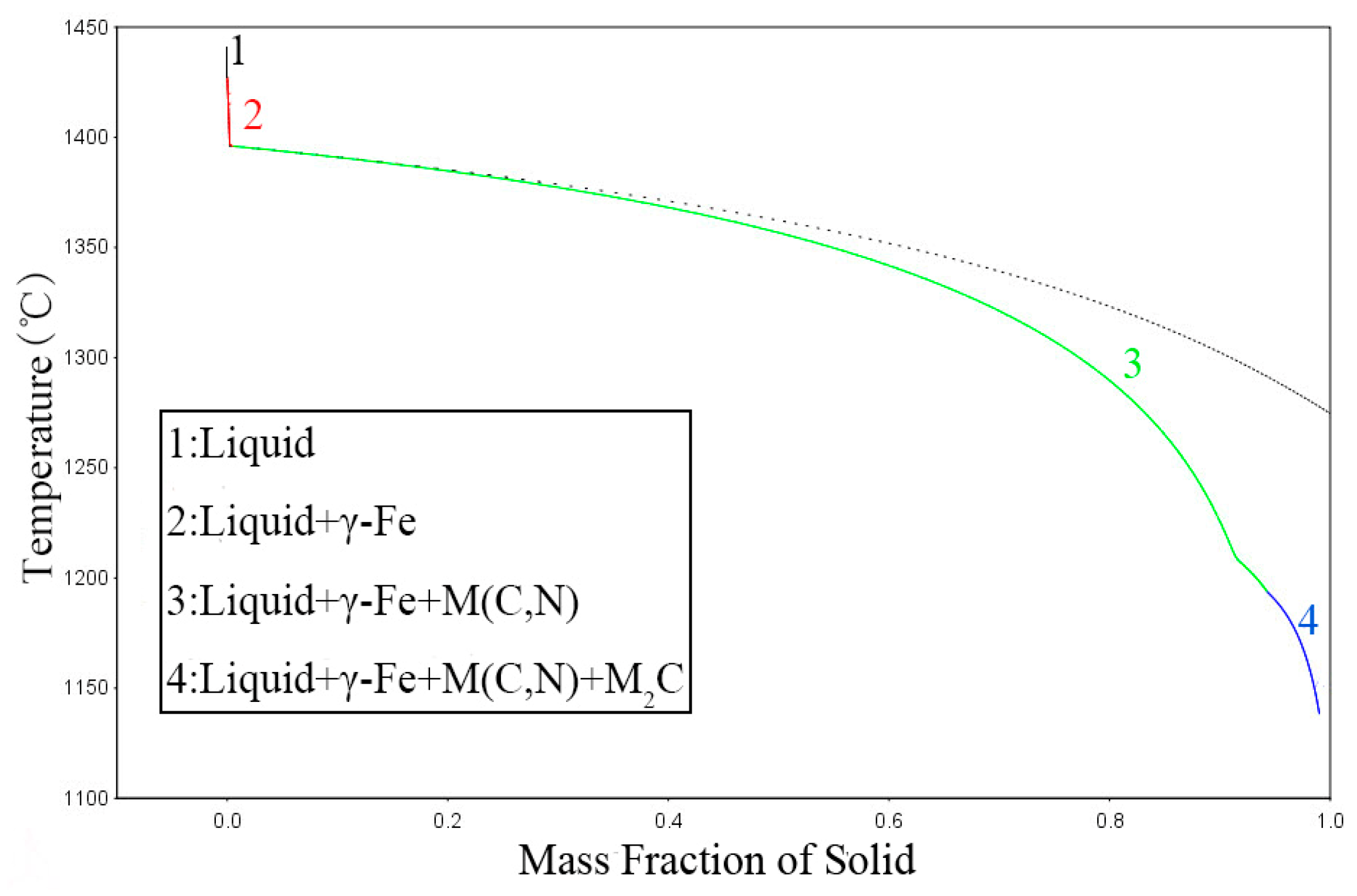
Figure 8a, the precipitates were not completely dissolved at 1170 °C, which is consistent with thermodynamic calculation using Thermo-Calc software. Thermodynamic calculation illustrates that precipitation temperature of the primary V(C,N) reaches up to 1390 °C, as shown in
Table 4. N addition in steel increased the melting point and stability of carbonitrides. In addition, most primary V(C,N) were distributed along the austenite grain boundary and were not significantly influenced by solution heat treatment [
19]. Hence, primary V(C,N) cannot completely dissolve into the matrix when the solution temperature is below 1390 °C. Therefore, it can be concluded that the pinning effect of undissolved V(C,N) [
20] suppressed austenite grain growth with increasing solution time from 0.5 h to 2 h at 1170 °C. Meanwhile, more carbides, carbonitrides, and alloying elements dissolved into the austenite matrix with increasing solid solution time at 1170 °C. Owing to solution strengthening and the second phase strengthening during the process of aging heat treatment, the hardness of steel reached the maximum value at 2 h aging time when solution temperature was at 1170 °C. When aging time exceeded 2 h at 1170 °C, the austenite grain grew rapidly, which led to the decrease of hardness value. When the solution temperature is more than 1170 °C, the AGS grows rapidly, despite a significant amount of undissolved secondary phases. This is attributed to coagulation process during the SSHT process, leading to the growth of large particles at the expense of small ones and the reduction in the amount of precipitates. A small number of large precipitates do not limit grain boundary mobility, and pinning effects disappear [
21]. Grain growth highly depends on the grain boundary migration and the atomic diffusion. Moreover, the dissolution/coarsening of precipitates occurs at higher temperatures [
22,
23]. Furthermore, the solute drag effect of alloying elements is not effective enough at very high temperatures due to their higher frequency of vibration and mobility [
24]. Therefore, the grain growth kinetics is intensified by increasing solid solution temperature. At a very high solution temperature of 1230 °C, the austenite grains coarsened significantly. The coarse austenite grains accelerated the development and growth of fatigue-induced cracks, which will lead to hot work steel failure. After solid solution at 1230 °C for 3 h, grain coarsening became more evident as a result of further progress in the second recrystallization, shown in
Figure 8d and
Figure 9d. Hence, austenitic grain-coarsening speed is accelerated, and undissolved V(C,N) pinning effect was weakened, resulting in the decrease of hardness in a linear trend when the solution temperature exceeds 1200 °C. Hence, the optimal combination of hardness and AGS can be obtained by soaking for 2 h at 1170 °C.
3.3. Effect of Aging Heat Treatment on Mechanical Properties and Microstructure
To remove residual stress caused by SSHT and dispersed small secondary phase particles, high-temperature aging heat treatment was carried out. The aging heat treatment process has a significant effect on comprehensive performance of HMAS-N. According to Grabovskii et al. and Lanskaya’s [
3,
25] reports, two-stage aging instead of single-stage aging can substantially increase impact toughness at the same level of high-temperature strength, which positively affects the crack resistance of the tools and increases their service life. However, there are few literatures on the effect of multiple aging on the microstructure and properties of austenitic hot work die steels. Al–Zn–Mg alloys and some high-temperature alloys such as iron–nickel superalloys are subjected to multistage aging to enhance their comprehensive performance [
26,
27]. To improve the comprehensive performance of HMAS-N, the effects of single-stage aging and two-stage aging on the microstructure and properties of steel were studied.
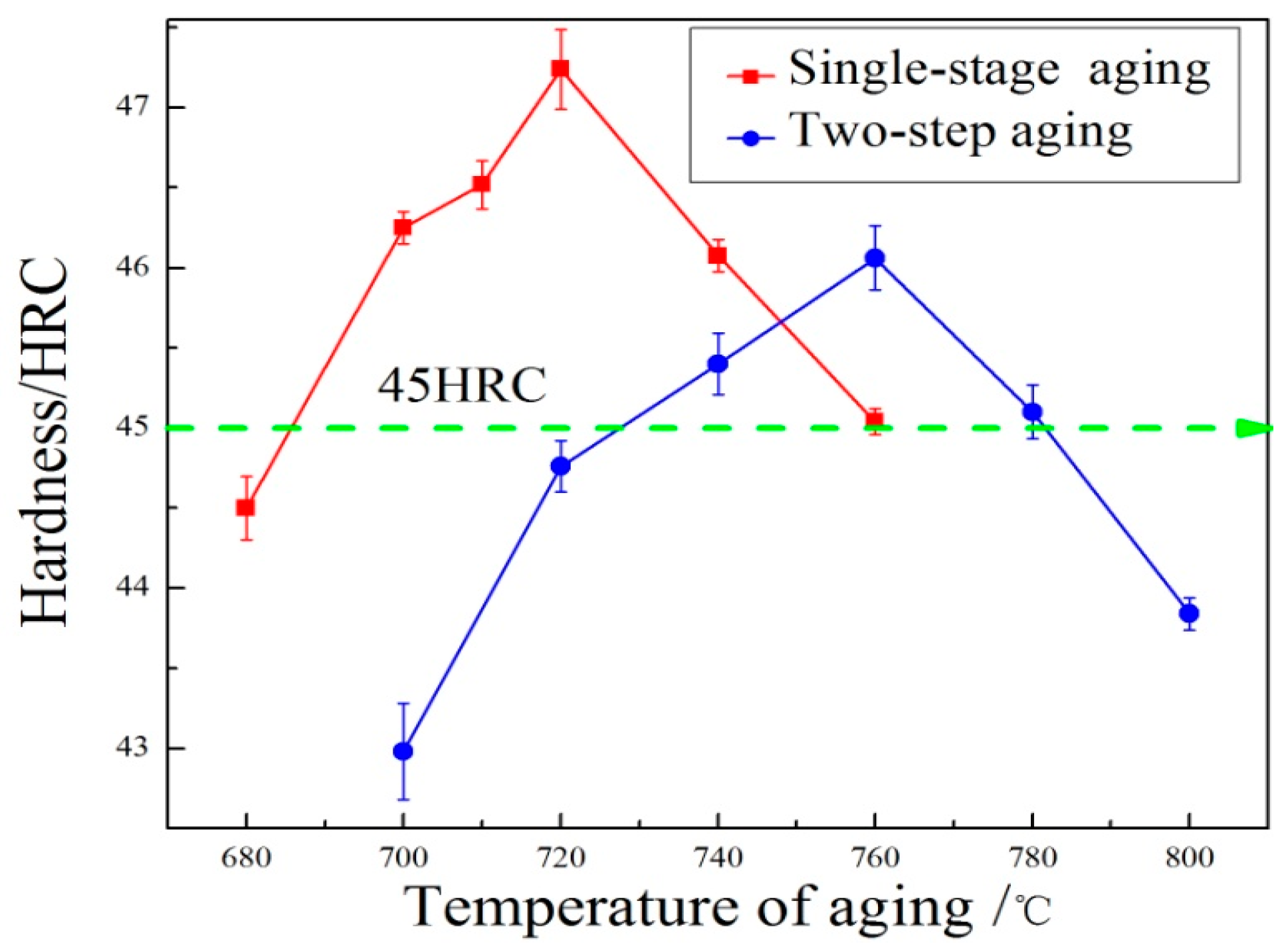
As for single-stage aging, experiments were carried out in a temperature range from 680 °C to 760 °C for 2 h, as shown in
Table 2. The hardness improves gradually with aging temperature increasing from 680 °C to 720 °C, as shown in
Figure 10. When the aging temperature was at 720 °C, significant secondary hardening occurred, and the hardness reached the maximum value of 47.24 HRC. It can be attributed to the enrichment and segregation of precipitate-forming elements at 720 °C, such as V, Mo, Cr, C, and N [
8]. As the aging temperature continued to increase, the hardness decreased to 45.04 HRC at 760 °C. As for the two-stage aging, pre-aging and re-aging heat treatment experiments were carried out, shown in
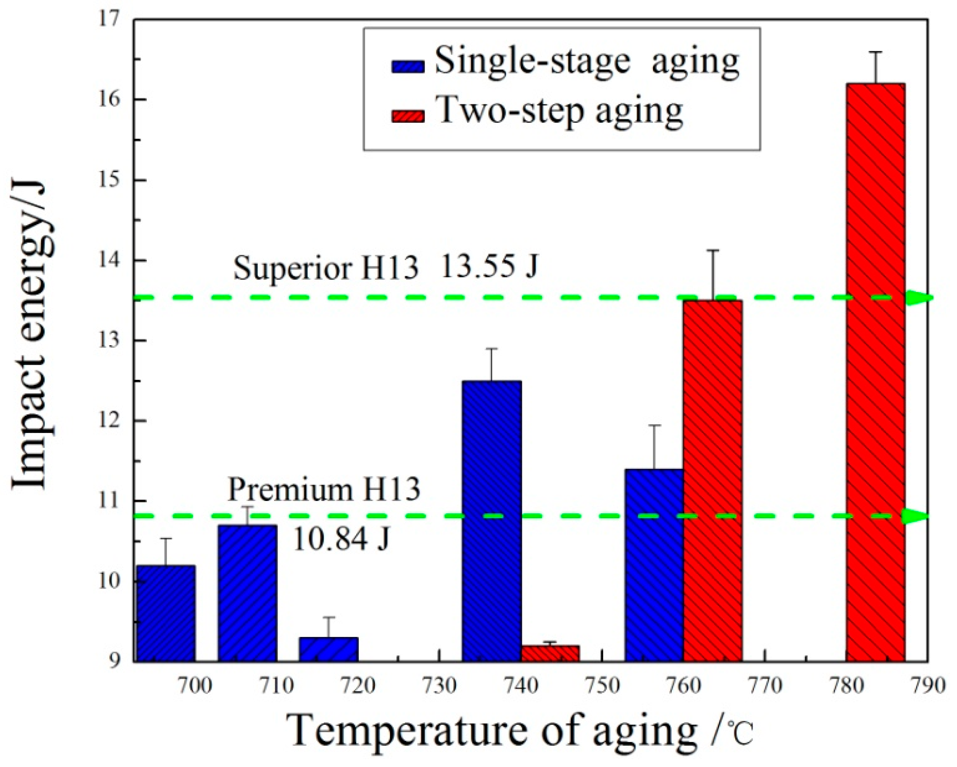
Table 3. The hardness increases with the re-aging temperature increasing from 700 °C to 760 °C. When the two-stage aging temperature was at 760 °C, the hardness reached the peak value of 46.06 HRC. As the re-aging temperature continued to increase, the hardness decreased and dropped to 43.84 HRC at 800 °C. Compared to single-stage aging, the hardness value of two-stage aging is slightly less than single-stage aging at the same aging temperature. In addition, the temperature for maximum hardness delayed. To ensure that the steel has higher hardness and impact toughness to restrain crack initiation and growth in the process of service, the Charpy impact tests were carried out for the specimens with Rockwell hardness values greater than 45 HRC after aging heat treatment. The impact energies after different aging heat treatments are shown in
Figure 11. For single-aging at 720 °C, the hardness value reached the maximum value of 47.24 HRC, whereas the impact energy reached the minimum value at 9.2 J. The impact energy reached the maximum value of 12.5 J and the corresponding hardness value was 46.05 HRC at 740 °C. For two-stage aging, the impact energy gradually increased and reached the maximum value of 16.2 J at 780 °C with increasing temperature from 740 °C to 780 °C. As for two-stage aging heat treatment, impact energy greatly improved despite the hardness decreasing by 1–2 HRC compared with single-stage aging.
The maximum impact energy value of 16.2 J is not only higher than premium H13 (10.84 J), but also almost exceeds superior H13 (13.55 J) [
28]. The newly prepared HMAS-N, in terms of the toughness, is considerably outstanding when taking H13 mechanical properties into consideration. Compared with the maximum impact energy of single-stage aging, two-stage aging impact energy increased 29.6%. Despite the lowest hardness value of 45.1 HRC at 780 °C re-aging temperature, it still meets the service requirements of hot work steel. Hence, in order to improve the comprehensive performance and service life, the optimal aging process is re-aging at 780 °C.
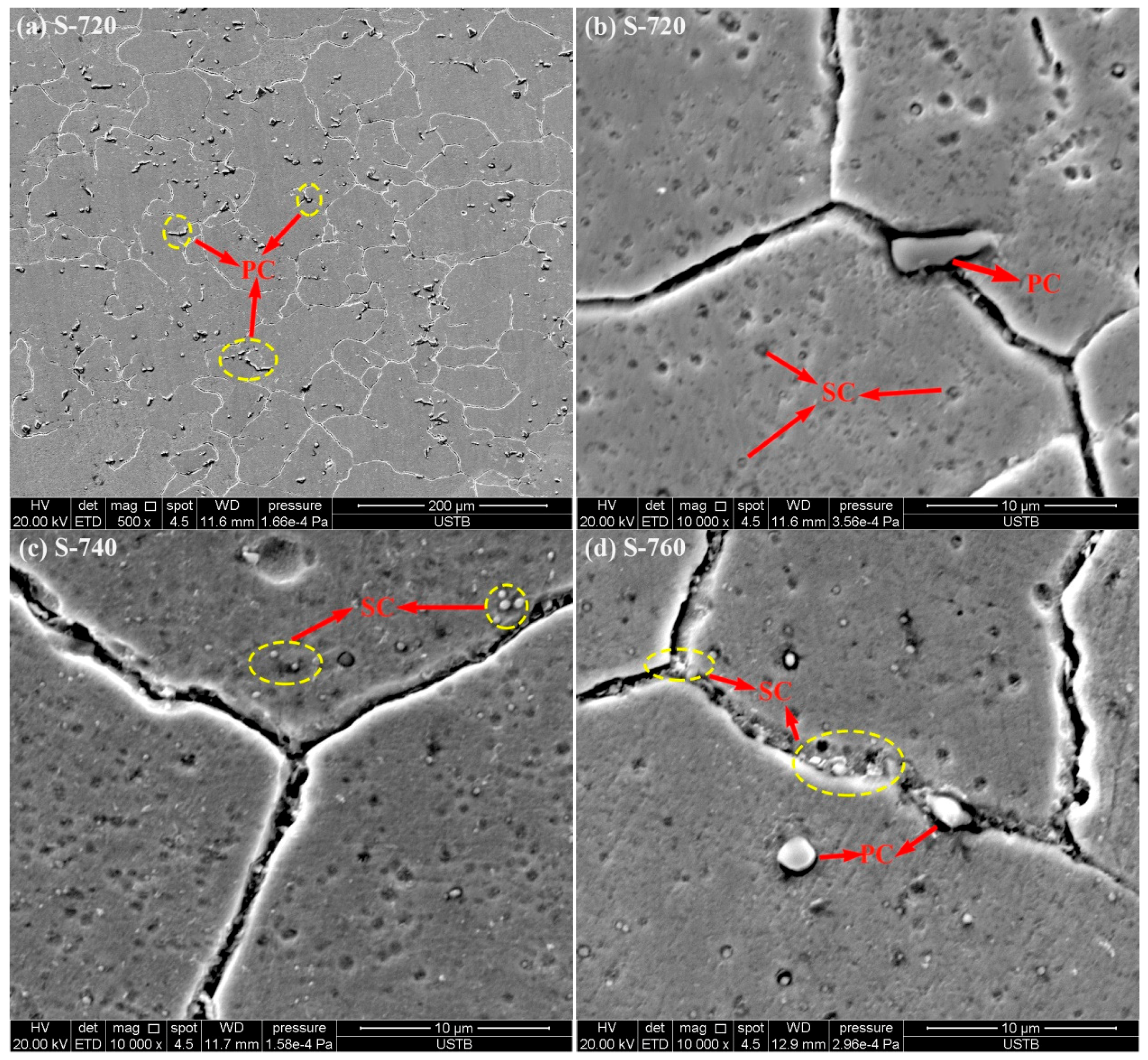
It is well known that structure and fractograph of a specimen are related to the mechanisms involved in the fracture process. The microstructure determines the performance of the steel.
Figure 12a is a SEM micrograph of specimen S-720 at low magnification. It can be seen that there are massive, undissolved primary precipitates.
Figure 12b–d are the scanning electron micrographs of specimens S-720, S-740, and S-760 at high magnification, respectively. When the aging temperature increased from 720 °C to 740 °C, the number of fine dispersed secondary carbonitrides increased, as shown in
Figure 12b,c. As the aging temperature increased to 760 °C, the number of secondary carbonitrides decreased, but the secondary carbonitrides appeared to be aggregated, and the grain boundary was widened, as shown in
Figure 12d. This is attributed to growth of large particles at the expense of small ones, resulting in the reduction in the total number of particles. Precipitation of carbides along the grain boundary will result in deterioration of toughness, which can be attributed to the decrease of grain boundary cohesion.
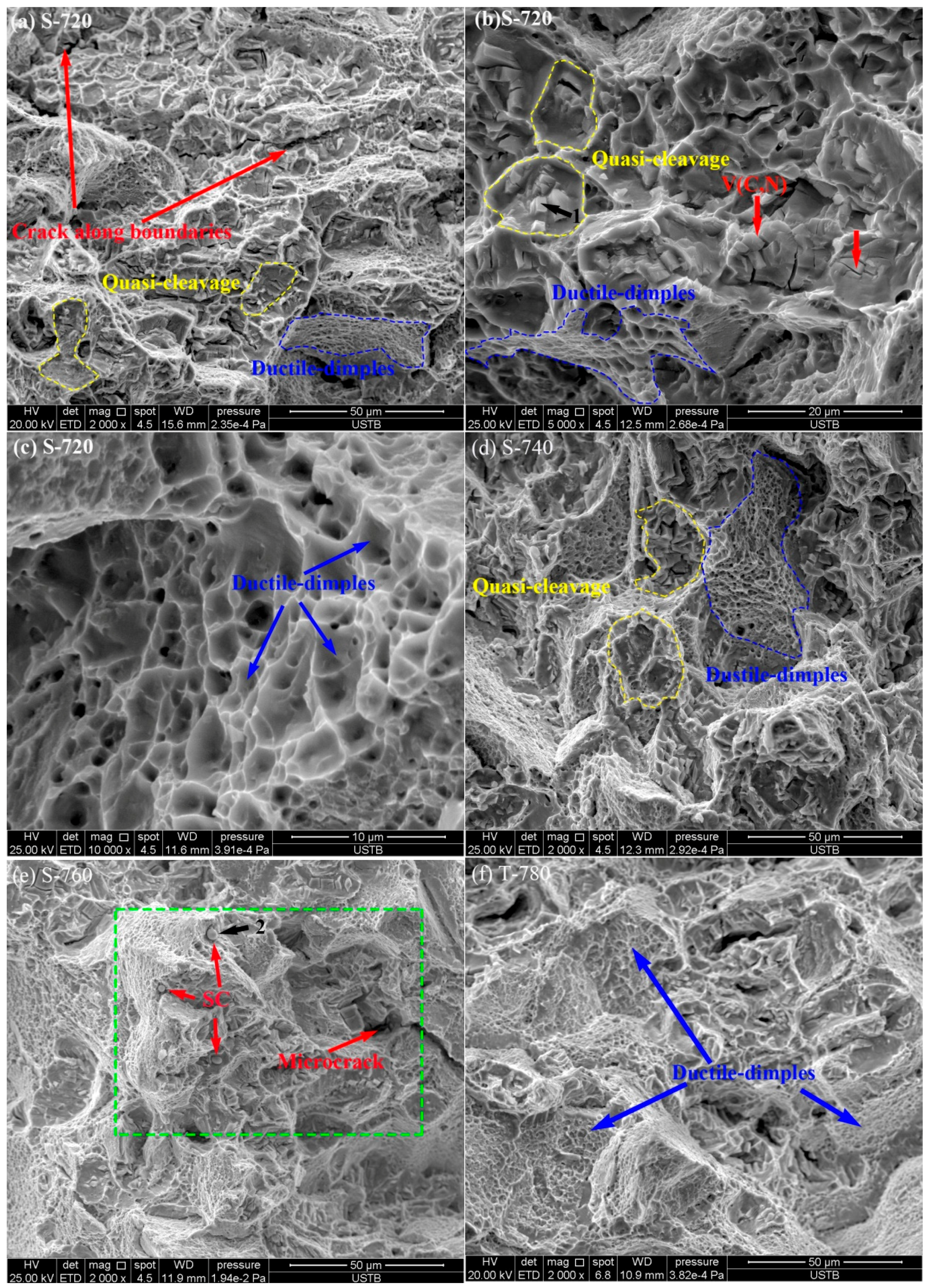
The SEM fractograph of specimens after the Charpy test for a fixed solid solution temperature (1170 °C) and various aging processes are shown in
Figure 13a–f. Both quasi-cleavage facets and ductile dimples were observed, which indicated the mixed mechanism of fracture. The specimen S-720 showed mainly brittle-fractured surface zones characterized by transgranular quasi-cleavage and intergranular fracture (
Figure 13a). It can be noticed that quasi-cleavage fracture facets encircled by ridges are much smaller than the austenite grain (58.4 μm), and this kind of morphology forms when a crack propagates along the primary precipitates. The size of intergranular fracture grains (~60 μm) was similar to the size of austenite grains (58.4 μm). This implies that intergranular fracture along the boundaries of austenite grains operated partially for specimen S-720. As shown in
Figure 13b, quasi-cleavage facets show massive primary precipitates, which is consistent with the observation in
Figure 11a. It indicated that quasi-cleavage nucleated along the precipitates. Some portions of the fracture surface exhibited ductile-fractured surface with fine dimples (
Figure 13c). The dimple percentage increases with increasing aging temperature (from 720 °C to 760 °C) for single-stage aging treatment. The specimens S-740 and S-760 showed mainly ductile-fractured areas with fines dimples and some quasi-cleavage features (
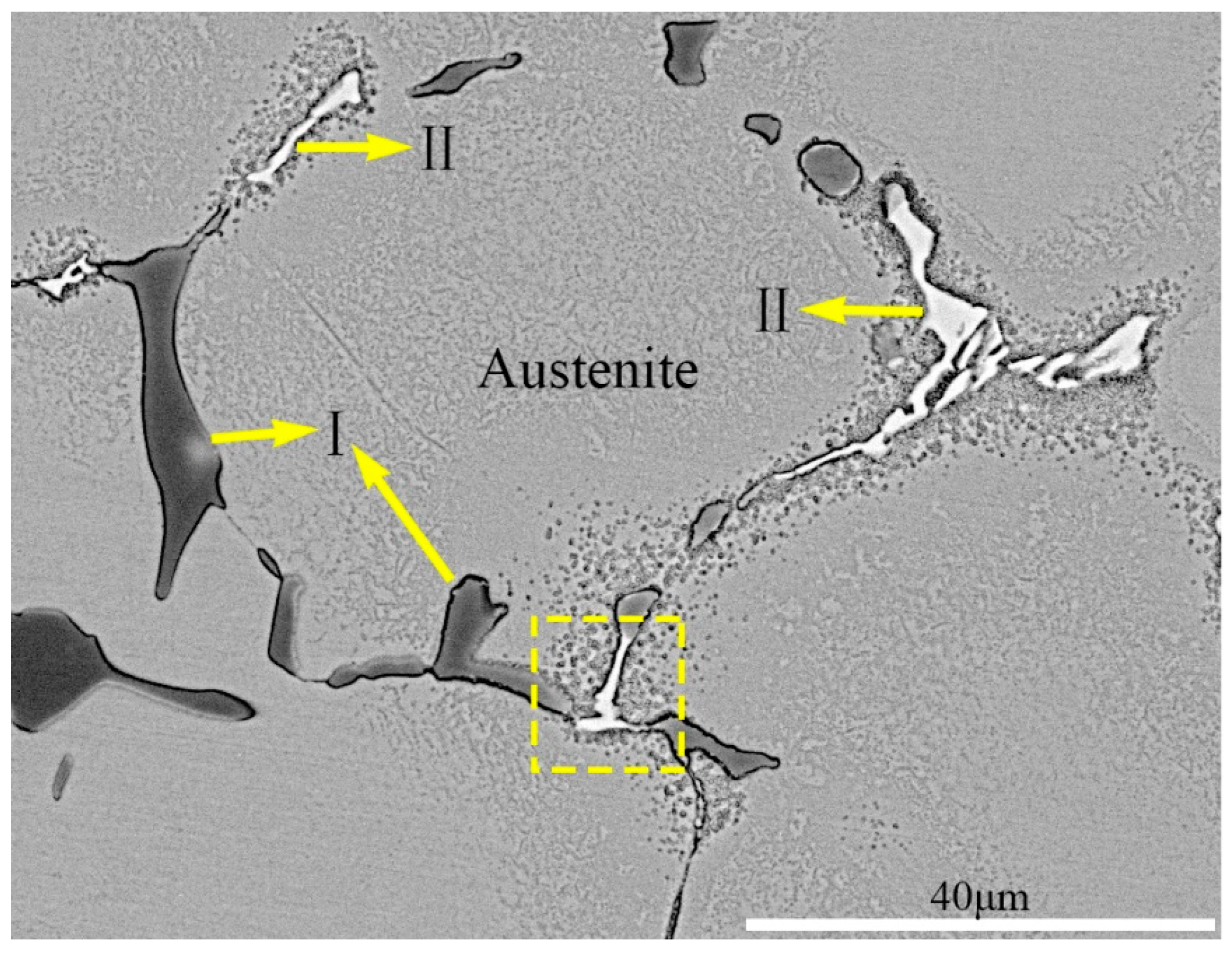
Figure 13d,e). It is clear that the fracture surface of specimen S-760 contained microcracks and some spherical secondary precipitates precipitated from the aging process, as shown in
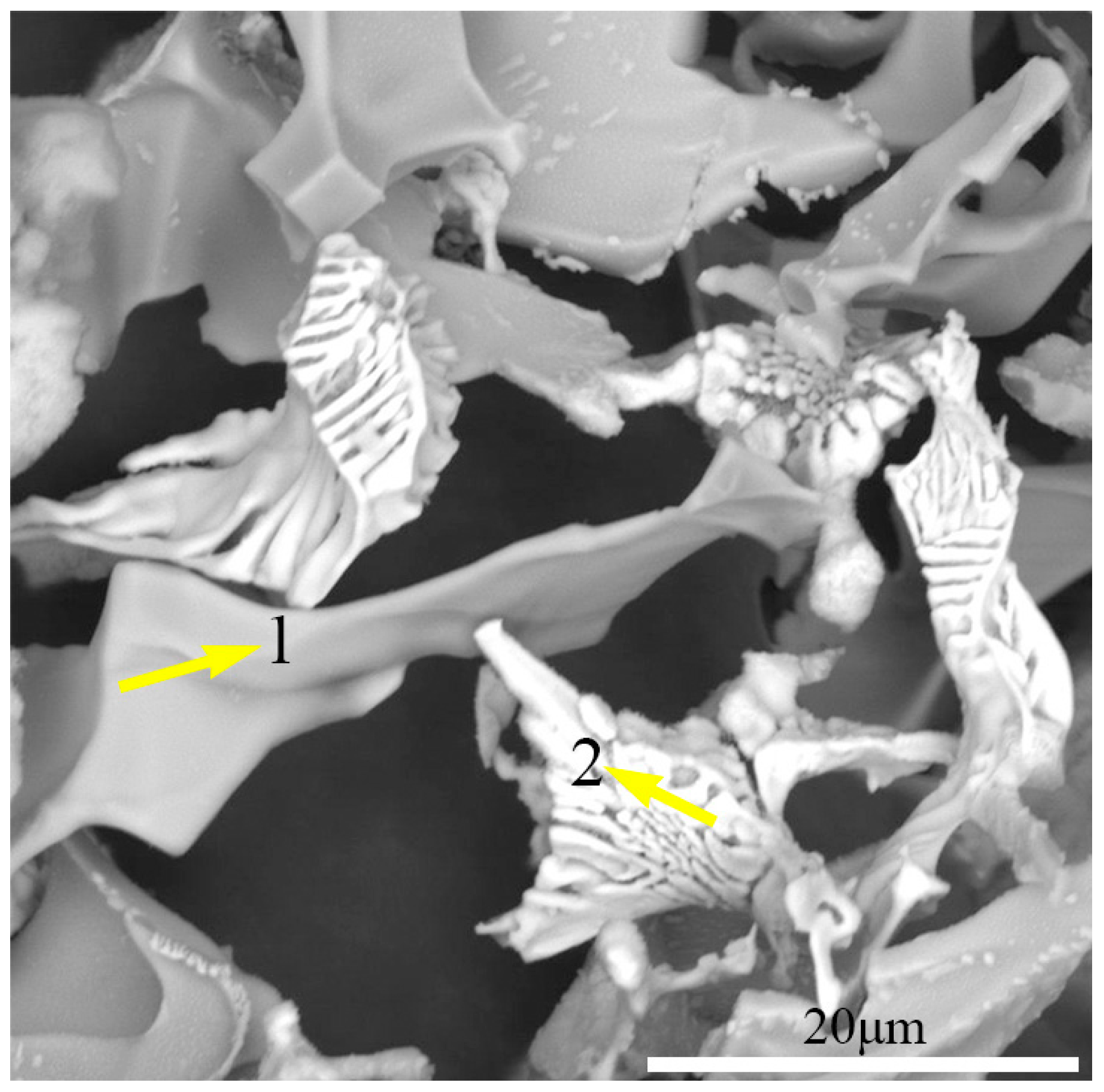
Figure 13e. The EDS results of the precipitates shown in
Figure 13b,e are presented in
Table 6.
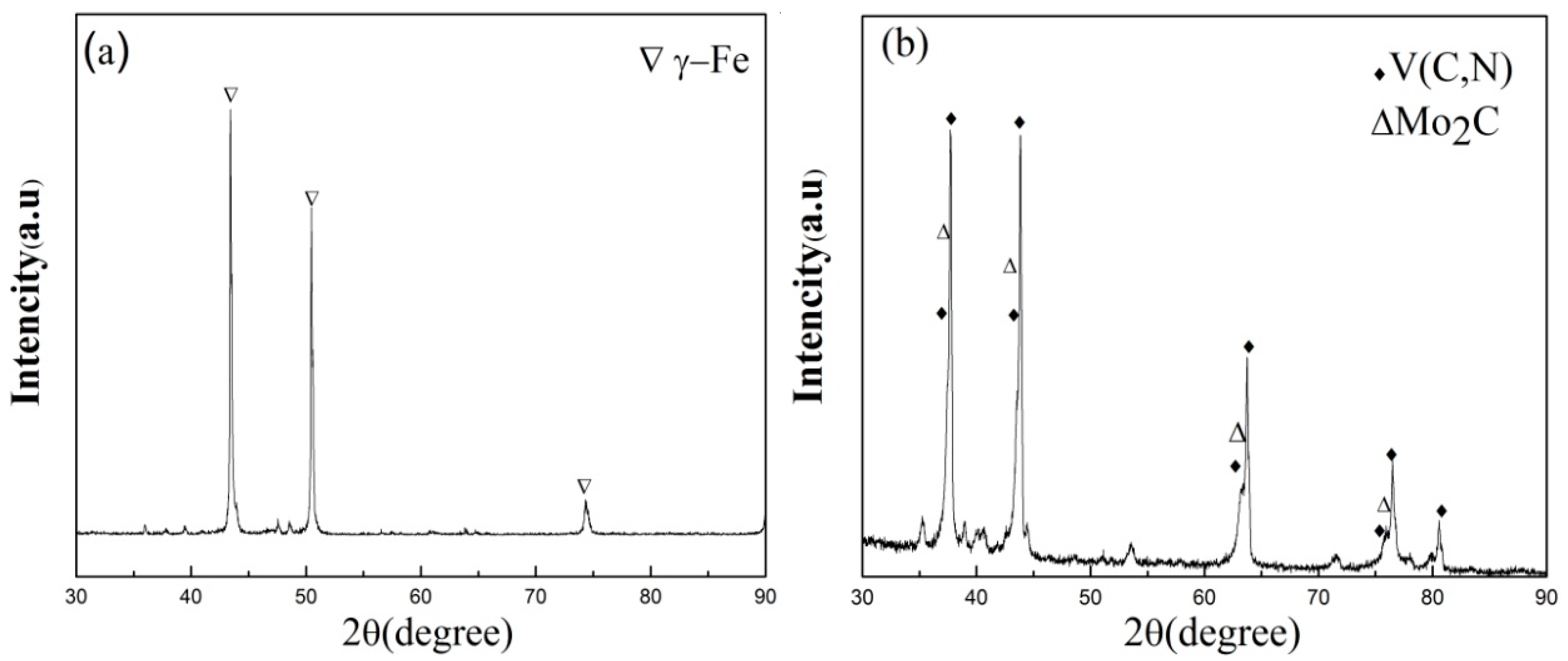
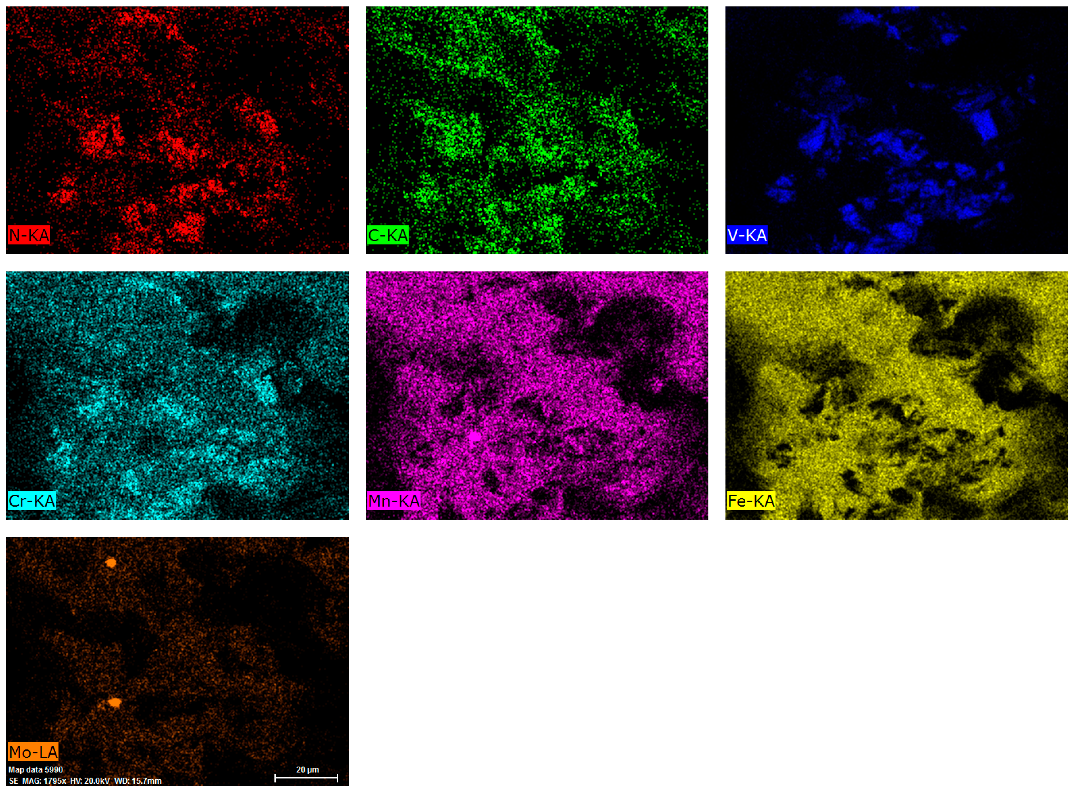
Figure 14 shows fractograph EDS element distribution mappings of specimen S-760.
Figure 14 and the EDS results of point 1, shown in
Figure 13b, indicate that elements N, V, C were enriched in the same area, confirming that undissolved coarse primary carbonitrides are V(C,N), which also contains a small amount of Cr.
Figure 14 and the EDS results of point 2, shown in
Figure 13e, indicate that spherical secondary carbides are Mo-rich carbides. Specimen T-780 presented more ductile dimples and fewer quasi-cleavage facets (
Figure 13f).
The undissolved primary precipitates, austenite grain size, strength of the matrix, secondary precipitates, and the strength of grain boundary have great effects on the impact energy, while aging heat treatment has little effect on primary precipitates and austenite grain size. For specimen S-720, the massive undissolved primary V(C,N) had a higher hardness value (47.2 HRC) and is not easy to deform, which is responsible for embrittlement for the lower impact energy (9.3 J). A lower binding force among precipitates and steel matrix resulted from the existence of primary and secondary precipitates. It is much easier to generate cracks at the regions where primary V(C,N) are enriched.
With increasing aging temperature from 720 °C to 740 °C for single-stage aging, the amount of secondary precipitates increased, which meant the interstitial atoms dissolved in the matrix precipitated and the degree of supersaturation decreased, resulting in the softening of the steel matrix [
29]. The increasing number of secondary precipitates has a negative effect on impact energy. The softer the base metal, the larger the plastic district around the crack tip when the stress concentration is high enough and plastic deformation occurs. A larger plastic district will result in greater crack propagation and larger impact energy [
30]. For specimen S-720 and S-740, the base metal plays the main role on impact energy compared to the negative effect of secondary precipitates. Hence, impact energy increased from 9.3 J to 12.5 J with increasing temperature, from 720 °C to 740 °C, for single-stage aging temperature. When increasing temperature to 760 °C for the single-stage aging, the amount of secondary precipitates increases and the coarsening of the austenite grain boundary has a major effect on the impact energy, which led to impact energy decreasing from 12.5 J to 11.4 J.
For two-stage aging, the low-temperature pre-aging of the two-stage aging process is equivalent to the nucleation stage, and the high-temperature aging is the stabilization stage [
26]. The first stage in aging of the alloy is to promote the formation of the GP (Guinier-Preston) zone, and then to obtain a large number of dispersed GP areas, and to make the GP areas extend to a certain scale without dissolution in the second stage of aging. In the second high-temperature aging process, the aging precipitation sequence of the alloy changes from GP zone to secondary precipitates, and the alloy enters the aging stage. This improves the working capacity of tools for hot deformation. The two-stage aging may be more conducive to distributed homogeneous precipitation of secondary precipitates and reducing growth of secondary precipitates, which will weaken the reduction of the impact energy compared to single-stage aging. As a result, the impact energy increases from 9.2 J to 16.2 J with a slight decrease of the strength when increasing the re-aging temperature from 740 °C to 780 °C.


