Article

Influence of Heat Treatment on the Workability of Modified 9Cr-2W Steel with Higher B Content

1
Gwangju center, Korea Basic Science Institute, 77 Yongbong-ro, Buk-gu, Gwangju 61186, Korea
2
Innovative Fuel Technology Development Division, KAERI, 989-111 Daedeok-daero, Yuseong-gu, Daejeon 34057, Korea
3
Department of Materials Engineering, Hanyang University, 55, Hanyangdaehak-ro, Sangnok-gu, Ansan-si 15588, Korea
*
Author to whom correspondence should be addressed.
Metals 2019, 9(8), 904; https://doi.org/10.3390/met9080904
Submission received: 15 July 2019 / Revised: 16 August 2019 / Accepted: 16 August 2019 / Published: 18 August 2019
(This article belongs to the Special Issue Forming Processes of Modern Metallic Materials)

Abstract

:
In this study, the effect of heat treatment on the fracture behavior of alloy B steel with boron (B) contents as high as 130 ppm was investigated. The Alloy B are derived from Gr.92 steel with outstanding creep characteristics. The amounts of minor alloying elements such as B, N, Nb, Ta, and C were optimized to achieve better mechanical properties at high temperatures. Hence, workability of the alloy B and Gr.92 were compared. An increase in the B content affected the phase transformation temperature and texture of the steel. The development of the {111}<uvw> components in γ-fibers depended on the austenite fraction of the steel after the phase transformation. An increase in the B content of the steel increased its α-to-γ phase transformation temperature, thus preventing the occurrence of sufficient transformation under the normalizing condition. Cracks occurred at the point of the elastic-to-plastic deformation transition in the normal direction during the rolling process, thereby resulting in failure. Therefore, it is necessary to avoid intermediate heat treatment conditions, in which γ-fibers do not fully develop, i.e., to avoid an imperfect normalization.

1. Introduction

Owing to its low-cost raw materials and excellent base load capacity, nuclear power generation plays a key role in meeting the energy demands of Korea. However, the large-scale commercialization of nuclear power is limited because of the large amounts of nuclear fuel spent after the operation. In order to overcome this limitation, it is imperative to develop an innovative nuclear power plant, which can contribute to sustainable development and environmental protection while producing sufficient energy to meet the increasing demands [1,2].
Sodium cooled fast reactors (SFRs) have gained immense attention in this context owing to their economic efficiency, stability, nuclear non-proliferation, and low emission of spent nuclear fuel. These reactors operate at temperatures much higher than the operating temperatures of light water reactors and exhibit high thermal efficiency [3,4,5,6,7]. The nuclear fuel cladding tube, which transfers the fission energy and comprises the nuclear fuel rod and fissile material, is the main component of these reactors. Hence, the development of efficient fuel cladding tubes is essential as they are crucial for the safety of nuclear reactors.
Ferritic-martensitic (FM) steels are considered to be promising candidates for fuel cladding and duct materials for SFRs owing to their high thermal conductivities, low expansion coefficients, and superior irradiation swelling compared to that of austenitic steels [8,9,10]. However, the creep rupture strength of FM steels abruptly decreases during the long-term creep exposure at high temperatures [11]. Advanced FM steel alloys are derived from Gr.92 steel. The amounts of minor alloying elements such as B, N, Nb, Ta, and C were optimized to achieve better mechanical properties at high temperatures [10]. In our previous study, we prepared 36 model alloy ingots of 9Cr-2W steel by adjusting their B and N contents, and the two model alloy ingots with the best creep characteristics were used to design cladding tubes [12]. Research on the material property and the manufacturing technology of these alloys will considerably contribute to extend their application as nuclear reactor parts with excellent creep characteristics and the ability to withstand high temperatures.
The optimum heat treatment conditions and amount of cold work depend on the manufacturing process parameters such as the cold rolling rate and normalizing and tempering heat treatment temperature and time [8]. However, when an alloy B steel plate with a B content as high as 130 ppm is rolled, fracture occurs only when it is subjected to tempering after the normalization. In addition, similar phenomena occur during the cold drawing process under the same conditions. Fracture during the manufacturing process reduces the yield of alloy B steels, resulting in a low productivity.
In this study, the causes of fracture during the manufacturing process of alloy B steels with low production yield were investigated in order to develop a novel manufacturing process for alloy B steels with high formability. The specimens of the rolled alloy B and Gr.92 steels subjected to different intermediate heat-treatment conditions were observed using an optical microscope (OM), a stereoscope, nano-secondary ion mass spectrometry (Nano-SIMS), and electron backscatter diffraction (EBSD). In addition, the mechanical properties of the rolled specimens along the orientation direction were evaluated by carrying out their compression tests.

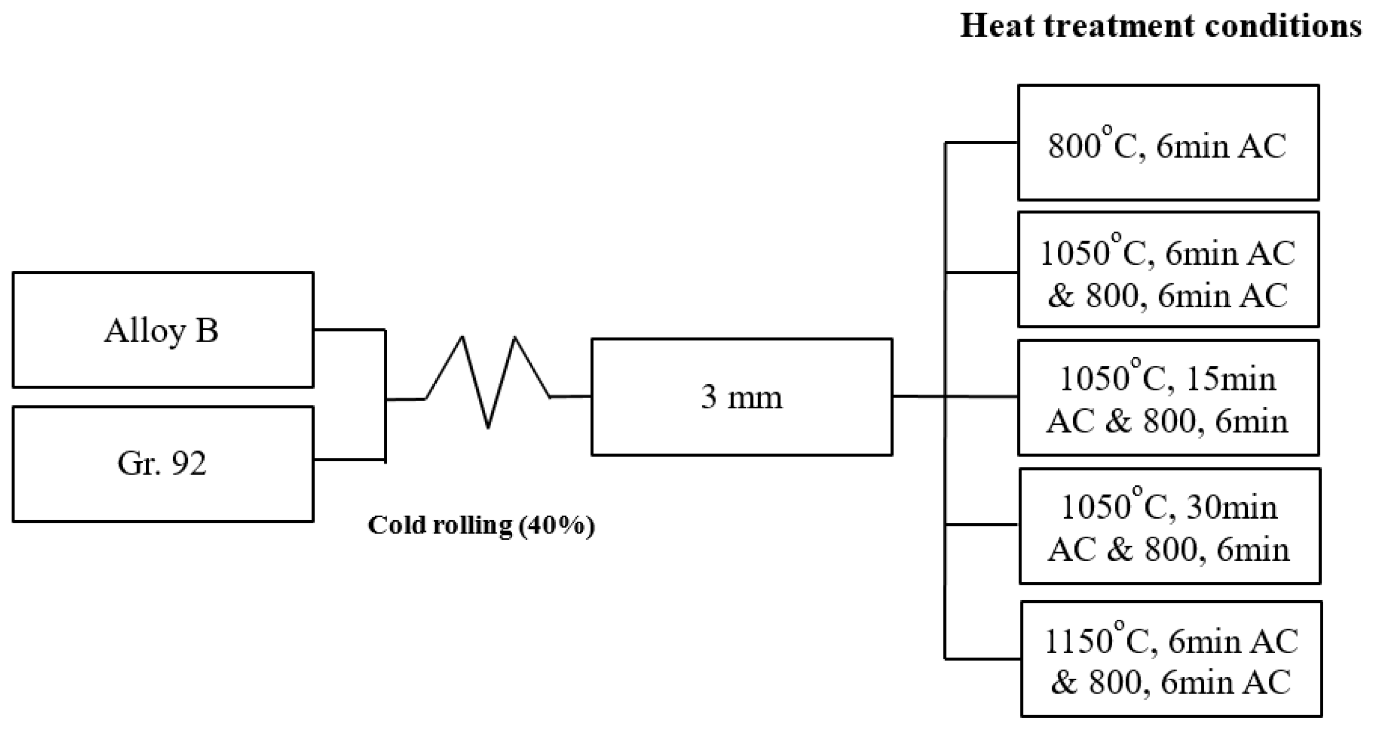
2. Materials and Methods

2.1. Materials

The chemical compositions of the two different kinds of 9Cr-2W steel, designated alloy B and Gr.92, are shown in Table 1. In order to investigate the effect the heat treatment conditions on the formability of alloy B steel, plate specimens were manufactured as follows. Ingots were prepared using a vacuum induction melting process and were fabricated into round bars, which were subjected to hot forging. The round bars had an outer diameter of 100 mm. The hot-forged specimens were normalized at 1050 °C for 6 min, followed by air cooling (AC) at 298 K. Tempering of the normalized specimens was carried out at 800 °C for 6 min, followed by AC. The reference material, Gr.92 with an outer diameter of 200 mm, was purchased and tested. Gr.92 was normalized at 1040 °C for 5 h, followed by AC. Tempering of the normalized specimens was carried out at 760 °C for 8 h, followed by AC. The alloy B and Gr.92 specimens were subjected to the same initial heat treatment and normalizing and tempering conditions. Both the steel specimens had an outer diameter of 100 mm and a thickness of 5 mm.
Cold rolling was performed at the same reduction ratio as the cold drawing process in which fracture occurred. The specimens were rolled to a thickness of 3 mm (from 5 mm), showing a reduction ratio of 40%. The distance between rolling rolls was fixed at 3 mm, and rolling was performed until the thickness of the specimen became 3 mm.
The rolled specimens were heat-treated. The tempering treatment of the rolled specimens was carried out at 800 °C for 6 min, followed by AC. The specimens were normalized at 1050 °C for 6, 15, and 30 min, and 1150 °C for 6 min, followed by AC and were tempered at 800 °C for 6 min, followed by AC. A schematic of the experimental procedure is shown in Figure 1.

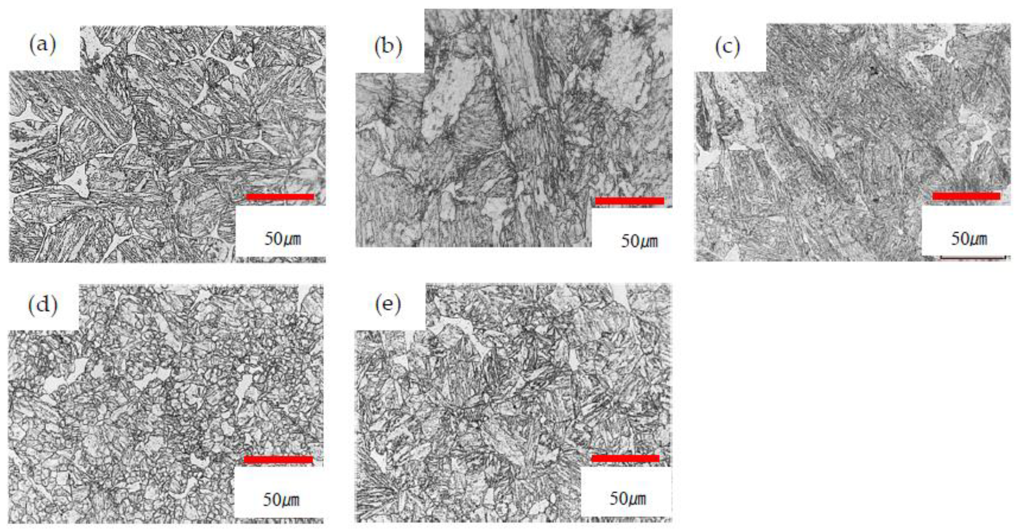
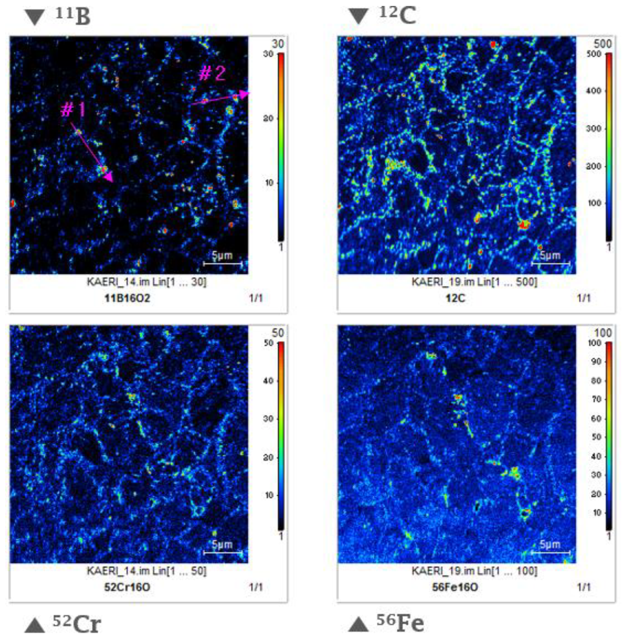
2.2. Observation of Microstructure

The microstructures of the heat-treated alloy B and Gr.92 specimens were investigated using OM and EBSD. The specimens for the microstructural observations were grinded, polished (using a diamond suspension of up to 0.25 µm, and etched (95 mL water + 3 mL nitric acid + 2 mL fluoric acid). The microstructures of the heat-treated specimens were examined by carrying out their EBSD analyses after a metallographic sample preparation step. The EBSD samples required additional one-hour polishing with a 0.04 µm colloidal silica suspension. The EBSD patterns of the specimens were obtained using a Su5000 (Hitachi High Technology, Omuta-shi, Fukuoka, Japan) instrument equipped with a Hikari detector operating with EDAX-TSL OIM DATA collection software (AMETEK Inc., Berwyn, PA, USA). The crystallographic textures of the specimens formed during the various heat treatment processes were recorded. The orientation distribution functions (ODFs) ƒ(g) of the specimens were calculated using the harmonic series expansion method based on Bunge (l = 22) from their incomplete pole figures {110}, {200}, and {211} [13,14]. The orientation g was expressed in the form of a triple Euler angle (φ1, Φ, φ2). All the ODF calculations were carried out assuming that the samples showed a triclinic symmetry, as given by the rolling direction (RD), transverse direction (TD), and normal direction (ND) of a plate such that 0° ≤ {φ1, Φ, φ2} ≤ 90°. Subsequently, secondary ion mass spectrometry (SIMS) imaging with a Nano-SIMS (CAMECA, Gennevilliers, Hauts-de-Seine, France) device was used to observe boron segregation at the grain boundaries. The Nano-SIMS specimens were prepared by a procedure identical to the aforementioned method and were analyzed. Nano-SIMS measurements with statistical errors of less than 0.2% were obtained by using a CS+ gun beam with a diameter of 80 nm and impact energy corresponding to 16 keV and 0.35 pA. Prior to obtaining the distribution maps, the concentration depth profiles of 11B+, 12C, 52Cr+, and 56Fe+ were determined by Nano-SIMS in an area of 10 × 10 μm2. 11B16O2, 12C, 52Cr16O, and 56Fe16O ions were detected and images of boron, carbon, chromium, and iron were obtained [15]. The analysis was performed at the Busan center of the Korea Basic Science Institute (KBSI).

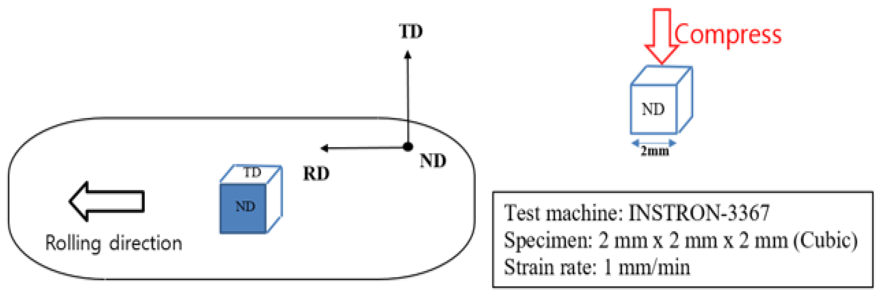
2.3. Compression Test

The applicability of the compression test as a general method for evaluating the cold workability of steel has been investigated [16,17,18]. Compression tests were carried out at 298 K and the strain rate of 1 mm/min using an INSTRON-3367 (INSTRON, Norwood, MA, USA) system to evaluate the mechanical properties and workability of the alloy B and Gr.92 specimens subjected to the different heat treatment processes. The sampling and compression test procedure of the specimens are shown in Figure 2. The specimens were obtained by rolling a plate in three different directions, i.e., RD, TD, and ND. These specimens were cubes with the dimensions of 2 mm × 2 mm × 2 mm and had a smooth surface. The actual displacement and load of the specimens were recorded continuously during the compression test. In addition, the occurrence of cracks in the specimens was monitored.

3. Results

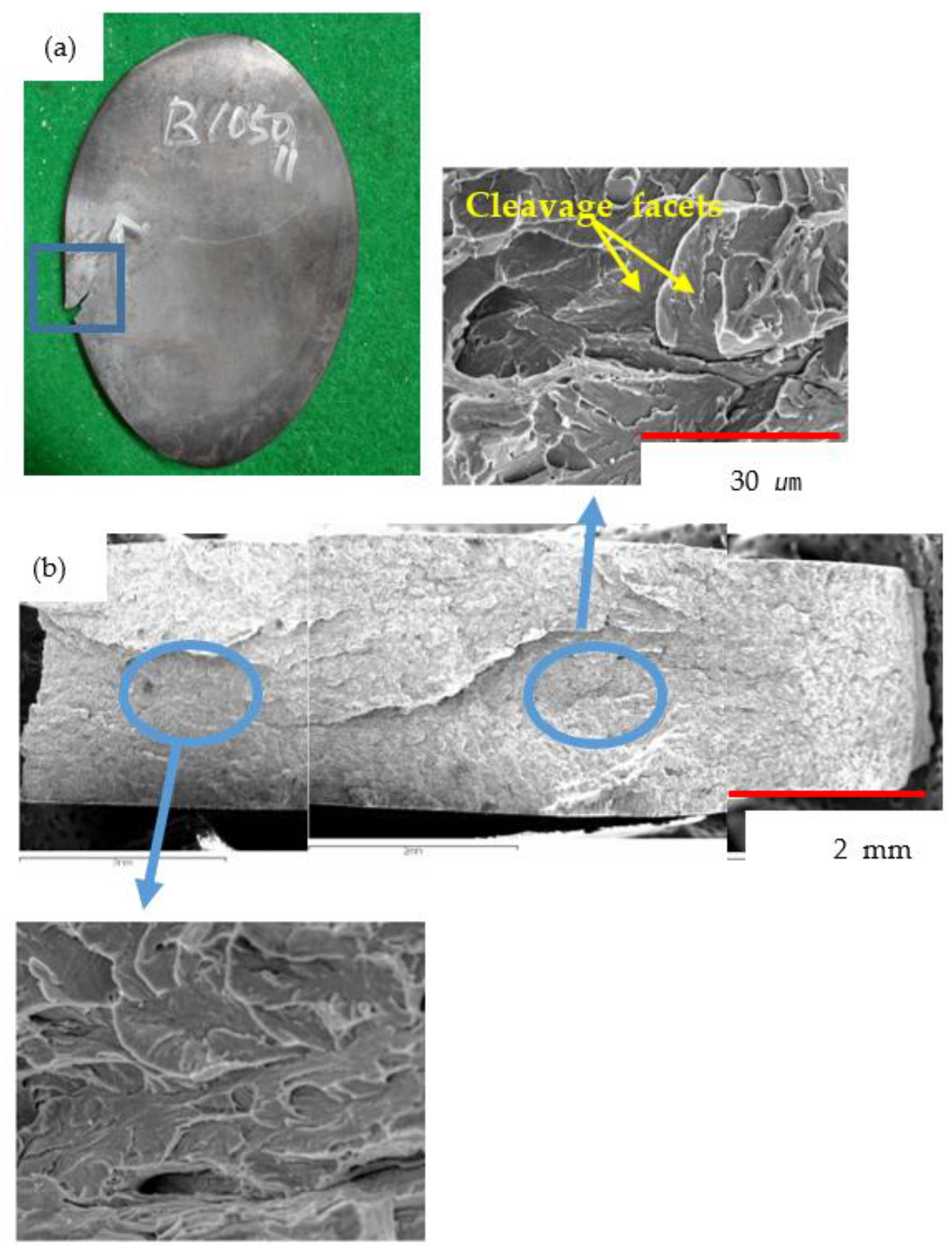
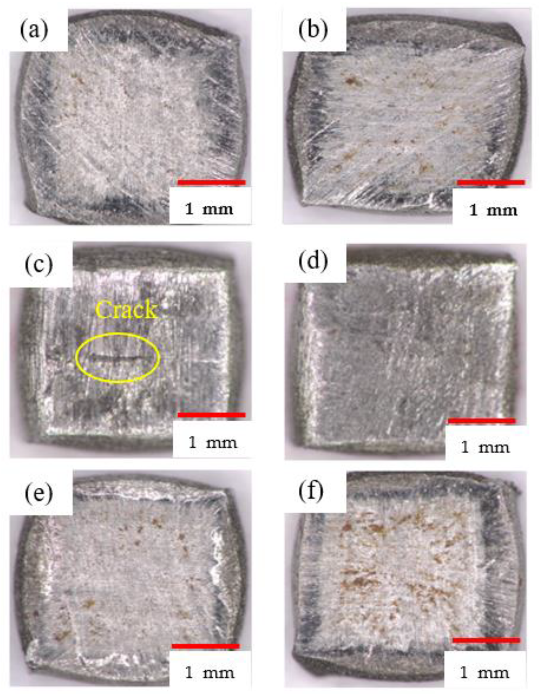
3.1. Observation of the Fracture Surfaces of the Alloy B and Gr.92 Steels under Different Heat Treatment Conditions
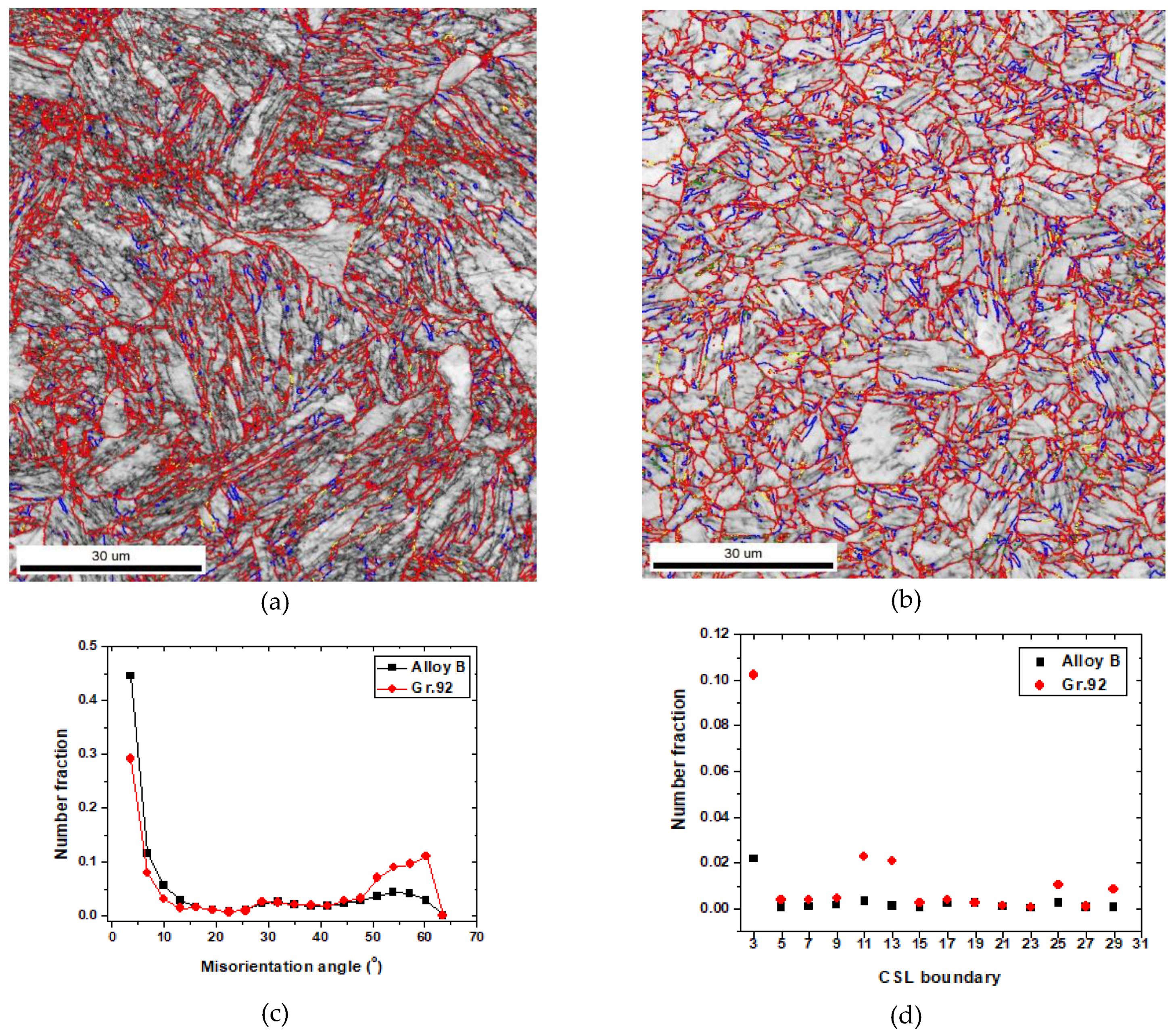
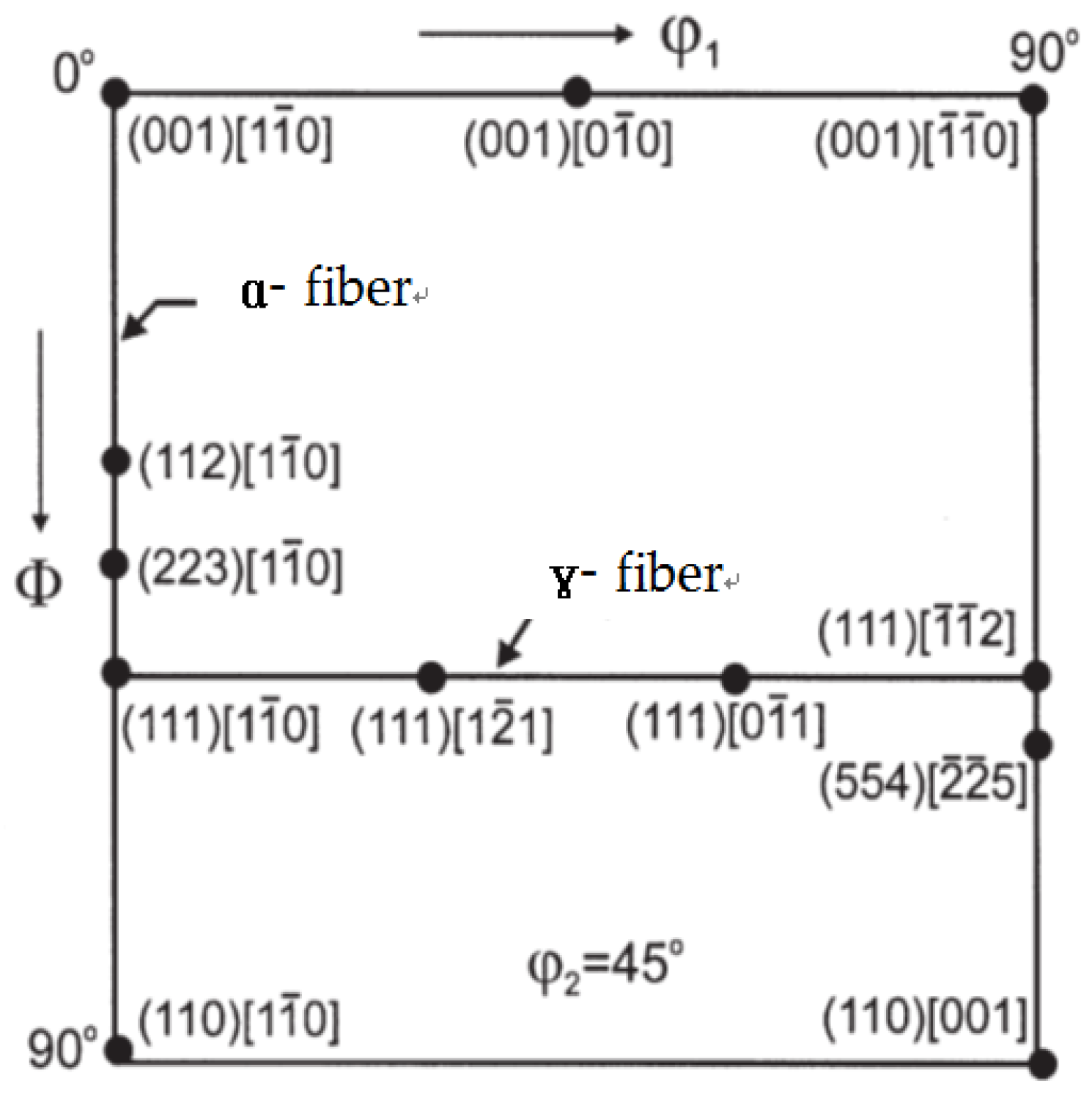
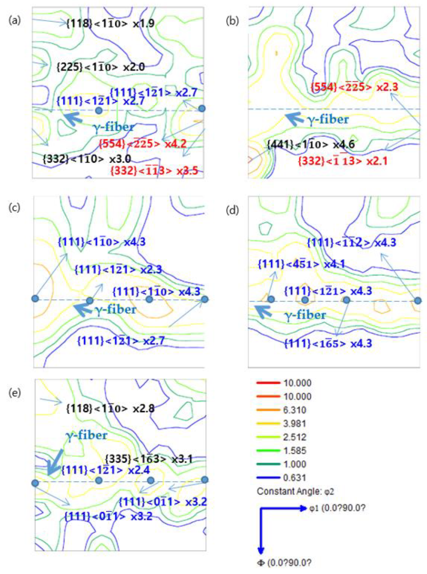
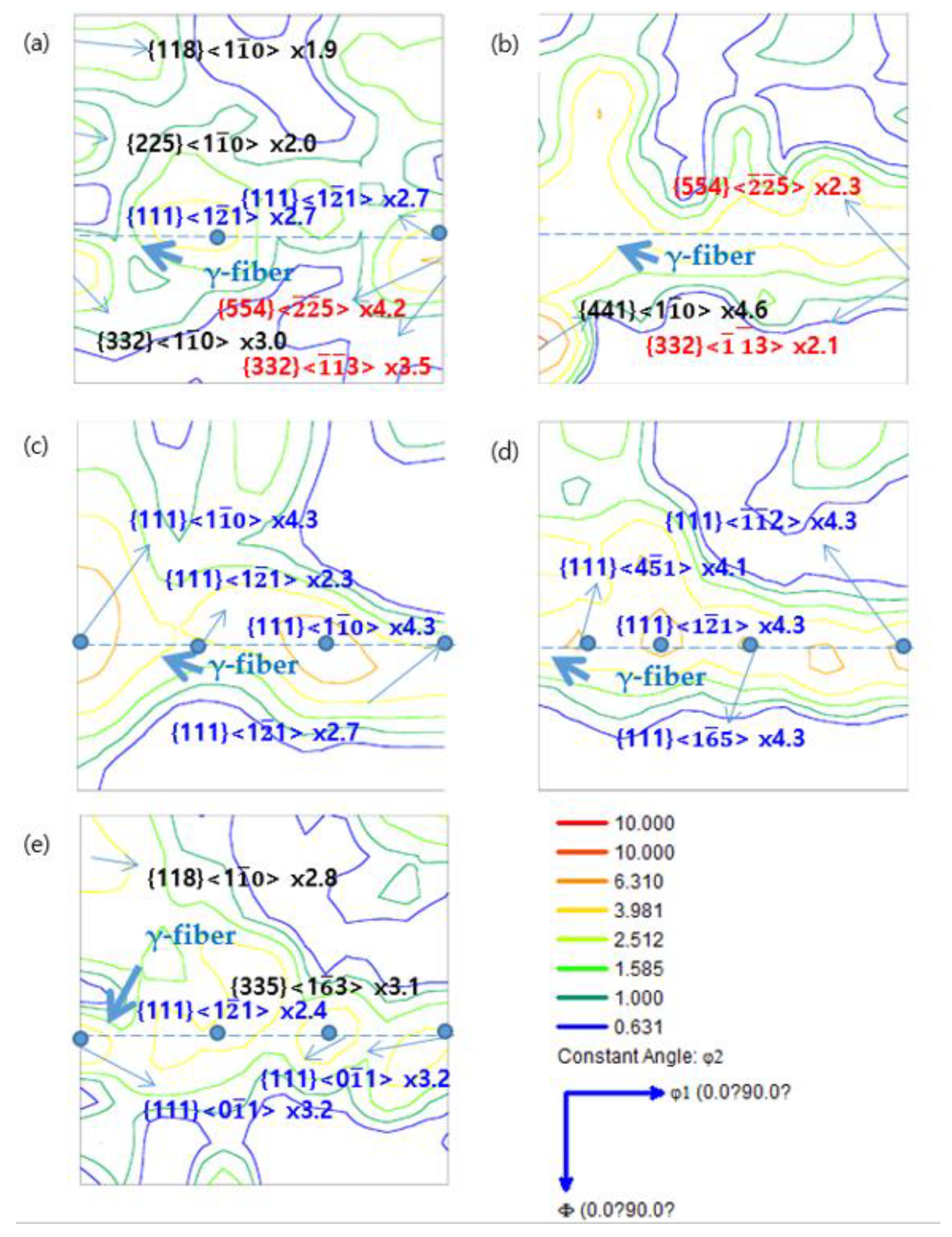
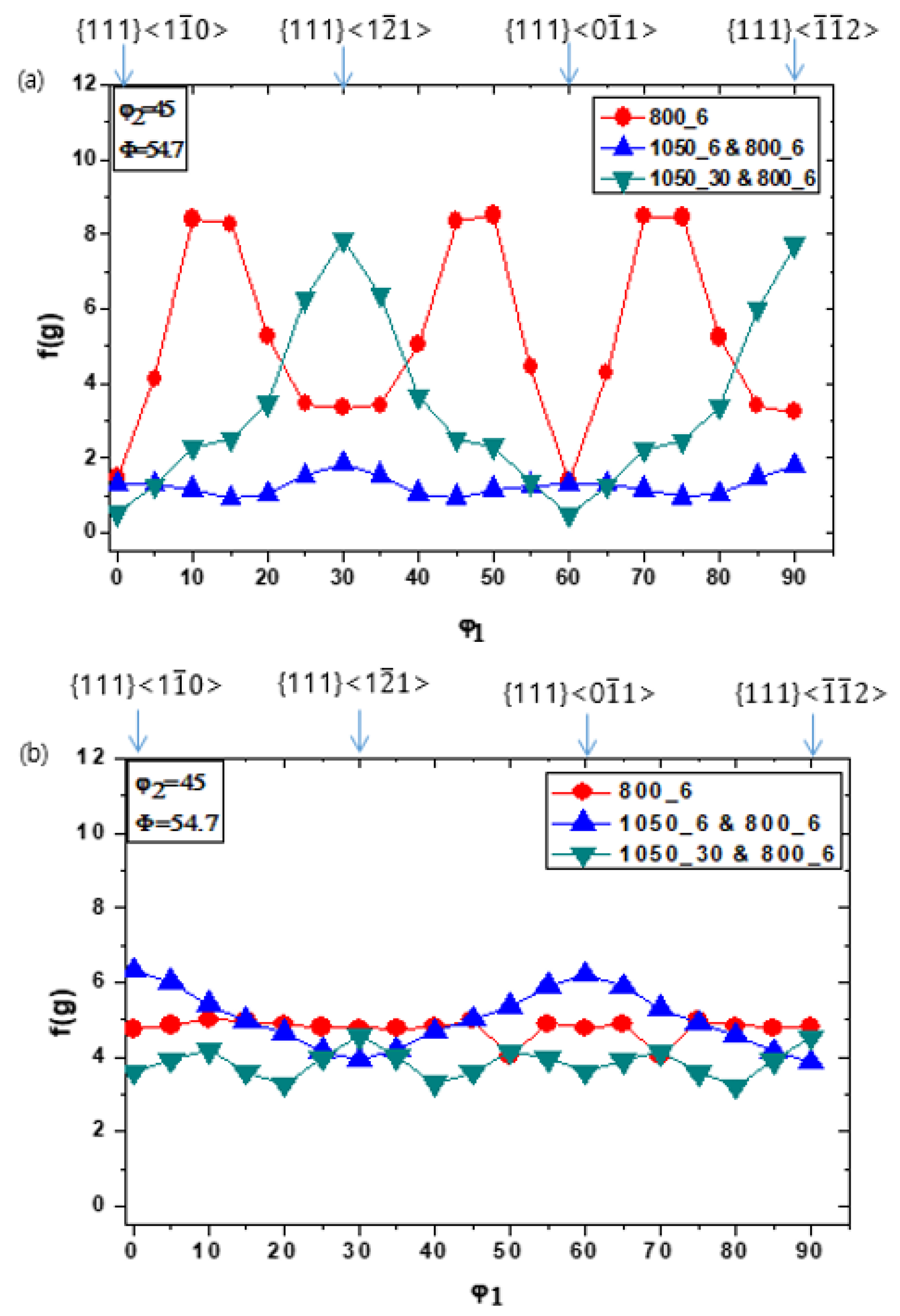
The fracture surface of the rolled alloy B plate subjected to normalization and tempering is shown in Figure 3. The alloy B plate was characterized using scanning electron microscopy (SEM) to determine its mode of fracture, as shown in Figure 3b. The fracture surface of the plate showed transgranular cleavage facets. The fractograph clearly revealed that the mode of fracture was brittle.
The OM images of the alloy B and Gr.92 steel specimens heat-treated under different conditions are shown in Figure 4 and Figure 5, respectively. The rolling process resulted in the formation of an elongated grain boundary in the RD of the specimens. Elongated grain boundary was observed when the alloy B and Gr.92 specimens were only tempered (800 °C, 6 min) without normalization. However, the alloy B specimens heat-treated at 1050 °C for 6 min and 800 °C for 6 min showed elongated grain boundaries and the deformation of the structure. The remaining heat treatment conditions yielded a tempered lath martensite structure.
The image quality map and grain boundary character distribution (GBCD) of the alloy B and Gr.92 specimens heat-treated under the 1050 °C, 6 min and 800 °C, 6 min are shown in Figure 6. An image quality map was derived from EBSD analysis of the ND, where the high angle grain boundary (HAGB, misorientation angle > 15, and color code: red) and coincidence site lattice (CSL, color key: Σ3—blue, Σ11—yellow, Σ17—violet, Σ19—brown, Σ25—orange) are shown in Figure 6a,b. The image quality map of the alloy B appeared as an elongated HAGB. In the contrast, the Gr.92 exhibited an equiaxed HAGB. The fraction of low angle grain boundary (LAGB) and HAGB in alloy B were 0.65 and 0.30, respectively. In the case of Gr.92, LAGB and HAGB values were 0.41 and 0.39, respectively. The mis-orientation angle distribution plot shows that the fraction of LAGB in alloy B was higher than that of Gr.92. The reason for this is that the fraction of LAGB was high due to the formation of cell and sub grain during the cold deformation when alloy B does not undergo complete phase transformation from martensite to austenite despite the normalizing heat treatment. In contrast, the fraction of HAGB in the Gr.92 was higher than that of Alloy B because the complete phase transformation formed a lot of prior austenite grain boundary (PAGB) and tempered martensite.
Figure 6d shows that the number fraction of the CSL boundary (Σ3–29) in alloy B and Gr.92 accounted for about 0.04 and 0.18 of the total number of boundaries, respectively. Among the CSL boundaries, the most prominent were Σ3, Σ11, Σ13, and Σ25. The CSL boundaries of Σ3 and Σ11 could be preferentially found within regions of martensite.

3.2. Texture

The typical main texture components of cold-rolled low-carbon steels in the φ2 = 45° section of the ODF are shown in Figure 7 [19]. Body-centered cubic metals and alloys tend to form α- and γ-fibers. Typically, α-fibers exhibit the orientation and a common <110> crystal axis parallel to the RD, i.e., the {hkl}<110> orientations such as {001}<110>, {112}<110>, and {111}<110> at (φ1, Φ, φ2) = (0°, 0°, 45°), (0°, 35°, 45°), and (0°, 54.7°, 45°), respectively, in the Euler space. On the other hand, γ-fibers exhibit orientations with the {111} crystal axis parallel to the ND i.e., the {111}<uvw> orientations such as {111}<110> and {111}<112> at (φ1, Φ, φ2) = (60°, 54.7°, 45°) and (90°, 54.7°, 45°), respectively, in the Euler space. In addition, the Goss orientation {011}<100> is typically observed at (90°, 90°, 45°) in the Euler space [19,20].
The ODFs for the φ2 = 45° sections of the alloy B and Gr.92 specimens heat-treated under different conditions are shown in Figure 8 and Figure 9, respectively. The evolution of the ODF intensity of the γ-fibers in the alloy B and Gr.92 specimens under different heat treatment conditions is shown in Figure 10. Under all the heat treatment conditions, both the alloy B and Gr.92 specimens showed the development of α-fibers, which exhibited orientation and a common <110> crystal axis parallel to the RD. In the case of the alloy B steel, the as-received specimen and the specimens heat-treated at 1050 °C for 6 min and 800 °C for 6 min did not develop γ-fiber components, which is advantageous for formability. In all the other heat treatment conditions, γ-fiber components were developed. On the other hand, the Gr.92 steel showed γ-fiber components under all the conditions. This is because the γ-fiber components were developed uniformly under the initial conditions in the case of the Gr.92 steel.

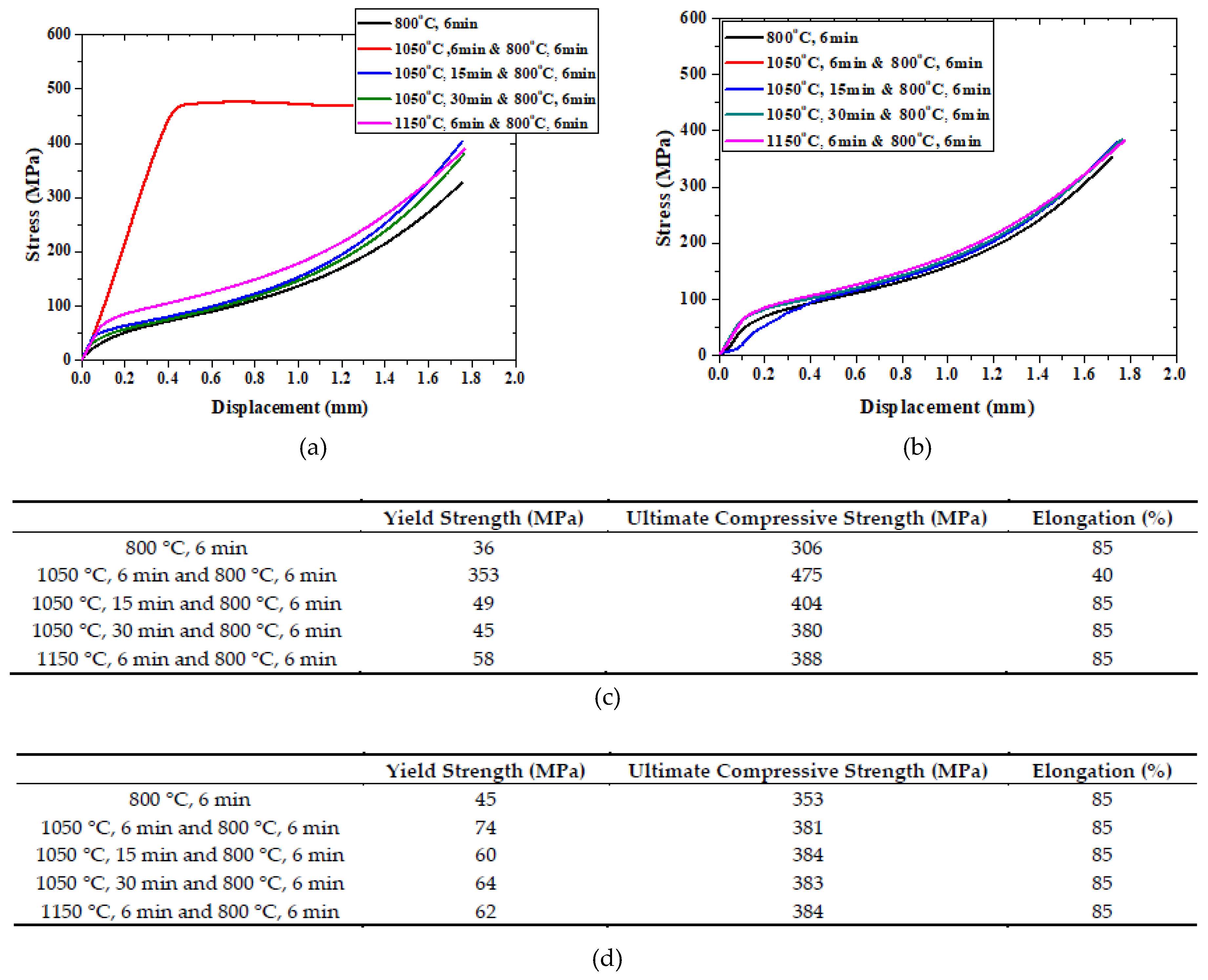
3.3. Effects of Heat Treatment Conditions on the Mechanical Properties of the Steels

The results of the compression tests of the alloy B and Gr.92 steels along the ND at 298 K are shown in Figure 11. Except for the 1050 °C, 6 min and 800 °C, 6 min conditions, all the conditions showed the same compression test results. The ultimate reduction in height Rc (%) is calculated as:
R c ( % )   =   H h H     ×   100
where H is the height of the specimen before test and h is the height of the specimen after test. The compressive test was performed up to 1.7 mm due to the limitation of the test equipment. Additionally, the 0.2% yield strength and the ultimate compressive strength are obtained by recording the displacement and load. In the case of the alloy B specimens (along the ND), the hardening and strength increased rapidly in the elastic region. Therefore, fracture occurred during the elastic-to-plastic transition. The images of the alloy B and Gr.92 specimens after the compression along the ND are shown in Figure 12. In the case of the Gr.92 specimens, when the rolling was successful without fracture, cracks were absent in all the directions. In the case of the alloy B, specimens heat-treated under the 1050 °C, 6 min and 800 °C, 6 min conditions (wherein fracture was observed), cracks were observed in the ND.

4. Discussion

In this study, the effect of heat treatment on the fracture behavior of alloy B steel with boron (B) contents as high as 130 ppm was investigated. As shown in Figure 3 and Figure 4, the alloy B steel showed cleavage fracture only under the 1050 °C, 6 min and 800 °C, 6 min conditions. Tempered lath martensite and deformed microstructures were obtained after the heat treatment. In the case of tempering, the austenite phase transformation does not occur, so some deformed microstructure remains [21]. On the other hand, the deformed microstructure transforms into an austenitic structure by heating at the phase transformation temperature (Ac3, the temperature at which the α-to-γ transformation commences) or higher temperatures under the normalized condition [22]. The deformed microstructure disappears during the austenitization and a lath martensite structure is formed with a high dislocation density in the PAGB upon cooling [23]. PAGBs are divided into packet boundaries parallel to a group of laths with the same habit plane, and each packet boundary is further divided into block boundaries with the same orientation as that of the lath group. The lath and packet are parallel to the {111} plane of the austenite phase and exhibit a K-S orientation relationship [24]. In a packet, there are six variants with different direction parallel relationships on the same conjugate parallel close-packed plane (e.g., (111)γ // (011)α) [24,25].
However, the alloy B steel specimens heat-treated under the 1050 °C, 6 min and 800 °C, 6 min conditions showed deformed microstructure. This can be attributed to the segregation of B at the grain boundaries. It is well known that grain boundary segregation of trace element (such as B, As, Sn, Cu etc.) affect the chemical composition of interfaces, causing increased material embrittlement due to a reduction of cohesion at the interfaces, or it can stabilize the nanocrystalline structure through reduced mobility of the grain boundaries [26,27,28,29,30].
In Figure 13 and Figure 14, the alloy B specimens that were heat-treated to 1050 °C for 6 min and 800 °C for 6 min were used to conduct a Nano-SIMS analysis of the precipitate and the distribution of boron at grain boundaries.
The segregation behavior of Alloy B specimens heat-treated to 1050 °C for 6 min and 800 °C for 6 min is explained by precipitation. Cr-based carbide (Cr, Fe)23(B, C)6 was the main precipitate of 9–12% Cr FM steel. When the content of boron is 0.004 wt % or more, a brittle Fe2B precipitate is formed [31,32]. Fe2B precipitate was not observed frequently. Equilibrium phase diagrams predicted by thermodynamic calculations demonstrate that the Fe2B phase constitutes a fraction of 0.001 at temperatures exceeding 800 °C [32]. These are also similar to the Nano-SIMS results. The result of Nano-SIMS analysis demonstrated that the B and C distributions produced a behavior almost identical to the Cr and Fe distribution. If the observed Cr and Fe elements are assumed to have the distribution of (Cr, Fe)23(B, C)6, this indicates that the amount of boron incorporated into the (Cr, Fe)23(B, C)6 precipitate was highly dependent on the location of the precipitate associated with the PAGB [3,4]. Also, trace element Nb, Ta, and V affect to form of (Cr, Fe)23(B, C)6. The combination of boron and these elements suppress the α-to-γ transformation by stabilizing austenite due to formation of MX carbides with high thermal stability and reducing the rate of carbon diffusion and the inhibition of (Cr, Fe)23(B, C)6 [31]. The Ac3 of the alloy B steel was measured by thermomechanical analysis and was compared with that of the Gr.92 steel [32]. The alloy B specimens showed higher phase transformation temperatures than the Gr.92 specimens, as can be observed from Table 2. We believe that the precipitate is not the cause of the failure that occurred during processing. This is because there was no precipitate around the fracture surface.
The different textures of the two steels can be attributed to their different B contents. The texture of both the steels depended on the fraction of the austenite phase present in them during the intercritical annealing. During the α→ γ → α transformation, a texture with a strong {111} component develops by intercritical annealing with the transformation of a certain amount of the γ phase [33,34,35]. Therefore, in the case of the alloy B steel specimens, γ-fibers, which become parallel to the ND during the α→ γ → α transformation because of the incomplete normalization, were not formed.
Figure 11 shows the compression test results of the alloy B steel along the ND. Fracture commenced at the point where hardening occurred rapidly in the elastic region and the strength increased suddenly, resulting in the transformation of the elastic region into the fracture region. This is because the γ-fiber component did not develop on the ND plane and the plastic deformation did not occur in the ND plane.
Crack initiation occurs along the slip bands in a grain or at the grain boundary on the surface. In the crystallographic mode of ferrite steels, cleavage involves the separation of atomic bonds along the low index {001} crystal plane [36]. The separation process along the low index plane prefers to lower the surface energy. The low index plane lies on the {001} plane and other low-index planes such as {110}, {112}, and {123}. It has been reported that cleavage fracture is caused by the lack of slip bands [37]. This phenomenon was observed in the 1050 °C, 6 min and 800 °C, 6 min alloy B specimens because the ND // {111} plane (γ-fiber), which ensured that formability does not develop. Thus, the slip system did not function properly during the rolling and plastic deformation does not occur on the ND plane and fracture occurs on it.

5. Conclusions

In this study, a modified 9Cr-2W steel (Alloy B) was developed for application as the fuel cladding with good creep performance for SFRs. It is expected that the investigation of the properties and manufacturing processes of these alloys will significantly contribute to expanding the applicability of components with high-temperature strength and creep characteristics for nuclear reactors in the future.
The analysis of the fracture of the alloy B steel sample during the manufacturing process showed that an increase in the B content resulted in an increase in the α → γ phase transformation temperature such that sufficient transformation did not occur under the normalizing condition. The effect of heat treatment on the alloy samples depended on their B contents. Under the incomplete heat treatment conditions, the γ-fiber components, which are advantageous for formability, did not develop in the samples. It was assumed that cracks occurred when the elastic-to-plastic deformation transition occurred in the ND during the rolling process, thereby resulting in failure. Therefore, it is necessary to avoid intermediate heat treatment conditions in which γ-fibers do not fully develop, i.e., an imperfect normalization should be avoided.

Author Contributions

Writing—original draft preparation, review and editing, H.M.H.; conceptualization; J.H.K.; project administration; S.H.K.; supervision; J.R.K. and W.J.M.

Funding

This research was funded by the Ministry of Science and ICT of South Korea (No. 2012M2A8A2025646).

Acknowledgments

This work was supported by the National Nuclear R & D program through the Sodium-cooled Fast Reactor Development Agency funded by the Ministry of Science and ICT of South Korea (2012M2A8A2025646). We would like to thank Editage (www.editage.co.kr) for editing and reviewing this manuscript for English language.

Conflicts of Interest

The authors declare no conflict of interest.

References

  1. Kim, J.H.; Baek, J.H.; Kim, S.H.; Lee, C.B.; Na, K.S.; Kim, S.J. Effect of hot rolling process on the mechanical and microstructural property of the 9Cr-1Mo steel. Ann. Nucl. Energy 2011, 38, 2397–2403. [Google Scholar] [CrossRef]
  2. Heo, H.M. Effect of Boron on the Formability of Modified 9Cr-2W steel. Ph.D. Thesis, Hanyang University, Ansan, Korea, February, 2019. [Google Scholar]
  3. Jeong, E.H.; Park, S.G.; Kim, S.H.; Kim, Y. Do Evaluation of the effect of B and N on the microstructure of 9Cr–2W steel during an aging treatment for SFR fuel cladding tubes. J. Nucl. Mater. 2015, 467, 527–533. [Google Scholar] [CrossRef]
  4. Heo, H.M.; Jeong, E.H.; Kim, S.H.; Kim, J.R. Comparison between effect of B and N on the microstructure of modi fi ed 9Cr-2W steel during aging and creep. Mater. Sci. Eng. A 2016, 670, 106–111. [Google Scholar] [CrossRef]
  5. Kim, J.H.; Heo, H.M.; Kim, S.H. Effect of an intermediate process on the microstructure and mechanical properties of HT9 fuel gadding. J. Korean Inst. Met. Mater. 2013, 51, 893–900. [Google Scholar] [CrossRef]
  6. György, H.; Czifrus, S. Investigation on the potential use of thorium as fuel for the Sodium-cooled Fast Reactor. Ann. Nucl. Energy 2017, 103, 238–250. [Google Scholar] [CrossRef]
  7. Kim, J.T.; Jae, M.S. A study on reliability assessment of a decay heat removal system for a sodium-cooled fast reactor. Ann. Nucl. Energy 2018, 120, 534–539. [Google Scholar] [CrossRef]
  8. Kim, T.K.; Kim, S.H.; Lee, C.B. Effects of an intermediate heat treatment during a cold rolling on the tensile strength of a 9Cr-2W steel. Ann. Nucl. Energy 2009, 36, 1103–1107. [Google Scholar] [CrossRef]
  9. Garner, F.A.; Toloczko, M.B.; Sencer, B.H. Comparison of swelling and irradiation creep behavior of fcc-austenitic and bcc-ferritic/martensitic alloys at high neutron exposure. J. Nucl. Mater. 2000, 276, 123–142. [Google Scholar] [CrossRef]
  10. Lee, C.B.; Cheon, J.S.; Kim, S.H.; Park, J.Y.; Joo, H.K. Metal Fuel Development and Verification for Prototype Generation IV Sodium-Cooled Fast Reactor. Nucl. Eng. Technol. 2016, 48, 1096–1108. [Google Scholar] [CrossRef] [Green Version]
  11. Kim, S.H.; Song, B.J.; Ryu, W.S.; Hong, J.H. Creep rupture properties of nitrogen added 10Cr ferritic/martensitic steels. J. Nucl. Mater. 2004, 329–333, 299–303. [Google Scholar] [CrossRef]
  12. Jeong, E.H.; Kim, J.H.; Kim, S.H.; Kim, Y. Do Influence of B and N on the microstructural characteristics and high-temperature strength of 9Cr-2W steel during an aging treatment. Mater. Sci. Eng. A 2017, 700, 701–706. [Google Scholar] [CrossRef]
  13. Bunge, H.J. Texture Analysis in Materials Science; Butterworths: London, UK, 1982; ISBN 9780408106429. [Google Scholar]
  14. Choi, S.H.; Jin, Y.S. Evaluation of stored energy in cold-rolled steels from EBSD data. Mater. Sci. Eng. A 2004, 371, 149–159. [Google Scholar] [CrossRef]
  15. Seol, J.B.; Lee, B.H.; Choi, P.; Lee, S.G.; Park, C.G. Combined nano-SIMS/AFM/EBSD analysis and atom probe tomography, of carbon distribution in austenite/ε-martensite high-Mn steels. Ultramicroscopy 2013, 132, 248–257. [Google Scholar] [CrossRef]
  16. Abe, H.; Furugen, M. Evaluation Method of Workability in Cold Pilgering of Zirconium-based Alloy Tube. Mater. Trans. 2010, 51, 1200–1205. [Google Scholar] [CrossRef]
  17. Abe, H.; Furugen, M. Method of evaluating workability in cold pilgering. J. Mater. Process. Technol. 2012, 212, 1687–1693. [Google Scholar] [CrossRef]
  18. Heo, H.-M.; Kim, J.-H.; Kim, S.-H.; Kim, J.-R. Evaluation of workability on the microstructure and mechanical property of modified 9Cr-2W steel for fuel cladding by cold drawing process and intermediate heat treatment condition. Metals (Basel) 2018, 8, 193. [Google Scholar] [CrossRef]
  19. Humphreys, F.J.; Hatherly, M. Recrystallization and Related Annealing Phenomena; Sleeman, D., Ed.; Elsevier: Kidlington, UK, 2012; ISBN 9788578110796. [Google Scholar]
  20. Huh, M.Y.; Engler, O. Effect of intermediate annealing on texture, formability and ridging of 17%Cr ferritic stainless steel sheet. Mater. Sci. Eng. A 2001, 308, 74–87. [Google Scholar] [CrossRef]
  21. Birosca, S.; Ding, R.; Ooi, S.; Buckingham, R.; Coleman, C.; Dicks, K. Nanostructure characterisation of flow-formed Cr–Mo–V steel using transmission Kikuchi diffraction technique. Ultramicroscopy 2015, 153, 1–8. [Google Scholar] [CrossRef]
  22. Klueh, R.L.; Harries, D.R. High-Chromium Ferritic and Martensitic Steels for Nuclear Applications; ASTM International: West Conshohocken, PA, USA, 2001; ISBN 978-0-8031-2090-7. [Google Scholar]
  23. Saroja, S.; Vijayalakshmi, M.; Raghunathan, V.S. Influence of cooling rates on the transformation behaviour of 9Cr-1 Mo-O.07C steel. J. Mater. Sci. 1992, 27, 2389–2396. [Google Scholar] [CrossRef]
  24. Morito, S.; Huang, X.; Furuhara, T.; Maki, T.; Hansen, N. The morphology and crystallography of lath martensite in Fe-C alloy steels. Acta Mater. 2006, 54, 5323–5331. [Google Scholar] [CrossRef]
  25. Maki, T. Morphology and substructure of martensite in steels. Phase Transform. Steels 2012, 2, 34–58. [Google Scholar]
  26. Lejček, P.; Hofmann, S.; Paidar, V. The significance of entropy in grain boundary segregation. Materials (Basel) 2019, 12, 492. [Google Scholar] [CrossRef]
  27. Watanabe, T. An approach to grain-boundary design for strong and ductile polycrystals. Res Mech. 1984, 11, 47–84. [Google Scholar]
  28. Kirchheim, R. Grain coarsening inhibited by solute segregation. Acta Mater. 2002, 50, 413–419. [Google Scholar] [CrossRef]
  29. Briant, C.L. Impurities in Engineering Materials: Impact, Reliability and Control; Dekker, M., Ed.; Routledge: New York and Basel, 1999. [Google Scholar]
  30. El-Shennawy, M.; Farahat, A.I.; Masoud, M.I.; Abdel-Aziz, A.I. Effect of Boron Content on Metallurgical and Mechanical. Int. J. Mech. Eng. 2016, 5, 1–14. [Google Scholar]
  31. Hara, T.; Asahi, H.; Uemori, R.; Tamehiro, H. Role of Combined Addition of Niobium and Boron and of Molybdenum and Boron on Hardnenability in Low Carbon Steels. ISIJ Int. 2008, 44, 1431–1440. [Google Scholar] [CrossRef]
  32. Wang, S.S.; Peng, D.L.; Chang, L.; Hui, X.D. Enhanced mechanical properties induced by refined heat treatment for 9Cr-0.5Mo-1.8W martensitic heat resistant steel. Mater. Des. 2013, 50, 174–180. [Google Scholar] [CrossRef]
  33. Vivas, J.; Capdevila, C.; Jimenez, J.; Benito-Alfonso, M.; San-Martin, D. Effect of Ausforming Temperature on the Microstructure of G91 Steel. Metals (Basel) 2017, 7, 236. [Google Scholar] [CrossRef]
  34. HASHIMOTO, O.; SATOH, S.; TANAKA, T. Development of {111} Texture in Intercritical Annealing of Low Carbon Steels. Trans. Iron Steel Inst. Jpn. 1987, 27, 746–754. [Google Scholar] [CrossRef]
  35. Obasi, G.C.; Birosca, S.; Quinta Da Fonseca, J.; Preuss, M. Effect of β grain growth on variant selection and texture memory effect during α → β → α phase transformation in Ti-6Al-4V. Acta Mater. 2012, 60, 1048–1058. [Google Scholar] [CrossRef]
  36. Tu, M.Y.; Hsu, C.A.; Wang, W.H.; Hsu, Y.F. Comparison of microstructure and mechanical behavior of lower bainite and tempered martensite in JIS SK5 steel. Mater. Chem. Phys. 2008, 107, 418–425. [Google Scholar] [CrossRef]
  37. Gross, D.; Seelig, T. Fracture Mechanics With an lntroduction to Micromechanics; Ling, F.F., Ed.; Spring: Heidelberg, Germany, 2011; ISBN 9781118147757. [Google Scholar]
Figure 1. Schematic of the experimental procedure. AC: air cooling.
Metals 09 00904 g001
Figure 2. Sampling and compression of the specimens. RD: rolling direction; TD: transverse direction; ND: normal direction.
Metals 09 00904 g002
Figure 3. Alloy B steel during the rolling process under the tempering condition after the normalization: (a) fractograph of failed part and (b) scanning electron microscopy (SEM) image.
Metals 09 00904 g003
Figure 4. Optical microscope (OM) images of the alloy B steel specimens subjected to different intermediate heat treatment conditions: (a) as-received; (b) 800 °C, 6 min; (c) 1050 °C, 6 min and 800 °C, 6 min; (d) 1050 °C, 30 min, and 800 °C, 6 min; (e) 1150 °C, 6 min, and 800 °C, 6 min.
Metals 09 00904 g004
Figure 5. OM images of the Gr.92 steel specimens subjected to different intermediate heat treatment conditions: (a) as-received; (b) 800 °C, 6 min; (c) 1050 °C, 6 min, and 800 °C, 6 min; (d) 1050 °C, 30 min, and 800 °C, 6 min; (e) 1150 °C, 6 min, and 800 °C, 6 min.
Metals 09 00904 g005
Figure 6. The image quality map and grain boundary character distribution (GBCD) of the alloy B and Gr.92 specimens heat-treated under the 1050 °C, 6 min and 800 °C, 6 min conditions: (a,b) the image quality map of alloy B and Gr.92 are denoted by the high angle grain boundary (HAGB) (mis orientation angle > 15, color code: red) and CSL boundary (color key: Σ3—blue, Σ11—yellow, Σ17—violet, Σ19—brown, Σ25—orange (c) misorientation angle distribution plot, and (d) coincidence site lattice (CSL) boundary distribution plot.
Metals 09 00904 g006
Figure 7. Main texture components of cold-rolled low carbon steels in the φ2 = 45° section of the orientation distribution functions (ODF) [19].
Metals 09 00904 g007
Figure 8. φ2 = 45° section of the ODF in the alloy B steel specimens heat-treated under different conditions: (a) as-received, (b) 800 °C, 6 min, (c) 1050 °C, 6 min, and 800 °C, 6 min, (d) 1050 °C, 30 min, and 800 °C, 6 min, and (e) 1150 °C, 6 min, and 800 °C, 6 min.
Metals 09 00904 g008
Figure 9. φ2 = 45° section of the ODF of the Gr.92 steel specimens heat-treated under different conditions: (a) as-received, (b) 800 °C, 6 min, (c) 1050 °C, 6 min, and 800 °C, 6 min, (d) 1050 °C, 30 min, and 800 °C, 6 min, and (e) 1150 °C, 6 min, and 800 °C, 6 min.
Metals 09 00904 g009
Figure 10. Evolution of the ODF intensity f(g) in the γ-fiber (Φ = 54.7° and φ2 = 45°, constant) components of the steels subjected to different intermediate heat treatment conditions: (a) alloy B and (b) Gr.92.
Metals 09 00904 g010
Figure 11. Compression test of the specimens heat-treated under different conditions along the ND: (a) alloy B, (b) Gr.92, (c) mechanical properties of Alloy B, and (d) mechanical properties of Gr.92.
Metals 09 00904 g011
Figure 12. Images of the specimens heat-treated under different conditions after the compression test along the ND: (a) alloy B 800 °C, 6 min, (b) Gr.92 800 °C, 6 min, (c) alloy B 1050 °C, 6 min, and 800 °C, 6 min (d) Gr.92 1050 °C, 6 min, and 800 °C, 6 min, (e) alloy B 1150 °C, 6 min, and 800 °C, 6 min, and (f) Gr.92 1150 °C, 6 min, and 800 °C, 6 min.
Metals 09 00904 g012
Figure 13. Nano-secondary ion mass spectrometry (Nano-SIMS) Images of B, C, Cr, and Fe of the alloy B specimens heat-treated under the 1050 °C, 6 min and 800 °C, 6 min conditions.
Metals 09 00904 g013
Figure 14. Nano-SIMS distribution map of sputtered carbon, boron, chromium, and iron ions in the areas denoted by the arrows of the alloy B specimens heat-treated under the 1050 °C, 6 min and 800 °C, 6 min conditions: (a) #1 (b) #2.
Metals 09 00904 g014
Table 1. Chemical compositions of the alloy B and Gr.92 steel specimens (wt. %).
MaterialsCSiMnPSNiCrMoWVNbTaNBFe
Alloy B0.070.100.450.00560.0010.459.00.52.00.200.20.050.020.013Bal
Gr.920.10.450.440.020.0090.499.00.461.600.200.07-0.040.004Bal
Table 2. Phase transformation temperatures for alloy B and Gr.92 steels [32].
MaterialsAc1 (°C)Ac3 (°C)
Gr.92844879
Alloy B852909

