
Research on Maximum Power Control of Direct-Drive Wave Power Generation Device Based on BP Neural Network PID Method

School of Energy and Power, Jiangsu University of Science and Technology, Zhenjiang 212100, China
*
Author to whom correspondence should be addressed.
Actuators 2024, 13(5), 159; https://doi.org/10.3390/act13050159
Submission received: 17 March 2024
/
Revised: 10 April 2024
/
Accepted: 15 April 2024
/
Published: 24 April 2024
(This article belongs to the Special Issue Actuators in 2024)
Abstract
:Ocean wave energy is a new type of clean energy. To improve the power generation and wave energy conversion efficiency of the direct-drive wave power generation system, by addressing the issue of large output errors and poor system stability commonly associated with the currently used PID (proportional, integral, and derivative) control methods, this paper proposes a maximum power control method based on BP (back propagation) neural network PID control. Combined with Kalman filtering, this method not only achieves maximum power tracking but also reduces output ripple and tracking error, thereby enhancing the system’s control quality. This study uses a permanent magnet linear generator as the power generation device, establishes a system dynamics model, and predicts the main frequency of irregular waves through the Fast Fourier Transform method. It designs a desired current tracking curve that meets the maximum power strategy. On this basis, a comparative analysis of the control accuracy and stability of three control methods is conducted. The simulation results show that the BP neural network PID control method improves power generation and exhibits better accuracy and stability.
1. Introduction
Currently, oceans occupy 71% of the Earth’s surface area and contain vast reserves of renewable energy [1]. Among these, wave energy in the ocean is a clean and pollution-free renewable energy source. Compared to solar and wind energy, it has the advantages of high energy density, wide distribution, and a large storage capacity, making it one of the most readily exploitable and inexhaustible sources of renewable energy [2]. Therefore, researching wave energy generation systems is of significant importance. For a long time, China has been committed to the research of swing, oscillating water column, floating body type, and small-scale wave power generation devices [3]. Generally, the conversion of wave energy into electrical energy involves three stages of conversion. The first step of capturing the kinetic and potential energy of waves and the last step of converting it into electrical energy are roughly the same in existing power generation devices, differing in the second-stage conversion device. Different devices lead to different forms of secondary energy [4]. The direct-drive wave energy generation system can directly convert captured wave energy into electrical energy, significantly reducing the complexity of design and manufacturing costs [5]. Foreign scholar Henk Polinder [6] has studied and shown that among different types of linear motors, permanent magnet linear motors have higher efficiency and are more suitable for wave power generation systems.
When the generation system achieves resonance, the wave conversion device can obtain the maximum wave energy. In [7], by adjusting the electromagnetic force of the generator, the wave power generation system can achieve the resonance effect, so that the coordinated dynamic relationship between the float and the wave can be formed. In [8], the dynamic equation of the wave device is equivalent to an RLC circuit, and the inverse electromagnetic force parameters of the generator are controlled by the circuit resonance principle to achieve resonance. In the control of wave power generation systems, traditional PID control strategies are widely used due to their simple structure, such as in [9] where traditional PID control methods are used to achieve maximum power control. However, due to the nonlinear characteristics of wave power generation systems, PID control may worsen system stability. The study in [10] uses equivalent sliding mode control to track the reference current in real time and adds a robust control term to suppress disturbances, which is effective and has strong robustness. However, sliding mode control itself has chattering issues, and the output signal has large ripples. The study in [11] analyzes unknown frequency excitation forces through Fast Fourier Transform (FFT), a common method for signal main frequency prediction, identifying unknown frequency excitation forces as a composition of sinusoidal waves of different amplitudes and frequencies. BP neural networks have good adaptive capabilities, suitable for many nonlinear situations, and neural network control can be combined with other control algorithms to improve control performance [12]. Kalman filtering can perform online filtering of system states, calculate optimal estimates in real time, and improve the tracking accuracy of signals. This paper combines BP neural networks with traditional PID control algorithms, adjusting PID parameters in real time during system operation to improve system performance.
This paper designs maximum power tracking control for a direct-drive wave power generation system based on BP neural network PID control. Under regular wave excitation, it analytically solves the buoy dynamics equation and the permanent magnet linear generator equation, starting from aspects like the back electromotive force of the generator to derive the q-axis reference current, thereby achieving maximum power tracking control. Under irregular wave excitation, it uses Fast Fourier Transform to analyze the irregular excitation force, obtaining the different frequencies and amplitudes that constitute the irregular excitation force, and then uses the superposition principle to achieve maximum power tracking control. This paper employs the BP neural network PID control method to track the reference current and integrates Kalman filtering to reduce errors and improve capture efficiency. It compares other control methods and combines space vector control to realize the system’s model and verify its accuracy. The simulation results show that the proposed scheme can reduce current tracking errors and improve the system’s output power.
2. Direct-Drive Wave Power Generation System’s Working Principle
The structure of the conversion device in a direct-drive wave power generation system mainly consists of a floater and a permanent magnet linear generator. The floater captures wave energy, driving the mover of the permanent magnet linear generator to perform reciprocating linear motion. This motion induces an electromotive force (EMF) as the coils cut through the magnetic flux lines, converting mechanical energy into electrical energy. The induced EMF is then rectified through a rectification circuit for use, storage, etc. [13]. A schematic diagram of the direct-drive wave power generation system is shown in Figure 1.
2.1. Dynamics Model of Power Generation Device
Under regular waves (this is a simplification of the modeling of an irregular wave environment), the floater moves reciprocally in the vertical direction, driving the generator’s mover to move along with it. Thus, the motion of the mover in the vertical direction can be simplified for analysis [14]. This paper simplifies the analysis of the floater’s motion characteristics. Based on the small-amplitude wave theory and Newton’s second law, the motion equation of the power generation device’s mover can be obtained as follows:
where M represents the total mass of the moving parts; is the vertical acceleration of the moving parts; is the wave excitation force; is the radiation force on the floater by the waves; is the buoyancy of the floater in the waves; is the electromagnetic force from the generator; G is the weight of the system.
Under regular waves, the wave excitation force can be simplified as a sine function in the vertical direction with frequency “”, expressed as follows:
where is the amplitude of the wave excitation force; is the wave frequency.
Through theoretical analysis of Equation (1), the dynamics equation of the power generation device under regular wave excitation force can be obtained as follows [15]:
where m is the added mass from the radiation force; is the damping coefficient produced by the radiation force; is the buoyancy coefficient.
2.2. Mathematical Model of the Permanent Magnet Linear Generator
The mover of the permanent magnet linear generator performs reciprocating motion under the drive of the floater, generating an induced electromotive force (EMF) as the coils cut through the magnetic flux lines [16].
The voltage equation of the permanent magnet linear generator in the dq coordinate system is as follows [17]:
where Ud and Uq are the stator dq-axis voltages; id and iq are the stator dq-axis currents; Ld and Lq are the stator dq-axis inductances; Ed and Eq are the stator dq-axis electromotive forces; is the electrical angular velocity of the motor; Ld = Lq = Ls, Ls is the stator inductance; r is the stator resistance.
The relationship of the dq-axis electromotive forces is given by the following:
where is the magnetic flux linkage of the permanent magnet.
Since the permanent magnet linear generator can be regarded as an unrolled version of a rotary motor, the velocity of the linear generator’s mover can be converted to the rotary motor’s rotational speed [18], with the relationship given by the following:
where n is the number of pole pairs of the motor; is the pole pitch of the motor; v is the velocity of the mover.
Combining Equations (4)–(6), the mathematical model of the permanent magnet linear generator can be derived as follows:
Additionally, the back electromotive force equation of the generator is expressed as follows [19]:
3. Power Tracking Control Strategy
3.1. Regular Wave Analysis
The electromagnetic force can also be expressed as follows [20]:
where is the equivalent damping coefficient.
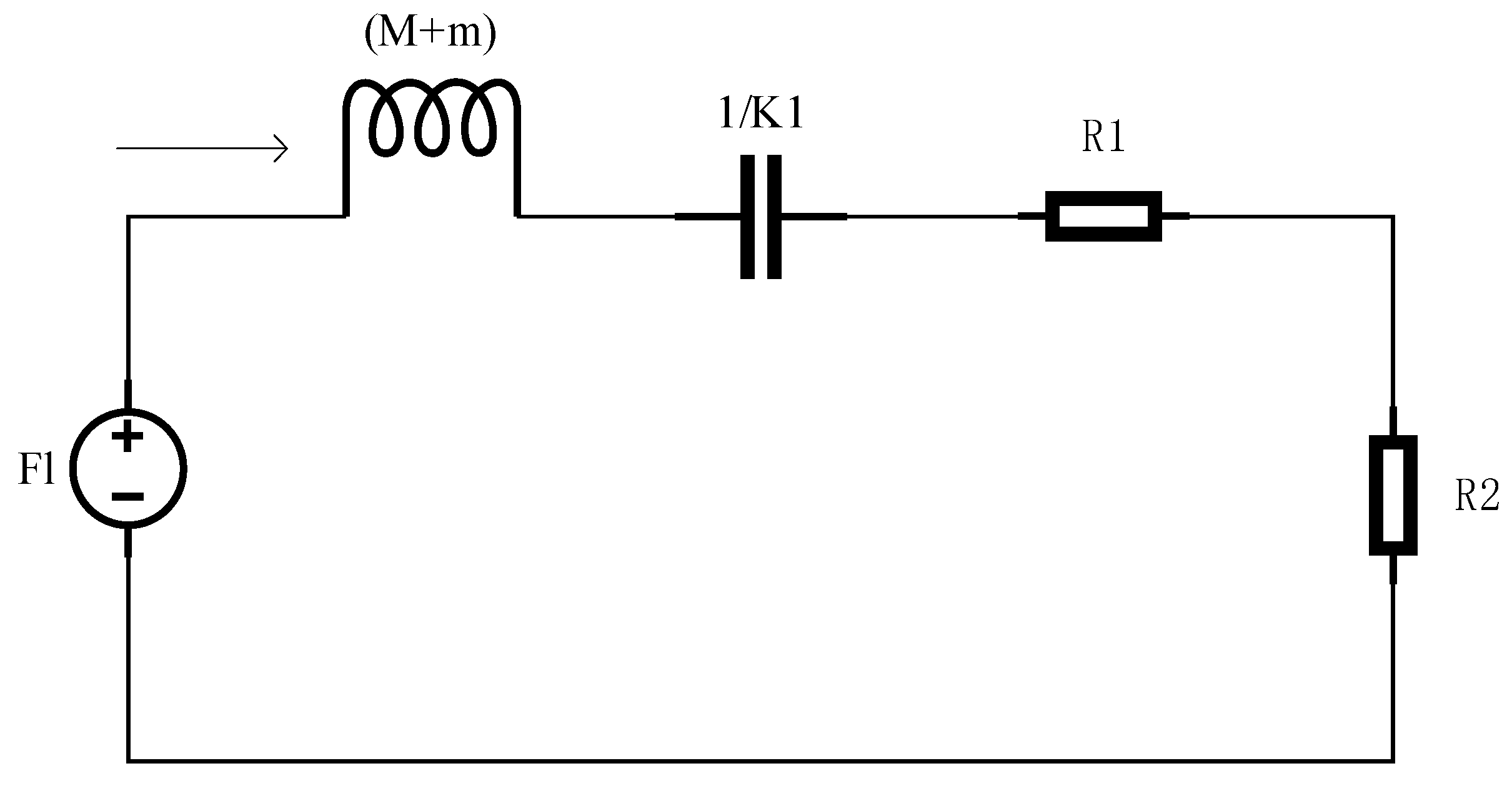
Combining Equation (9) with Equation (3), we obtain the following:
Equation (10) can be regarded as an RLC equivalent circuit, as shown in Figure 2, where can be considered the power source and can be considered the current. This allows the problem of obtaining maximum power to be transformed into finding the maximum power across resistance . According to basic circuit principles, the power across resistance is calculated as follows:
In the equation, only is variable. Deriving for maximum power, the condition for to achieve maximum value is as follows:
When is set according to the condition in Equation (12), the wave power generation system can capture the maximum energy. Combining Equations (8) and (9), the q-axis reference current value under maximum power can be obtained as follows:
Therefore, by tracking the q-axis current and controlling the back electromotive force, the maximum wave energy can be obtained [21].
3.2. Irregular Wave Analysis
Under sinusoidal regular waves, maximum power tracking control can be achieved using the control strategy mentioned above. However, in reality, waves are of an irregular waveform. An irregular waveform can be considered a superposition of an unknown, infinitely long sine and cosine signal with a disturbance signal. Therefore, irregular waveforms can undergo mathematical analysis, breaking them down into irregular signals composed of sine signals of different amplitudes and frequencies. The FFT method can analyze the amplitude and frequency of irregular waveforms. Based on the maximum power control strategy for regular waves and the principle of superposition [22], the maximum power control conditions for irregular waves can be implemented. The excitation force of irregular waves is shown in Equation (14).
Combining Equation (10) with Equation (14), we can obtain the following:
The condition for maximum power tracking is as follows:
By combining Equations (8) and (16), the q-axis tracking current required under maximum power can be obtained, as shown in Equation (17).
4. Controller Analysis and Design
4.1. BP Neural Network Controller Design
In actual ocean waves, due to changes in wave conditions and parameters, the system’s performance can be affected. By combining the BP neural network control algorithm with the PID controller for application in the system, the BP neural network can adjust the parameters of the PID controller according to the operating state of the system, stabilizing the output power of the generation system and improving the accuracy of signal tracking.
The BP neural network PID controller utilizes the powerful self-learning capability of the BP neural network to adjust the PID control parameters in real time online based on the operating state of the controlled system [23], achieving adaptive control of the controlled object.
The structure of the BP neural network primarily consists of an input layer, hidden layers, and an output layer, adopting a 3-5-3 structure, as shown in Figure 3.
The input to the neural network’s input layer is as follows:
is the input to the neural network’s input layer; is the tracking error.
The inputs and outputs of the hidden layer are as follows:
is the input of the hidden layer, represents the weights from the input layer to the hidden layer, and is the output of the hidden layer.
The output of the output layer is as follows:
represents the weights from the hidden layer to the output layer, and is the output of the output layer.
Combining the BP neural network algorithm with the PID control algorithm, its structure diagram is as shown in Figure 4.
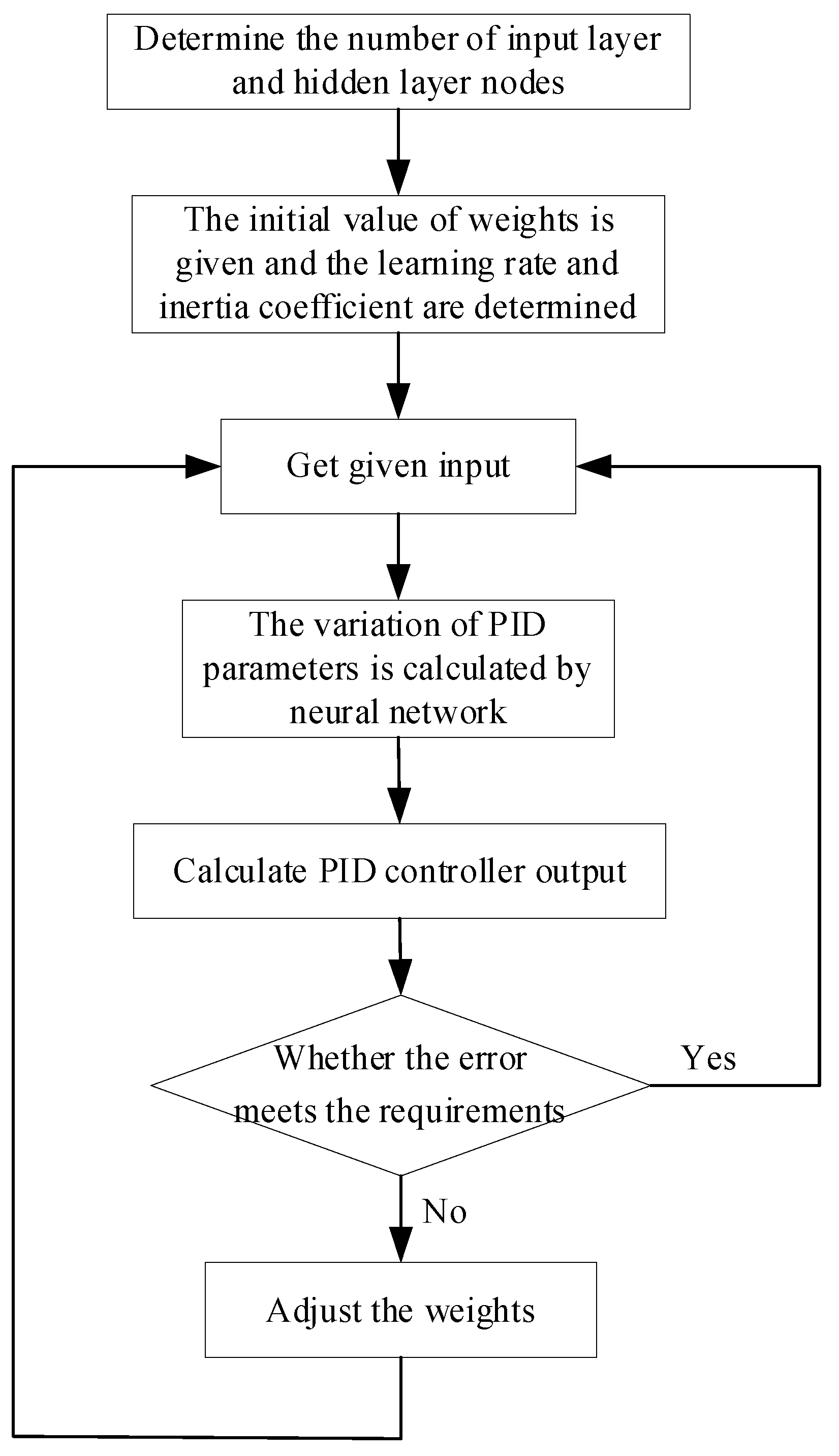
The workflow of the BP neural network PID controller is shown in Figure 5.
4.2. Kalman Filter Design
The Kalman filter is an optimal estimation algorithm that can calculate the optimal estimation in real time of system states, using the state space method to design filters in the time domain [24]. Due to the ripple generated by the operation of the thyristor switches in the system rectifier, which significantly affects the accuracy of signal tracking, the Kalman filter is introduced. It can provide optimal estimates for the system, thereby improving the control effect of the motor.
The design of the Kalman filter can be divided into two steps: prediction and update. Prediction is based on the posterior estimate of the previous moment to estimate the current state, obtaining the prior estimate for the current moment. Update uses the current measurement to update the estimated value from the prediction phase, obtaining the posterior estimate for the current moment. According to Equation (7), the Kalman filter formula is as shown in Equation (21):
where ; ; ; T is the sampling period; ; Q is the system noise; ; R is the variance of the state variable; .
5. Simulation Analysis
5.1. Simulation Analysis Comparison
To verify the accuracy of the control strategy, a simulation model of the direct-drive wave power generation system was constructed (the simulation model was built with matlabR2022b/simulink software), and the results were validated. The simulation parameters are shown in Table 1. The structure of the generator system simulation model is illustrated in Figure 6. Based on the structural diagram, the model was built using software.
The system model was compared using three different control methods: PID control, sliding mode control, and BP neural network PID control. The simulation time was set to 20 s. The simulation compared the ripple size of the waveform and the tracking error to evaluate the control effect and analyzed the fluctuation in instantaneous power to judge the system’s stability.
Figure 7 shows the wave excitation force and the waveform at 300 times speed under BP neural network PID control. It can be observed from the figure that the two waveforms maintain the same frequency and are in phase, meeting the resonance condition of the wave power generation system, allowing the power generation device to achieve maximum power.
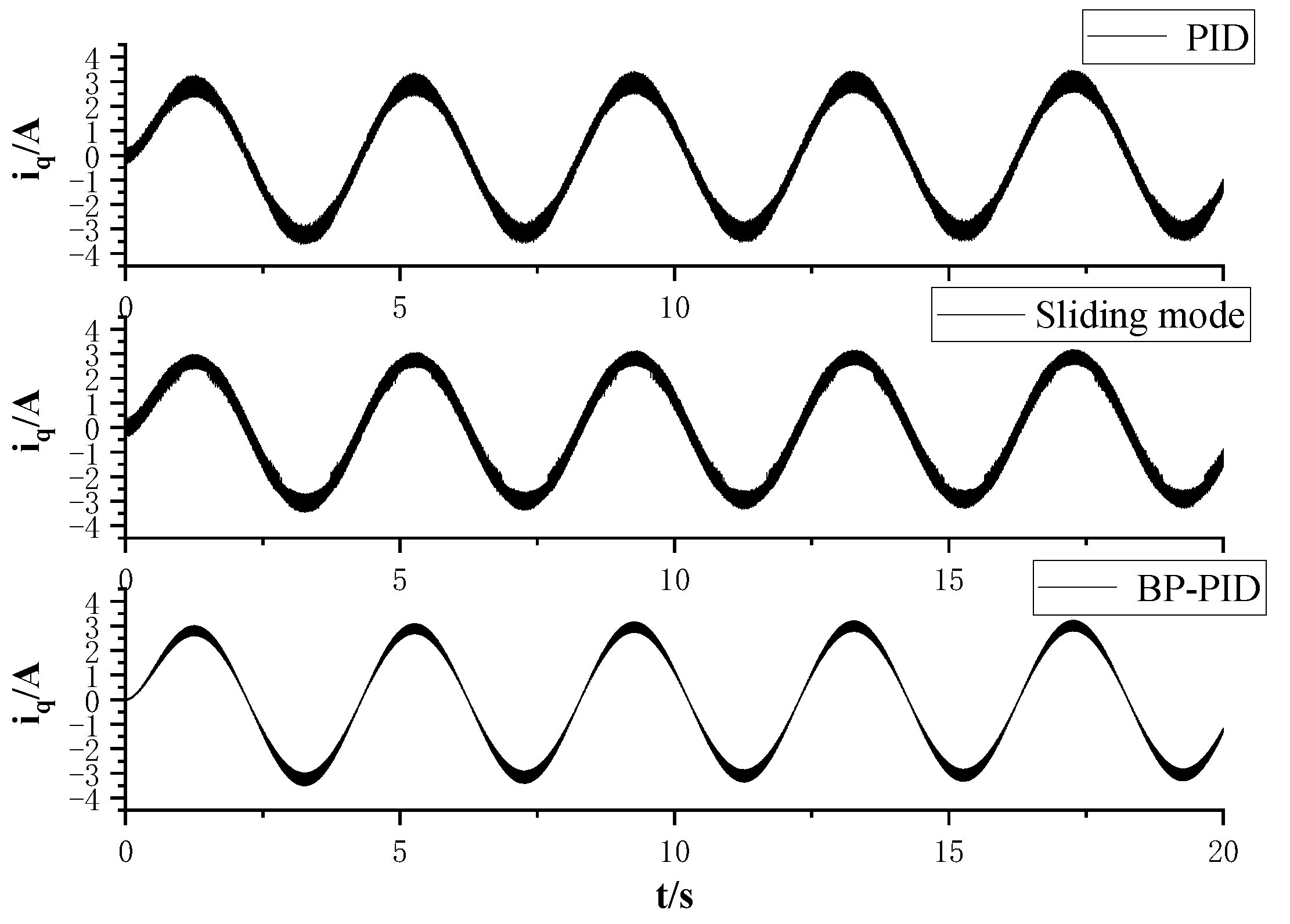
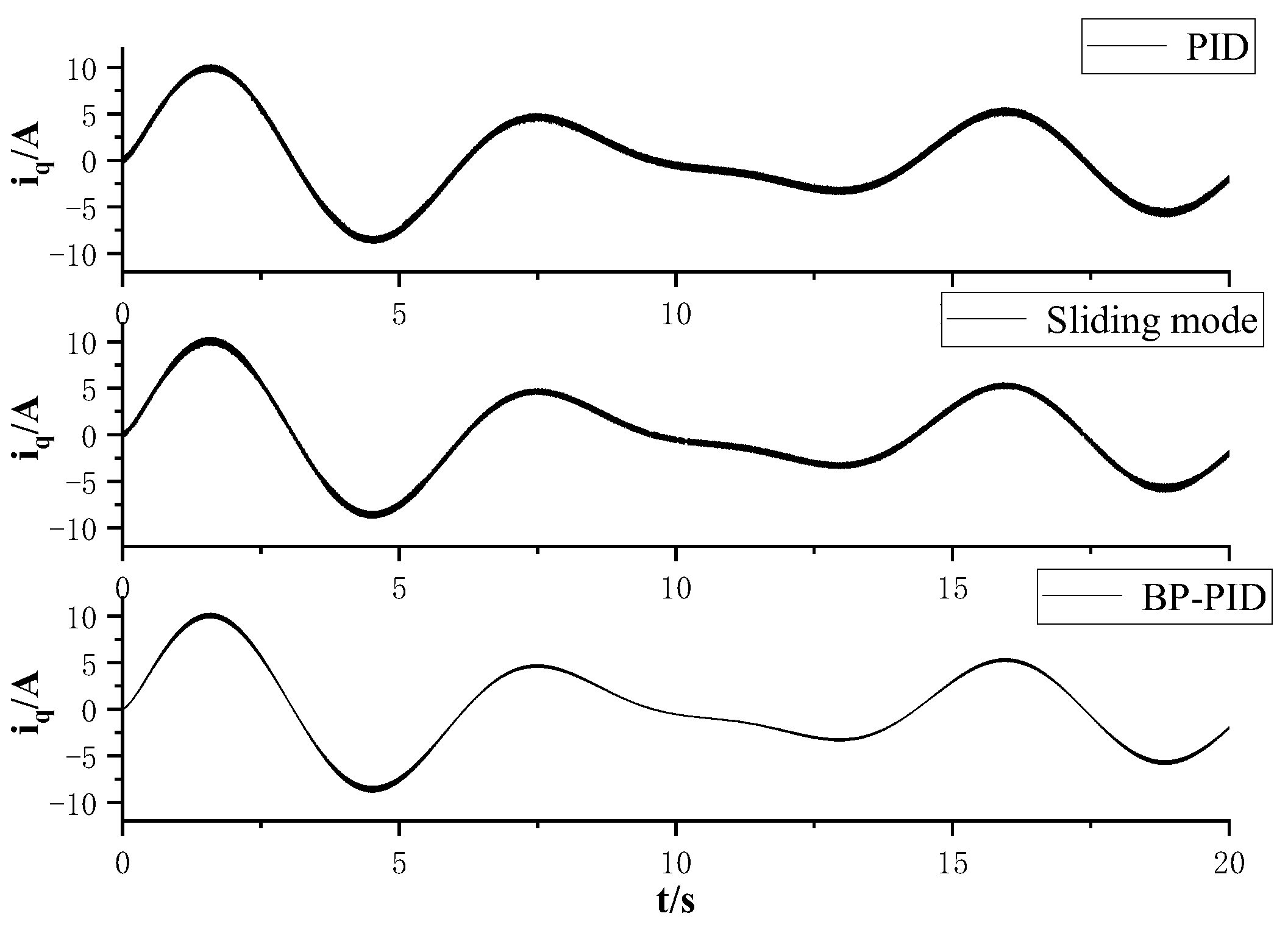
Figure 8 shows the q-axis tracking current under three types of control, and Figure 9 shows the q-axis current tracking error under three types of control. It can be seen that under PID control, the q-axis current waveform has larger ripples, and the error is also relatively large, approximately around 0.6 A. Under sliding mode control, the q-axis tracking current and tracking error show some improvement compared to PID control, with an error of about 0.5 A. However, due to the chattering issue present in sliding mode control, the error does not significantly improve. Compared to PID and sliding mode control [25], it is evident that under BP neural network PID control, the waveform ripple significantly decreases, and the tracking error substantially reduces, with the error reduced to approximately 0.2 A, improving the accuracy of the system’s current tracking.
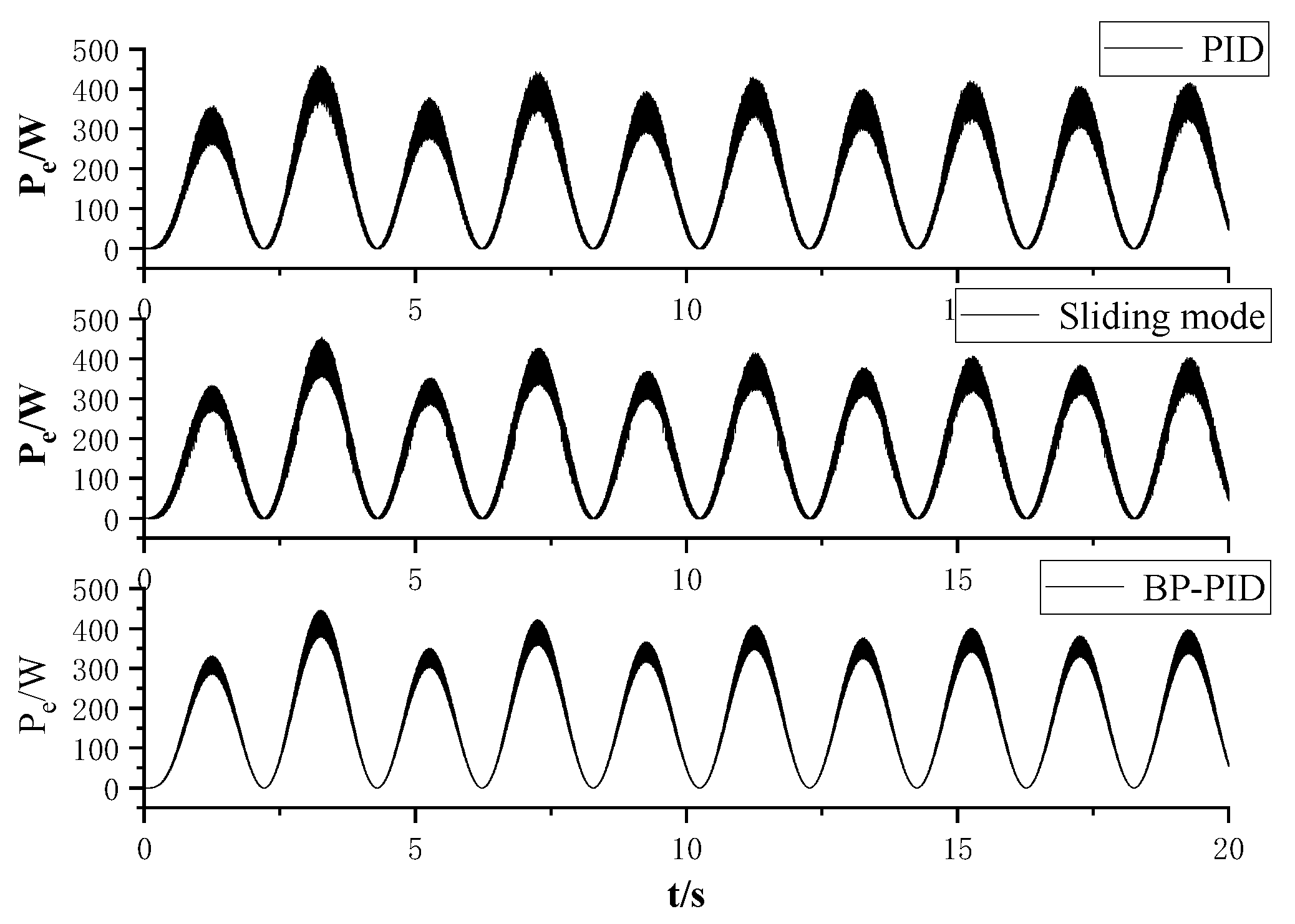
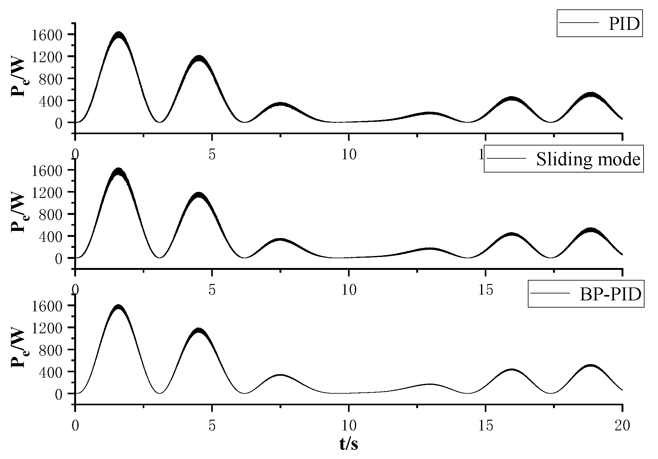
Figure 10 shows the instantaneous power under different controllers. It can be observed that under PID control and sliding mode control, the chattering issue with the q-axis current causes serious fluctuations in instantaneous power, indicating poor system stability. In contrast, the instantaneous power fluctuations are smaller under BP neural network PID control, indicating better system stability. By comparing the q-axis current tracking error under three controllers, it is evident that the q-axis current tracking error is smaller and the accuracy is better under BP neural network PID control.
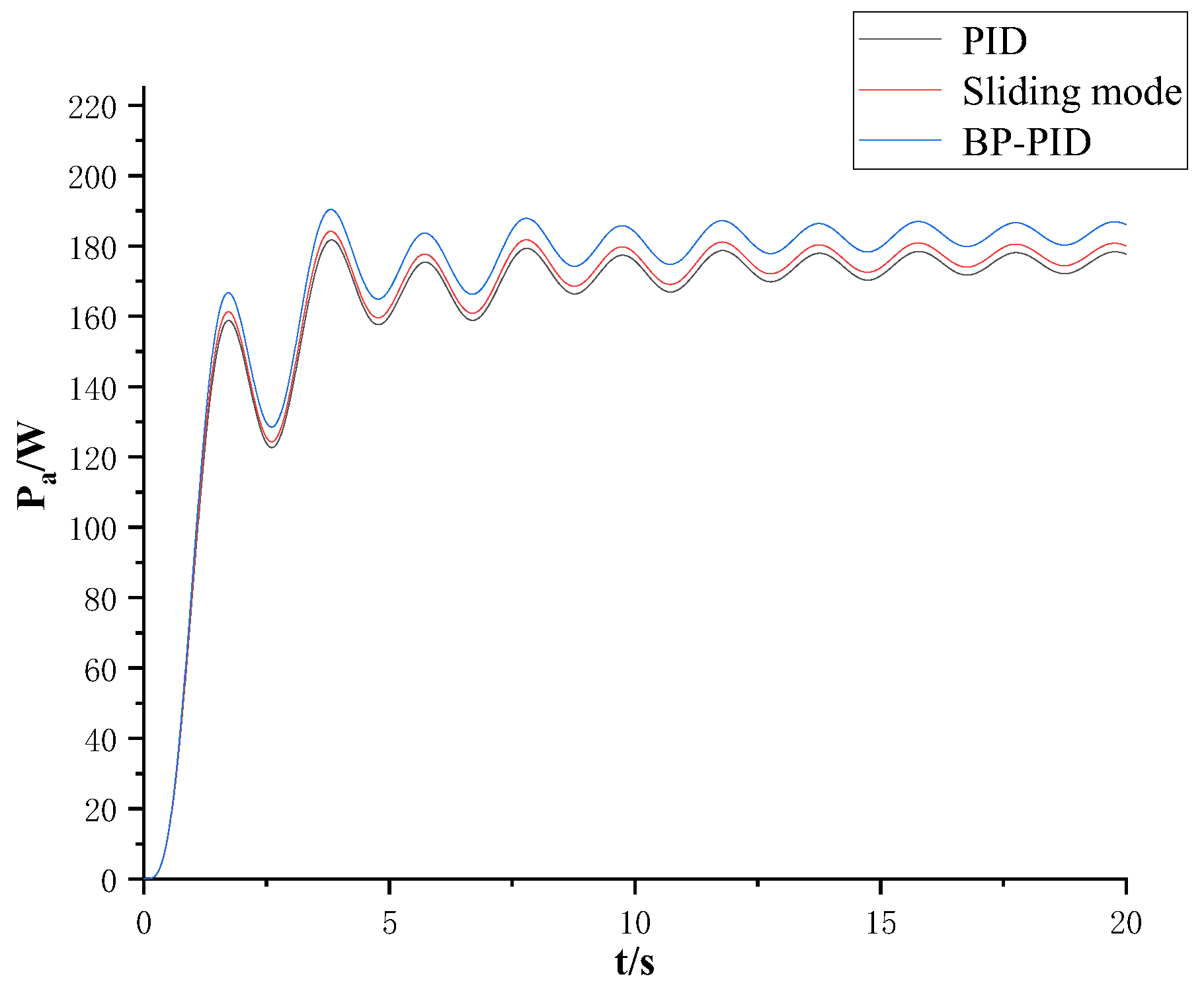
Figure 11 shows the system’s average power under different controllers. As seen in Figure 11, the system’s average output power under BP neural network PID control is approximately 10 W higher than that under the other two controls, which, due to the choice of relatively small parameter values, represents an increase of about 6%.
5.2. Irregular Wave Simulation Analysis
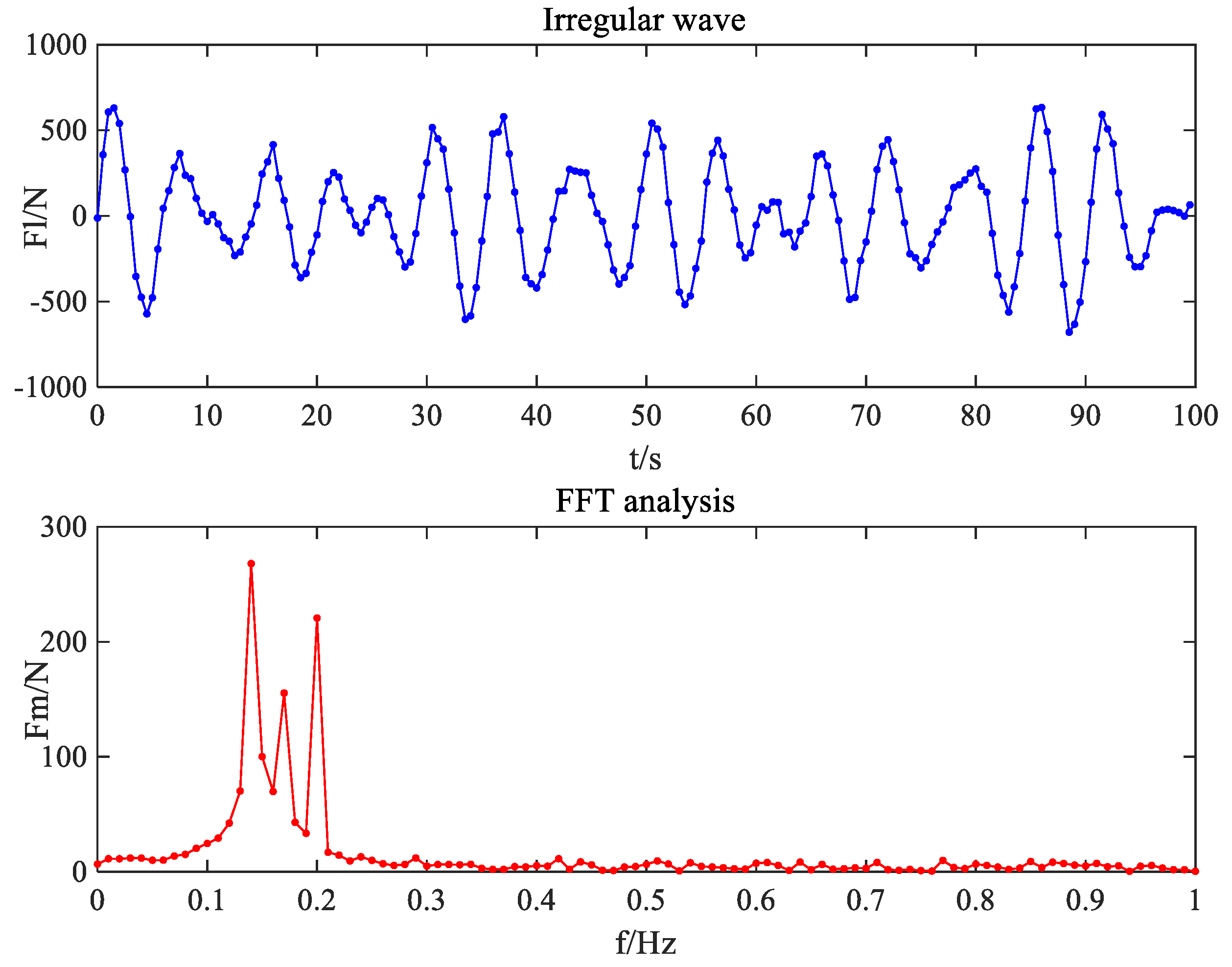
Firstly, a random irregular wave’s waveform is given, followed by the use of simulation software to perform a Fast Fourier Transform (FFT) on the inputted random irregular wave, with a sampling frequency of 2 Hz and a sample count of 200. The inputted irregular wave’s waveform and the resulting FFT spectrum analysis are shown in Figure 12. It can be seen that the irregular wave’s waveform in Figure 12 is composed of three sinusoidal signals of different amplitudes and frequencies and a disturbance signal. The irregular wave’s waveform in Figure 12 is approximately as follows:
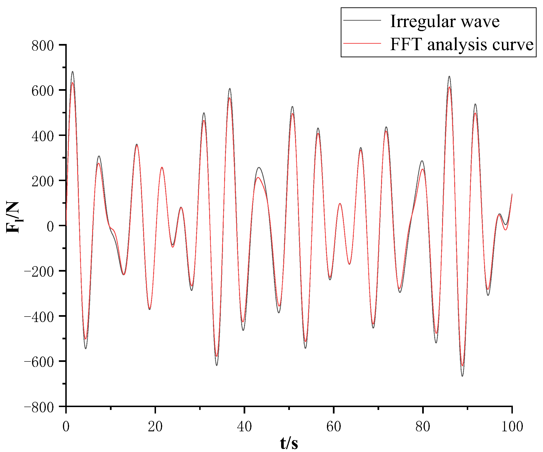
Figure 13 compares the given irregular wave’s waveform with the waveform obtained from FFT analysis. The given irregular wave’s waveform cannot directly serve as the input; in reality, the wave is a nonlinear excitation force. It requires a main frequency estimation method to predict the main frequency of the irregular wave excitation force. The amplitude and frequency obtained after FFT analysis must be compared with the original given irregular waveform to judge the reliability of the main frequency prediction method. According to FFT analysis, the composition of the amplitude and frequency of the irregular wave curve can be compared with the original irregular wave’s waveform. It is evident that the waveform obtained from FFT analysis has a small error compared to the given irregular waveform, making it suitable for analyzing irregular waveforms.
By removing the disturbance signal from Equation (22), the equation for the input excitation force can be obtained. Then, using the principle of superposition, the q-axis reference current is calculated. Figure 14 shows the irregular wave excitation force and the waveform at 300 times speed under BP neural network PID control. It can be observed from the figure that the irregular wave excitation force and speed maintain the same frequency and are essentially in phase, meeting the resonance condition, i.e., the power generation device operates at maximum power.
Figure 15 and Figure 16 show the q-axis tracking current and error under each control. It can be seen that in irregular waves, BP neural network PID control still performs well in tracking the q-axis current, with an error of about 0.2 A, reducing the error by 0.5 A compared to PID control and sliding mode control.
Figure 17 shows the instantaneous power under different controllers in the presence of an irregular excitation force. It can be seen that under PID control and sliding mode control, the instantaneous power has significant ripples in the presence of an irregular excitation force, indicating poor system stability; under BP neural network PID control, the fluctuations are smaller, indicating better stability.
Figure 18 shows the average power of irregular waves. From the figure, it can be seen that the average power difference between PID control and sliding mode control is very small, while BP neural network PID control improves the power compared to the two control algorithms by about 20 W. This indicates that for irregular waves, BP neural network PID control has a better effect on the system’s capture efficiency.
In summary, Table 2 summarizes the advantages of the BP neural network PID control algorithm.
6. Conclusions
This paper proposes a maximum power control system for a direct-drive wave power generation device based on BP neural network PID control combined with Kalman filtering. It calculates the q-axis tracking current for maximum power tracking of the system and conducts a simulation analysis under different controllers. The main research conclusions are as follows:
- Through the simulation analysis comparison, the instantaneous power ripple is significantly reduced under BP neural network PID control compared to PID control and sliding mode control, indicating that the system has better stability under BP neural network PID control.
- Under BP neural network control, the q-axis tracking current error is smaller, reduced by about 0.4 A, improving the system’s stability and accuracy.
- For both regular and irregular waves, the system’s average power is higher under BP neural network PID control, with an average power increase compared to PID and sliding mode control of about 6%, indicating an improvement in the system’s energy capture efficiency.
Author Contributions
Conceptualization, X.F. and H.M.; methodology, X.F. and H.M.; software, formal analysis, and investigation, X.F. and H.M.; data curation, X.F. and H.M.; writing—original draft preparation, X.F. and H.M.; writing—review and editing, X.F. and H.M. All authors have read and agreed to the published version of the manuscript.
Funding
This study was funded by the National Natural Science Foundation of China, grant number 52205271, and the Natural Science Foundation of Jiangsu Province, China, grant number BK20190972.
Institutional Review Board Statement
Not applicable.
Informed Consent Statement
Not applicable.
Data Availability Statement
The original contributions presented in the study are included in the article, further inquiries can be directed to the corresponding author/s.
Conflicts of Interest
The authors declare no conflict of interest.
References
- Shi, H.; Liu, Z. Research progress and development trend of ocean wave energy. Sci. Technol. Rev. 2021, 39, 22–28. [Google Scholar]
- Liu, Y.; Jia, R.; Zhang, J. Research status and development prospect of wave energy generation technology. J. Mar. Technol. 2016, 35, 100–104. [Google Scholar]
- Qu, Q.; He, H.; Li, H. Numerical simulation of swing plate motion response of a floating wave energy generator. Ocean. Eng. 2013, 31, 82–88. [Google Scholar]
- Fang, Z.; Ge, X.; He, K.; Ma, Z.; Fang, J. Design and Research of Pendulum Power Generation Device for unmanned Underwater Vehicle. China Mech. Eng. 2018, 29, 2306–2311. [Google Scholar]
- Krishna, R.; Svensson, O.; Rahm, M.; Kottayil, S.K.; Waters, R.; Leijon, M. Analysis of linear wave power generator model with real sea experimental results. IET Renew. Power Gener. 2013, 7, 574–581. [Google Scholar] [CrossRef]
- Polinder, H.; Damen, M.E.C.; Gardner, F. Linear PM genertor system for wave energy conversion in the AWS. IEEE Trans. Energy Convers. 2004, 19, 583–589. [Google Scholar] [CrossRef]
- Falnes, J. A review of wave-energy extraction. Mar. Struct. 2007, 20, 185–201. [Google Scholar] [CrossRef]
- Ling, H.; Göteman, M.; Mats, L. A Methodology of Modelling a Wave Power System via an Equivalent RLC Circuit. IEEE Trans. Sustain. Energy 2016, 7, 1362–1370. [Google Scholar]
- Yang, J.; Huang, L.; Zhong, W.; Hu, M. Energy tracking control of direct drive Wave Power Generation System. Trans. China Electrotech. Soc. 2017, 32, 22–29. [Google Scholar]
- Lin, Q.; Yang, J.; Cai, H.; Yang, J. MPPT control strategy for direct drive Wave Power Generation System based on sliding mode Control. Electr. Meas. Instrum. 2018, 55, 90–95. [Google Scholar]
- Huang, B.; Yang, J.; Shen, H.; Fan, X. Power optimization control of direct drive wave power generation System based on FFT. Acta Sol. Sin. 2019, 42, 206–213. [Google Scholar]
- Sun, D.; Hou, H.; Wang, L.; Zhai, Z. System Design of Belt Conveyor Hydraulic Tensioning Device Based on BP Neural Network PID Control. Coal Mine Mach. 2020, 41, 16–19. [Google Scholar]
- Yang, J.; Huang, L.; Hu, M. Modeling and control strategy based on energy tracking for direct drive wave energy conversion. In Proceedings of the 19th International Conference on Electrical Machines and Systems (ICEMS), Chiba, Japan, 13–16 November 2016; IEEE: Piscataway, NJ, USA, 2016. [Google Scholar]
- Zhang, M.; Yang, S.; He, H.; Zhang, J.; Li, H. Modeling and simulation analysis of array raft wave energy generation device. Ocean. Eng. 2017, 35, 83–88. [Google Scholar]
- Yang, Z.; Zhang, T.; Duan, H.; Zhu, M.; Shao, Y. Comparative study on motion simulation methods of cylindrical buoy under wave action. J. Unmanned Undersea Syst. 2018, 26, 291–297. [Google Scholar]
- Fan, X.; Wang, C.; Zhu, Z.; Meng, H. Design and Analysis of a High Power Density Permanent Magnet Linear Generator for Direct-drive Wave Power Generation. Actuators 2022, 11, 327. [Google Scholar] [CrossRef]
- Dai, L.; Li, Y.; You, Q.; Wei, H.; Zhang, Y. Chaotic Optimal Control of Permanent Magnet Synchronous Motor based on LMI Algorithm. J. Unmanned Undersea Syst. 2021, 29, 293–298. [Google Scholar]
- Tan, C.; Ren, H.; Li, B.; Lu, J.; Li, D.; Tao, W. Design and analysis of a novel cascade control algorithm for braking-by-wire system based on electromagnetic direct-drive valves. J. Frankl. Inst. 2022, 359, 8497–8521. [Google Scholar] [CrossRef]
- Yang, J.; Huang, B.; Shen, H.; Xie, D.; Xiong, F.; Lu, S.; Chen, H. EKF based fuzzy PI controlled speed sensorless power optimal control of a direct drive power system. IEEE Access 2019, 7, 61610–61619. [Google Scholar] [CrossRef]
- Mendonca, H.; Martinez, S. A Resistance Emulation Approach to Optimize the Wave Energy Harvesting for a Direct Drive Point Absorber. IEEE Trans. Sustain. Energy 2015, 7, 3–11. [Google Scholar] [CrossRef]
- Kang, Q.; Xiao, X.; Nie, Z.; Huang, L. Optimization Control Strategy for Output Power of Direct Drive Wave Power Generation System. Power Syst. Autom. 2013, 37, 24–29. [Google Scholar]
- Huang, J.; Yang, J.; Cai, H.; Lin, Q. Active disturbance rejection power optimization control of direct drive wave power generation system based on WFT. J. Renew. Energy 2021, 39, 1271–1277. [Google Scholar]
- Hao, J.; Xie, Z.; Chen, L.; Wu, Y. Research on PID Control Algorithm of Magnetic Bearing Based on BP Neural Network. Mach. Build. Autom. 2021, 2, 127–130. [Google Scholar]
- Huang, B.; Yang, J.; Lu, S.; Chen, H. Backward step optimal power tracking control for wave power generation system based on Kalman filter. J. Renew. Energy 2020, 38, 347–352. [Google Scholar]
- Lu, Y.; Tan, C.; Ge, W.; Li, B.; Lu, J. Improved sliding mode-active disturbance rejection control of electromagnetic linear actuator for direct-drive system. Actuators 2021, 10, 138. [Google Scholar] [CrossRef]
Figure 1.
Principle diagram of direct-drive wave power system.

Figure 2.
RLC equivalent circuit diagram.

Figure 3.
Diagram of structure of BP neural network.

Figure 4.
Structure diagram of BP neural network PID controller.

Figure 5.
Controller flow chart.

Figure 6.
Diagram of structure of power generation system model.

Figure 7.
Regular wave excitation force and 300 times speed.

Figure 8.
Q-axis tracking current under three controllers.

Figure 9.
Q-axis current tracking error under three controllers.

Figure 10.
Diagram of instantaneous power under different controllers.

Figure 11.
Diagram of average power under different controllers.

Figure 12.
Diagram of irregular wave’s waveform.

Figure 13.
Irregular wave’s waveform contrast.

Figure 14.
The irregular wave excitation force at 300 times the speed of the waveform.

Figure 15.
Three controlled Q-axis tracking currents for irregular waves.

Figure 16.
Q-axis current tracking error of three kinds of controllers for irregular waves.

Figure 17.
Diagram of instantaneous power of irregular waves.

Figure 18.
Diagram of average power of irregular waves.


Table 1.
Simulation parameter settings.
| Variable | Value | Variable | Value |
|---|---|---|---|
| Ld | 0.0114 H | M | 100 kg |
| Lq | 0.0114 H | m | 50 kg |
| r | 1 Ω | 210 | |
| n | 4 | 61.5 | |
| 0.05 m | 300 N | ||
| 0.52 Wb | 0.5 π |
Table 2.
Comparison of control algorithm results.
| Variable | Control Algorithm | Q-Axis Current Tracking Error | Power Boost |
|---|---|---|---|
| Regular wave | PID | 0.6 A | -- |
| Sliding mode | 0.5 A | 1.3% | |
| BP—PID | 0.2 A | 6% | |
| Irregular wave | PID | 0.5 A | -- |
| Sliding mode | 0.5 A | 0.7% | |
| BP-PID | 0.2 A | 2.5% |
Disclaimer/Publisher’s Note: The statements, opinions and data contained in all publications are solely those of the individual author(s) and contributor(s) and not of MDPI and/or the editor(s). MDPI and/or the editor(s) disclaim responsibility for any injury to people or property resulting from any ideas, methods, instructions or products referred to in the content. |
© 2024 by the authors. Licensee MDPI, Basel, Switzerland. This article is an open access article distributed under the terms and conditions of the Creative Commons Attribution (CC BY) license (https://creativecommons.org/licenses/by/4.0/).
Share and Cite
MDPI and ACS Style
Fan, X.; Meng, H. Research on Maximum Power Control of Direct-Drive Wave Power Generation Device Based on BP Neural Network PID Method. Actuators 2024, 13, 159. https://doi.org/10.3390/act13050159
AMA Style
Fan X, Meng H. Research on Maximum Power Control of Direct-Drive Wave Power Generation Device Based on BP Neural Network PID Method. Actuators. 2024; 13(5):159. https://doi.org/10.3390/act13050159
Chicago/Turabian StyleFan, Xinyu, and Hao Meng. 2024. "Research on Maximum Power Control of Direct-Drive Wave Power Generation Device Based on BP Neural Network PID Method" Actuators 13, no. 5: 159. https://doi.org/10.3390/act13050159
Note that from the first issue of 2016, this journal uses article numbers instead of page numbers. See further details here.