Article

Car Soundproof Improvement through an SMA Adaptive System †

1
Adaptive Structures Division, CIRA—Centro Italiano Ricerche Aerospaziali, 81043 Capua, Italy
2
Global Innovation, Centro Ricerche Fiat, 80038 Pomigliano d’Arco (NA), Italy
*
Author to whom correspondence should be addressed.
This paper is an extension version of the conference paper: Ameduri, S.; Brindisi, A.; Ciminello, M.; Concilio, A.; Quaranta, V.; Brandizzi, M. An SMA Seal System for Enhanced Door Soundproof Performance: Design, Prototyping and Testing. In Proceedings of 16th International Conference on New Actuators, Bremen, Germany, 25–27 June 2018.
Actuators 2018, 7(4), 88; https://doi.org/10.3390/act7040088
Submission received: 29 October 2018 / Revised: 7 December 2018 / Accepted: 8 December 2018 / Published: 13 December 2018
(This article belongs to the Special Issue Actuators Based on Shape Memory Alloys)

Abstract

:
The work at hand focuses on an adaptive system aimed at improving the soundproof performance of car door seals at specific regimes (cruise), without interfering with the conventional opening and closing operations. The idea addresses the necessity of increasing seal effectiveness, jeopardized by aerodynamic actions that strengthen as the speed increases, generating a growing pressure difference between the internal and the external field in the direction of opening the door, and then deteriorating the acoustic insulation. An original expansion mechanism driven by a shape memory alloy (SMA) wire was integrated within the seal cavity to reduce that effect. The smart material was activated (heated) by using the Joule effect; its compactness contributed to the realization of a highly-integrable and modular system (expanding cells). In this paper, the system development process is described together with the verification and validation activity, aimed at proving the functionality of the realized device. Starting from industrial requirements, a suitable solution was identified by considering the basic phenomenon principle and the allowable design parameters. The envisaged system was designed and its executive digital mock-up (CAD, computer-aided design) was released. Prototyping and laboratory tests showed the reliability of the developed numerical models and validated the associated predictions. Finally, the system was integrated within the reference car. To demonstrate the insulation effect, the experimental campaign was carried out in an anechoic room, achieving significant results on the concept value.

1. Introduction

A critical aspect the automotive industry is currently facing is represented by the abatement of the environmental impact of vehicles, in compliance with increasingly stricter regulations that include, among others, chemical and acoustic pollution aspects [1].
With the aim of matching environmental issues and, at the same time, consolidating their role in the market, automotive companies are turning their attention to new technologies characterized by an adequate level of maturity to assure a competitive and quick diffusion of their products. According to this trend, the car of the future will be electrified, autonomous, shared, connected, and updated yearly [2].
Within that scenario, a critical role is played by the possibility of reducing weight [3], saving energy [4], and abating chemical [5] and acoustic [6] emissions. To achieve those objectives, many subsystems are potentially involved: Engines, bodyworks, gearboxes, cockpits, control units, seals (insulation for sound, water, etc.), and many others.
The growing market interest for the interior comfort, targeting customers’ satisfaction, and the increasing competence that the complete value chain of the technological research in Europe has been developing on that topic has led to many research programs starting in the last decades, featuring a close cooperation among academies, research centers, SME (Small and Medium Enterprises), and large industries. The knowledge created in that framework has given rise to an impressive amount of scientific publications. Among the most relevant, the following projects seem worthy of being cited: “Integrated Solutions for Noise and Vibration Control in Vehicles” (CO2NTROL), which aimed to explore the potentiality of integrated architectures for vibroacoustic attenuation, to improve fuel efficiency, and to reduce environmental impact [7]; “Intelligent Materials for Active Noise Reduction” (InMAR), focusing on novel concepts and innovative materials to improve automotive comfort and mitigate acoustic emissions [8]; and “European Competitiveness in Commercial Hybrid and Automotive Powertrains” (ECOCHAMPS), on cars’ and commercial vehicles’ hybrid powertrain efficiency improvement, including cost savings and reduced emissions [9]. Scientific and industrial research have been focused on many aspects, such as:
  • The assessment of predictive models and design strategies oriented to noise and vibration (like dedicated models and development processes reported by Panda in [10], or the “virtual car” for sound and vibration prediction proposed by Genuit and Bray [11]);
  • the measurement of radiated sound and related environmental impact (among others, the extensive study on the German railway network sound sources, Werning et al. [12], and the assessment of dedicated tools to measure the noise radiated by specific automotive components, Razak et al. [13]);
  • the development and maturation of innovative materials with excellent damping and insulation properties (e.g., shape memory alloys, Duffy et al. [14], and magneto-strictive materials, Davino et al. [15]); and
  • the development and integration of dedicated noise and vibration control strategies (f.i., embedded piezoelectric-based solutions developed by Bein et al. in the abovementioned CO2NTROL project [16], piezo shunted resonators assessed by Liao and Sodano [17] or Ciminello et al. [18], SMA-based architectures for dynamic structural response modulation introduced by Ameduri et al. [19]).
Within this scenario, SMA technology shows great potential, and is currently the object of a wide research effort worldwide, ranging from modeling to implementation aspects. To cite some examples, Bettini et al. [20] described processes to include SMA wires within a carbon-fiber plate to give it adaptive properties; and Spaggiari and Dragoni [21] presented an original model for special constant-force, long-stroke SMA springs. General design issues concerning SMA-based devices were faced by Reynaerts and Brussel [22]. Some perspectives in the use of SMA as basic elements of miniaturized actuators (MEMS) were reported by Nespoli et al. [23]. Ishii and Ting [24] formulated an engineering approach to support designers of shape changing, SMA-based actuators in evaluating and selecting the most suitable type of mechanism for a given problem. Indeed, SMA-based devices have been applied in many engineering fields, ranging from medical (e.g., the OmniPod System patch pump for insulin therapy [25]), to automotive (f.i., pneumatic valves for lumbar support in car seats [26] or mirror actuators [27]), optics (as for image stabilization, [28]), and aerospace areas (like the Space Pin-Puller and Frangibolt [29]) A critical role in SMA applications is played by fatigue aspects: Recently, many companies introduced devices able to work for about one million cycles at operational stresses (f.i., SmartFlex Springs and Wires [30]).
The “Low Noise” project (2012–2015), funded by the Italian Ministry of Education and Research, was conceived within that scenario, and aimed to develop advanced solutions for reducing noise and vibration levels in cars through novel and sustainable materials, minimizing weight impact and other effects that would have caused, in turn, a worsening of consumption and emissions performance. In detail, the activities focused on acoustic sources that would be dominant in electric or hybrid vehicles, standing the lack of combustion motors’ noise.
The work at hand describes the activities directed to develop an SMA-based active seals system and demonstrate its effectiveness in assuring established sound insulation levels. This paper follows a publication by the same authors [31] that gave a preliminary overview of the developed research. This version reports a detailed description of that investigation, introducing unpublished aspects of numerical finite element (FE) simulations and experimental SMA system characterization, and providing an extended description of the assessed device and its operating mode.
Concerning the referred application, classical technologies were hardly applicable because of the reduced room. Furthermore, according to the actual layout, the device should have been deployed along several meters; thus, for instance, alternative technologies based on MEMS were not considered, having considered the costs and complexity of those choices. On the other hand, the automotive industry has matured, with remarkable experience in the use of SMA technology that presents fantastic advantages in terms of compactness, energy density, and transmittable forces and strains [32]. The authors themselves have grown a remarkable know-how in the use of SMA-based devices, developed and proved in many projects and works [33,34,35].
The articles introduce at first the industrial requirements issued by the FCA (Fiat Chrysler Automobiles) Research Centre, following which the adaptive system specifications were generated. A trade off analysis was then performed, leading to the identification of the technology solution for the defined problem, in the form of an axial expanding cell activated by a longitudinally contracting SMA wire. Design and modelling tasks allowed the definition of the system features (like size, materials, and so on), and prediction of its operational performance (generated radial force, needed power supply, etc.). The executive parameters were assessed in the subsequent prototyping phase. Finally, an experimental validation campaign was arranged to verify the effective capability of the realized SMA-based system to produce the desired insulation improvement on an actual car, through direct measurements of the sound transmission reduction within a semi-anechoic chamber.

2. Seal Adhesion Problem and System Specifications

Static aerodynamic loads acting on the wet car surface cause soundproof performance loss of the door seals. In fact, the specific car geometry produces and magnifies a lateral depression pushing the doors from the internal, reducing the seal adhesion strength. This phenomenon is schematized in Figure 1; a dedicated computational fluid dynamics (CFD) analysis showed a significant vertical displacement field with respect to the door surface, with some local maxima at its edges. Figure 2 (left) illustrates an example of such translations at the driver’s door, as predicted by a FE analysis. Sealing performance depends on the adhesion effectiveness, whose resultant (lift) is expressed as a function of the clearance, herein intended as the net distance between the door and the car cabin frame. Figure 2 (right) provides an example of this function, obtained through a non-linear FE computation that considered the sealing compression. In that same plot, three regions are indicated: (1) Open door; (2) door closed, nominal condition; (3) effect of additional compression due to excessive tightening of the door. Dashed boxes represent experienced operating conditions and, to some extent, represent allowed tolerance. When clearance increases following the aerodynamic actions effect, that gap must be recovered to restore the rated soundproof performance. A solution is to expand the seals so to retrieve the nominal pattern.
Both the very limited space and the need to avoid interferences with door opening and closing operations make SMA actuators good candidates for realizing such devices. They usually present further interesting properties for industrial applications, like compactness, installability, and ease of use. Moreover, the monolithic or quasi-monolithic nature of SMA-based systems leads to advantages in terms of reliability within the established range of fatigue aspects.
System automotive requirements may be summarized as following:
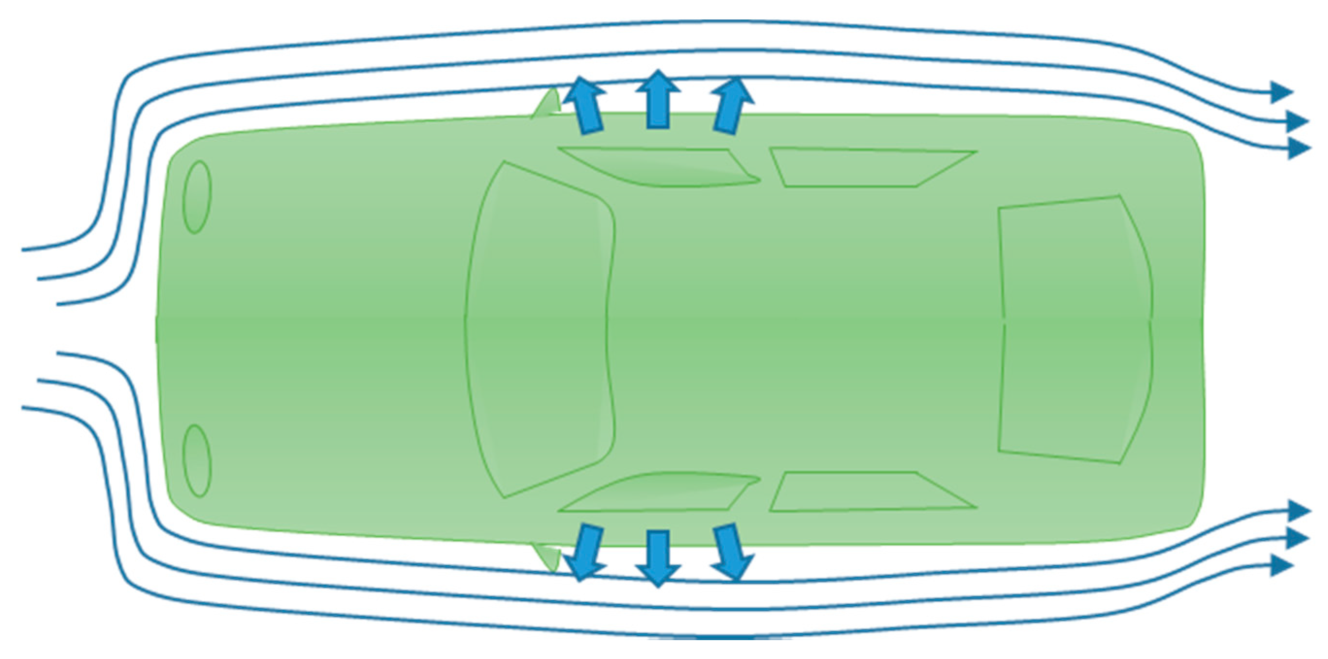
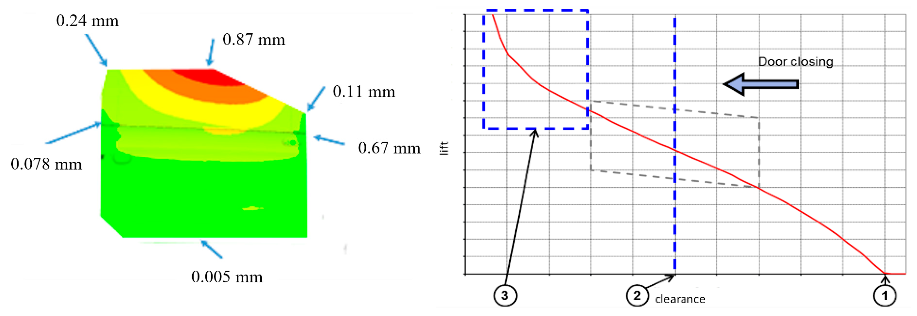
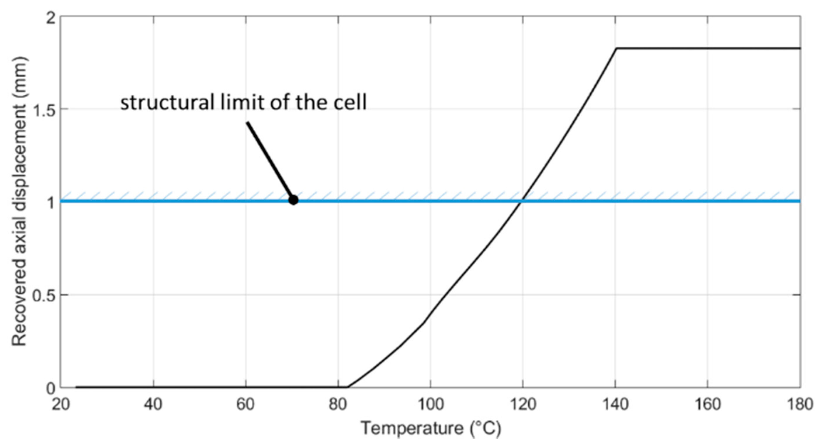
  • Seals gap should not exceed 1.0 mm (by engineering specs, derived from design constraints); in turn, as aerodynamic action is considered, this constraint implies the gap to be retrieved is lower than 2 mm;
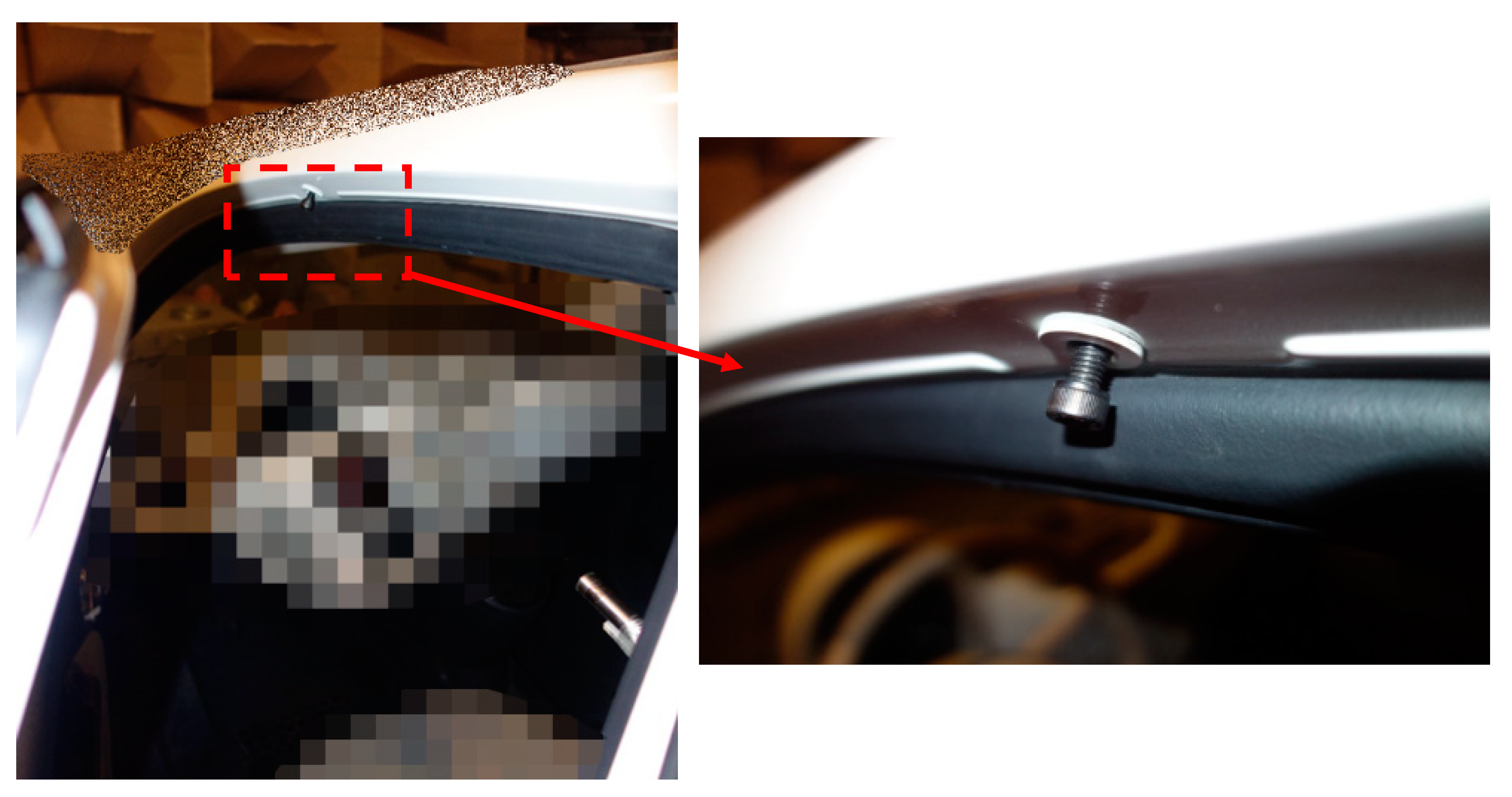
  • the main interest zone, as usual for this kind of problems, was at the forward top corner edge of the two front doors, Figure 2;
  • to be appreciable, SPL abatement should be higher than 3 dB over the frequency band of interest;
  • the temperature operational range should be considered between −50 °C and +80 °C;
  • the proposed system should be designed to be turned on during high-speed cruise segments only; its full activation should be completed within 1 s;
  • the electrical and thermal insulation should be ensured between the SMA system and the relaxed seal; and
  • the power consumption should not exceed 5 W per door, according to standards for such kinds of additional systems, commonly adopted on the car class herein considered.

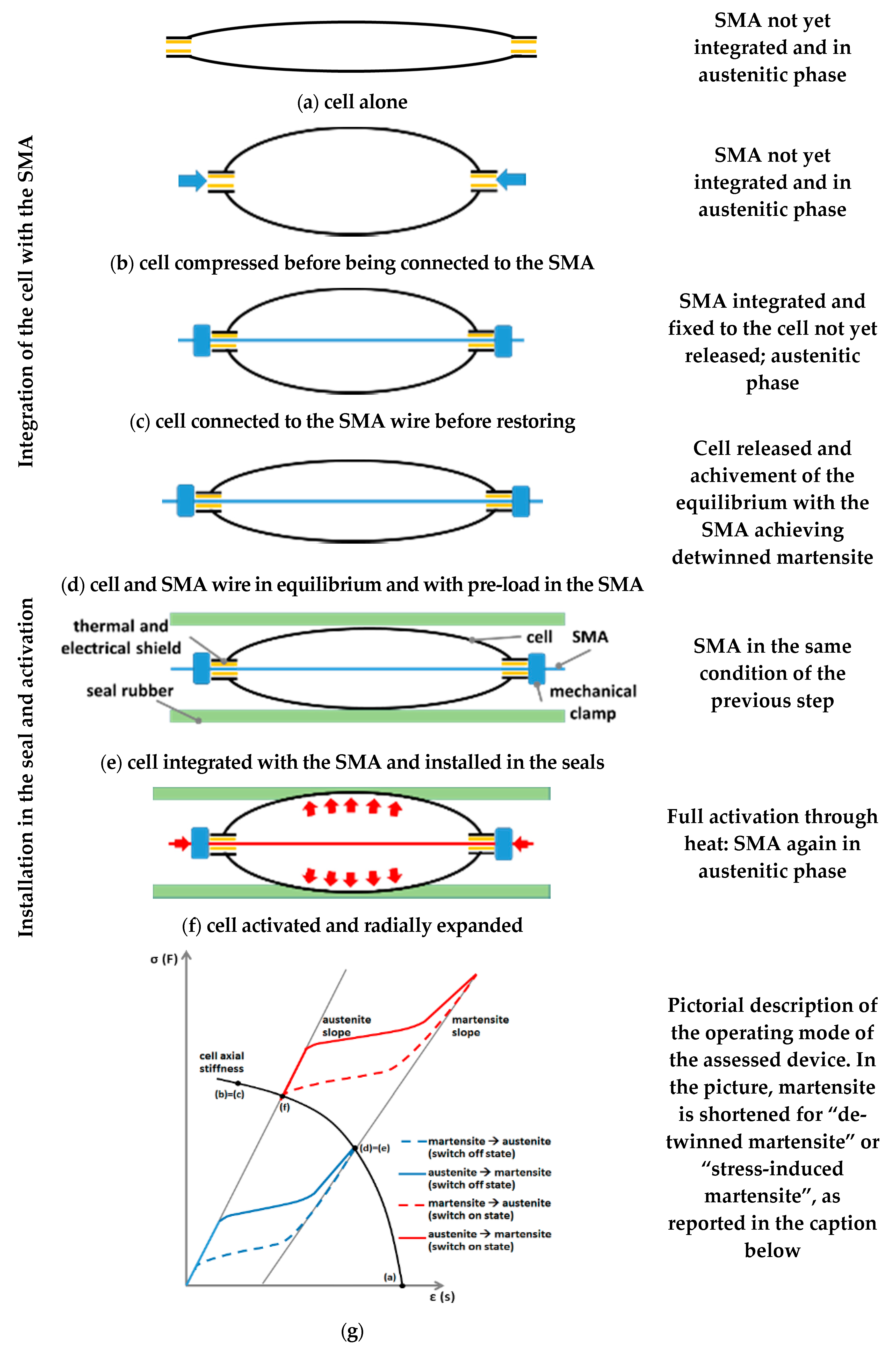
3. Concept, Integration, and Working Phases

The presented concept aimed at expanding the seal (main function) to improve its adhesion to the car door and the cabin frame. The system was made of three main components:
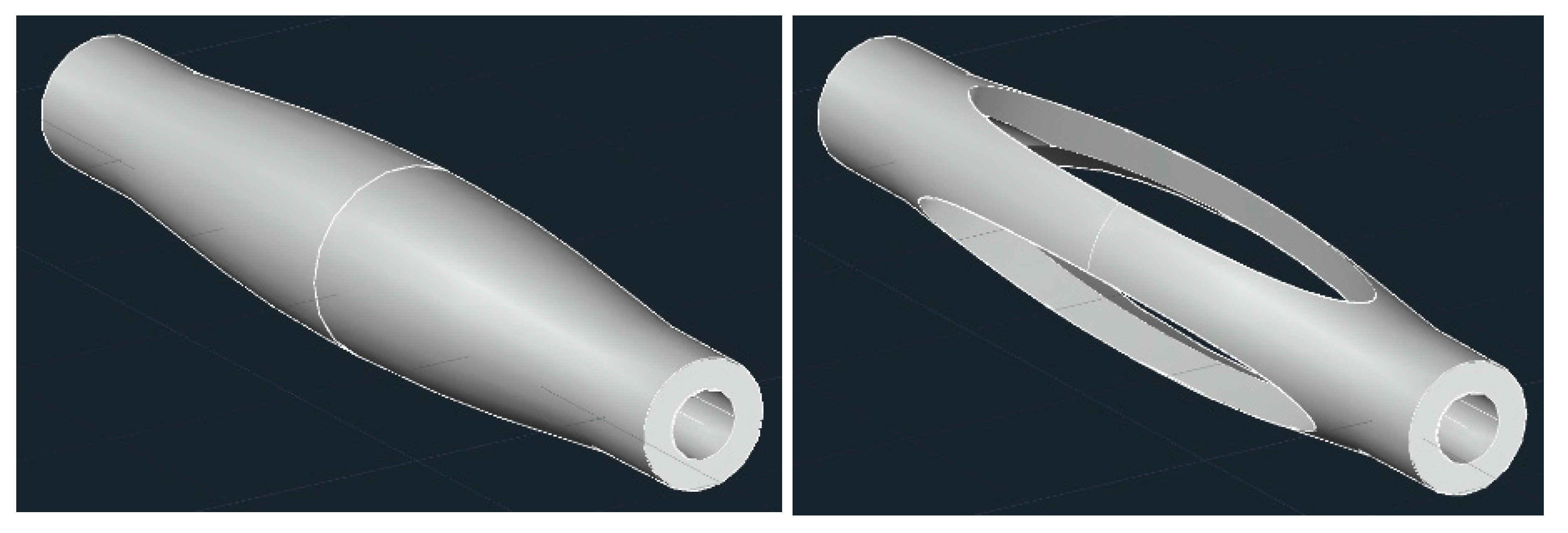
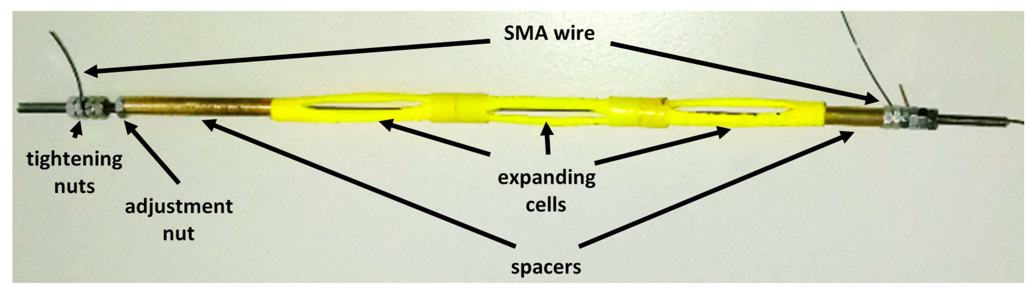
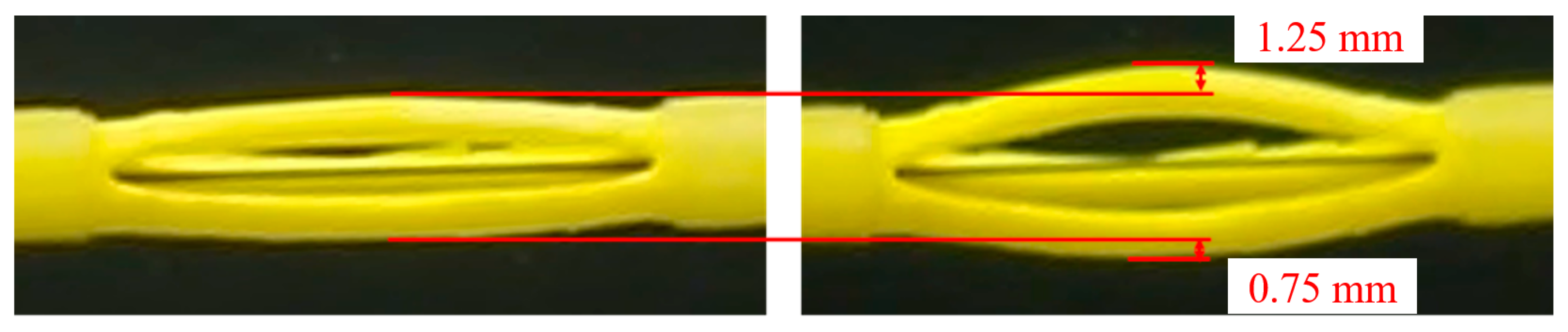
  • A shell-like mechanical structure (“the cell”): A device that hosted a longitudinal SMA active element inside, converting its axial action into transversal displacements with the effect of pushing the seal against the door and its frame. Such a component, which was slender ellipsoid shaped, was deployed within the seal, taking advantage of its natural cavity;
  • the SMA actuator, a pre-stressed wire, linked to the cell axial extremities and equilibrated by its elastic reaction. When heated by using the Joule effect, the wire shrunk (strain recovery) and compressed the cell longitudinally, inducing in turn a transversal expansion (something similar to the Poisson’s effect); and
  • mechanical, thermal, and electrical interfaces: They assured effective mechanical transmission between the wire and the cell, provided a thermal shield between the SMA hot surface, and the cell and the seal rubber, respectively, and limited electrical dispersions.
Figure 3 illustrates the cell system operating mode and its integration phases. The cell structure was initially compressed as it passed from one state (a, unloaded) to the next state (b, pre-stressed). At that stage, a non-stressed, full-austenite SMA wire was inserted within the cell skeleton and constrained at the longitudinal edges (c). The system was then released, achieving its elastic equilibrium (d). The system was designed (stress levels and wire consistence) so that a full transition from austenite to martensite was attained. Because this process phase transformation was stress-driven, stress-induced martensite was obtained or, following the classical nomenclature, de-twinned martensite was achieved (unlike what would have been realized by thermal-driven processes—cooling in this case—that instead would have given rise to twinned martensite). It is worth remarking that SMA wire reached a full de-twinned martensite state in (d) because its properties and the assigned structural pre-stress in (b) were compatible to run all the transformation curve until the phase change was completed (Martensite finish stress, σMf, at the reference temperature). At this point, the cell was inserted within the seal hollow (e) and was ready to operate by heating (full austenite recovery—provided an adequate temperature was reached at the assigned stress levels). The wire shrunk and the cell expanded (f). In this case, there are not distinguished effects between a thermal-driven and a stress-driven transformation.
Representative points of the described phases (a → f) are placed along the stress-strain SMA diagram in Figure 3g. In that graph, SMA characteristic curves are reported at room (blue lines) and a given temperature (red lines) high enough to enable a complete phase transformation (de-twinned martensite to austenite, d,e → f). In Figure 3g, another line is reported, representing the elastic cell longitudinal stress-strain characteristics (applied axial force vs produced axial strain). Intersections of that curve with the SMA characteristic curves identify equilibrium states occurring during the cell installation and its operating phases. So, an unloaded cell is in state (a). After compression, it moves to state (b) when a SMA wire is installed (c). Cell and SMA elastic forces compensate and move the operation point to a new state, (d). In this new configuration, SMA internal stress grows and, if the system was well sized, a full stress-driven martensite state (de-twinned martensite) is achieved. In that condition, the system is installed into the seal and is ready to work. As SMA wire is heated, the operation point moves along the elastic line, from full de-twinned martensite to full austenite state, as a sufficient temperature is reached by using the Joule effect.

4. System Design

The selected design approach allowed facing the cell and SMA wire design, separately. In detail, cell material and geometry choice were driven by the following needs:
  • Assuring full integrability within the hollowed seal, in both on and off states;
  • guaranteeing an extended contact area with the seal to maximize interactions and distribute the load uniformly;
  • establishing a sufficient length to reduce interaction losses and minimize side effects at the connection with the SMA-wire; and
  • keeping the stress and strain levels under certain thresholds to mitigate fatigue problems.

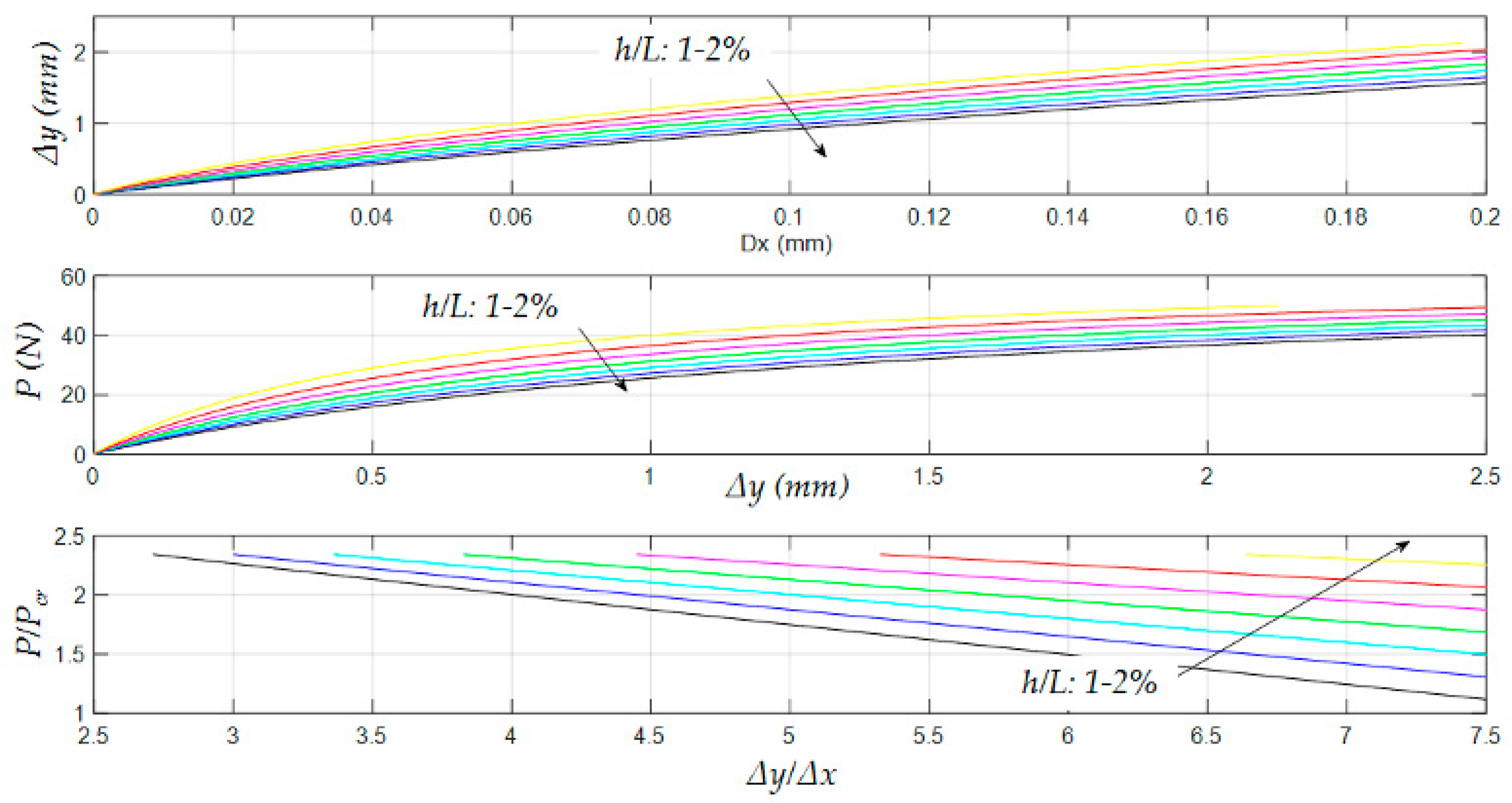
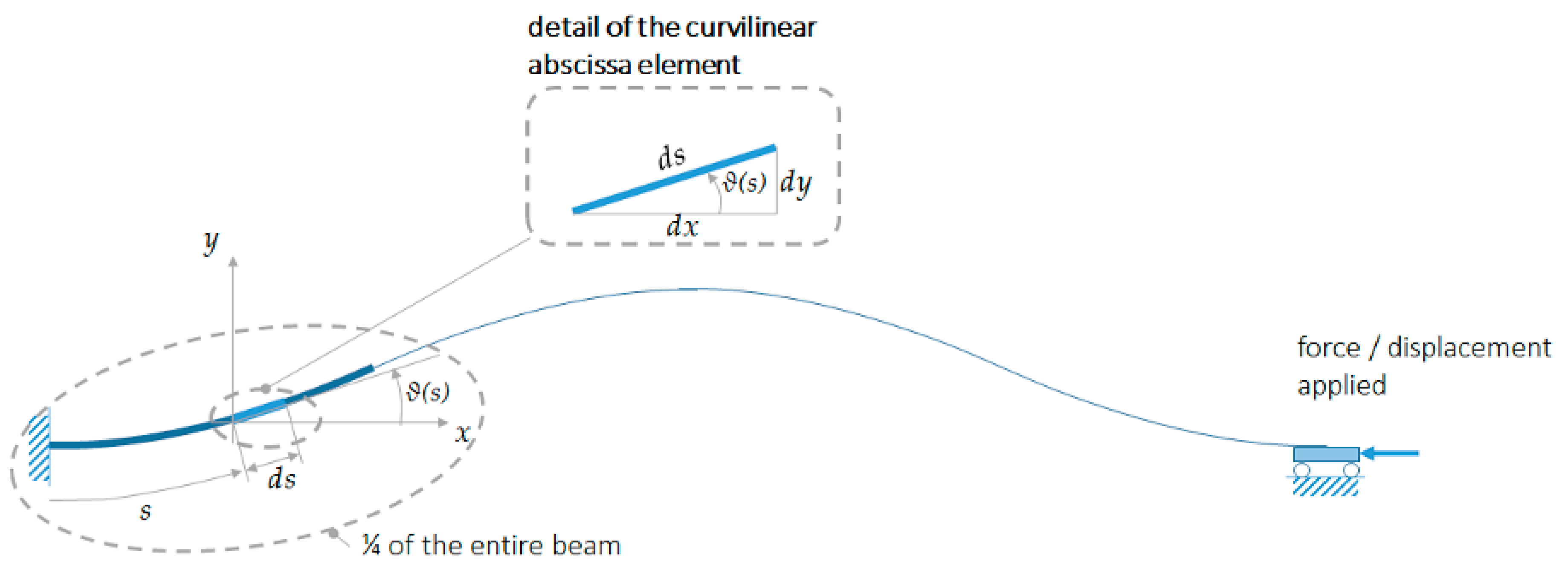
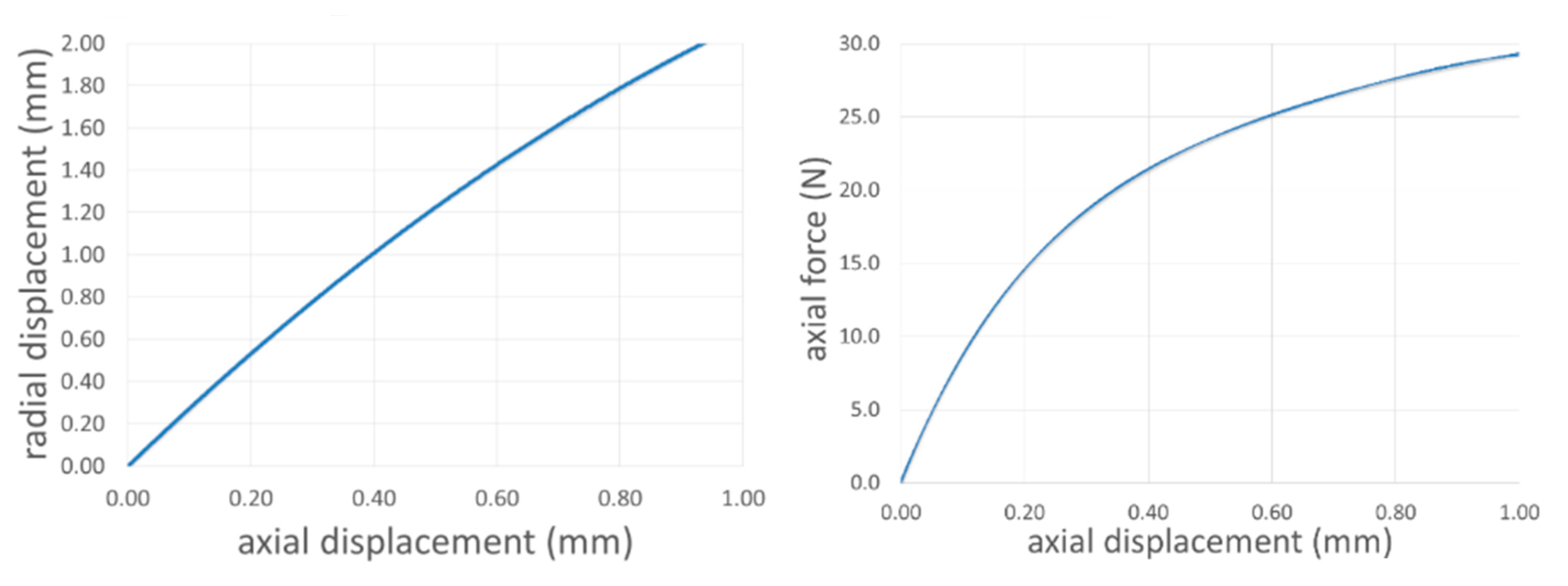
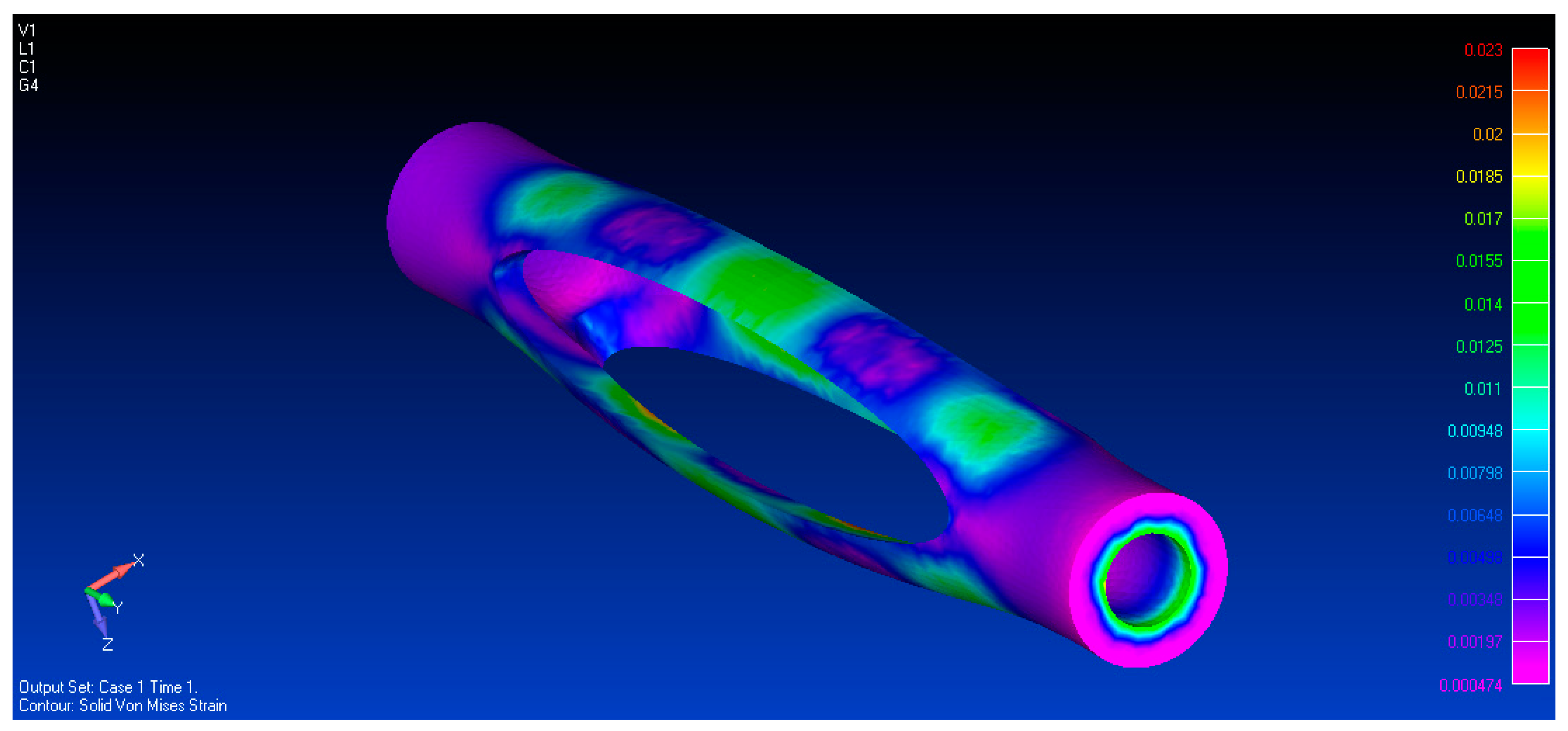
4.1. Cell Modelling and Sizing

Titanium alloy and plastic ABS (Acrylonitrile Butadiene Styrene) materials were considered in view of manufacturing the device by Additive Layer Manufacturing (ALM) processes. However, due to the high stiffness of a typical metal structure and the consequent necessity of reducing the size of the cell architectural parameters beyond acceptable operation limits, plastic ABS materials were finally preferred. The cell was designed with an ellipsoidal shape, optimized to magnify its expansion characteristics. The final outline ensured a good flexibility, producing sufficient deformations after the application of limited stress levels. Longitudinal slits were dug in the original configuration (Figure 4, left) to enhance deformability and improve heat diffusion, creating a sort of three-arm arrangement (Figure 4, right). Such a layout proved to secure suitable contacts with both the door ring and the car body frame for arbitrary angular rotations (barely controllable in the installation phase) within the seal cavity.
In the established design process, arm length, cross section area (thickness and width), and initial curvature were considered. The SMA-structural model described in [36] was implemented on a reduced schematic made of a single arm and the active wire. The numerical representation considered the structural element as a constant cross-section beam, shaped like a sinusoid, as shown in Figure 5.
Its slope, ϑ0(s), was set in the range [0–π]. The local slope, ϑ(s), under an axial load, P, could be obtained numerically by integrating the nonlinear beam equation [37] vs the curvilinear abscissa, s:
E I ( d 2 ϑ d s 2 d 2 ϑ 0 d s 2 ) = P sin ϑ
Holding small displacements hypothesis and considering the problem symmetry, the equation above could be integrated over a quarter of the reference domain. The following boundary conditions were assumed:
  • ϑ ( 0 ) = 0 ; (clamped at one edge);
  • d ϑ / d s   ( L / 4 ) = 0 ; (inflection point—curvature inversion at a quarter of the total length, L).
Axial and transversal displacements, Δx and Δy, respectively, were classically computed as:
Δ x = 0 s cos ϑ ( s ) d s
Δ y = 0 s sin ϑ ( s ) d s
dx and dy being the elemental segments along the x and y axes, obtained by multiplying ds by cosine and sine functions of the local slope, ϑ(s), respectively, as shown in Figure 5. The effect of the initial curvature (shape coefficient, herein expressed as the ratio between the arm height at the middle span, h, and its overall length, L) was first investigated. As shown in Figure 6, such a parameter has a remarkable impact on both the max achievable transversal displacement of the arm and the axial load, necessary to activate the cell. Allowable values of the arm height, h, were set in the range 1%–2% of L, herein assumed to be equal to 40 mm.
The three graphs highlight a marked nonlinear behavior of the cell structure, partially because the structure worked in the post-buckling condition, i.e., for an axial load, P, higher than the Euler’s critical one, Pcr (in the analyzed case, equal to 21 N, having assumed a 4 mm × 1.5 mm rectangular cross section). In fact, the first derivative of the curve representing the functional link between the transversal load and the transversal displacement is higher at the axis origin, while it becomes increasingly smoother for higher displacement values due to the structural instability effects. This kind of nonlinear relation is also evident in the bottom plot, where the ratio between the transversal and the axial displacements (Δy/Δx) magnifies for small values of the normalized load. The shape coefficient, h/L, largely influences the arm stiffness, reducing the load necessary to produce a certain displacement (axial or transversal) as its value decreases.
Such results indicated the necessity of implementing nonlinear approaches to face the advanced design phase of the cell element. To this aim, a dense FE model was realized by using tetrahedral elements, as shown in Figure 7. Model details are reported in Table 1. A 50 mm-long and 5 mm-wide ABS cell was considered a good compromise among the basic requirements mentioned at the beginning of the current section. Mean values of the thickness (radial direction, t), and width (circumferential direction, w) of the arms were fixed to 1.5 mm and 2.6 mm, respectively, as shown in Figure 7.
FEM (Finite Element Method) analyses provided a detailed description of the evolution of the mechanic parameters of the system under the action of the SMA wire. The first plot in Figure 8, left, reports the evolution of Δy vs. Δx as the smart element contracts. The curve slope decreases for high values of excitation, in good agreement with the theoretical predictions. Once more, it is coherent with the expected post-buckling structural behavior. In line with that result, the incremental axial force vs axial displacement ratio diminishes, Figure 8, right. There, a “knee” at around 0.2 mm axial displacement splits the graph in two parts: One, where the cell appears stiffer and roughly linear; another one, where the cell still offers a significant reaction, but with an increasingly decreasing slope (post buckling region).
A stress analysis was finally performed to verify the cell integrity in the most severe assigned conditions (2 mm max radial displacement, Figure 8, left) and highlight the most critical zones. A Von Mises strain map is shown in Figure 9; some local maxima are evident at the middle of the arms. Other ones are visible at the extremities; in that case, however, constraints and applied forces effects are clearly present. Strain reached about 1.85% (18,500 µε), corresponding to about 42.5 MPa stress. This value was well below the ABS ultimate strength (66.7 MPa).

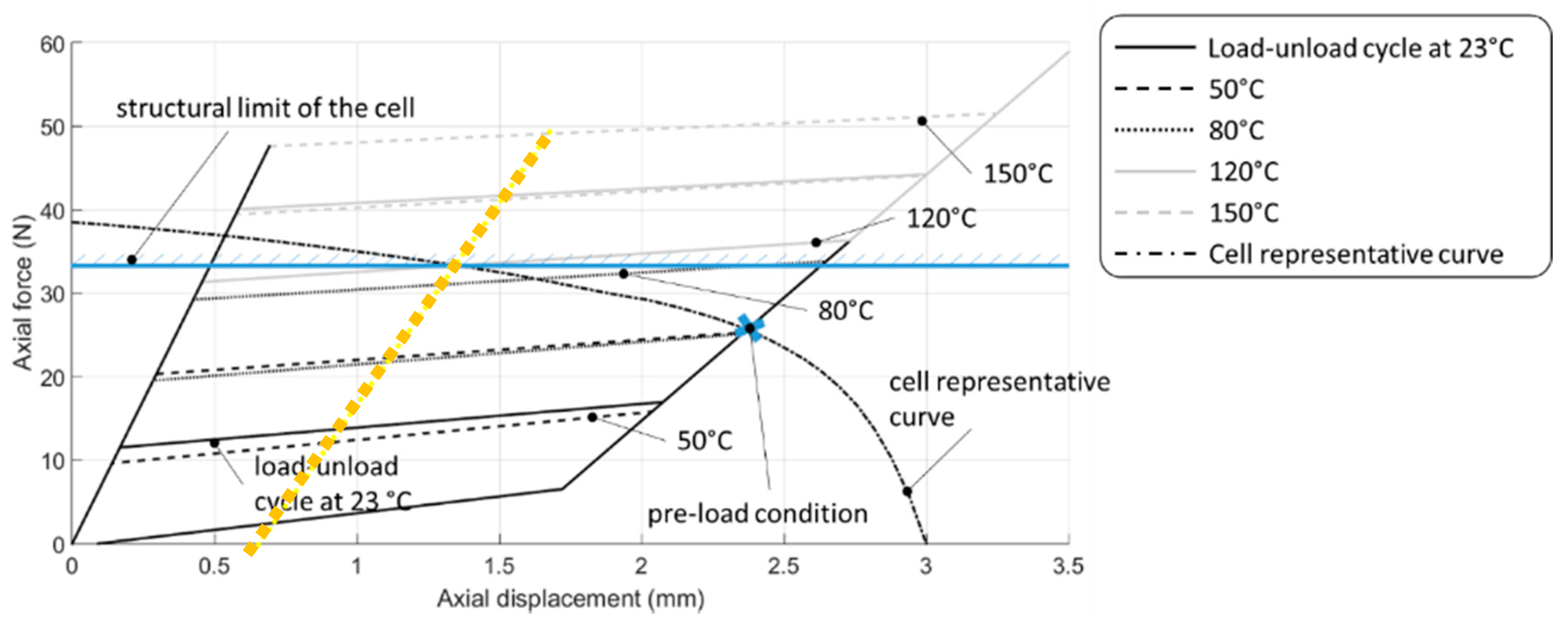
4.2. SMA Wire Modelling and Cell System Integration

Having frozen the cell configuration, SMA element design and integration issues were faced. Shape memory alloys’ properties and wire cross section should have been defined to match general system requirements, with the specific target of maximizing the system expansion/contraction cycle. In this case, the project strategy was based on the implementation of an analytical model able to reproduce the SMA stress-strain-temperature characteristic curve (material constitutive equations), as shown in Figure 3g. In that graph, the elastic curve is the one reported in Figure 8, right. For this target, the model described in [38] was adopted.
Many SMA models have been available in the literature for a long time [39,40,41]. When the authors approached for the first time this class of problems, they needed a recognized model accompanied by a considerable amount of accessible experimental data. The referred model [38] answered that need being also largely used for other works [42,43,44]. After that first choice, the authors themselves constructed a series of experimental data, correlated with numerical predictions performed on their own numerical schematizations, consolidating that approach. They did, therefore, continue in that direction. For the sake of clearness, the used equations are reported, describing the forward (austenite → martensite) transformation:
ξ f w d = [ σ S M A H + σ S M A 2 Δ S 33 + f f w d ( T ) ] ϱ Δ s 0 ( M s 0 M f 0 )
where ξ f w d , σ S M A , H, Δ S 33 , Δ s 0 , ϱ , M s 0 and, M f 0 are the martensite concentration, the current stress within the SMA wire, the maximum recoverable strain, the compliant matrix element in the axial direction of the wire, the entropy change between austenite and martensite phases, the SMA density, and the zero-stress martensite transformation start and finish temperatures, respectively. The function f f w d ( T ) is given by:
f f w d ( T ) = ϱ Δ c [ ( T T 0 ) T ln ( T T 0 ) ] + ϱ Δ s 0 ( T M s 0 )
Therein, T and T 0 are the current and reference temperatures in the order, and Δc is the specific heat coefficients variation between austenite and martensite phases. A further equation is considered to complete the shape memory alloy state representation:
ε 33 = 1 E A + ξ f w d ( E M E A ) σ 33 + H ξ f w d + α ( T T 0 )  
Such a last relation expresses the strain as a function of the martensite concentration, ξ f w d , the stress along the wire direction, σ 33 , and the expansion thermal coefficient, α. Martensite and austenite phases Young’s moduli are represented by the coefficients, E M and E A , respectively. Those and the converse transformation (martensite → austenite) equations were used to track SMA stress-strain curves during loading and unloading paths at different temperatures. This model allowed evaluation of the relative importance of the concurrent parameters in the assigned problem. The characteristic features of the selected SMA material are reported in Table 2. Wire geometry was simply represented through its cross-section area, since only tensile stress is expected.
After the subsystems set-up, the diagram in Figure 3 could be redrawn by considering the actual values. Figure 10 represents the working schematic of the integrated cell architecture. In that graph, the curve representing the elastic behaviour of the structural element (dashed line) refers to an x axis that is reversed with respect to the SMA reference (usual orientation). In fact, negative structural strains (contraction) correspond to a smart wire extension and vice versa. For the sake of clearness, only five full SMA cycles are shown: Grey tones distinguish room (darker) and higher temperatures (lighter and lighter). The intersections between the cell characteristic curve and the bottom segments of the transformation paths (martensite → austenite switch) establish the system equilibrium point at growing temperature values. At 140 °C, the full transformation of the considered alloy was achieved, and the function of the arising stress (as the smart wire contracts, the structure provides growing mechanical resistance as a nonlinear function of the occurring displacement, Figure 8, right). During the tests, heating was handled through adequate thermal shield insulations. Axial translation is reported in Figure 11.
To achieve the required gap recovery in the current application, the 50 mm long SMA wire reached about a 1 mm shrinkage, as shown in Figure 11, corresponding to about 2% strain. According to many authors (e.g., Funakubo [45], SAES Getter [46], and many others), 2% strain can be associated to about 100,000 cycles. In turn, they should match barely 50,000 h travelling (having considered a mean half-an-hour drive per trip at cruise speed, conservatively). At a prudential mean speed of 40 km/h, that value corresponds to 200,000 km. This would mean a substitution every 100–200 thousand km, acceptable for any kind of electromechanical device installed on-board. Of course, these evaluations shall require a more careful study and consideration of many other parameters. Anyway, provided numbers can give an idea of the actual feasibility of the proposed concept. Indeed, thermal aspects should be considered as well. While thermal and mechanical fatigue cannot be dealt with separately, so that the considerations abovementioned hold for the thermomechanical aspect of the SMA, some words shall be spent for the rubber shield. In that case, it is sufficient to refer to the usual material mounted on commercial cars. Because their operational temperature shall be comprised in the range between −50 °C and 80 °C (a car shall be driven at Yakutsk as well as in Las Vegas), the proposed SMA device was designed to be coherent with that temperature range (the device should not have been activated in normal operation conditions, so that activation temperature was set higher than 80 °C). Consequently, the host insulation material should have been selected to have a transformation temperature (glass transition) higher than about 140 °C (50 °C margin, again conservatively). Finally, due to the structural limit of the cell, as shown in Figure 9, having assumed a safety factor of around 1.5 with respect to the ultimate strength, the max temperature was kept under 120 °C. This limitation, highlighted in Figure 11, imposes a partial activation of the SMA material. The dotted line represents the elastic characteristic of the smart material at the allowable transformation, defined as above. It is clear that cycling occurs always along the curve, representative of the structural behaviour of the cell, irrespectively of the phase change percentage (stress-driven transformation).

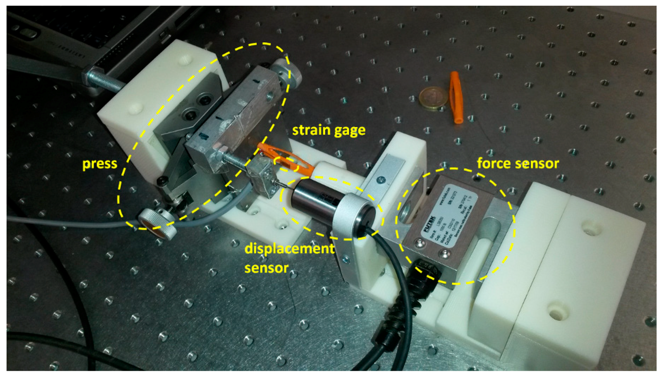
5. Prototyping and Validation

The design phase described above led to the production of executive drawings of a cell prototype for laboratory functionality and mechanical validation. A 3D fused deposition modelling (FDM) printer was used to construct the single cells by extruding a thermoplastic material (ABS). The prototype was used to verify the actual structural properties and validate the proposed theoretical and numerical models. A picture of the realised cell is presented in Figure 12. One out of the three arms was integrated with a strain gage placed at the middle span to monitor deformations at the most critical zone, according to numerical predictions, as shown in Figure 9. No additional strain gage was used for temperature correction, since such tests were performed without SMA and the correlated thermal load; compensations were implemented through the corrective coefficients defined by the manufacturer for the adopted strain gage (EP-08-125BT, Micro-Measurements, Vishay Precision Group Inc, Malvern, PA, USA), characterized by an annealed constantan foil with tough high-elongation polyimide backing and strain range up to about 20% at temperatures between −75 °C to +205 °C.
A dedicated test campaign was then carried out, aimed at acquiring most significant parameters of the integrated system. A specific set-up hosting the cell was prepared: It is outlined in Figure 13 and shown in Figure 14. It was made of the following main components:
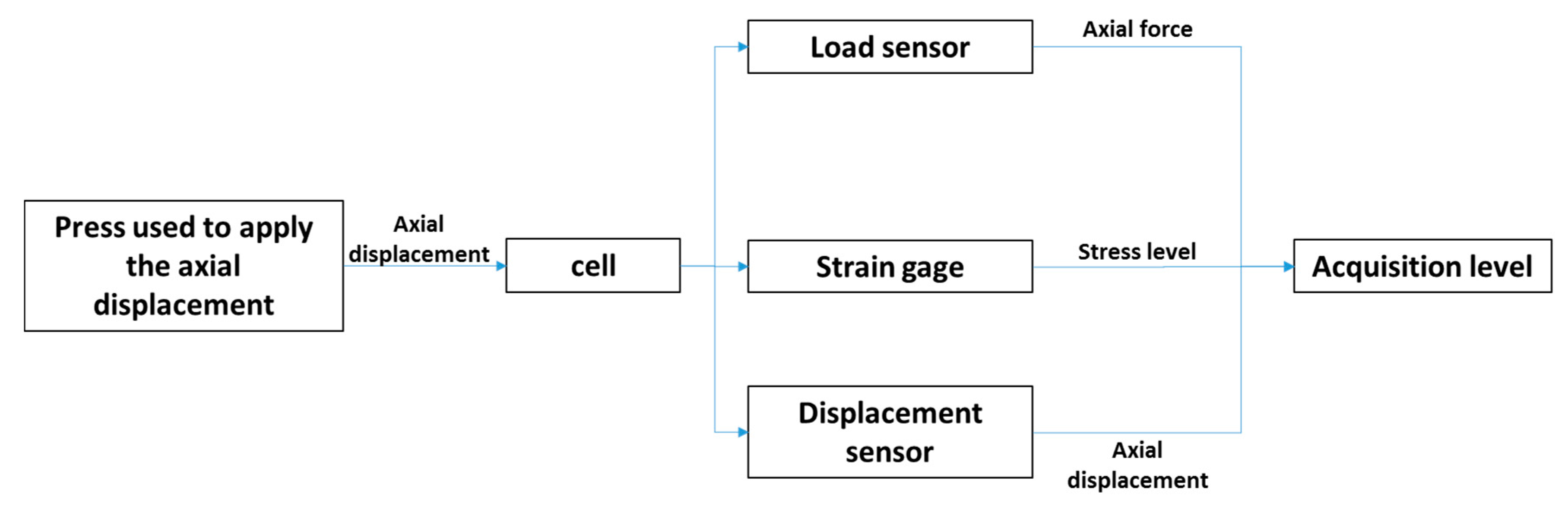
  • Cronos PL8 acquisition system, handling strain gages, linear variable differential transformer (LVDT) and load sensors;
  • a mechanical press to apply axial loads to the cell system;
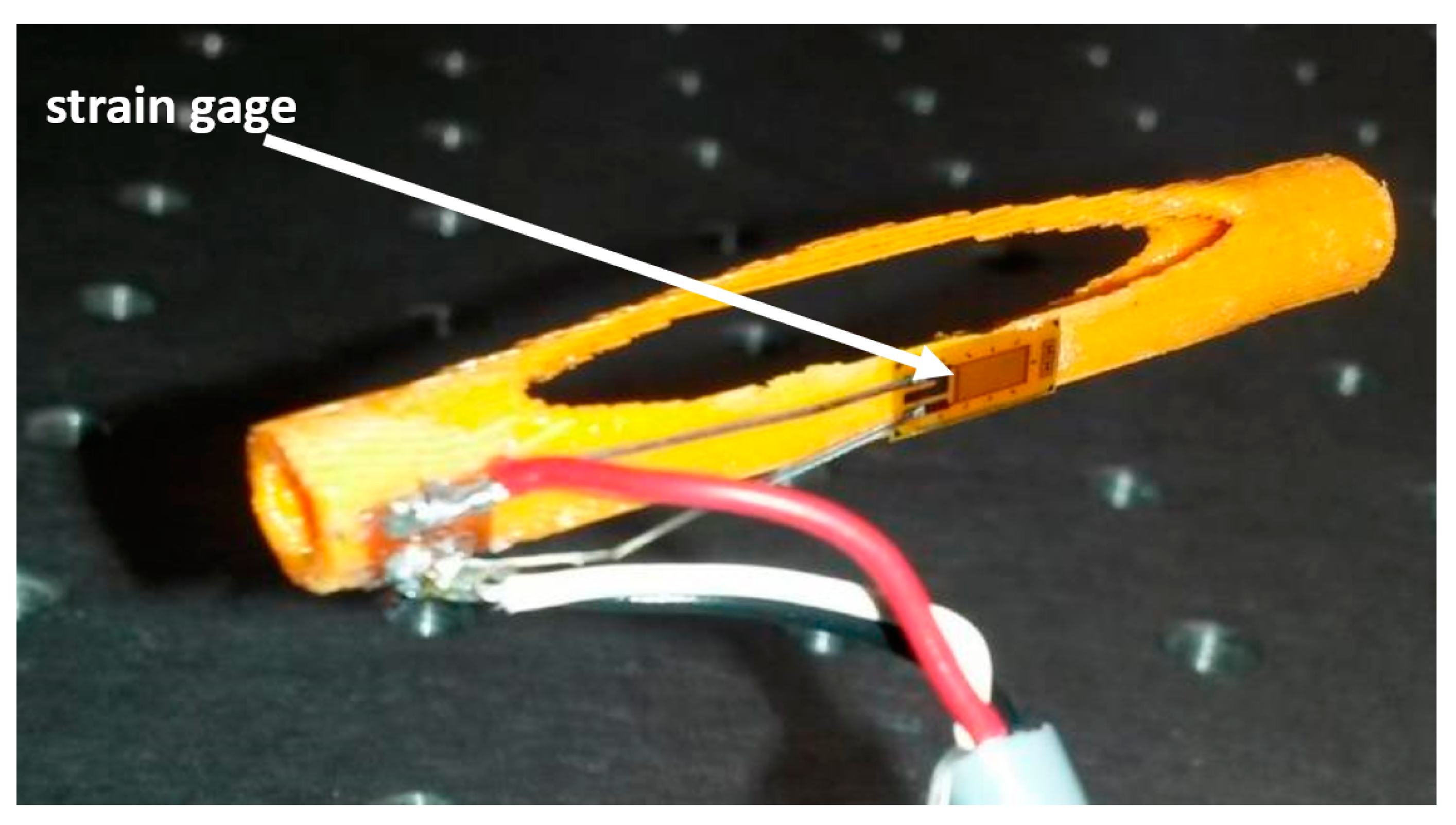
  • a single Vishay Micro-Measurements EP-08-125BT strain gage;
  • an LVDT sensor, for measuring cell axial displacements (compression); and
  • a load cell, to record actual longitudinal load, arisen by the press action.
An experimental tests outcomes summary is reported in Figure 15. A good agreement with the numerical predictions was found, concerning the functional dependence between the applied axial load and strain, measured at the middle of the instrumented arm.
A second prototype was then manufactured, made of three serial cells, each rotated 60° with respect to each other, for a better distribution of the actions on the seal. Such cells were not isolated elements, but built as a whole to achieve augmented compactness levels. The length of a 3-cell device, like the one herein presented, corresponded to the size of the door’s upper corner zone, a critical region for noise transmission as stated in the preliminary sections of this article, Figure 2. A digital mock-up (DMU) shows some details of the proposed system, Figure 16, top. A single SMA wire, clamped at the extremities by hexagonal caps, activated the cluster. A screw system ensured an established and adjustable pre-load, Figure 16, bottom right. Details of this tensioner are seen on the bottom left of the same picture: In the real construction, the SMA wire passed through a threaded hole. An external cylinder (spacer) contained the wire-core assy. A tightening nut was screwed around the core to compress the cell and generate the needed stress within the SMA wire. To reach elastic equilibrium at room temperature, with the SMA wire driven completely into a full de-twinned martensite condition, the pre-load should be at least 22.5 N (“x” marker in Figure 10). That pre-load corresponded to a 0.5 mm axial displacement, Figure 8, left. Teflon cylinders addressing cell thermal protection are shown in Figure 16, bottom right.
A prototype picture is reported in Figure 17. A K-type thermocouple was mounted on the wire surface to monitor temperature values very close to the Teflon cylinders to mitigate the SMA wire heating effects. A stabilized current generator (DELTA Elektronica ES 030-10, 6.1 W max power − 3.2 V × 1.9 A, Delta Elektronika, Zierikzee, Netherlands) was connected to the SMA wire. Power consumption was higher than specified (5 W per door), but it can be widely reduced by using adequate PID control logics that are able to shape the supply ramp during activation and maintain a constant temperature during cruise. Moreover, as shown by Malka and Shilo in [47] and by Motzki et al. in [48], the adoption of suitable voltage and type of signals may further reduce the power absorption. A photo of the experimental setup is shown in Figure 18. A control system drove the generator on and off, assuring a 10% duty cycle with a 60 s excitation period (i.e., 6 s on and 54 s off). Before undergoing the tests, SMA wires were trained in an ad-hoc facility to assess their recovery performance to assure in turn adequate levels of repeatability.
In Figure 19, the achieved cell expansion was compared with its basic state. About a 2.0 mm projected lateral displacement was appraised. Current power consumption in principle depends on many parameters, such as the environmental temperature, the thermal insulation type, the seal material, the air cavity, and so on. Therefore, results should be evaluated by considering these dependences, also in view of a further optimization. A 6.1 W power was achieved at the 23 °C environmental temperature in natural convection without any seal coverage: In that sense, the value is conservative with respect to actual uses. At the lowest operational temperature (−50 °C), the needed additional power is roughly proportional to the temperature increase. Considering a power over temperature ratio of 0.062 W/°C, as measured during the reported experimental campaign (6.1 W/ΔT, ΔT = 97 °C, equal to 120–23 °C, max operational temperature minus environmental temperature), an additional power of about 4.5 W would be necessary. Again, those power estimates may be strongly mitigated by suitable thermal insulations and dedicated control logics.

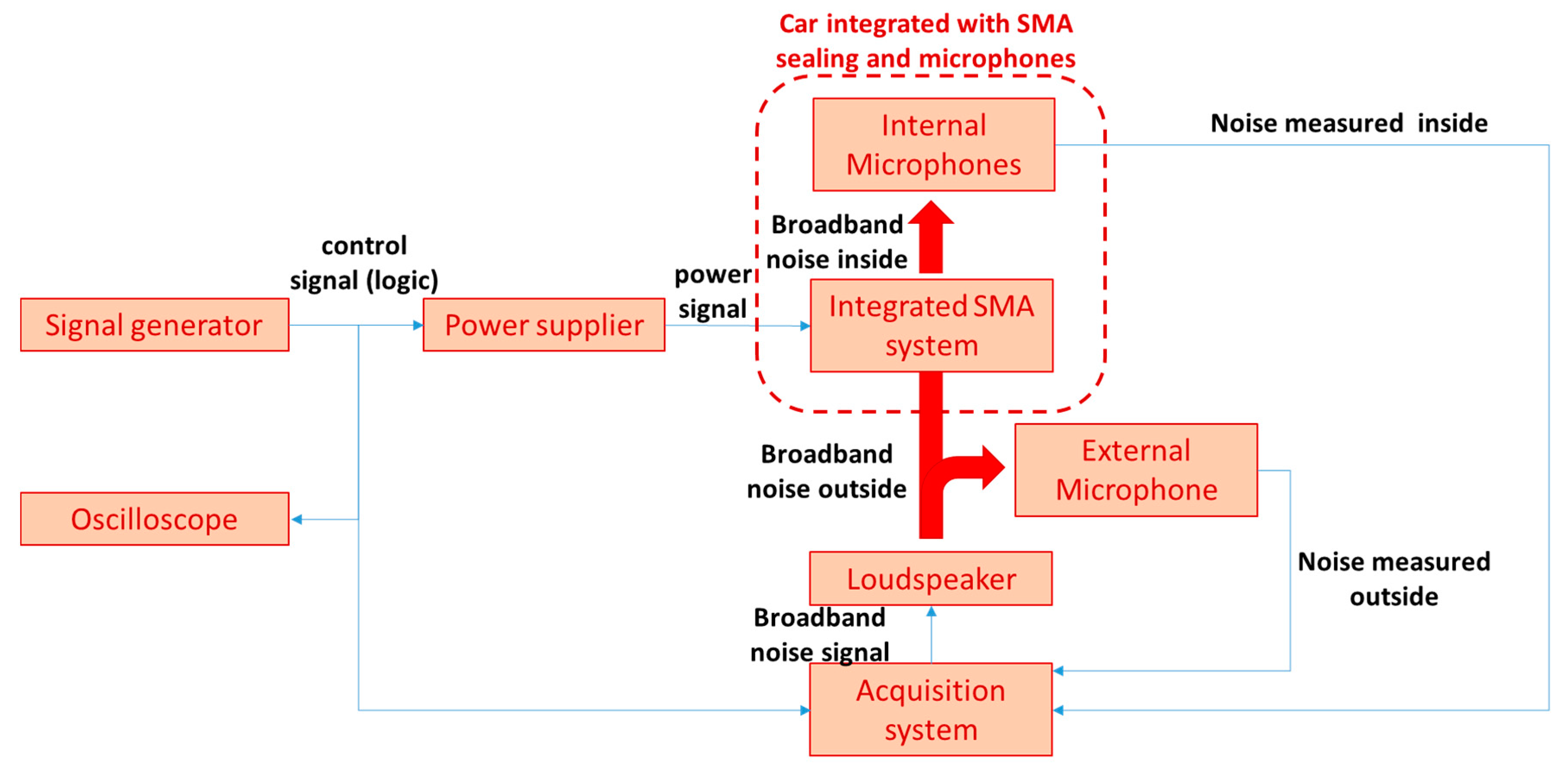
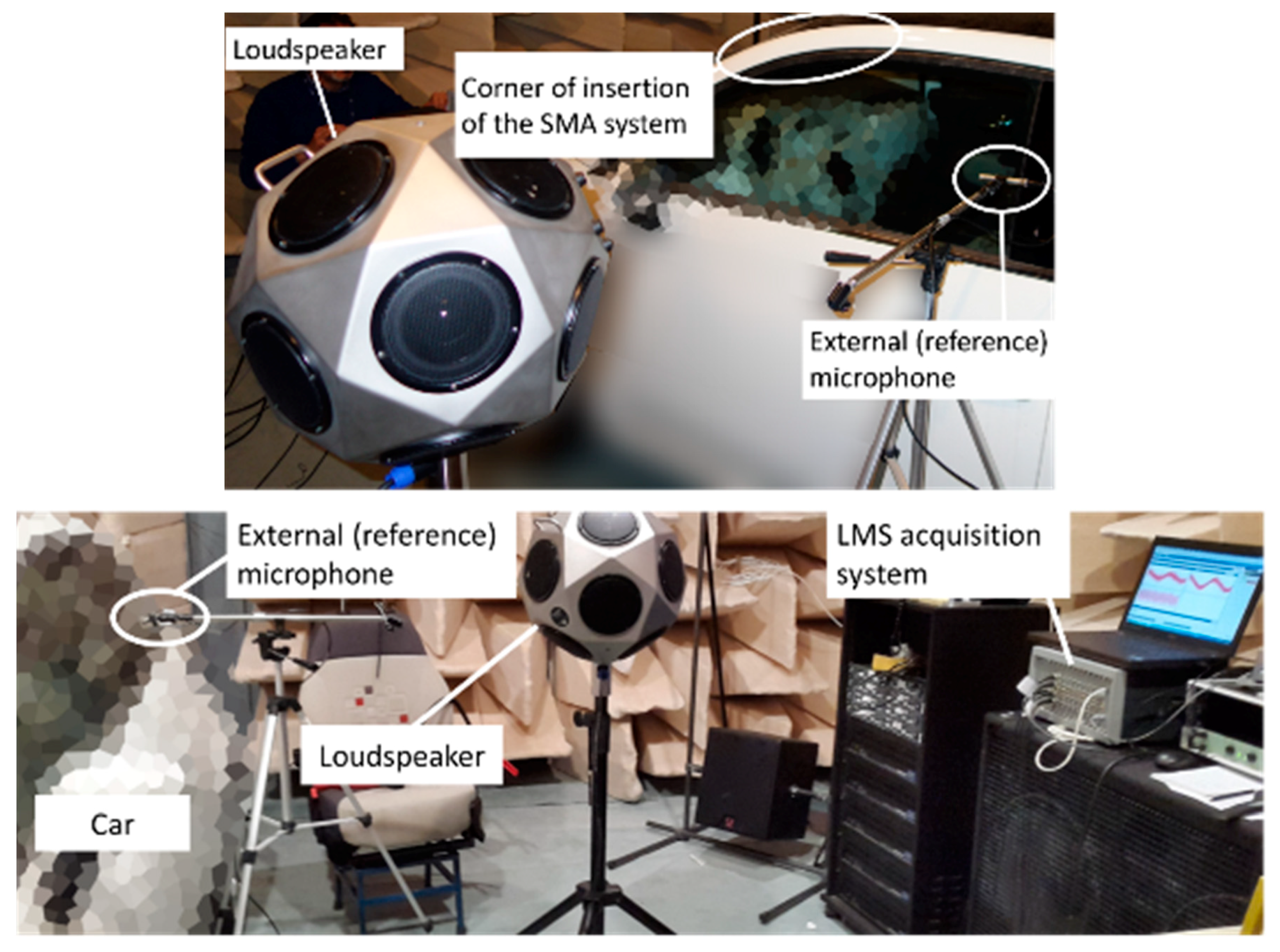
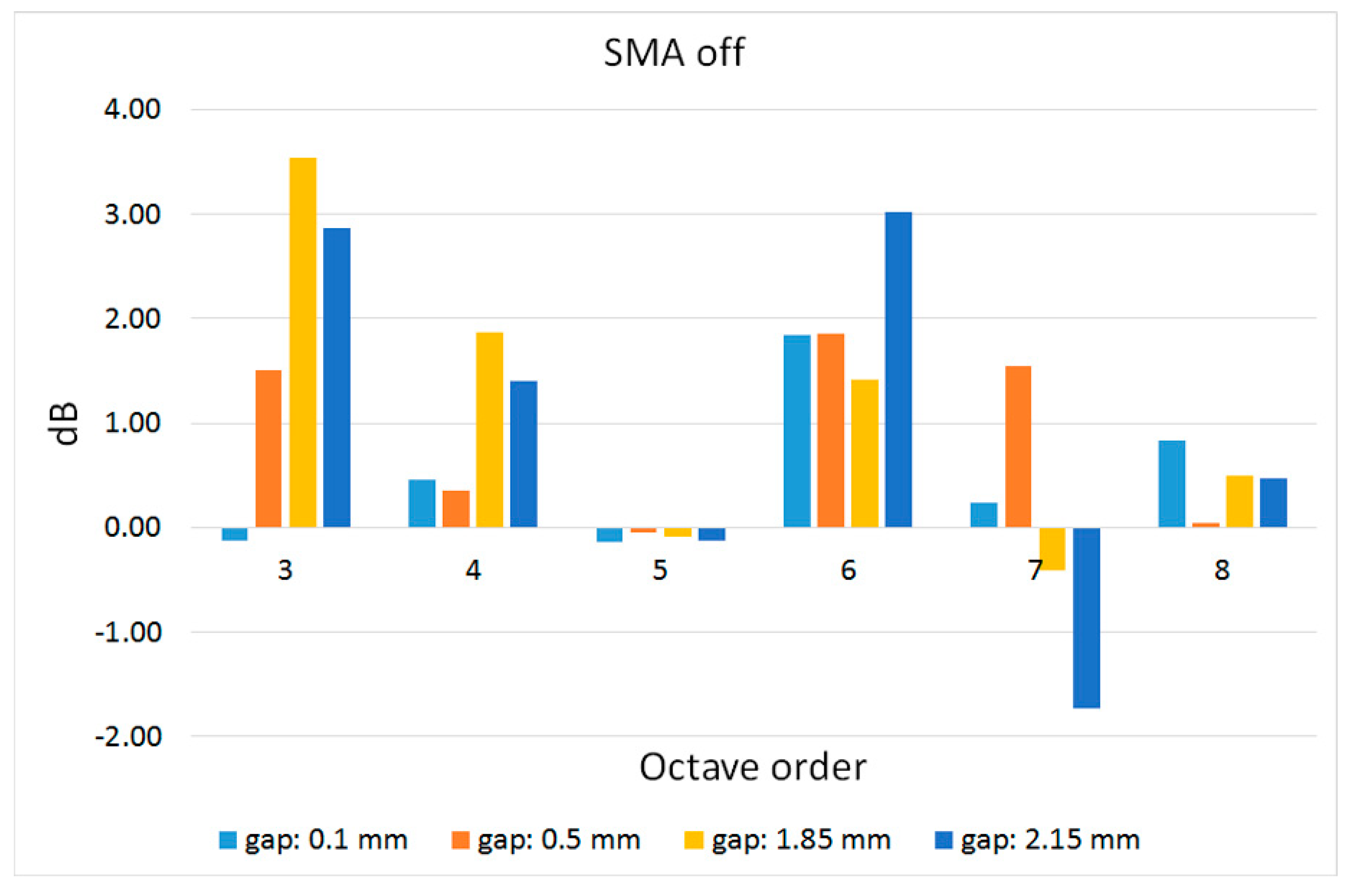
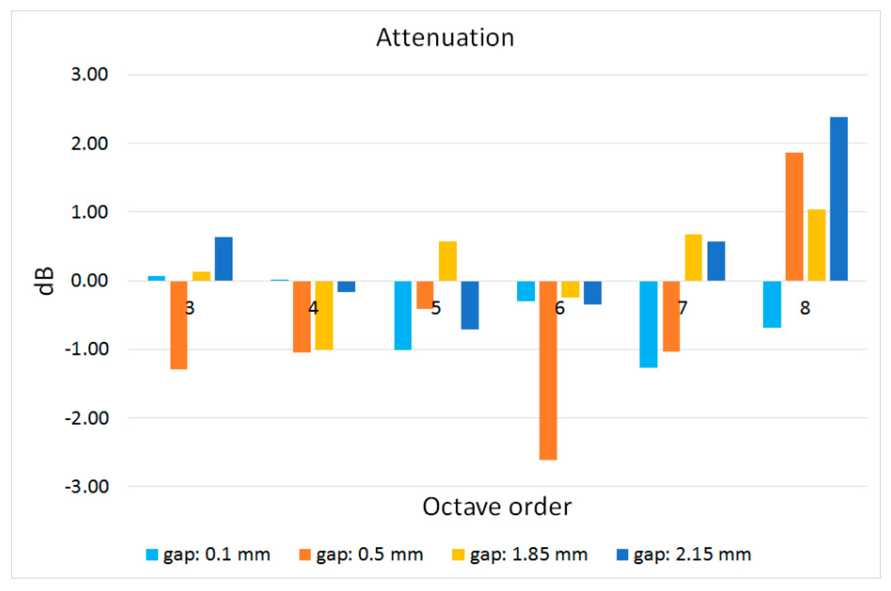
6. Installation and Acoustic Tests

Having proved the mechanical functionality of the system, its integration in an actual car driver’s door was faced. To this purpose, two small holes were drilled in the hollowed seal (Figure 20, before and after the corner of insertion region), close to the area where the acoustic transmission is usually higher, Figure 2, left. Holes permitted power cords to be connected to the internal cell cluster that was then moved to the targeted region. The test car was moved into the semi-anechoic room of CIRA (5.5 × 5.3 × 5.0 m ≈ 145 m3 − 90 Hz cut-off frequency) [49]. The effect produced by the static aerodynamic action on the door was simulated through the screw system shown in Figure 21, mounted on the door frame and modulating the separation (gap) between the door and the main body. To characterize the SMA-based system performance in terms of sound insulation improvement, a dedicated setup was assessed, Figure 22. A signal generator drove the current-stabilized power supply (DELTA Elektronica ES 030-10) for the shape memory alloy wire activation. The driver’s seat head restraint was equipped with two mics (PCB type 377B02, PCB Piezotronics, Depew, NY, USA) to measure the sound field close to the ears. A high-power omnidirectional loudspeaker (Bruel & Kjaer type 4292-L, Brüel & Kjær, Nærum, Denmark) worked as an external noise source, placed about 1 m away from the driver’s door. A reference microphone was mounted close to the driver’s window to tune the disturbance and achieve the required SPL. An SCADAS III LMS acquisition system was used to command sound generators and acquire the mics’ signal. An overview of the entire mock-up in the semi-anechoic room is shown in Figure 23.
The tests were executed for 4 gap sizes, ranging from 0.10 mm to 2.15 mm. This interval, going further than the max expected value for typical aerodynamic-derived pressure action (0.30 mm), was selected to prove system functionality in operative and off-design conditions, for instance, due to undesired seal damage. A linear sine sweep signal (chirp, 50 Hz–8000 Hz) drove the external acoustic source and excited the vibroacoustic system. The internal sound pressure level (SPL) was first measured with the SMA device off. The SPL difference between that value and that recorded externally is reported in Figure 24, for the 3rd to the 8th octave band and for different gap values. The transmitted noise was generally higher for the octave bands, N. 3, 4, and 6, irrespective of the opening size. The active system was then turned on and its effects were measured, Figure 25.
The reported values refer to an average process performed over 20 cycles (microphone signals). The smart cell array required a power level of 6W for each 60 s run. After an activation period, the SMA system was switched off for 120 s so that it could move back to the original strain field. Negative and positive values in Figure 25 indicate SPL attenuation or amplification, respectively. A significant abatement results for the minimum gap investigated (0.10 mm), at the 5th, 6th, 7th, and 8th octave band. A similar behaviour can be observed for the 0.50 mm gap: In that case, SPL reduction is even (slightly) higher for the 6th octave band. More modest effects are observed for larger gaps (1.85 mm and 2.15 mm) where attenuations occur for bands lower than the 6th one, only.
For the octaves where the sound pressure level was amplified, it was understood that the SMA device decreased the sound transmission loss of the seal system. In those cases, the adhesion strength was improved and the gap was reduced, but the overall shape of the net opening was modified. This effect may lead to a negative balance between the incremented seal volume and modified transmission path, particularly at higher frequencies related to the smallest wavelength. The lower performance for larger gaps can be explained by considering cell system geometrical and physical limitations in recovering those openings completely and guaranteeing adequate and homogeneous adhesion forces along the region of interest. These points deserve dedicated analysis and further, targeted tests in an extension of the mentioned project currently under consideration of the authors.

7. Conclusions and Further Steps

In the present work, the development of a system for improving car door acoustic insulation performance was presented. Proposed architecture implemented SMA technology and was based on arrays of expanding cells integrated within a seal cavity. Transversal expansion of cell elements was enforced by shape memory alloy wires’ activation, increasing the volume of the soundproofing filler and then recovering doorframe leakages caused by static aerodynamic forces, which is increasingly important as speed increases. Moving from industrial requirements, the system was preliminarily identified and its functionality was qualitatively described by means of a devoted theoretical model, evaluating its effective transversal actions. The analytical representation was coupled with an equivalent 1D SMA-structure coupled model, developed by the authors and integrated with a well-established SMA constitutive law. System advanced design was carried out considering its nonlinear characteristics. A detailed FE model was realized: Static analysis confirmed the structural behavior of the cell and allowed prediction of the stress and strain levels that resulted within the limits of the selected material (ABS plastics, envisaging further implementation of ALM manufacturing process).
An experimental verification and validation task was finally faced. A first test campaign addressed the relation among the main functional parameters of the isolated, non-instrumented, cell structure. Thus, the link between the applied axial force and induced longitudinal and transversal displacements was found. Good agreement with numerical predictions was found. After this first validation, single and arrays of cell elements were integrated with SMA wires, and coupled system functionality was checked for a number of activation-deactivation cycles. Soundproofing performance of the developed architecture was finally verified in representative conditions. It was integrated within a reference car, placed inside the CIRA semi-anechoic room. Tests were again run for several cycles and proved the system capability of increasing the sound insulation features for different gap values, expression of the increasing aerodynamic forces, and realized through a simple screw system. The achieved results allow consideration of the proposed technology as a promising one, and establishing the TRL (technology readiness level) at 4.
Further steps are planned to further enhance that value. Among others, fatigue and aging behavior should be investigated, particularly important because of the prospected continued use and temperature cycles. Such aspects have impacts on several design steps, ranging from materials selection to the architectural optimization process. Improvements related to energy absorption reduction, including the possible use of bi-stable SMA architectures [50,51,52], are also envisaged to make the system more appealing for actual commercialization. In fact, because of the continuous activation during high-speed driving conditions, energy consumption could be relevant along the vehicle lifetime.

Author Contributions

Conceptualization, A.C., S.A.; methodology, S.A.; software, S.A.; validation, V.Q., S.A., M.C.; formal analysis, S.A., A.C.; investigation, S.A., M.C.; resources, A.B.; data curation, S.A., V.Q.; writing—original draft preparation, S.A.; writing—review and editing, A.C., S.A.; visualization, S.A.; supervision, M.B.; project administration, V.Q.; funding acquisition, M.B., A.C.

Funding

The activities are part of and received funding by the National Project LowNoise (“Nuove tecnologie e materiali per l’abbattimento del rumore degli autoveicoli (in Italian)”, PON_01_01878, starting date: 01/06/2012, duration: 36 months).

Conflicts of Interest

The authors declare no conflict of interest.

References

  1. Hooftman, N.; Messagie, M.; Van Mierlo, J.; Coosemans, T. A review of the European passenger car regulations—Real driving emissions vs local air quality. Renew. Sustain. Energy Rev. 2018, 86, 1–21. [Google Scholar] [CrossRef]
  2. Five Trends Transforming the Automotive Industry. Available online: www.pwc.com/auto (accessed on 26 October 2018).
  3. Yadav, P.; Shinde, A.; Gangurde, Y.; Patil, P. Review on Weight Reduction in Automobile. Int. J. Adv. Technol. Eng. Sci. 2016, 4, 478–483. [Google Scholar]
  4. Simpkin, R.; D’Ambrosio, C.; Simonsson, J.; Abele, M.; Ferrè, A.; Rollenitz, L.; Estrada Vasquez, R.; Boldea, I.; Scridon, S. Energy Efficient Vehicles for Road Transport. Procedia Soc. Behav. Sci. 2018, 48, 3613–3621. [Google Scholar] [CrossRef]
  5. Inomata, S.; Yamada, H.; Tanimoto, H. Investigation on VOC Emissions from Automobile Sources by Means of Online Mass Spectrometry. Curr. Pollut. Rep. 2016, 2, 188–199. [Google Scholar] [CrossRef] [Green Version]
  6. Patil, A.V.; Kumar, B.; Barjibhe, R.B. An Extensive Review on the Use of Acoustic Emission Technique for Continuous Monitoring. Int. Res. J. Eng. Technol. 2016, 3, 137–140. [Google Scholar]
  7. Integrated Solutions for Noise and Vibration Control in Vehicles. Available online: https://cordis.europa.eu/project/rcn/92595_en.html (accessed on 26 October 2018).
  8. Intelligent Materials for Active Noise Reduction. Available online: https://cordis.europa.eu/result/rcn/47813_en.html (accessed on 26 October 2018).
  9. Ecochamps. Available online: http://www.ecochamps.eu/project (accessed on 26 October 2018).
  10. Panda, K.C. Dealing with Noise and Vibration in Automotive Industry. Procedia Eng. 2016, 144, 1167–1174. [Google Scholar] [CrossRef]
  11. Genuit, K.; Bray, W.R. A Virtual Car: Prediction of Sound and Vibration in an Interactive Simulation Environment. J. Passeng. Cars Mech. Syst. J. 2001, 110, 1748–1754. [Google Scholar]
  12. Schulte-Werning, B.; Asmussen, B.; Behr, W.; Degen, K.; Garburg, R. Advancements in Noise and Vibration Abatement to Support the Noise Reduction Strategy of Deutsche Bahn. In Noise and Vibration Mitigation for Rail Transportation Systems; Springer: Berlin, Germany, 2012. [Google Scholar] [CrossRef]
  13. Razak, N.F.D.; Sani, M.S.M.; Azmi, W.H.; Zhang, B. Noise and vibration analysis for automotive radiator cooling fan. In Proceedings of the 4th International Conference on Mechanical Engineering Research (ICMER2017), Pahang, Malaysia, 1–2 August 2017; 2017; Volume 257, p. 012083. [Google Scholar] [CrossRef]
  14. Duffy, K.P.; Padula, S.P.; Scheiman, D.A. Damping of high-temperature shape memory alloys. Proc. SPIE Int. Soc. Opt. Eng. 2008. [Google Scholar] [CrossRef]
  15. Davino, D.; Giustiniani, A.; Visone, C.; Adly, A. Experimental analysis of vibrations damping due to magnetostrictive based energy harvesting. J. Appl. Phys. 2011, 109, 07E509. [Google Scholar] [CrossRef]
  16. Bein, T.; Elliot, S.; Ferralli, L.; Casella, M.; Meschke, J.; Saemann, E.U.; Nielsen, F.K.; Kropp, W. Integrated solutions for Noise and Vibration control in vehicles. Proc. Soc. Behav. Sci. 2012, 48, 919–931. [Google Scholar] [CrossRef]
  17. Liao, Y.; Sodano, H.A. Piezoelectric Damping of Resistively Shunted Beams and Optimal Parameters for Maximum Damping. J. Vib. Acoust. 2010, 132, 041014. [Google Scholar] [CrossRef]
  18. Ciminello, M.; Ameduri, S.; Concilio, A. FE Modeling of an Innovative Vibration Control Shunt Technique. J. Intell. Mater. Syst. Struct. 2007, 19, 875–887. [Google Scholar] [CrossRef]
  19. Ameduri, S.; Diodati, G.; Concilio, A. SMA Embedded Panel Optimized Through a Genetic Approach. J. Intell. Mater. Syst. Struct. 2009, 20, 1529–1540. [Google Scholar] [CrossRef]
  20. Bettini, P.; Riva, M.; Sala, G.; Di Landro, L.; Airoldi, A.; Cucco, J. Carbon Fiber Reinforced Smart Laminates with Embedded SMA Actuators—Part I: Embedding Techniques and Interface Analysis. J. Mater. Eng. Perform. 2009, 18, 664–671. [Google Scholar] [CrossRef]
  21. Spaggiari, A.; Dragoni, E. Analytical and numerical modeling of shape memory alloy Negator springs for constant-force, long-stroke actuators. J. Intell. Mater. Syst. Struct. 2013, 25, 1139–1148. [Google Scholar] [CrossRef]
  22. Reynaerts, D.; Van Brussel, H. Design aspects of shape memory actuators. Mechatronics 1998, 8, 635–656. [Google Scholar] [CrossRef]
  23. Nespoli, A.; Besseghini, S.; Pittaccio, S.; Villa, E.; Viscuso, S. The high potential of shape memory alloys in developing miniature mechanical devices: A review on shape memory alloy mini-actuators. Sens. Actuators A Phys. 2010, 158, 149–160. [Google Scholar] [CrossRef]
  24. Ishii, H.; Ting, K.L. SMA actuated compliant bistable mechanisms. Mechatronics 2004, 14, 421–437. [Google Scholar] [CrossRef]
  25. Zisser, H.C. The OmniPod Insulin Management System: The latest innovation in insulin pump therapy. Diabetes Ther. 2010, 1, 10–24. [Google Scholar] [CrossRef]
  26. Kuszneruk, P. SMA Valve Assembly for Controlling Pressurized Air Supply to Air Cells in a Vehicle Seat. European Patent Application, NO. EP3281821A1, 8 August 2016. [Google Scholar]
  27. Williams, E.A.; Shaw, G.; Elahinia, M. An Automotive SMA Mirror Actuator: Modeling, Design, and Experimental Evaluation. Mechatronics 2010, 20, 527–534. [Google Scholar] [CrossRef]
  28. Kazi, A.; Honold, M.; Rimkus, W.; Lokner, T.; Baeuml, M.; Koepfer, M. SMA Actuator for Optical Image Stabilization, Paper C5.1, Actuator 2018, Bremen (D). In Proceedings of the ACTUATOR 2018, 16th International Conference on New Actuators, Bremen, Germany, 25–27 June 2018; pp. 375–378. [Google Scholar]
  29. Frangibolt. Available online: https://tiniaerospace.com/products/space-frangibolt/ (accessed on 20 November 2018).
  30. Butera, F. SmartFlex Springs and SmartFlex Wires, by SAES Getter. Available online: https://docplayer.net/23849945-Smas-for-industrial-applications-from-first-nitinol-to-a-big-success.html (accessed on 20 November 2018).
  31. Ameduri, S.; Brindisi, A.; Ciminello, M.; Concilio, A.; Quaranta, V.; Brandizzi, M. An SMA Sealing System for Enhanced Door Soundproof Performance: Design, Prototyping and Testing. In Proceedings of the ACTUATOR 2018, 16th International Conference on New Actuators, Bremen, Germany, 25–27 June 2018; pp. 379–383. [Google Scholar]
  32. Jani, J.M.; Leary, M.; Subic, A. Shape Memory Alloys in Automotive Applications. Appl. Mech. Mater. 2014, 663, 248–253. [Google Scholar] [CrossRef]
  33. Ameduri, S.; Concilio, A.; Pecora, R.; Karagiannis, D. A Single Slotted Morphing Flap Based on SMA Technology. Smart Struct. Syst. 2016, 17, 819–835. [Google Scholar] [CrossRef]
  34. Lecce, L.; Concilio, A. (Eds.) Shape Memory Alloys Engineering for Aeronautical, Medical and Civil Applications; Butterworth-Heinemann: Oxford, UK, 2014; 448p, ISBN 978-0-08-099920-3. [Google Scholar] [CrossRef]
  35. Concilio, A.; Ameduri, S. Influence of structural architecture on linear shape memory alloy actuator performance and morphing system layout optimization. J. Intell. Mater. Syst. Struct. 2013, 25, 2037–2051. [Google Scholar] [CrossRef]
  36. Jani, J.M. Design Optimisation of Shape Memory Alloy Linear Actuator Applications. Ph.D. Thesis, RMIT University, Melbourne, Australia, 2016. [Google Scholar]
  37. Timoshenko, S.P.; Gere, J.M. Theory of Elastic Stability, 2nd ed.; International Student Edition; Mc Graw-Hill International Book Company: New York, NY, USA, 1985; pp. 76–82. ISBN 0-07-Y85821-7. [Google Scholar]
  38. Mirzaeifar, R.; DesRoches, R.; Yavari, A. A combined analytical, numerical, and experimental study of shape-memory-alloy helical springs. Int. J. Solids Struct. 2011, 48, 611–624. [Google Scholar] [CrossRef]
  39. Liang, C.; Rogers, C.A. A multi-dimensional constitutive model for shape-memory alloys. J. Eng. Math. 1992, 26, 429–443. [Google Scholar] [CrossRef]
  40. Huang, M.S.; Brinson, L.C. A multivariant model for single crystal shape memory alloy behavior. J. Mech. Phys. Solids 1998, 16, 1379–1409. [Google Scholar] [CrossRef]
  41. Patoor, E.; Lagoudas, D.C.; Entchev, P.; Brinson, L.C.; Gao, X. Shape-memory alloys, part I: General properties and modeling of single crystal. Mech. Mater. 2006, 38, 391–429. [Google Scholar] [CrossRef]
  42. Mehrabi, R.; Masood, T.A.; Elahinia, M.; Kadkhodaeid, M. Anisotropic behavior of superelastic NiTi shape memory alloys; an experimental investigation and constitutive modeling. Mech. Mater. 2014, 77, 110–124. [Google Scholar] [CrossRef]
  43. Andani, M.T.; Elahinia, M. A rate dependent tension–torsion constitutive model for superelastic nitinol under non-proportional loading; a departure from von Mises equivalency. Smart Mater. Struct. 2014, 23, 015012. [Google Scholar] [CrossRef]
  44. Ameduri, S.; Concilio, A. An SMA Torsion Actuator for Static Blade Twist. In Proceedings of the ICAST2018: 29th International Conference on Adaptive Structures and Technologies, Seoul, Korea, 30 September–4 October 2018. [Google Scholar]
  45. Funakubo, M. Shape Memory Alloys; Taylor & Francis: Abingdon, UK, 1987; 276p, ISBN1 2881241360. ISBN2 9782881241369. [Google Scholar]
  46. Introduction to Nitinol; Memry Corporation: Bethel, CT, USA, 28 December 2017.
  47. Malka, Y.; Shilo, D. A fast and powerful release mechanism based on pulse heating of shape memory wires. Smart Mater. Struct. 2017, 26, 095061. [Google Scholar] [CrossRef]
  48. Motzki, P.; Gorges, T.; Kappel, M.; Schmidt, M.; Rizzello, G.; Seelecke, S. High-Speed and High-Efficiency Shape Memory Alloy Actuation. Smart Mater. Struct. 2018, 27, 075047. [Google Scholar] [CrossRef]
  49. Vibro-Acoustic Characterisation Laboratory. Available online: https://www.cira.it/en/research-infrastructures/vibro-acoustic-characterisation-laboratory (accessed on 7 December 2018).
  50. Browne, A.L.; Johnson, N.L.; Mc Knight, G.P.; Keefe, A.C.; Herrera, G.A. Reconfigurable Bi-Stable Device. US Application NO. US 20130081933 A1, 4 April 2013. [Google Scholar]
  51. Motzki, P.; Seelecke, S. Bistable actuator device having a shape memory element. World Intellectual Property Organization Patent NO. WO 2017/194591 AI, 16 November 2017. [Google Scholar]
  52. Morgen, R.; Yee, H.H. Electro-Thermal Bi-Stable Actuator. US Grant US5977858A, 2 November 1999. [Google Scholar]
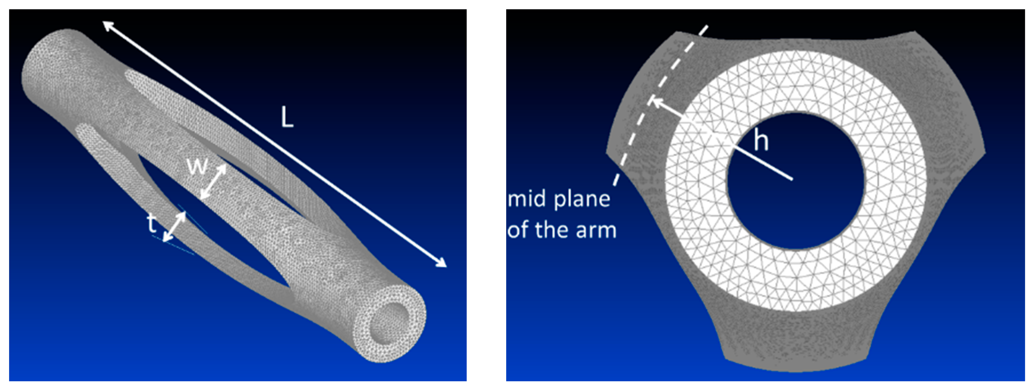
Figure 1. Qualitative representation of the phenomenon. Oriented lines represent external airflow, while bold arrows represent the actions of the internal static pressure field.
Actuators 07 00088 g001
Figure 2. Driver’s door: Generated displacement field (left); sealing lift curve versus clearance (right).
Actuators 07 00088 g002
Figure 3. Integration process of the cell with the SMA wire (ad), installation and activation within the seal (e,f), stress-strain curve comparison for the SMA and the cell vs the different integration phases (g). Cyclic transformation between de-twinned martensite (or stress-driven martensite) and austenite phases.
Actuators 07 00088 g003
Figure 4. Cell ellipsoid geometry (left), three-arm configuration (right).
Actuators 07 00088 g004
Figure 5. Structural schematic for simulating the behavior of a single arm of the cell.
Actuators 07 00088 g005
Figure 6. Transversal displacement (Δy), applied load (P) and load normalized with respect to critical buckling load (P/Pcr) as a function of axial (Δx) and transversal (Δy) displacements, and their ratio (Δy/Δx), respectively. Curves parameterized vs the shape coefficient (h/L) in the range of 1%–2%.
Actuators 07 00088 g006
Figure 7. Finite element model of the cell body: global view and main dimensions (left); mid-span cross-section (right) [30].
Actuators 07 00088 g007
Figure 8. Cell radial displacement (left) and axial force (right) versus axial displacement.
Actuators 07 00088 g008
Figure 9. Von Mises strain map: 2 mm transversal displacement, corresponding to a 1 mm axial contraction.
Actuators 07 00088 g009
Figure 10. Operational points of the expanding cell.
Actuators 07 00088 g010
Figure 11. Axial displacement versus temperature.
Actuators 07 00088 g011
Figure 12. Prototype of a single cell.
Actuators 07 00088 g012
Figure 13. Scheme of the setup used for laboratory validation.
Actuators 07 00088 g013
Figure 14. Experimental setup for laboratory tests [30].
Actuators 07 00088 g014
Figure 15. Axial load vs strain on the arms, numerical vs experimental results [30].
Actuators 07 00088 g015
Figure 16. Digital mockup of a 3-cell cluster, integrated with an SMA wire: global view (top); detail of the terminal (bottom) with a further magnification on the connection segment (bottom, top right).
Actuators 07 00088 g016
Figure 17. Three cells prototype, integrated with the SMA wire [30].
Actuators 07 00088 g017
Figure 18. Setup for estimating the transversal displacement produced by the SMA wire.
Actuators 07 00088 g018
Figure 19. Cell functionality: Fully activated (right), no active (left).
Actuators 07 00088 g019
Figure 20. Integration of the SMA adaptive system within the door seal.
Actuators 07 00088 g020
Figure 21. Screw system for generating a gap between the seal and the door frame; general view (left); detail (right).
Actuators 07 00088 g021
Figure 22. Schematics of the setup for acoustic characterization [30].
Actuators 07 00088 g022
Figure 23. Experimental mock up: lateral (top) and front (bottom) view with some details of the excitation and acquisition systems.
Actuators 07 00088 g023
Figure 24. Sound pressure level without activating the SMA system.
Actuators 07 00088 g024
Figure 25. Sound pressure level abatement due to the activation of the SMA system [30].
Actuators 07 00088 g025
Table 1. Main features of the cell FE model.
Length (mm)Transversal Size (mm)Number of ArmsArms Thickness (Average Value, mm)Arms Width (Average Value, mm)ElementsNodesYoung’s Modulus (GPa)Poisson’s Ratio (-)
50531.52.6175930379472.30.32
Table 2. Features of the SMA active element.
Wire Length (mm)Diameter (mm)Young’s Modulus (GPa)Poisson’s Ratio (-)Transformation Temperatures (°C)Maximum Recoverable Strain (%)
E M E A Mf0Ms0As0Af0
500.2515250.32−24.9−8.55.724.03.0

