A Novel Actuator System Combining Mechanical Vibration and Magnetic Wheels Capable of Rotational Motion Using Shape Memory Alloy Coils


Faculty of Engineering, Tohoku Gakuin University, 985-8537, 1-13-1 Chuo, Tagajo, Japan
*
Author to whom correspondence should be addressed.
Actuators 2019, 8(1), 4; https://doi.org/10.3390/act8010004
Submission received: 6 December 2018
/
Revised: 26 December 2018
/
Accepted: 29 December 2018
/
Published: 4 January 2019
(This article belongs to the Special Issue Actuators Based on Shape Memory Alloys)
Abstract
:In every country, large steel bridges, such as cable-stayed bridges, are actively being constructed, and the number of such bridges has been progressively increasing. These bridges are often inspected using drones, but inspection techniques have not been established because of strong winds and thunder. Therefore, robots capable of working in difficult environments are desired. In the present study, a prototype of a rotary actuator system combining two iron disks and two electromagnetic-vibration-type actuators was fabricated. A new operation principle was developed that drives the system using the reaction force of the vibration-type actuator. Two shape memory alloy coils and two friction pads were integrated into the system to enable it to carry out turning operations, which were successfully demonstrated. The proposed actuator system can thus move in any direction. In addition, with this actuator system, both slide-on-ceiling and wall-climbing motions are possible.
1. Introduction
In every country, large steel bridges, such as cable-stayed bridges, are actively being constructed, and the number of such bridges has been progressively increasing. These large structures are subjected to a surface inspection once every five years. At present, inspections of large bridges with spans of over 200 m are conducted by combining elevated work vehicles and telephoto vision. Furthermore, it is necessary to regularly inspect large iron tanks with outer diameters of over 100 m. These inspections are made possible by building scaffolds for such large tanks. However, there are problems with current inspection methods in that microcracks cannot be reliably detected. Inspections using drones have also been conducted, but inspection techniques have not been established because of strong winds and thunder. Therefore, on the basis of the above considerations, robots capable of working in difficult environments are desired.
Previously proposed adhesion methods for wall surface movement include the following: a permanent magnetic adhesion system [1,2], the adhesive force generated by a suction cup [3] or flexible rubber [4,5,6,7,8], controlling the attractive force of an electromagnet [9], a permanent magnet combined with an iron wheel [10,11,12,13], the negative pressure of a pump [14,15], the wind force produced by a propeller [16], the vibration of the many caps [17,18], a claw gripper [19,20,21], and adhesive materials [22,23]. However, these methods involve complicated mechanisms and require the adhered device to have a relatively large weight. The authors have previously proposed a magnetic actuator capable of moving on a magnetic structure by coupling a magnetic force and mechanical resonance [24,25]. This magnetic actuator has a simple structure and is inexpensive to manufacture. However, this actuator is limited to movement in one direction, and cannot move if there is rust or corrosion on the surface of the target structure.
In the present study, a prototype of a rotary actuator system combining two iron disks and two electromagnetic-vibration-type actuators was fabricated. A new operation principle was developed in which the system is driven by the reaction force of the vibration-type actuator. Two shape memory alloy (SMA) coils and two friction pads were integrated into the actuator system to achieve rotational motion. This actuator system was demonstrated to be capable of turning operations. This magnetic-wheel-type actuator system is able to climb upward at a speed of 24 mm/s while pulling a load mass of 120 g when the attractive force of the rubber magnet is 1.78 N, and can realize both slide-on-ceiling and wall-climbing motions. The actuator system was confirmed to be able to move on a magnetic substance, such as an iron rail, supplied by only a function generator and a power amplifier.
2. Structure of the Vibration-Type Actuator and Actuator System
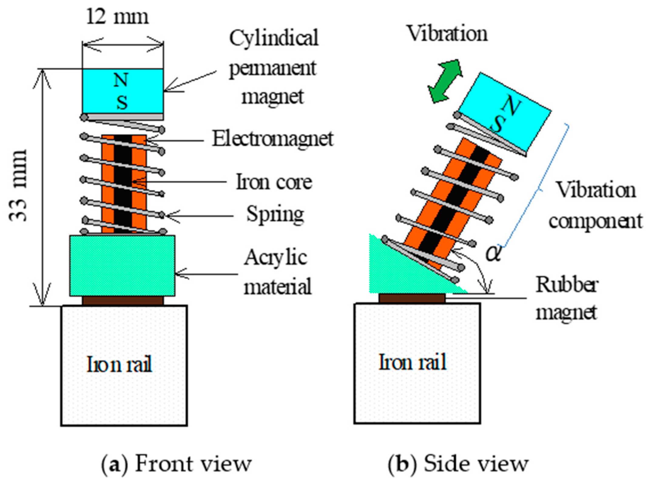
Figure 1 shows a diagram of the developed vibration-type actuator capable of moving on a magnetic substance. The vibration-type actuator consists of a cylindrical permanent magnet, a translational spring, an electromagnet with an iron core, a triangular acrylic frame, and a rubber permanent magnet attached to the bottom of the frame. The cylindrical permanent magnet is composed of NdFeB and is magnetized in the axial direction. It has an outer diameter of 12 mm and a thickness of 5 mm. The surface magnetic flux density measured by a Tesla meter was 322 mT. The translational spring is a stainless steel compression coil with an outer diameter of 11 mm, a free length of 18 mm, and a spring constant k of 2178 N/m. The vibration component consists of the translational spring and the cylindrical permanent magnet, and the electromagnet is inserted into the translational spring. The rubber permanent magnet is magnetized in the thickness direction and has a length of 9 mm, a width of 15 mm, and a thickness of 2.8 mm. The average surface magnetic flux density measured by a Tesla meter was 116 mT. The angle α of the mass-spring model was set to 60° based on the results obtained in a previous study [24]. The actuator has a height of 42 mm, a width of 15 mm, and a total mass of 13.5 g. The attractive force generated by the flexible rubber magnet attached at the support part acts on the actuator when it is placed on a magnetic structure, as shown in Figure 2. The frictional force between the flexible magnet and the magnetic substance alternates periodically during the vibration. Since the horizontal component of the inertial force exceeds the frictional force, the vibration-type actuator is propelled by the difference between the frictional forces in the forward and backward directions acting on the flexible rubber magnet in the support, as shown in a previous study [25]. First, the movement characteristics of this vibration-type actuator were examined.
An iron rail of 50 mm in width, 50 mm in thickness, and 400 mm in length was used as the target magnetic structure. The vibration component of the vibration-type actuator was driven at the resonance frequency using a function signal generator and an amplifier. The resonance frequency was 97 Hz. The coefficient of friction between the iron rail and the flexible magnet measured in the experiment was 0.67. The attractive force F of the flexible magnet measured using a force gauge was 1.78 N. The coefficient of friction and the attractive force F were fixed during the experiment.
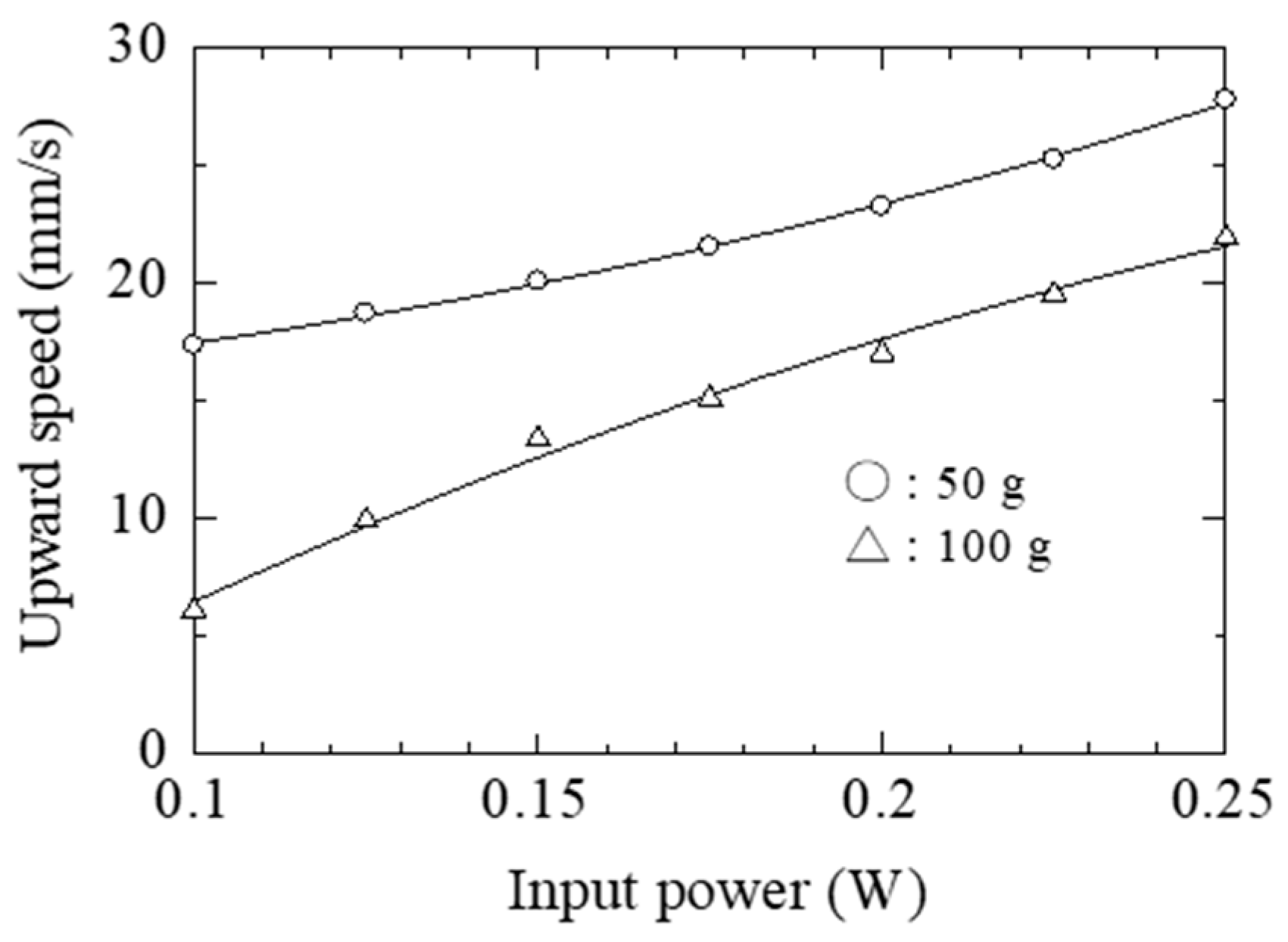
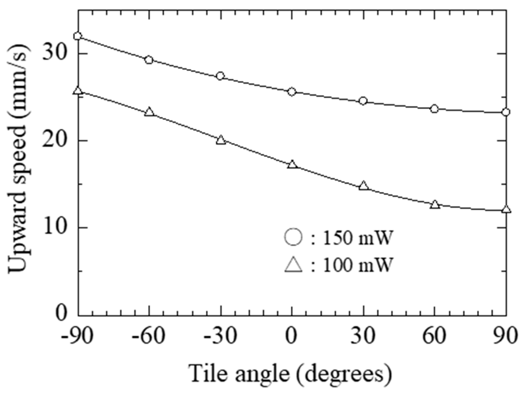
Figure 3 shows the relationship between the power input to the electromagnet and the speed of the vertical upward movement when the mass loaded on the actuator was set to 50 and 100 g. Figure 4 shows the relationship between the tilt angle α of the iron rail and the speed of the actuator at input powers of 100 and 150 mW. From these results, considering the size and weight of the system, this vibration-type actuator shows good movement characteristics. However, the vibration-type actuator is capable of movement in only one direction, and to inspect the state of a target structure, it is necessary to move in all directions. As described above, the vibration-type actuator realizes unidirectional movement by periodically changing the frictional force of the rubber magnet adhered to the support portion. This means that the movement characteristics of the actuator are also dependent on the rust and corrosion conditions of the surface of the target iron structure.
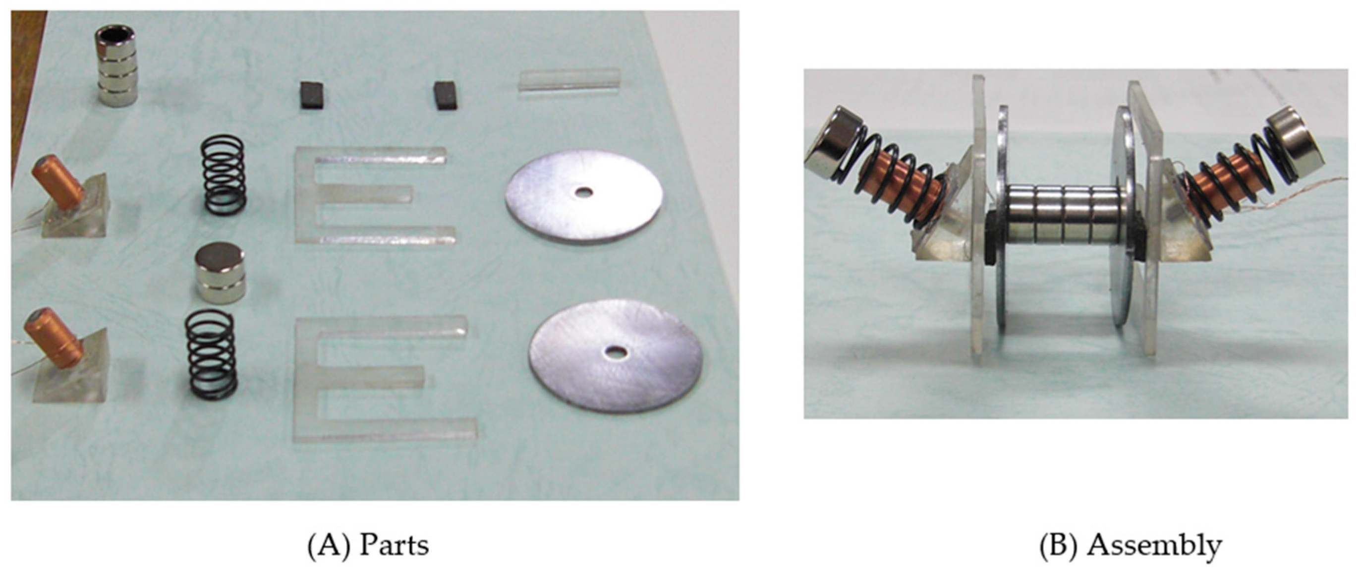
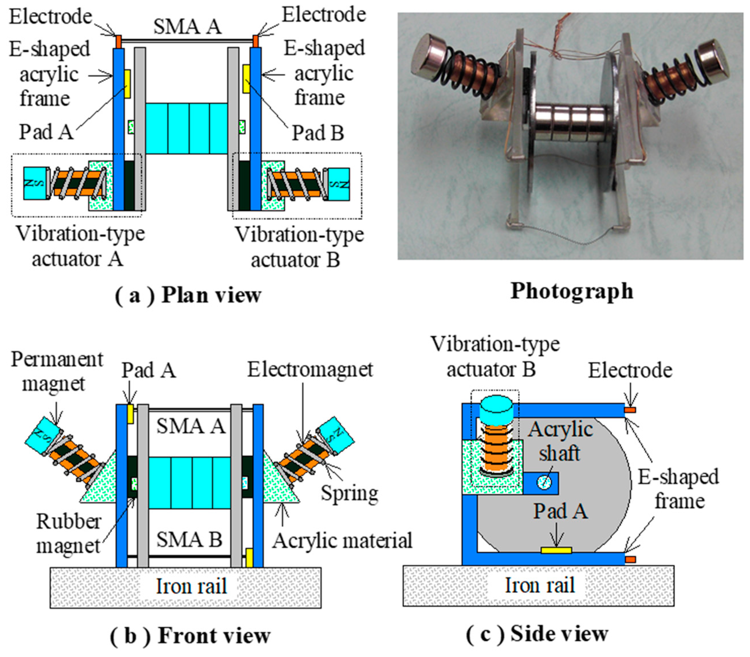
In the present study, a new actuator system capable of movement on a magnetic surface was developed. Figure 5 shows the proposed rotary actuator system, which combines a magnetic wheel, composed of two iron disks and an electromagnet, with the electromagnetic-vibration-type actuator. The actuator system consists of two electromagnetic-vibration-type actuators, labeled A and B; an E-shaped acrylic material; four magnetic rings; an acrylic shaft; and two iron disks. Electromagnetic-vibration-type actuators A and B are held by the E-shaped acrylic frame and rotate the two iron disks using the reaction force of the vibration-type actuator. In this actuator system, magnetic paths are formed by the magnetic wheels, electromagnets, and iron structures. Furthermore, because the frictional force between the iron disk and the rubber magnet of the vibration-type actuator can be kept constant, the frictional force during the rotational movement of the actuator system on the structure does not change. Figure 6 shows a photograph of the magnetic actuator system and parts and assembly.
In the production of a prototype of the magnetic-wheel-type actuator system, two vibration-type actuators with the same driving frequency and moving characteristics were produced. The E-shaped acrylic frame was made from a 1 mm-thick flat plate using a three-dimensional (3D) processing machine. The dimensions of the E-shaped frame in this figure correspond to iron disks of 40 mm in diameter.
3. Principle of Locomotion
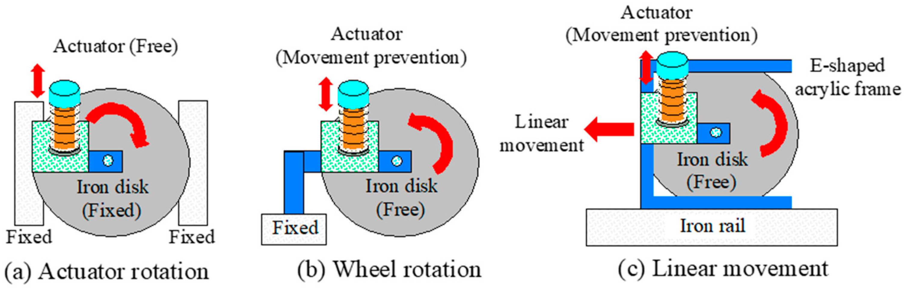
As shown in Figure 7, the vibration-type actuator is vibrated by the attractive force of the rubber magnet. The vibration-type actuator moves as a result of the vertical and horizontal components of the forces generated by the vibration component attached at an angle of 60°. When the vibration-type actuator with a rubber magnet is placed on a fixed iron disk, the vibrating body of the actuator moves in the direction in which the vibration component is tilted.
When a supported state is imposed to prevent the motion of the vibration-type actuator, the iron disk rotates as a result of the reaction force of the actuator as a center on the acrylic shaft. By inserting the vibration-type actuator into the E-shaped acrylic frame in such a way that it is attracted to the iron disk, as shown in Figure 7, it is possible to rotate the disk while preventing the movement of the actuator. In the present actuator system, vibration-type actuators A and B rotate the corresponding iron disks A and B, thereby enabling the system to move linearly over an iron structure.
4. Locomotive Characteristics of Actuator System
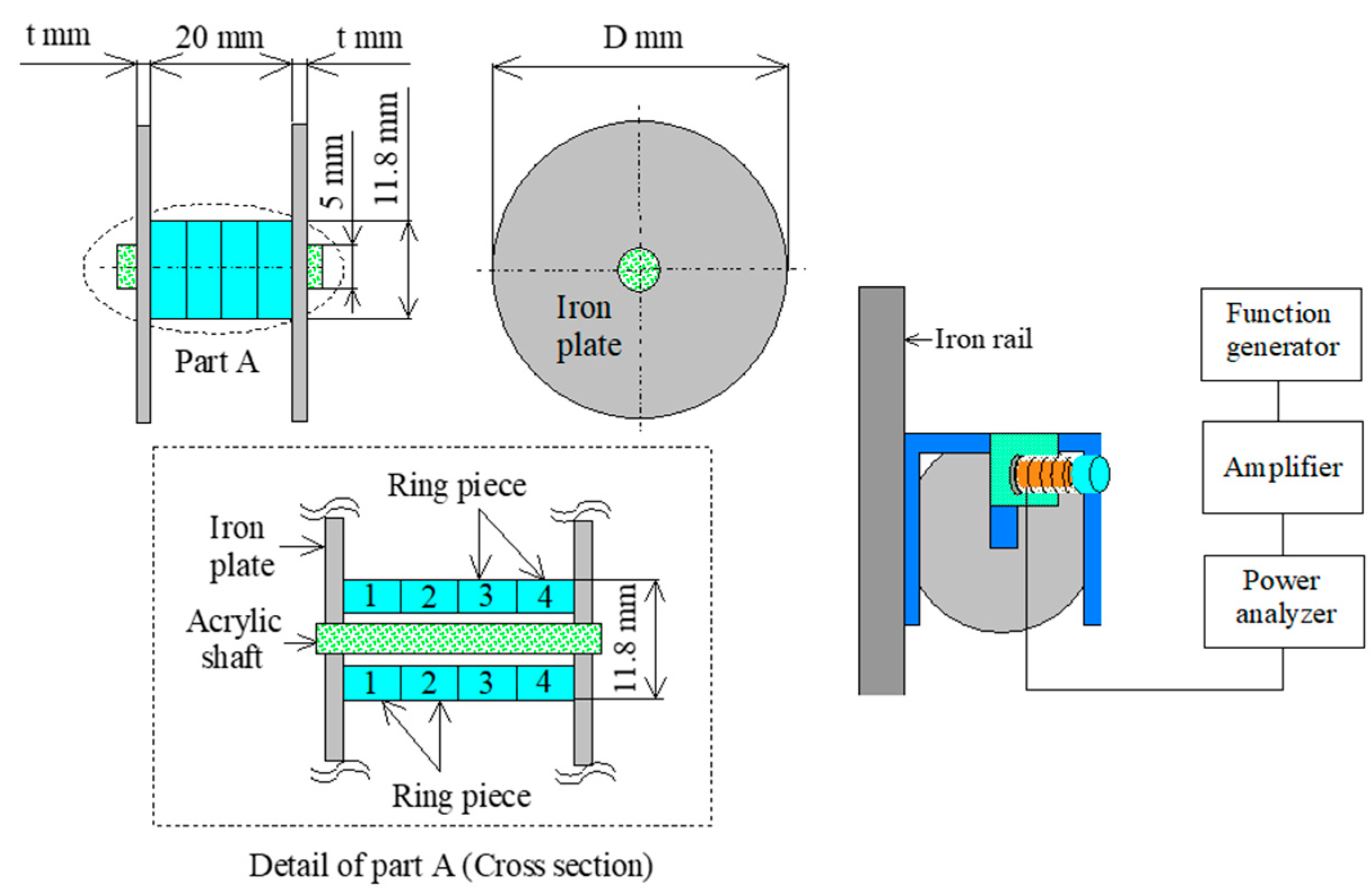
In this actuator system, a magnetic path is formed by the two iron disks and the iron structure being inspected. Therefore, the effect of the thickness and diameter of the two iron disks and the material of the four magnetic rings attached to the center of the disk on the attractive force was investigated, as shown in Figure 8 and Figure 9. Figure 8 also gives an overview of the experimental apparatus.
The attractive force between the two iron disks and the iron structure has a great influence on the movement characteristics of the actuator system. In this actuator system, a magnetic circuit is constituted by two iron disks, four ring pieces, and an iron structure. For this reason, leakage of the magnetic flux of the permanent magnet is prevented reduced to a minimum, and an effective attractive force is generated. Magnetic materials were used for all four ring pieces.
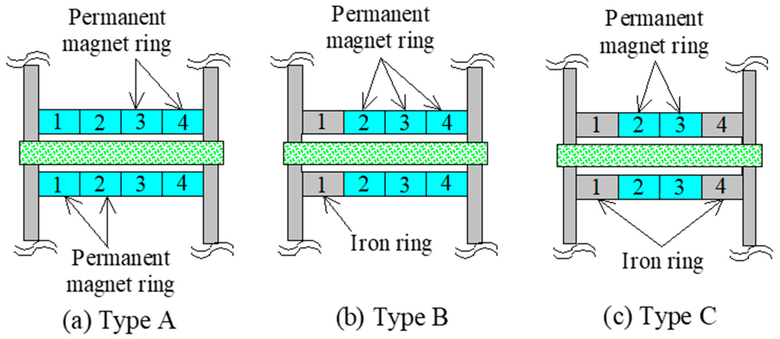
Figure 9 shows the three conditions considered in the evaluation of the effect of the material of the four magnetic rings. Type A has four permanent magnet rings of the same size, type B has three permanent magnets and one iron ring, and type C has two permanent magnets and two iron rings. The permanent magnet and iron rings have an outer diameter of 11 mm, an inner diameter of 7.8 mm, and a width of 5 mm. Additionally, the arrangement of the four rings in each type was as shown in Figure 9. The permanent magnet ring is made of NdFeB and is magnetized in the axial direction. The surface magnetic flux density measured using a Tesla meter was 396 mT. The effect of the dimensions of the iron disks was also evaluated. Thicknesses of 1, 1.5, and 2 mm, and diameters of 40, 50, and 60 mm were considered in this evaluation. E-shaped acrylic frames were produced with dimensions corresponding to the considered diameters of the iron disk.
Prior to the measurement of the attractive force, the total mass of the magnetic-wheel-type actuator system with the two vibration-type actuators was measured. Table 1 gives the total mass of the type A system with two vibration-type actuators for each combination of the considered diameters and thicknesses of the iron disks. As the thickness of the iron disk increases, the total mass of the actuator system increases sharply.
The force of the attraction of each type of magnetic wheel to the iron rail was measured using a spring balance. Table 2 gives the attractive force of each system type for iron disks with different thicknesses and a diameter of 40 mm. For each type, the attractive forces of the iron disks with thicknesses of 1.5 and 2 mm were very similar. Considering the tradeoff between the total weight of the actuator system and the need for a relatively strong attractive force when moving over a structure, a disk thickness of 1.5 mm was selected.
For the actuator system with the two vibration-type actuators shown in Figure 1, Table 3 gives the speed of the actuator system in the horizontal direction for different iron disk diameters when the power input to the electromagnet of one vibration-type actuator was set to 100 mW. The type A actuator system with a disk diameter of 40 mm achieved the highest speed among the considered cases. In this measurement, the driving frequency of the actuator system was 97 Hz.
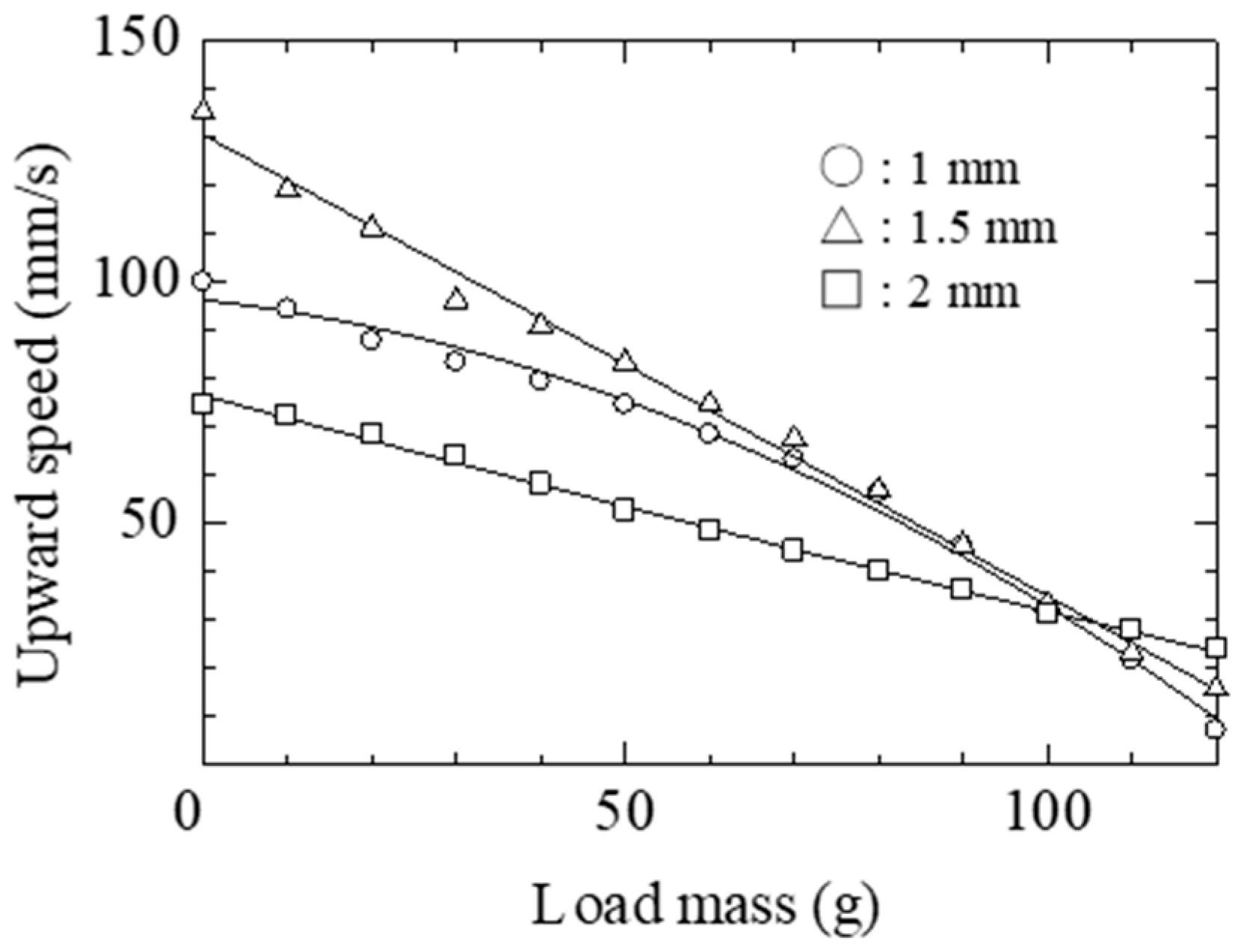
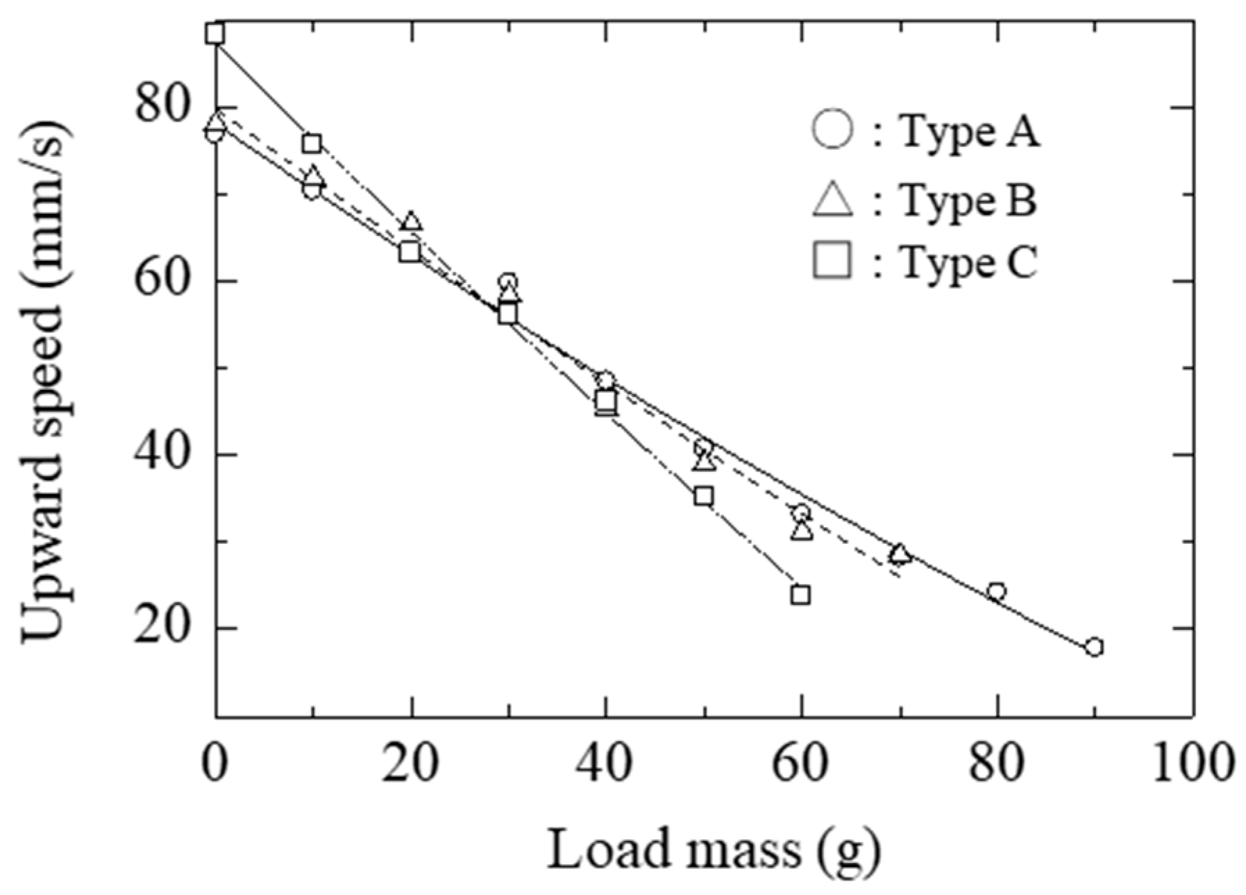
In this study, the magnetic wheel actuator system with a disk of 40 mm in diameter and 1.5 mm in thickness was adopted. Figure 10 shows the relationship between the mass loaded on the actuator system and the upward speed for the type A actuator with different iron disk thicknesses. In the measurement, the power input to the electromagnet was set to 685 mW. Even under a load mass of 120 g mounted on the actuator system, vertical upward movement at a speed of 24 mm/s was possible on the magnetic surface.
Figure 11 shows the relationship between the mass loaded on the actuator system and the upward speed for each magnetic ring configuration. In this measurement, the power input to the electromagnet was set to 367 mW. The type A actuator system showed excellent traction properties.
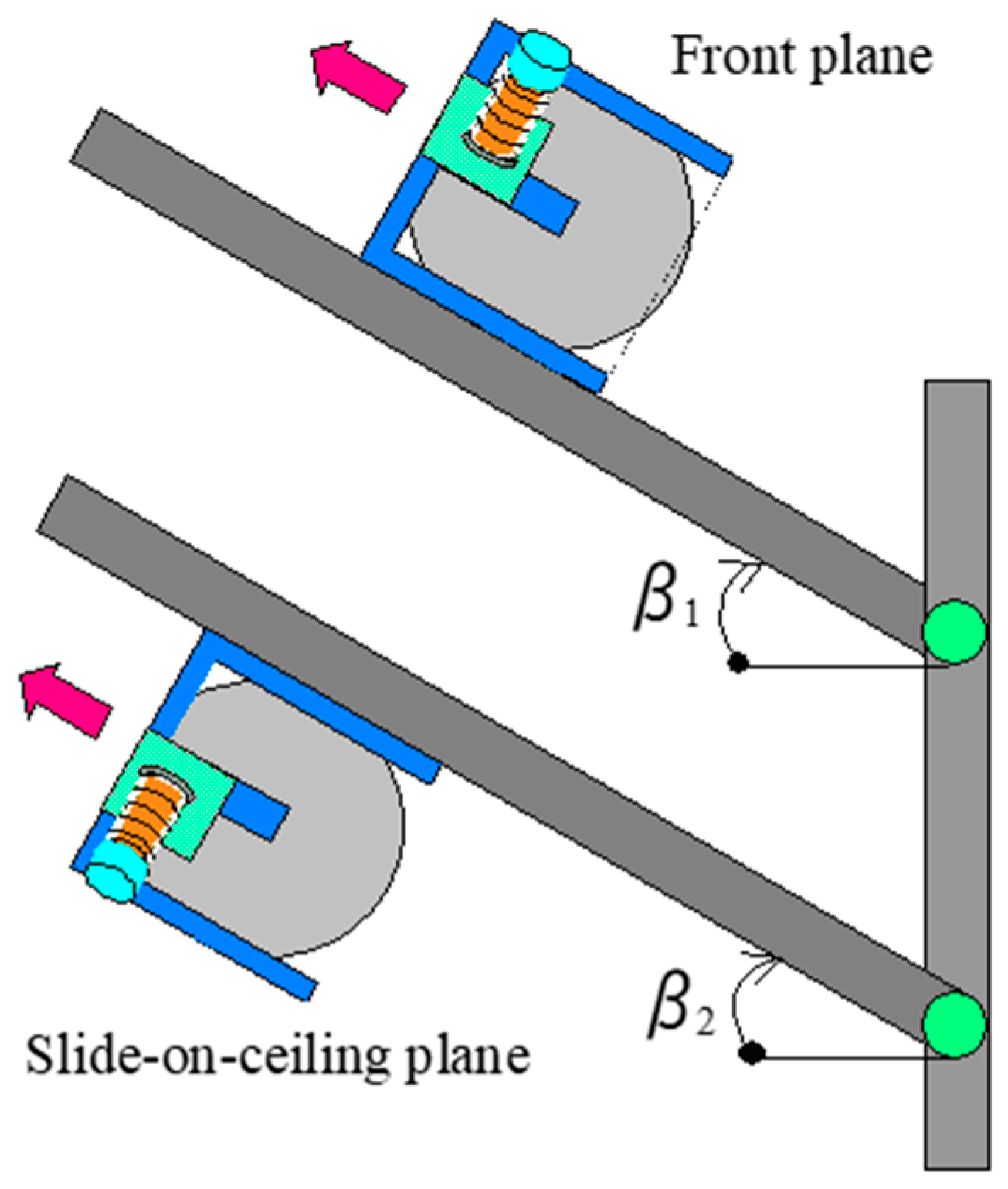
The effect of the tilt angle of the iron structure on the actuator system speed was then studied. Figure 12 shows the definition of the tilt angle β and the two cases that were considered in investigating its effect on the speed. The tilt angle was varied, and the actuator system speed was measured in the case of motion along the front and slide-on-ceiling planes of the iron rail.
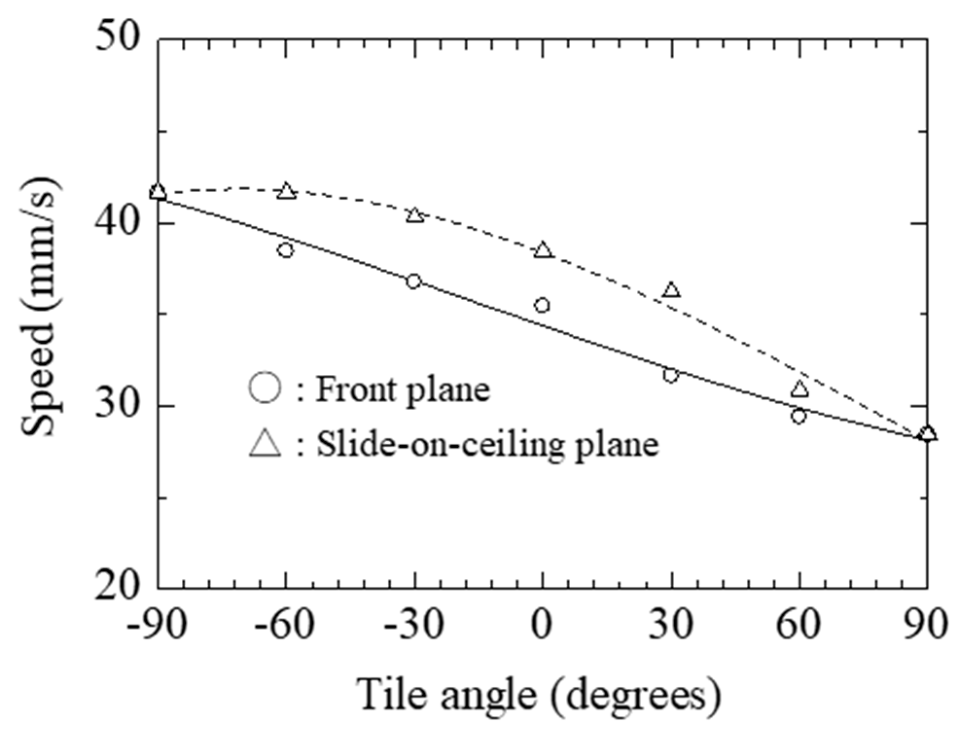
Figure 13 shows the speed of the actuator plotted against the angles β1 and β2 of the iron rail with respect to the horizontal plane under an input power of 150 mW. In this figure, the solid line and dashed lines represent variation in β1 and β2, respectively, as defined in Figure 11. The tilt angles β1 and β2 were varied from −90° (straight downward) to 90° (straight upward). In this figure, β1 corresponds to movement along the front plane, and β2 corresponds to movement along the slide-on-ceiling plane. Since the attractive force F of the support part changes as a result of the influence of the weight of the actuator system, for β1 = β2 = 0°, the speeds of the two movement types are different. In addition, for β1 = β2 = 90°, the movement is equivalent to the wall-climbing movement.
5. Turning Properties of the Actuator System
In this actuator system, movement is limited to one direction by its movement principle. Two SMA (TOKI Corporations, Trademark: BioMetal, 143-0006, 4-1-23 Heiwajima, Tokyo, Japan) coils and two friction pads were incorporated into the magnetic-wheel-type actuator system, and its ability to execute turning operations was examined. Figure 14 shows an overview of the actuator system capable executing turning operations. An SMA coil spring and a friction pad were respectively attached to rods A and B, forming the E-shaped acrylic frame via a conductor. Table 4 gives the properties of the SMA coil spring. The length of the SMA coil spring, with no current flowing through it, is 40 mm.
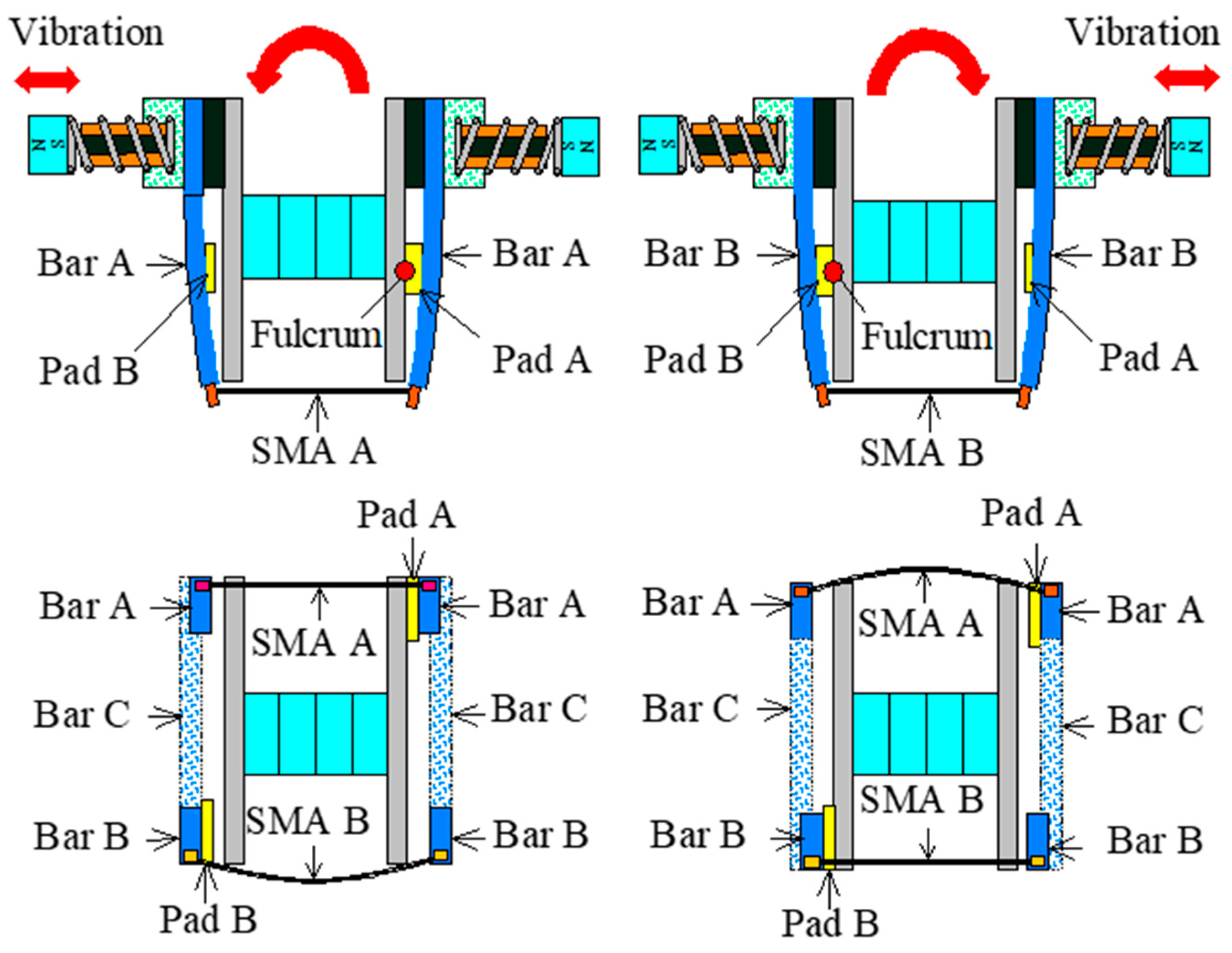
As shown in Figure 15, when a direct current is applied to the SMA coil spring by connection to a direct current (DC) power supply, the temperature of the SMA coil spring surpasses the transition temperature. The iron disk and the friction pad are then put into contact with each other by the contracted SMA coil spring, forming a fulcrum where the iron disk does not rotate. In this state, when vibration-type actuator B is operated, a moment is applied at the fulcrum, and the actuator system can turn in a clockwise direction. Since two SMA coil springs and two friction pads are employed in this setup, the actuator system can be turned clockwise or counterclockwise, depending on which SMA coil spring is contracted. In this way, the actuator system can move in any direction. In the measurement, the input power to the electromagnet of each vibration-type actuator was set to 405 mW.
Table 5 gives the clockwise and counterclockwise turning speeds when the horizontal and vertical planes are set as the plane of motion of the actuator system. The results given in this table demonstrate that the turning speeds in the counterclockwise or clockwise directions are approximately equal. The rotation speed in the vertical plane of motion (wall surface) is lower than that of the horizontal plane of motion. This is because the weight of the actuator system affects its movement in the vertical plane.
6. Conclusions
An actuator system combining two iron disks and two electromagnetic-vibration-type actuators was proposed and tested. The experimental results reveal that the proposed actuator system can pull 1.8 times of its own weight when the power input into the electromagnet is 685 mW. In addition, a configuration capable of turning operations combining SMA coil springs and friction pads was proposed. It was demonstrated that the actuator system is capable of turning in any direction. The actuator system can rotate at a rotation speed of 11 °/s, even if it is set on a vertical plane. The possibility of using such a system to perform the inspection of large structures was demonstrated. Future work will involve exploration of methods of improving the pulling characteristics and the step movement of the system and investigation of the coupling of multiple actuator systems.
Author Contributions
H.Y. initiated and supervised the development of the actuator and wrote the paper, I.K. and S.S. performed the development, design, assembly and integration of the prototype.
Conflicts of Interest
The authors declare no conflict of interest.
References
- Shen, W.; Gu, J.; Shen, Y. Permanent Magnetic System Design for the Wall-Climbing Robot. In Proceedings of the IEEE International Conference on Mechatronics & Automation, Beijing, China, 7–10 August 2011. [Google Scholar]
- Lee, G.; Park, J.; Kim, H.; Seo, T.W. Wall Climbing Robots with Track-wheel Mechanism. In Proceedings of the IEEE International Conference on Machine Learning and Computing, Guillin, China, 10–13 July 2011. [Google Scholar]
- Fukuda, T.; Matsuura, H.; Arai, F.; Nishibori, K.; Sakauchi, H.; Yoshi, N. A Study on Wall Surface Mobile Robots. Trans. Jpn. Soc. Mech. Eng. 1992, 58, 286–293. [Google Scholar]
- Kawasaki, S.; Kikuchi, K. Development of a Small Legged Wall Climbing Robot with Passive Suction Cups. In Proceedings of the International Conference on Design Engineering and Science, Pilsen, Czech Republic, 31 August–3 September 2014. [Google Scholar]
- Yoshida, Y.; Ma, S. A Wall-Climbing Robot without any Active Suction Mechanisms. In Proceedings of the IEEE International Conference on Robotics and Biomimetics, Karon Beach, Thailand, 7–11 December 2011. [Google Scholar]
- Miyake, T.; Ishihara, H.; Yoshimura, M. Basic Studies on Wet Adhesion System for Wall Climbing Robot. In Proceedings of the IEEE/RSJ International Conference on Intelligent Robots and Systems, San Diego, CA, USA, 29 October–2 November 2007. [Google Scholar]
- Apostolescu, T.C.; Udrea, C.; Duminica, D.; Ionascu, G.; Bogatu, L.; Cartal, L.A. Development of a Climbing Robot with Vacuum Attachment Cups. In Proceedings of the International Conference on Innovations, Recent Trends and Challenges in Mechatronics, Bucharest, Romania, 22–23 September 2011. [Google Scholar]
- Akhtaruzzaman, M.; Samsuddin, N.; Umar, N.; Rahman, M. Design and Development of a Wall Climbing Robot and its Control System. In Proceedings of the International Conference on Computer and Information Technology, Dhaka, Bangladesh, 21–23 December 2009. [Google Scholar]
- Suzuki, M.; Hirose, S. Proposal of Swarm Type Wall Climbing Robot System Anchor Climber and Development of Adhering Mobile Units. Robot. Soc. Jpn. 2010, 28, 614–623. [Google Scholar] [CrossRef]
- Khirade, N.; Sanghi, R.; Tidke, D. Magnetic Wall Climbing Devices—A Review. In Proceedings of the International Conference on Advances in Engineering & Technology, Singapore, 29–30 March 2014. [Google Scholar]
- Kim, J.H.; Park, S.M.; Kim, J.H.; Lee, J.Y. Design and Experimental Implementation of Easily Detachable Permanent Magnet Reluctance Wheel for Wall-Climbing Mobile Robot. J. Magn. 2010, 15, 128–131. [Google Scholar] [CrossRef] [Green Version]
- Yoon, K.H.; Park, Y.W. Controllability of Magnetic Force in Magnetic Wheels. IEEE Trans. Magn. 2012, 48, 4046–4049. [Google Scholar] [CrossRef]
- Kim, H.; Kim, D.; Yang, H.; Lee, K.; Seo, K.; Chang, D.; Kim, J. Development of a wall-climbing robot using a tracked wheel mechanism. J. Mech. Sci. Technol. 2008, 22, 1490–1498. [Google Scholar] [CrossRef]
- Subramanyam, A.; Mallikarjuna, Y.; Suneel, S.; Kumar, L.B. Design and Development of a Climbing Robot for Several Applications. Int. J. Adv. Comput. Technol. 2011, 3, 15–23. [Google Scholar]
- Panich, S. Development of a Climbing Robot with Vacuum Attachment Cups. J. Comput. Sci. 2010, 6, 1185–1188. [Google Scholar] [CrossRef]
- Jae-Uk, S.; Donghoon, K.; ong-Heon, J.; Hyun, M. Micro aerial vehicle type wall-climbing robot mechanism. In Proceedings of the IEEE RO-MAN International Symposium on Robot and Human Interactive Communication, Gyeongju, Korea, 26–29 August 2013. [Google Scholar]
- Wang, K.; Wang, W.; Li, D.; Zong, G.; Zhang, H.; Zhang, J.; Deng, Z. Analysis of Two Vibrating Suction Methods. In Proceedings of the IEEE International Conference on Robotics and Biomimetics, Bangkok, Thailand, 22–25 February 2009. [Google Scholar]
- Wang, W.; Wang, K.; Zhang, H.; Zhang, J. Internal Force Compensating Method for Wall-Climbing Caterpillar Robot. In Proceedings of the IEEE International Conference on Robotics and Automation, Anchorage, AK, USA, 3–7 May 2010. [Google Scholar]
- Xu, F.; Wang, X.; Jiang, G. Design and Analysis of a Wall-Climbing Robot Based on a Mechanism Utilizing Hook-Like Claws. Int. J. Adv. Rob. Syst. 2012, 9, 1–12. [Google Scholar] [CrossRef]
- Funatsu, M.; Kawasaki, Y.; Kawasaki, S.; Kikuchi, K. Development of cm-scale Wall Climbing Hexapod Robot with Claws. In Proceedings of the International Conference on Design Engineering and Science, Pilsen, Czech Republic, 31 August–3 September 2014. [Google Scholar]
- Provancher, W.; Jensen-Segal, S.; Fehlberg, M. ROCR: An Energy-Efficient Dynamic Wall-Climbing Robot. IEEE Trans. Mechatron. 2011, 16, 897–906. [Google Scholar] [CrossRef]
- Kute, C.; Murphy, M.; Menguc, Y.; Sitti, M. Adhesion Recovery and Passive Peeling in a Wall Climbing Robot using Adhesives. In Proceedings of the IEEE International Conference on Robotics and Automation, Anchorage, AK, USA, 3–7 May 2010. [Google Scholar]
- Unver, O.; Sitti, M. Tankbot: A Miniature, Peeling Based Climber on Rough and Smooth Surfaces. In Proceedings of the IEEE International Conference on Robotics and Automation, Kobe, Japan, 12–17 May 2009. [Google Scholar]
- Yaguchi, H.; Sakuma, S. A Novel Magnetic Actuator Capable of Free Movement on a Magnetic Substance. IEEE Trans. Magn. 2015, 51, 8206204. [Google Scholar] [CrossRef]
- Yaguchi, H.; Sakuma, S. Vibration Actuator Capable of Movement on Magnetic Substance Based on New Motion Principle. J. Vibroeng. 2017, 19, 1494–1508. [Google Scholar]
Figure 1.
Structure of the vibration-type actuator.

Figure 2.
Principle of linear locomotion.

Figure 3.
Speed of upward motion plotted against input power for two different load masses.

Figure 4.
Speed of upward motion plotted against tilt angle for two different input powers.

Figure 5.
Structure of magnetic-wheel-type actuator system.

Figure 6.
Photograph of magnetic actuator system and parts and assembly.

Figure 7.
Principle of locomotion.

Figure 8.
Details of magnetic-wheel-type actuator system and experimental apparatus.

Figure 9.
Experimental conditions to evaluate the effect of the material of the magnetic rings.

Figure 10.
Upward speed plotted against load mass for different iron disk thicknesses.

Figure 11.
Upward speed plotted against load mass for different magnetic ring configurations.

Figure 12.
Experimental setup to measure the effect of the tilt angle of the iron rail on the speed of the magnetic-wheel-type actuator system for motion in the front and slide-on-ceiling planes.
Figure 12.
Experimental setup to measure the effect of the tilt angle of the iron rail on the speed of the magnetic-wheel-type actuator system for motion in the front and slide-on-ceiling planes.

Figure 13.
Speed of the actuator system in the two considered planes of motion plotted against the tilt angle β of the iron rail.
Figure 13.
Speed of the actuator system in the two considered planes of motion plotted against the tilt angle β of the iron rail.

Figure 14.
Magnetic-wheel-type actuator system capable of turning operation.

Figure 15.
Principle of turning operation.


Table 1.
Total mass of the type A magnetic-wheel-type actuator system for different diameters and thicknesses of the iron disks.
Table 1.
Total mass of the type A magnetic-wheel-type actuator system for different diameters and thicknesses of the iron disks.
| Diameter (mm) | Total Mass (g) | ||
|---|---|---|---|
| Thickness: 1 mm | Thickness: 1.5 mm | Thickness: 2 mm | |
| 40 mm | 56.4 | 66 | 75.64 |
| 50 mm | 73.5 | 83.1 | 92.7 |
| 60 mm | 103.8 | 113.4 | 123 |
Table 2.
Attractive force of magnetic-wheel-type actuator systems with different disk thicknesses (disk diameter: 40 mm).
Table 2.
Attractive force of magnetic-wheel-type actuator systems with different disk thicknesses (disk diameter: 40 mm).
| Magnetic Ring | Attractive Force (N) | ||
|---|---|---|---|
| Thickness: 1 mm | Thickness: 1.5 mm | Thickness: 2 mm | |
| Type A | 9.3 | 15.1 | 16 |
| Type B | 9 | 14.9 | 15 |
| Type C | 8.9 | 14.3 | 14.8 |
Table 3.
Horizontal speed of magnetic-wheel-type actuator system types with different disk diameters.
Table 3.
Horizontal speed of magnetic-wheel-type actuator system types with different disk diameters.
| Diameter (mm) | Speed (mm/s) | ||
|---|---|---|---|
| Type A | Type B | Type C | |
| 40 mm | 41.7 | 37.9 | 34.5 |
| 50 mm | 35.77 | 32.1 | 30.3 |
| 60 mm | 29.1 | 26.7 | 25 |
Table 4.
Properties of the shape memory alloy (SMA) coil spring.
| Outer Diameter | Diameter of Wire | Transformation Point | Resistance per Meter | Input Current | |
|---|---|---|---|---|---|
| SMA coil spring | 0.62 mm | 150 μm | 60–65 °C | 400 Ω | 180 mA |
Table 5.
Turning speed of magnetic-wheel-type actuator system in the vertical and horizontal planes.
Table 5.
Turning speed of magnetic-wheel-type actuator system in the vertical and horizontal planes.
| Vertical Plane | Horizontal Plane | ||
|---|---|---|---|
| Clockwise (°/s) | Counter Clockwise (°/s) | Clockwise (°/s) | Counter Clockwise (°/s) |
| 12 | 11 | 20 | 21 |
© 2019 by the authors. Licensee MDPI, Basel, Switzerland. This article is an open access article distributed under the terms and conditions of the Creative Commons Attribution (CC BY) license (http://creativecommons.org/licenses/by/4.0/).
Share and Cite
MDPI and ACS Style
Yaguchi, H.; Kimura, I.; Sakuma, S. A Novel Actuator System Combining Mechanical Vibration and Magnetic Wheels Capable of Rotational Motion Using Shape Memory Alloy Coils. Actuators 2019, 8, 4. https://doi.org/10.3390/act8010004
AMA Style
Yaguchi H, Kimura I, Sakuma S. A Novel Actuator System Combining Mechanical Vibration and Magnetic Wheels Capable of Rotational Motion Using Shape Memory Alloy Coils. Actuators. 2019; 8(1):4. https://doi.org/10.3390/act8010004
Chicago/Turabian StyleYaguchi, Hiroyuki, Izuru Kimura, and Shun Sakuma. 2019. "A Novel Actuator System Combining Mechanical Vibration and Magnetic Wheels Capable of Rotational Motion Using Shape Memory Alloy Coils" Actuators 8, no. 1: 4. https://doi.org/10.3390/act8010004
Note that from the first issue of 2016, this journal uses article numbers instead of page numbers. See further details here.