Development of a Self-Powered Magnetorheological Damper System for Cable Vibration Control


1
School of Civil Engineering and Communication, North China University of Water Resources and Electric Power, Zhengzhou 450045, China
2
Key Laboratory for Wind and Bridge Engineering of Hunan Province, Hunan University, Changsha 410082, China
3
Key Laboratory of Concrete and Prestressed Concrete Structure of Ministry of Education, Southeast University, Nanjing 210096, China
*
Author to whom correspondence should be addressed.
Appl. Sci. 2018, 8(1), 118; https://doi.org/10.3390/app8010118
Submission received: 22 November 2017
/
Revised: 24 December 2017
/
Accepted: 10 January 2018
/
Published: 15 January 2018
(This article belongs to the Special Issue Development and Application of Nonlinear Dissipative Device in Structural Vibration Control)
Abstract
:A new self-powered magnetorheological (MR) damper control system was developed to mitigate cable vibration. The power source of the MR damper is directly harvested from vibration energy through a rotary permanent magnet direct current (DC) generator. The generator itself can also serve as an electromagnetic damper. The proposed smart passive system also incorporates a roller chain and sprocket, transforming the linear motion of the cable into the rotational motion of the DC generator. The vibration mitigation performance of the presented self-powered MR damper system was evaluated by model tests with a 21.6 m long cable. A series of free vibration tests of the cable with a passively operated MR damper with constant voltage, an electromagnetic damper alone, and a self-powered MR damper system were performed. Finally, the vibration control mechanisms of the self-powered MR damper system were investigated. The experimental results indicate that the supplemental modal damping ratios of the cable in the first four modes can be significantly enhanced by the self-powered MR damper system, demonstrating the feasibility and effectiveness of the new smart passive system. The results also show that both the self-powered MR damper and the generator are quite similar to a combination of a traditional linear viscous damper and a negative stiffness device, and the negative stiffness can enhance the mitigation efficiency against cable vibration.
1. Introduction
Due to high flexibility, low inherent damping, and relative small mass, long stay cables are often susceptible to excessive vibrations under various environmental excitations. Large oscillations may result in undue stresses or fatigue failure in cables or connections, which is detrimental to the serviceability and safety of the entire cable-stayed bridge. Hence, it is of great importance to mitigate cable vibrations. Transversely attached dampers near the anchorage of the cable are one of the most common solutions to this problem. However, the performance of passive viscous dampers in mitigating cable vibration is greatly restricted by the small ratio of the distance from the cable anchorage to the damper over the length of the cable [1]. This may cause the supplemental damping induced by a passive damper to be insufficient to eliminate the problematic vibrations of long stay cables without significantly detracting from the aesthetics of the bridge.
As a more promising solution, semi-active control has been proposed to enhance performance since it offers the capability of active control devices without the requirement of large power resources [2]. In particular, magnetorheological (MR) dampers have attracted extensive attention from the community because of their excellent performance in both lab tests and engineering practice [3,4,5,6,7,8,9,10]. To date, MR dampers have been implemented for full-scale applications, including the stay cables on the Dongting Lake Bridge [11], Binzhou Bridge [12], and Sutong Bridge [13]. Nevertheless, these control systems need external power supplies and/or sensors/controllers, which seem to be too costly and complex.
Energy harvesting from structural vibrations is a potential solution to the power supply problem of MR dampers [14,15,16]. In civil engineering, electromagnetic energy harvesting shows superiority over other mechanisms [17,18], such as piezoelectricity [19], electrostatic generation [20], and dielectric elastomers [21]. Accordingly, a smart damping system, consisting of an MR damper and a linear electromagnetic generator, has been well developed and investigated by a number of researchers [22,23,24,25]. However, the energy harvesting capability of a linear generator is quite limited [26]. In view of energy harvesting efficiency, self-powered MR dampers based on rotary generators have also been proposed to enhance the energy harvesting efficiency [27,28].
In this paper, a self-powered MR damper system based on a rotary DC generator for cable vibration control is developed and experimentally investigated. It has been shown that two control devices (i.e., an MR damper and a rotary DC generator in this paper) at the same location of the stay cable will deteriorate the vibration mitigation performance [29,30]. Therefore, unlike previous compact self-powered MR dampers [23,27,28], the proposed system focuses on improving the vibration mitigation efficiency of the stay cable with little consideration to device compactness, where the MR damper and the rotary DC generator are separated rather than integrated into one compact device. In addition, a flexible chain–sprocket is selected as the linear-to-rotation conversion mechanism instead of rigid transmission mechanisms, such as the ball–screw [27] or the rack–pinion [31]. Consequently, the rotary DC generator can be installed at a higher location of the cable to provide more power to the MR damper.
The paper is organized as follows. First, a new self-powered MR damper system is proposed and constructed to suppress cable vibrations, and the energy harvesting performance of the rotary DC generator is highlighted. Next, vibration mitigation tests of a model cable attached with different kinds of dampers are conducted, including a passively operated MR damper with constant voltage, the electromagnetic damping alone due to the generator, and a self-powered MR damper system. The corresponding identified modal damping ratios in the first four modes of the cable are then compared and analyzed. The vibration mitigation mechanisms of the proposed self-powered MR damper system are also investigated.
2. Description of the Self-Powered MR Damper System for Cable Vibration Control
2.1. Configuration and Principle
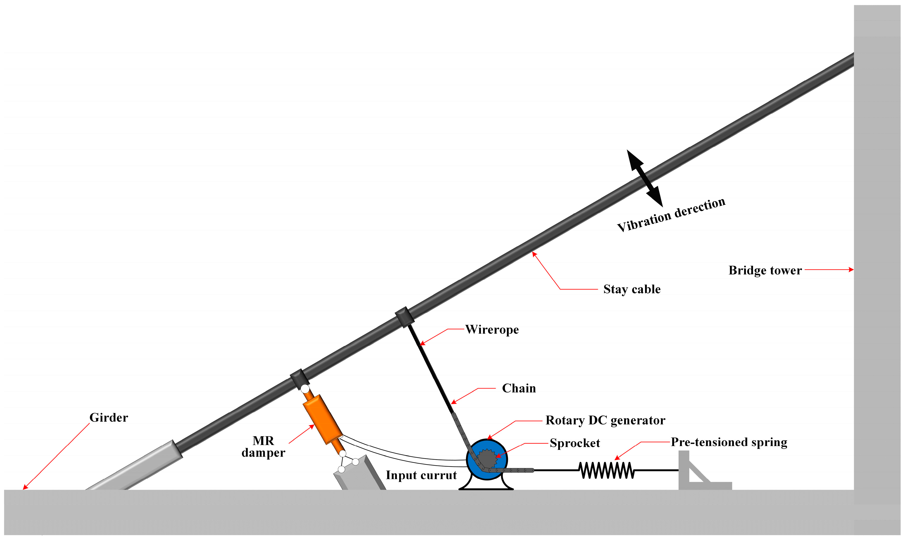
The proposed self-powered MR damper system consists of a current-adjusted MR damper and an energy harvesting device. Figure 1 depicts a schematic diagram of the system used in a real environmental setting for cable vibration control. The energy harvesting device includes a rotary DC generator and a linear-to-rotational conversion mechanism. The MR damper and the generator are attached to the cable at different locations rather than being integrated into one device. To improve the energy harvesting capability, the generator is attached at a higher location relative to the MR damper. Accordingly, the roller chain–sprocket is selected as the linear-to-rotational conversion mechanism since it can be conveniently installed at a higher location through a flexible connection without detracting from the aesthetics of the bridge.
Under environmental excitation, the reciprocating linear motion of the stay cable can be converted into the rotational motion of the rotary DC generator through the linear-to-rotational conversion mechanism and a pre-tensioned spring. Accordingly, the rotary DC generator will produce electromotive force (EMF), and the induced EMF/current is then used as an input to the MR damper. Consequently, cable vibration can be mitigated by the self-powered MR damper system. It is worth noting that there are two sources of damping in the self-powered MR damper system for suppressing cable vibration. The major one is the self-powered MR damper, and the other one is the electromagnetic damping due to the generator itself.
In addition, the EMF induced by the generator is proportional to the velocity of the stay cable [32], which implies that both the supply EMF/current and the damping force will increase with the increase in cable vibration. Consequently, the proposed self-powered MR damper system is expected to be capable of adaptively attenuating cable vibration without an external power supply or any controller. Nonetheless, the system is actually passive.
2.2. Linear-to-Rotational Conversion
To ensure that the reciprocating linear motion of the stay cable can be converted into the bidirectional rotational motion of the sprocket and the rotary DC generator, a pre-tensioned spring is connected to the chain to guarantee that the chain is able to move back and forth with the cable (Figure 1). The stiffness coefficient of the spring should be suitable so that the chain can always keep straight without providing excessive extra tension force to the stay cable. In addition, the initial elongation of the spring should be larger than the predicted amplitude of the cable at the location of the generator. Thus, the linear motion of the cable is successfully translated into the rotational motion of the rotary DC generator. The relationship between the angular velocity of the generator and the linear velocity of the stay cable is given as
where η is the transmission efficiency of the linear-to-rotational conversion, expressed as
where r is the effective transmission radius of the sprocket.
2.3. Model and Test of a Rotary DC Generator
The equivalent circuit model of a rotary DC generator is depicted in Figure 2. The back EMF of the generator Vg is expressed as
where Ke denotes the back EMF constant.
According to Kirchhoff’s law, the voltage in the circuit should be in balance as follows:
where I denotes the current flow in the circuit; Lg and Rg represent the inductance and resistance of the generator, respectively; and RL s the load resistance in the circuit.
Applying the Laplace transform to Equations (3) and (4), the transfer function of the current I can be obtained using
where U(s) and I(s) are the Laplace transform of u(t) and I(t), respectively.
Equations (3)–(5) indicate that the amplitude of the current flow I is proportional to the back EMF coefficient Ke and the cable velocity at the generator location (i.e., displacement amplitude and frequency of the cable), while it is inversely proportional to the effective transmission radius of the sprocket.
Consequently, the output voltage Uoutput and the output power Poutput of the generator can be respectively given as
Equation (6) indicates that the output power of the generator is proportional to the square of the current flow in the circuit, which mainly relates to the square of the cable’s displacement amplitude and frequency at the location of the generator.
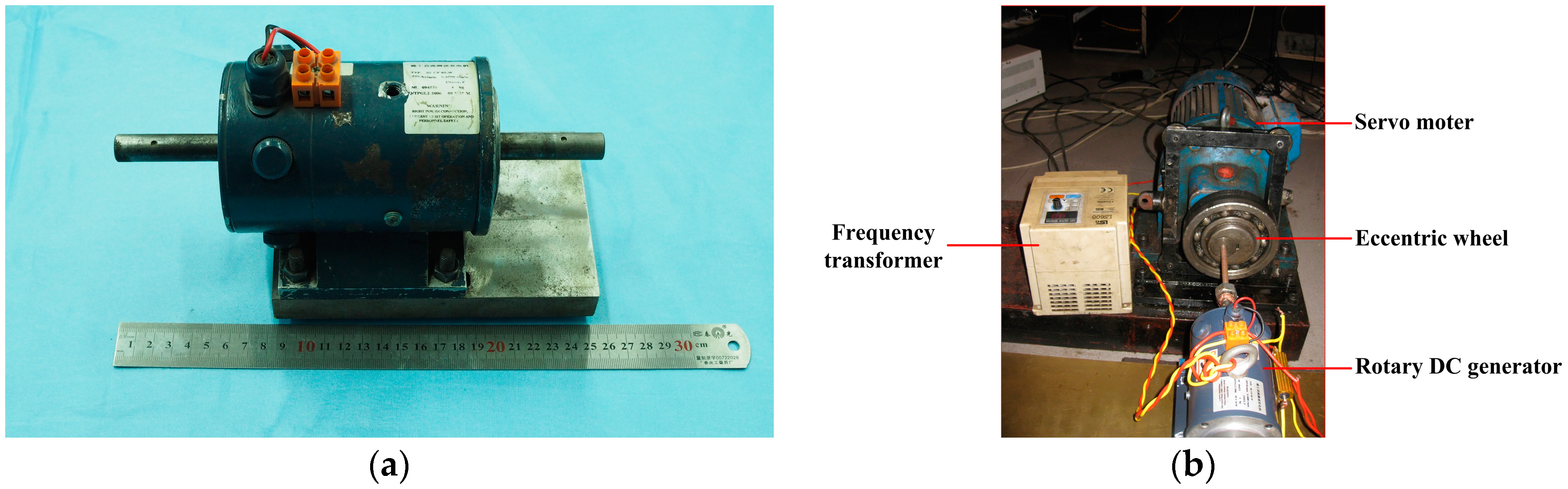
Experimental study on the rotary DC generator was conducted to illustrate its potential to provide the power supply for an MR damper. The rotary DC generator adopted in the test is a commercial CFX-04 speed-measuring permanent magnet DC motor, as shown in Figure 3a. The mass of the generator is 3.7 kg, and the maximum angular velocity can reach as much as 2800π/min. The internal resistance of the generator is 6.4 Ω.
To acquire the back EMF constant of the generator, the shaft of the generator was forced to rotate synchronously with a servomotor at different rotational speeds, as shown in Figure 3b. Figure 4 shows the relationship between the back EMF and the rotational speed of the generator. Finally, the back EMF constant Ke of the generator was identified as 0.0594 v/(r/min).
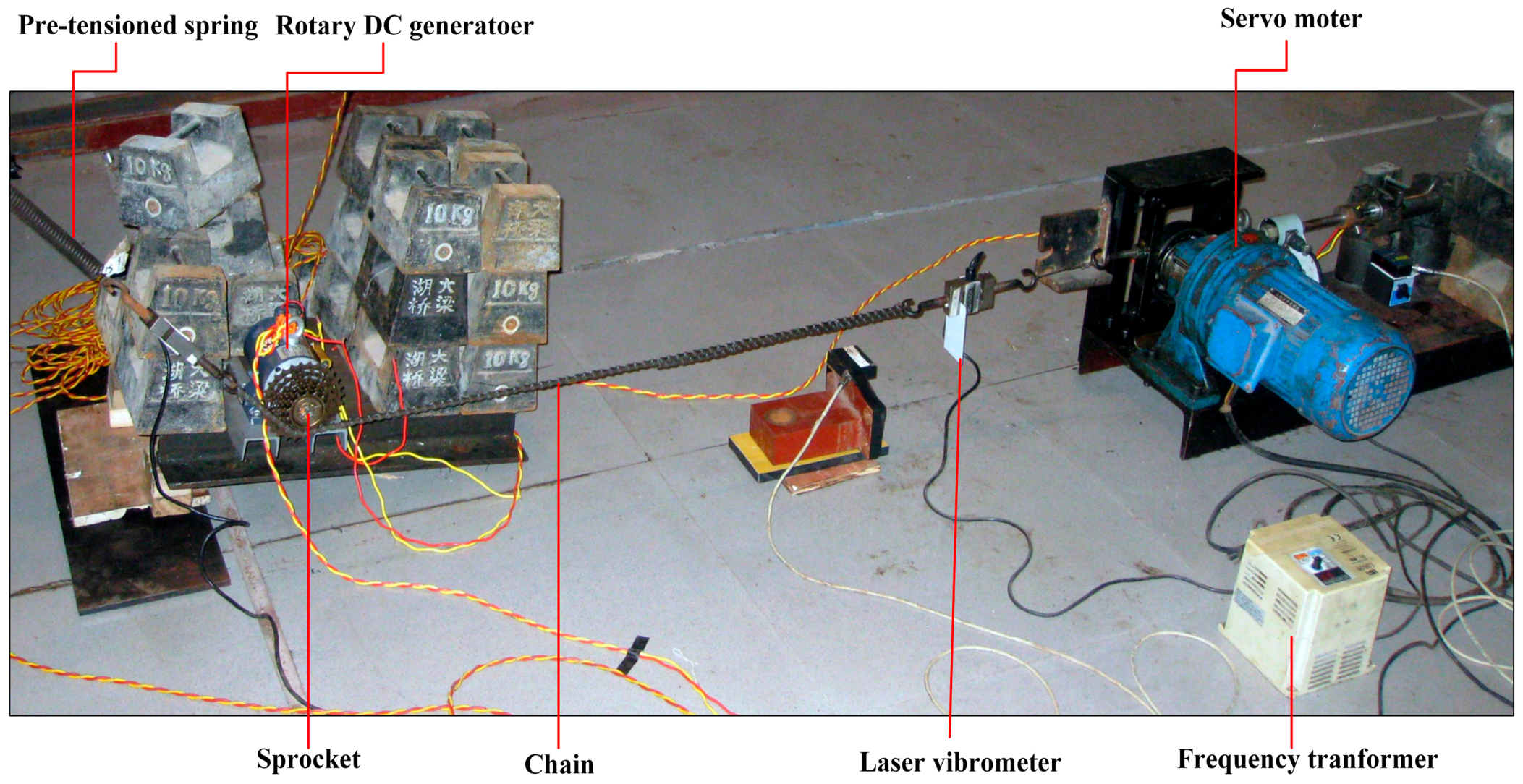
Next, the chain in the linear-to-rotational conversion mechanism was subjected to sinusoidal excitations with ten different frequencies ranging from 0.5 Hz to 5 Hz at amplitudes of 5 mm and 10 mm, respectively. The external load in the circuit was 15 Ω. The output voltage of the generator was measured. A laser vibrometer was used to monitor the linear displacement of the excitation. The corresponding experimental setup is shown in Figure 5, and all the data were recorded using the Donghua Data Acquisition System.
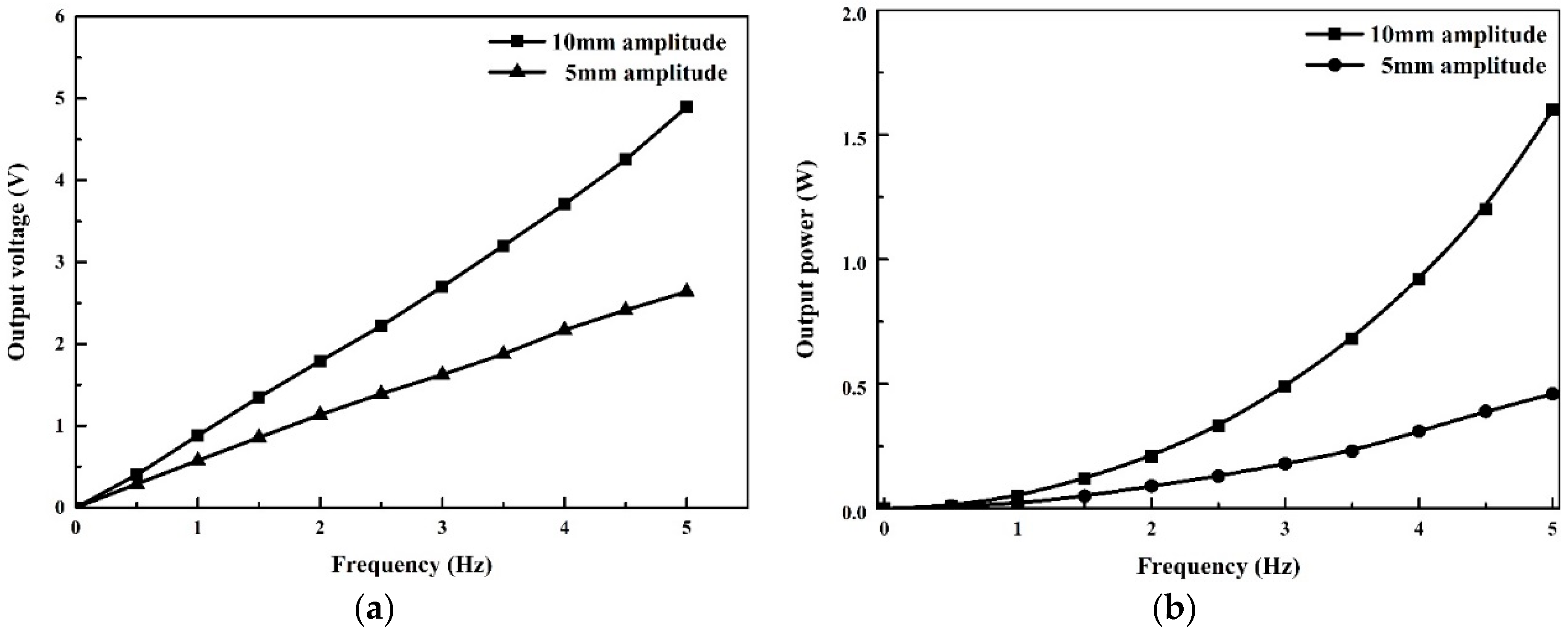
Figure 6a,b illustrate the relationship between the output voltage and the vibration frequency, and the relationship between the harvested electrical power and the vibration frequency, respectively. It is shown that both the output voltage and the output power are quite dependent on the frequency and the amplitude of the vibration source. Hence, it can be inferred that energy harvesting in civil engineering structures vibrating with low amplitudes and frequencies is quite challenging. However, the electrical energy harvested by the rotary DC generator in this paper is enough to provide a power supply to a small-scale MR damper with a low power requirement.
3. Experimental Setup
3.1. Experimental Platform
To evaluate the vibration control performance of the presented self-powered MR damper system, an experimental platform with a 21.6 m long scaled cable was established in the laboratory. Figure 7 illustrates the general layout of the experimental setup, while corresponding photos are shown in Figure 8. The main properties of the model cable are listed in Table 1. Lumped masses at 160 mm intervals were arranged along the cable to ensure that the model cable had similar dynamic characteristics with those on real cable-stayed bridges. The RD-1005-3 MR damper, manufactured by the Lord Corporation (Cary, NC, USA) (http:www.lord.com), was transversely attached 0.48 m (i.e., 2.2% of the cable length) from the end of the cable, incorporating a load cell and a displacement sensor to monitor the response of the MR damper. This damper type was once applied to suppress the cable vibration in the Dongting Lake Bridge [10]. The rotary DC generator was attached 1.08 m (i.e., 6% of the cable length) from the end of the cable; A laser vibrometer and a load cell were also attached to measure the linear displacement and the total force of the generator, respectively. The elastic force due to the pre-tensioned spring was also measured with a load cell. The output voltage of the DC generator applied to the MR damper was recorded. An accelerator was installed at 12.5% relative to the cable length to measure the cable acceleration, which was then adopted to identify the modal damping ratios of the cable.
3.2. Experimental Procedure and Data Processing
A series of free vibration tests were conducted to assess the performance of the self-powered MR damper system in terms of reducing cable vibration. Four test cases were considered, including an uncontrolled cable, a passively operated MR damper with constant voltage, the electromagnetic damping alone generated by the rotary DC generator, and the self-powered MR damper system.
The cable was excited manually at its natural frequencies in the first four modes, respectively. The excitation rope was not released until the amplitude of the vibration reached a certain level. To get a better acceleration signal with one target mode of the cable, the excitation position for the first two modes was located at 1/4l away from the anchorage of the cable, but was moved to 1/10l away from the anchorage for the third and the fourth modes. The acceleration signals at the evaluation measurement point were filtered through the band pass filter in MATLAB. Accordingly, the free decay acceleration curve of the cable with almost one single target mode was obtained, and the natural frequencies of the cable were directly identified via the time-domain method.
Generally, the modal damping ratios of structures can be identified using the logarithmic attenuation rate of free decay responses, which works well for exponentially decaying vibrations. However, the modal damping ratios of the cable may be dependent on the amplitude of the cable when the cable is equipped with nonlinear control devices, such as the passively operated MR dampers. The induced problem of amplitude-dependent damping ratio values when a nonlinear damper is attached to the cable has been well described in [33,34]. Nevertheless, except for the case of a passively operated MR damper with constant voltage, cable vibrations decay exponentially. Therefore, a uniform method to identify the modal damping ratios of a cable to which different control devices are attached needs to be defined to compare control performance. In this paper, the logarithmic decrement method was finally adopted, and the first 20 cycles from the same amplitude of free decay acceleration of the cable at the evaluation measurement point were selected to form an estimate of the damping ratios of the cable for each mode. The natural frequencies and modal damping ratios of an uncontrolled cable in the first four modes were identified, and are listed in Table 2.
4. Experimental Results and Discussion
4.1. The Stay Cable with a Passively Operated MR Damper
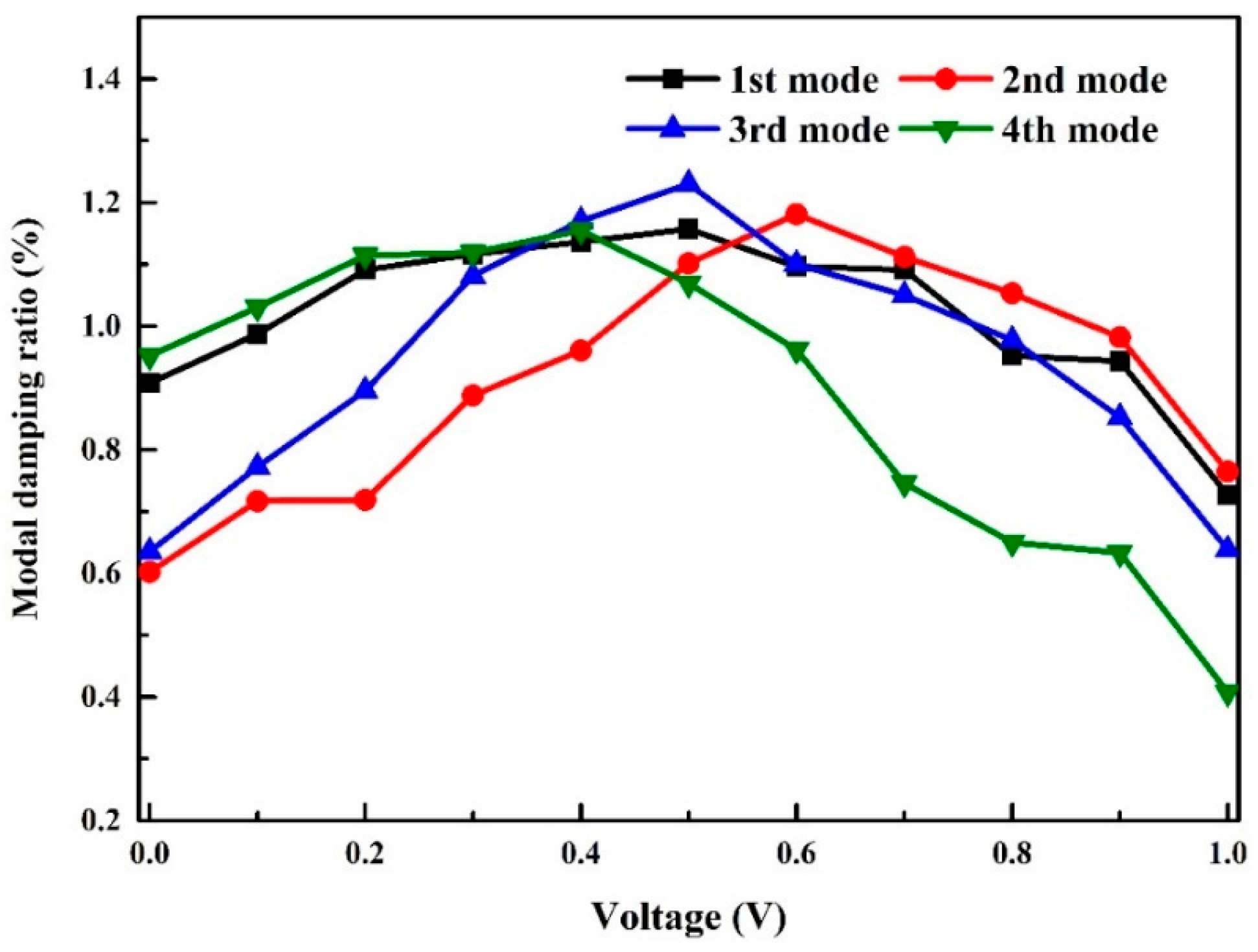
Figure 9 shows the modal damping ratios in the first four modes of the test cable controlled by a passively operated MR damper with constant voltage. As expected, there is an optimum voltage corresponding to a maximum modal damping ratio for each mode of the cable. Generally, lower voltage input seems to be better for a higher-order mode except for the first mode of the cable. In this study, 0.5 V was finally selected as the optimal constant voltage for the passively operated MR damper since it can perform quite well for all of the first four modes of the cable.
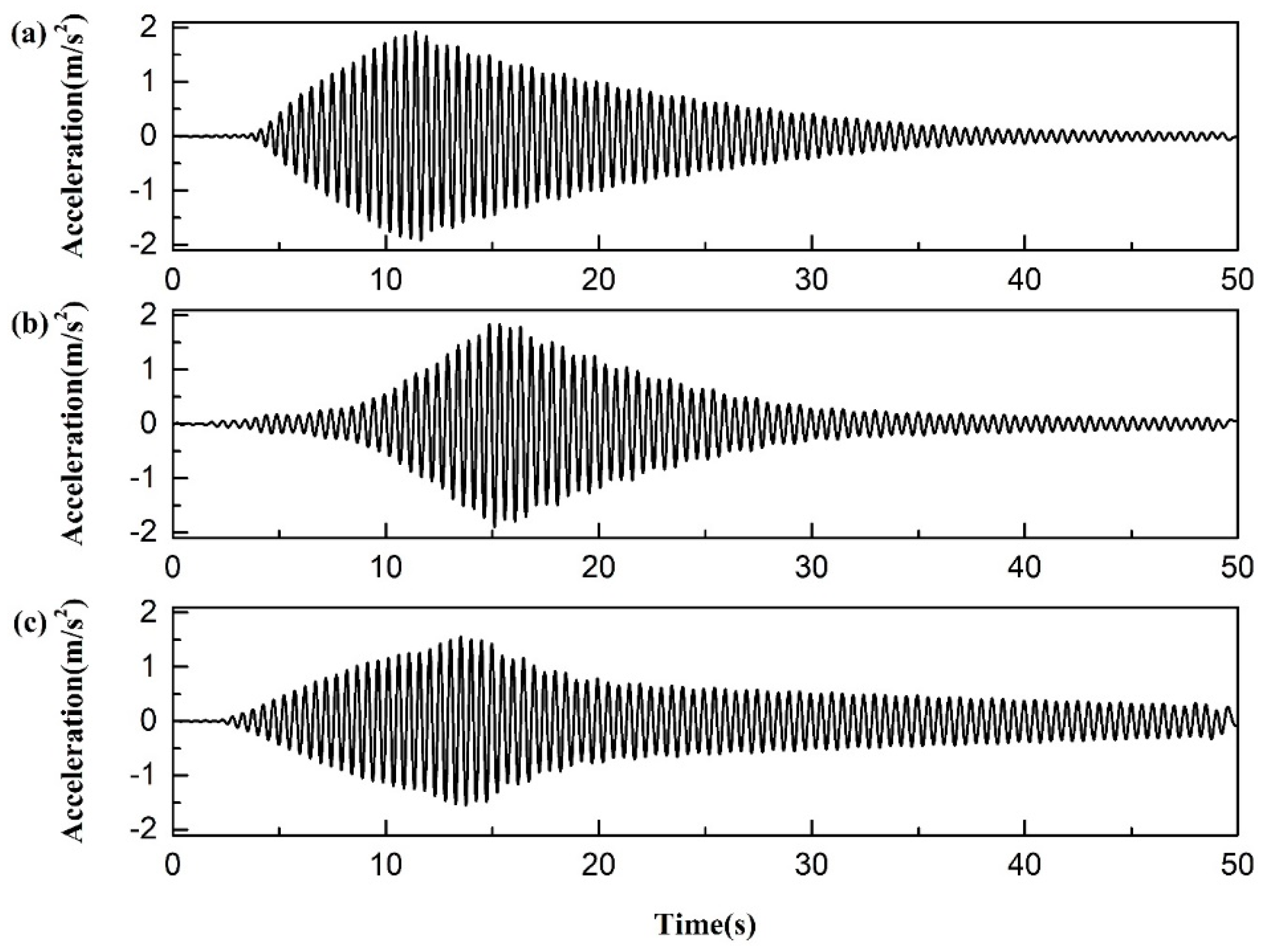
Taking the second mode of the cable as an example, the entire time histories of accelerations at the observation point of the cable with a passively operated MR damper attached are shown in Figure 10. It can be seen that acceleration amplitudes continuously increase with steady external excitation at the first stage, and then decay after the release of excitation. Figure 10 illustrates that the MR damper operated in passive-on mode (i.e., 1 V voltage) can only work well when the amplitude of the cable is relatively large. When the amplitude of the cable falls below one threshold, the MR damper may be locked and lose its energy dissipation capacity. As clearly shown in Figure 10c, the supplemental modal damping due to the MR damper gets quite small after 20 s. Therefore, the performance with a passive-on operated MR damper will be substantially reduced for the case of cable vibration with low amplitude. For the passive-off mode (i.e., 0 V voltage) of the MR damper, the acceleration amplitudes decay exponentially with a low damping ratio in all stages of the vibration, demonstrating amplitude-independent damping behavior. Hence, the MR damper operated in the optimal passive mode (i.e., 0.5 V voltage) may be a better choice as it has benefits from both the passive-on and passive-off modes.
4.2. The Stay Cable with Electromagnetic Damping Alone
To investigate the effect of electromagnetic damping alone on the vibration mitigation performance of the cable, two circuits of the generator were considered. One is a short circuit, and the other is loaded with an MR damper. However, the MR damper herein is not attached to the cable. The main difference between them is that the resulting equivalent damping coefficients for the case of the short circuit are larger than those for the other case.
The test results are summarized in Table 3, where the supplemental modal damping ratios are derived from the subtraction between the identified value with the electromagnetic damping and the uncontrolled case. It is noted that the supplemental damping ratio of the cable controlled by the electromagnetic damping alone is pretty limited, and the supplemental modal damping ratios of the same mode in the short circuit case are always larger than those in the circuit loaded with the MR damper. In addition, the supplemental modal damping ratio continuously increases with the increase of the mode order for both of the circuits. However, the supplemental modal damping ratio of the cable with the electromagnetic damping alone is much smaller than the theoretical maximum damping ratio induced by an ideal linear viscous damper (3%). This is mainly because the damping coefficient of the generator is much smaller than the corresponding optimum value. Therefore, the test results above imply that the generator can serve as an alternative damper for cable vibration control, and its efficiency can be further enhanced through optimum design of the generator system.
The relationship between the damping force and the linear displacement of the generator is shown in Figure 11. The damping characteristics of the generator are very similar to those of a combination of a traditional linear viscous damper and a negative stiffness device in the higher-order mode of the cable. It is noteworthy that the negative stiffness component of the generator is not visible in the 1st mode, which is mainly due to the fact that the negative stiffness of the generator for the 1st mode of the cable is smaller than its internal stiffness.
In fact, the total force Fg of the rotary DC generator can be divided into the inertial force FI and the electromagnetic damping force Fd [35]. This relationship can be expressed as
When the rotary DC generator is applied to mitigate cable vibration, we have
where kg, me, and ceq represent the equivalent stiffness, the inertial mass, and the damping coefficient of the generator, respectively; u and ωi denote the displacement and the natural frequency of the cable in the ith-order mode, respectively. The inertial mass is generated from the rotary part (i.e., rotor) of the generator.
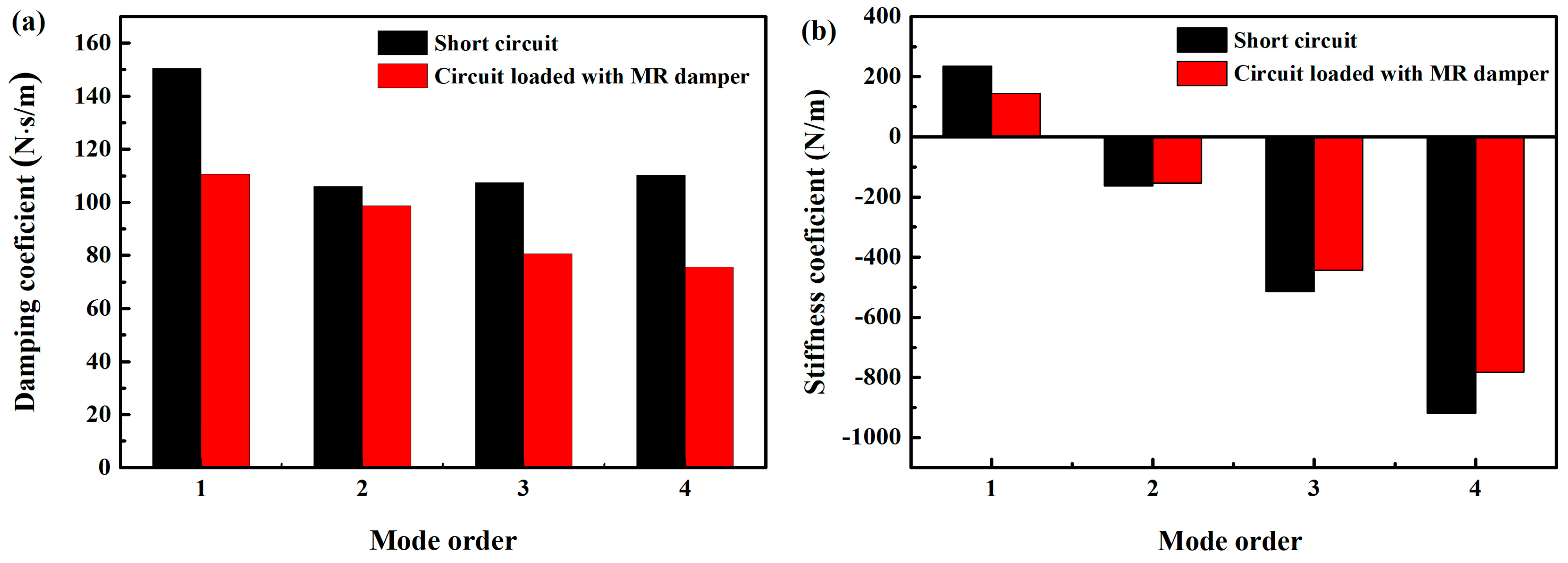
Equation (8) indicates that the negative stiffness of the rotary DC generator is proportional to the natural frequency of the cable, demonstrating frequency-dependent behavior. In other words, a higher mode of the cable corresponds to a larger negative stiffness. Accordingly, experimentally identified equivalent damping coefficients and stiffness coefficients are shown in Figure 12. As expected, the damping coefficient almost remains a constant with the increase of the mode order of the cable for each circuit, while the negative stiffness increases with the increase of the mode order. However, the optimum negative stiffness for a stay cable does not depend on the mode number [36,37]. Hence, the DC generator with frequency-dependent negative stiffness may be better than viscous damping only, but is still suboptimal when compared with optimum viscous damping with negative stiffness for cable vibration control.
4.3. The Stay Cable with a Self-Powered MR Damper System
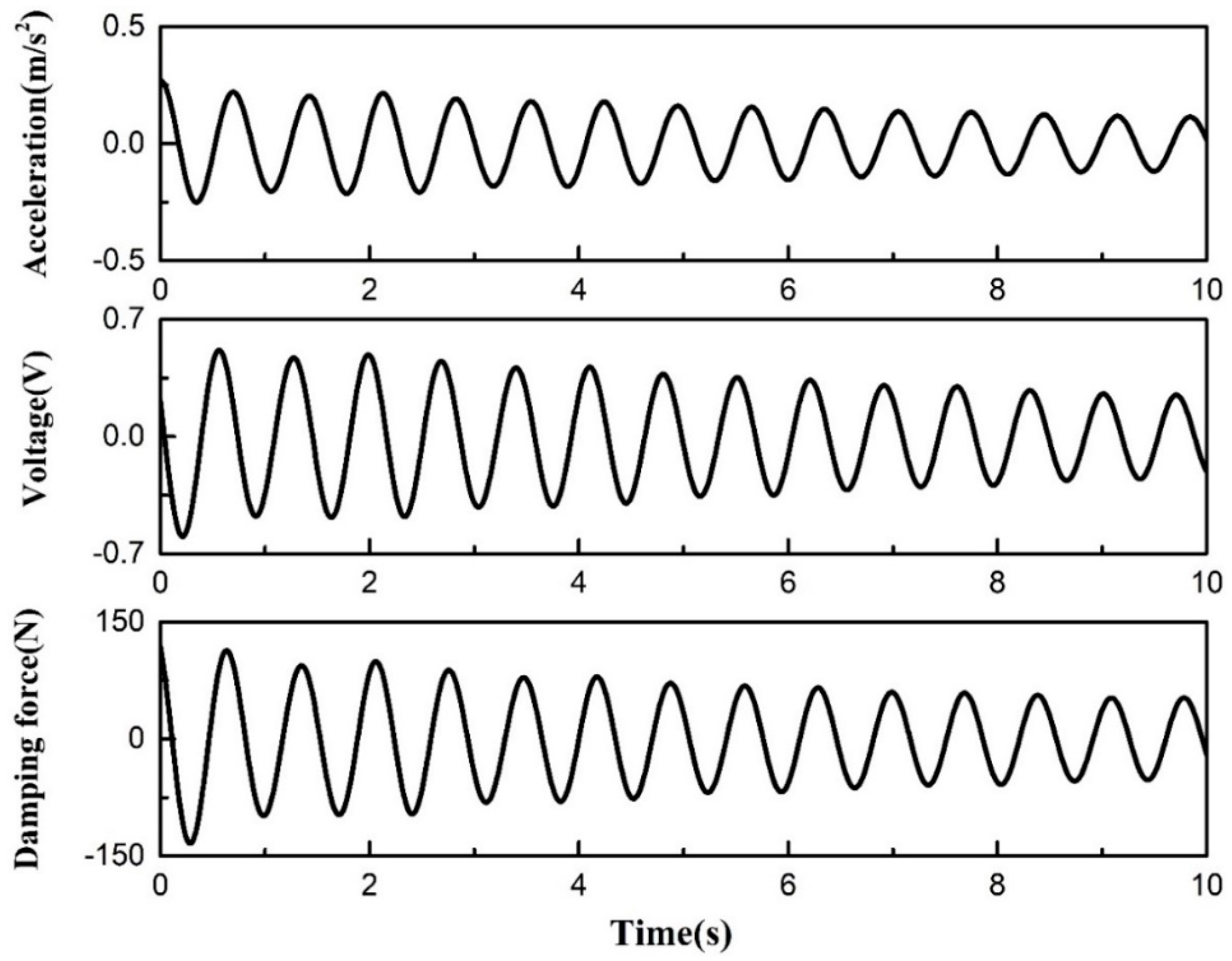
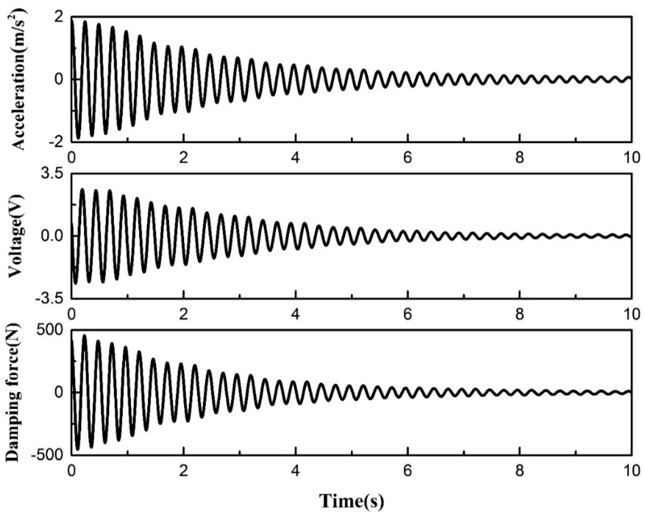
Figure 13 and Figure 14 give the time histories of the acceleration of the cable, the input voltage, and the damping force of the self-powered MR damper in the first and fourth modes, respectively. As expected, the voltage induced by the generator can successfully make the MR damper operate normally, and both the input voltage and damping force increase with the increase of mode order. The shapes of the curves for the acceleration, the input voltage, and the damping force are quite similar. It can be seen that the acceleration amplitudes of the cable decay exponentially, indicating that the damping force of the self-powered MR damper is proportional to the collocated velocity of the cable. In other words, the self-powered MR damper works as a linear viscous damper, and velocity feedback control can be achieved inherently. Moreover, the self-powered MR damper system is always dissipative even at small amplitudes of the cable, in contrast to the passively operated MR damper. In addition, the output voltage signal of the generator seems to be accurate enough to sense the velocity of the cable at the generator’s location, demonstrating the good potential of the generator as a velocity sensor for the semi-active control of a self-powered MR damper system.
The damping ratios in the first four modes of the cable attached with different kinds of dampers are summarized in Table 4. Except for the first mode, the self-powered MR damper system performs the best among the three control strategies for the left three higher-order modes. The poor performance of the self-powered MR damper in the first mode is mainly due to the sag effect of the model cable [38]. As shown in Table 1, the sag parameter (λ2) of the model cable is 16.28, which is much bigger than practical stay cables. Another reason is that the electrical energy harvested from the cable in the first mode may be too small to have a significant influence on the damping force of the MR damper. The control performance of the system can be further enhanced by decreasing the effective transmission radius of the sprocket or moving the rotary DC generator to a higher location. However, the main purpose of this paper is to demonstrate the feasibility of the self-powered MR damper system in reducing cable vibration, and the system may not show the best performance in the test. Hence, the optimum design of the system should be considered in later research, including the relative locations of the generator and the MR damper, the sizes and parameters of both the generator and the MR damper, and the effective transmission radius of the sprocket.
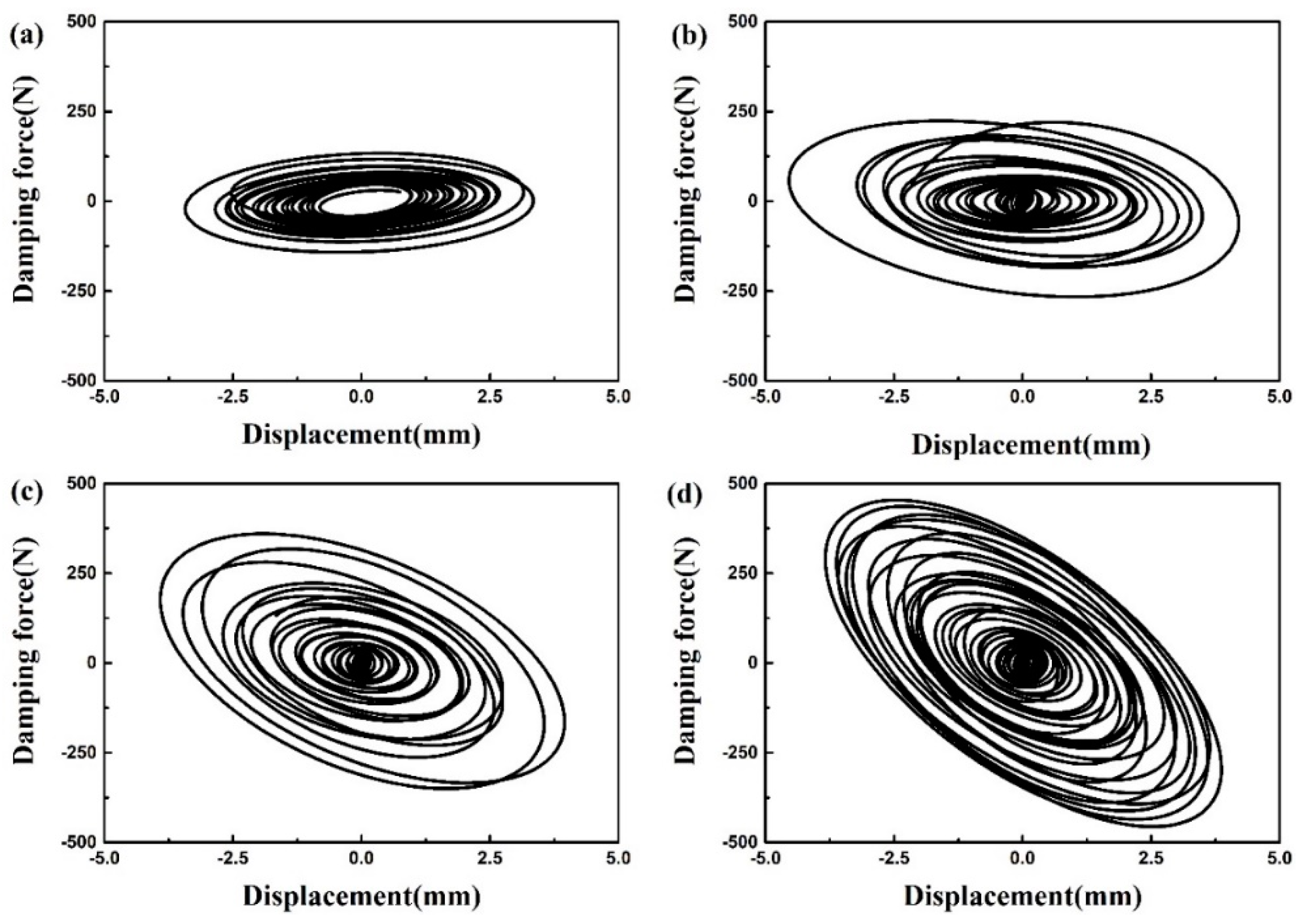
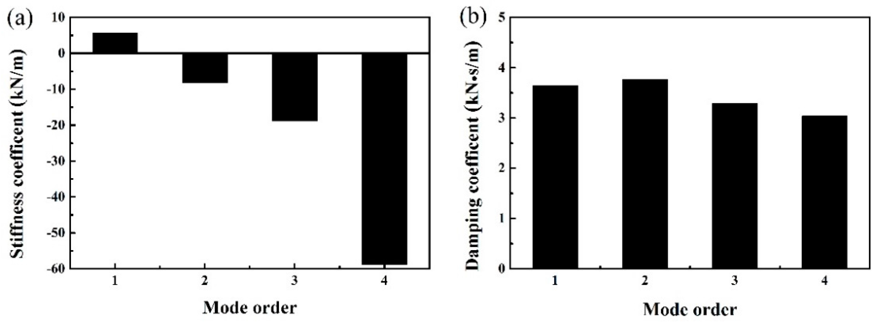
The hysteretic loops of the self-powered MR damper are shown in Figure 15. The damping characteristics of the self-powered MR damper are quite similar to a combination of a traditional linear viscous damper and a negative stiffness device in the higher mode. Accordingly, the equivalent damping and stiffness coefficients are identified and shown in Figure 16. The equivalent damping coefficients are almost the same for the first four modes, while the stiffness coefficient jumps from positive to negative values after the second mode. Moreover, the negative stiffness coefficient increases with an increase in the mode order of the cable. Hence, the self-powered MR damper is found to be similar to the generator with respect to the negative stiffness characteristics.
Unlike the self-powered MR damper system in this paper, other mentioned self-powered MR dampers, where the MR damper and the generator are at the same location, have not exhibited negative stiffness behavior [27]. The results imply that the negative stiffness may be attributed to the relative positions of the rotary DC generator and the damper in a self-powered MR damper system. Hence, the proposed self-powered MR damper system, where the generator and the MR damper are separated, seems to be more promising than the conventional, compact self-powered MR damper. However, the effects of the relative positions of the rotary DC generator and the damper on the induced negative stiffness of the self-powered MR damper and control performance of the cable still require further investigation.
4.4. Effect of Negative Stiffness of the Damper on the Performance of the Cable
Negative stiffness characteristics of semi-active/active control systems have been found and investigated in the area of structural vibration control [39,40,41,42]. The role of negative stiffness in the semi-active control of magnetorheological dampers has been well demonstrated by Høgsberg [43]. According to the research results above, it has been confirmed that the negative stiffness is capable of improving the energy dissipation ability of a conventional damper. In view of such benefits, several passive negative stiffness dampers were also proposed to enhance the vibration control performance of the cable, such as a viscous damper with a negative magnetic stiffness spring [44], an oil damper with two pre-compressed springs [45], and a viscous inertial mass damper [46].
When a negative stiffness viscous damper is quite close to the cable end, the supplemental modal damping ratio of the stay cable can be expressed as [36,40]
where and η respectively denote the dimensionless negative stiffness and the dimensionless damping coefficient, which are given by
where a, k, and c represent the location, the negative stiffness, and the damping coefficient of the damper, respectively; T, m, l, and i denote the tension force, the mass per unit length, the length, and the mode order of the cable, respectively.
When the optimum damping coefficient is determined by
the maximum modal damping ratio of the cable can be obtained as
Equation (12) clearly indicates that the incorporation of negative stiffness into a linear viscous damper can enhance the maximum modal damping ratio of the cable. For the new self-powered MR damper system in this paper, the test results shown in Section 4.2 and Section 4.3 have demonstrated that both the self-powered MR damper and the generator are able to exhibit negative stiffness behavior for the higher-order mode of the cable. Additionally, the negative stiffness increases as the mode order of the test cable increases. In summary, the proposed self-powered MR damper control system shows superiority over traditional passive MR dampers or viscous dampers.
5. Conclusions
To eliminate the power supply problem of a traditional MR damper, a new self-powered MR damper control system was developed based on electromagnetic energy harvesting technology. Unlike other self-powered MR dampers, the MR damper and therotary DC generator are not at the same location on the stay cable in this paper. The feasibility and effectiveness of the new system for suppressing cable vibration was experimentally evaluated via a 21.6 m inclined cable model. The test results indicate that the developed self-powered MR damper system can provide more cable damping than a passively operated MR damper with constant voltage. The increased supplemental modal damping ratios of the cable in the first four modes are mainly attributed to two factors. One is that the self-powered MR damper can exhibit negative stiffness behavior for the case of the higher-order mode of the cable, which is capable of enhancing the control performance; the other is that the rotary DC generator in the self-powered MR damper system also provides supplemental damping to the cable.
Since the main purpose of this paper is merely to demonstrate the feasibility of the self-powered MR damper system in reducing cable vibration, the system may not show the best possible performance in the test. Hence, the optimum design of the system should be considered in later research, including the relative locations of the generator and the MR damper, the sizes and parameters of both the rotary DC generator and the MR damper, and the effective transmission radius of the sprocket.
Acknowledgments
The authors gratefully acknowledge the financial support from the National Natural Science Foundation of China (Grant No. 51308214 and 51578151) and the National Basic Research Program of China (973 Program) (Grant No. 2015CB057702 and 2015CB060000).
Author Contributions
Zhihao Wang and Zhengqing Chen conceived the idea and designed the experiments; Zhihao Wang performed the experiment and analyzed the data; Zhihao Wang and Hui Gao wrote the paper; Zhengqing Chen and Hao Wang reviewed and revised the paper.
Conflicts of Interest
The authors declare no conflict of interest.
References
- Krenk, S. Vibration of a taut cable with an external damper. J. Appl. Mech. 2000, 67, 772–776. [Google Scholar] [CrossRef]
- Johnson, E.A.; Christenson, R.E.; Spencer, B.F. Semi-active damping of cables with sag. Comput.-Aided Civ. Infrastruct. Eng. 2003, 18, 132–146. [Google Scholar] [CrossRef]
- Spencer, B.F.; Dyke, S.J.; Sain, M.K.; Carlson, J.D. Phenomenological model of a magnetorheological damper. J. Eng. Mech. 1997, 123, 230–238. [Google Scholar] [CrossRef]
- Duan, Y.F.; Ni, Y.Q.; Ko, J.M. Cable vibration control using magneto-rheological (MR) dampers. J. Intell. Mater. Syst. Struct. 2006, 17, 321–325. [Google Scholar] [CrossRef]
- Christenson, R.E.; Spencer, B.F.; Johnson, E.A. Experimental verification of smart cable damping. J. Eng. Mech. 2006, 132, 268–278. [Google Scholar] [CrossRef]
- Liu, M.; Song, G.B.; Li, H. Non-model-based semi-active vibration suppression of stay cables using magneto-rheological fluid damper. Smart Mater. Struct. 2007, 16, 1447–1452. [Google Scholar] [CrossRef]
- Cai, C.S.; Wu, W.J.; Araujo, M. Cable vibration control with a TMD-MR damper system: Experimental exploration. J. Struct. Eng. 2007, 133, 629–637. [Google Scholar] [CrossRef]
- Huang, H.W.; Sun, L.M.; Jiang, X.L. Vibration mitigation of stay cable using optimally tuned MR damper. Smart Struct. Syst. 2012, 9, 35–53. [Google Scholar] [CrossRef]
- Chang, C.M.; Wang, Z.H.; Spencer, B.F.; Chen, Z.Q. Semi-active damped outriggers for seismic protection of high-rise buildings. Smart Struct. Syst. 2013, 11, 435–451. [Google Scholar] [CrossRef]
- Fu, W.Q.; Zhang, C.W.; Sun, L.; Askari, M.; Samali, B.; Chung, K.L.; Sharafi, P. Experimental investigation of a base isolation system incorporating MR dampers with the high-order single step control algorithm. Appl. Sci. 2017, 7, 344. [Google Scholar] [CrossRef]
- Chen, Z.Q.; Wang, X.Y.; Ko, J.M.; Ni, Y.Q.; Spencer, B.F.; Yang, G.; Hu, J.H. MR damping system for mitigating wind-rain induced vibration on Dongting Lake Cable-Stayed Bridge. Wind Struct. 2004, 7, 293–304. [Google Scholar] [CrossRef]
- Li, H.; Liu, M.; Li, J.H.; Guan, X.C.; Ou, J.P. Vibration control of stay cables of Shandong Binzhou Yellow River Highway Bridge by using magnetorheological fluid dampers. J. Bridge Eng. 2007, 12, 401–409. [Google Scholar] [CrossRef]
- Weber, F.; Distl, H. Amplitude and frequency independent cable damping of Sutong Bridge and Russky Bridge by magnetorheological dampers. Struct. Control Health Monit. 2014, 22, 237–254. [Google Scholar] [CrossRef]
- Scruggs, J.T.; Iwan, W.D. Control of a civil structure using an electric machine with semi-active capability. J. Struct. Eng. 2003, 129, 951–959. [Google Scholar] [CrossRef]
- Wang, Z.H.; Chen, Z.Q.; Spencer, B.F. Self-powered and sensing control system based on MR damper, presentation and application. In Proceedings of the SPIE on Sensors and Smart Structures Technologies for Civil, Mechanical, and Aerospace Systems, San Diego, CA, USA, 8–13 March 2009. [Google Scholar]
- Cho, S.W.; Jung, H.J.; Lee, I.W. Smart passive system based on magnetorheological damper. Smart Mater. Struct. 2005, 14, 707–714. [Google Scholar] [CrossRef]
- Cassidy, I.L.; Scruggs, J.T.; Behrens, S.; Gavin, H.P. Design and experimental characterization of an electromagnetic transducer for large-scale vibratory energy harvesting applications. J. Intell. Mater. Syst. Struct. 2011, 22, 2009–2024. [Google Scholar] [CrossRef]
- Shen, W.A.; Zhu, S.Y.; Zhu, H.P. Experimental study on using electromagnetic devices on bridge stay cables for simultaneous energy harvesting and vibration damping. Smart Mater. Struct. 2016, 25, 065011. [Google Scholar] [CrossRef]
- Chin, W.K.; Ong, Z.C.; Kong, K.K.; Khoo, S.Y.; Huang, Y.H.; Chong, W.T. Enhancement of energy harvesting performance by a coupled bluff splitter body and PVEH plate through vortex induced vibration near resonance. Appl. Sci. 2017, 7, 921. [Google Scholar] [CrossRef]
- Mitcheson, P.D.; Miao, P.; Stark, B.H.; Yeatman, E.M.; Holmes, A.S.; Green, T.C. MEMS electrostatic micropower generator for low frequency operation. Sens. Actuators A-Phys. 2004, 115, 523–529. [Google Scholar] [CrossRef] [Green Version]
- Kang, G.; Kim, K.S.; Kim, S. Note: Analysis of the efficiency of a dielectric elastomer generator for energy harvesting. Rev. Sci. Instrum. 2011, 82, 046101. [Google Scholar] [CrossRef] [PubMed]
- Choi, K.M.; Jung, H.J.; Lee, H.J.; Cho, H.W. Feasibility study of an MR damper-based smart passive control system employing an electromagnetic induction device. Smart Mater. Struct. 2007, 16, 2323–2329. [Google Scholar] [CrossRef]
- Choi, Y.T.; Wereley, N.M. Self-powered magnetorheological dampers. J. Vib. Acoust. 2009, 131, 044501. [Google Scholar] [CrossRef]
- Kim, I.H.; Jung, H.J.; Koo, J.H. Experimental evaluation of a self-powered smart damping system in reducing vibration of a full-scale stay cable. Smart Mater. Struct. 2010, 19, 115027. [Google Scholar] [CrossRef]
- Sapiński, B. Energy-harvesting linear MR damper: Prototyping and testing. Smart Mater. Struct. 2014, 23, 035021. [Google Scholar] [CrossRef]
- Gupta, A.; Jendrzejczyk, J.A.; Mulcahy, T.M.; Hull, J.R. Design of electromagnetic shock absorbers. Int. J. Mech. Mater. Des. 2006, 3, 285–291. [Google Scholar] [CrossRef]
- Guan, X.C.; Huang, Y.H.; Ru, Y.; Li, H.; Ou, J.P. A novel self-powered MR damper: Theoretical and experimental analysis. Smart Mater. Struct. 2015, 24, 105033. [Google Scholar]
- Sapiński, B. Experimental investigation of an energy harvesting rotary generator-MR damper System. J. Theor. Appl. Mech-Pol. 2016, 54, 679–690. [Google Scholar] [CrossRef]
- Caracoglia, L.; Jones, N.P. Damping of taut-cable Systems: Two dampers on a single stay. J. Eng. Mech. 2007, 133, 1050–1060. [Google Scholar] [CrossRef]
- Cu, V.H.; Han, B.; Wang, F. Damping of a taut cable with two attached high damping rubber dampers. Struct. Eng. Mech. 2015, 55, 1261–1278. [Google Scholar] [CrossRef]
- Shen, W.A.; Zhu, S.Y. Harvesting energy via electromagnetic damper: Application to bridge stay cables. J. Intell. Mater. Syst. Struct. 2015, 26, 3–19. [Google Scholar] [CrossRef]
- Jung, H.J.; Jang, D.D.; Koo, J.H.; Cho, S.W. Experimental evaluation of a ‘self-sensing’ capability of an electromagnetic induction system designed for MR dampers. J. Intell. Mater. Syst. Struct. 2010, 21, 827–835. [Google Scholar] [CrossRef]
- Occhiuzzi, A.; Spizzuoco, M.; Serino, G. Experimental analysis of magnetorheological dampers for structural control. Smart Mater. Struct. 2003, 12, 703–711. [Google Scholar] [CrossRef]
- Weber, F.; Høgsberg, J.; Krenk, S. Optimal tuning of amplitude proportional coulomb friction damper for maximum cable damping. J. Struct. Eng. 2010, 136, 123–134. [Google Scholar] [CrossRef]
- Ikago, K.; Saito, K.; Inoue, N. Seismic control of single-degree-of-freedom structure using tuned viscous mass damper. Earthq. Eng. Struct. Dyn. 2012, 41, 453–474. [Google Scholar] [CrossRef]
- Chen, L.; Sun, L.M.; Nagarajaiah, S. Cable with discrete negative stiffness device and viscous damper: Passive realization and general characteristics. Smart Struct. Syst. 2015, 15, 627–643. [Google Scholar] [CrossRef]
- Weber, F.; Distl, H. Semi-active damping with negative stiffness for multi-mode cable vibration mitigation: Approximate collocated control solution. Smart Mater. Struct. 2015, 24, 115015. [Google Scholar] [CrossRef]
- Xu, Y.L.; Yu, Z. Vibration of inclined sag cables with oil dampers in cable-stayed bridges. J. Bridge Eng. 1998, 3, 194–203. [Google Scholar] [CrossRef]
- Iemura, H.; Pradono, M.H. Application of pseudo negative stiffness control to the benchmark cable-stayed bridges. J. Struct. Control 2003, 10, 187–203. [Google Scholar] [CrossRef]
- Li, H.; Liu, M.; Ou, J.P. Negative stiffness characteristics of active and semi-active control systems for stay cables. Struct. Control Health Monit. 2008, 15, 120–142. [Google Scholar] [CrossRef]
- Pradono, M.H.; Iemura, H.; Igarashi, A.; Toyooka, A.; Kalantari, A. Passively controlled MR damper in the benchmark structural control problem for seismically excited highway bridge. Struct. Control Health Monit. 2009, 16, 626–638. [Google Scholar] [CrossRef]
- Weber, F.; Boston, C. Clipped viscous damping with negative stiffness for semi-active cable damping. Smart Mater. Struct. 2011, 20, 045007. [Google Scholar] [CrossRef]
- Høgsberg, J. The role of negative stiffness in semi-active control of magneto-rheological dampers. Struct. Control Health Monit. 2011, 18, 289–304. [Google Scholar] [CrossRef]
- Shi, X.; Zhu, S.Y.; Li, J.Y.; Spencer, B.F. Dynamic behavior of stay cables with passive negative stiffness dampers. Smart Mater. Struct. 2016, 25, 075044. [Google Scholar] [CrossRef]
- Zhou, P.; Li, H. Modeling and control performance of a negative stiffness damper for suppressing stay cable vibrations. Struct. Control Health Monit. 2016, 23, 764–782. [Google Scholar] [CrossRef]
- Lu, L.; Duan, Y.F.; Spencer, B.F.; Lu, X.L.; Zhou, Y. Inertial mass damper for mitigating cable vibration. Struct. Control Health Monit. 2017, 24, e1986. [Google Scholar] [CrossRef]
Figure 1.
Schematic diagram of the self-powered MR damper system for cable vibration control.

Figure 2.
The equivalent circuit model for a rotary DC generator.
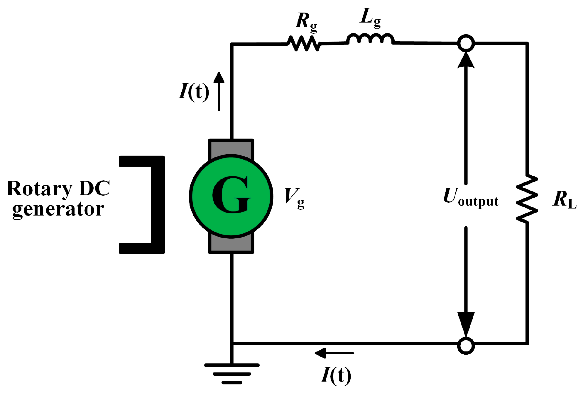
Figure 3.
Experimental setup for identifying the back electromotive force constant of the generator. (a) The rotary DC generator; (b) Experimental setup.
Figure 3.
Experimental setup for identifying the back electromotive force constant of the generator. (a) The rotary DC generator; (b) Experimental setup.

Figure 4.
The relationship between the back electromotive force and the rotational speed of the generator.
Figure 4.
The relationship between the back electromotive force and the rotational speed of the generator.
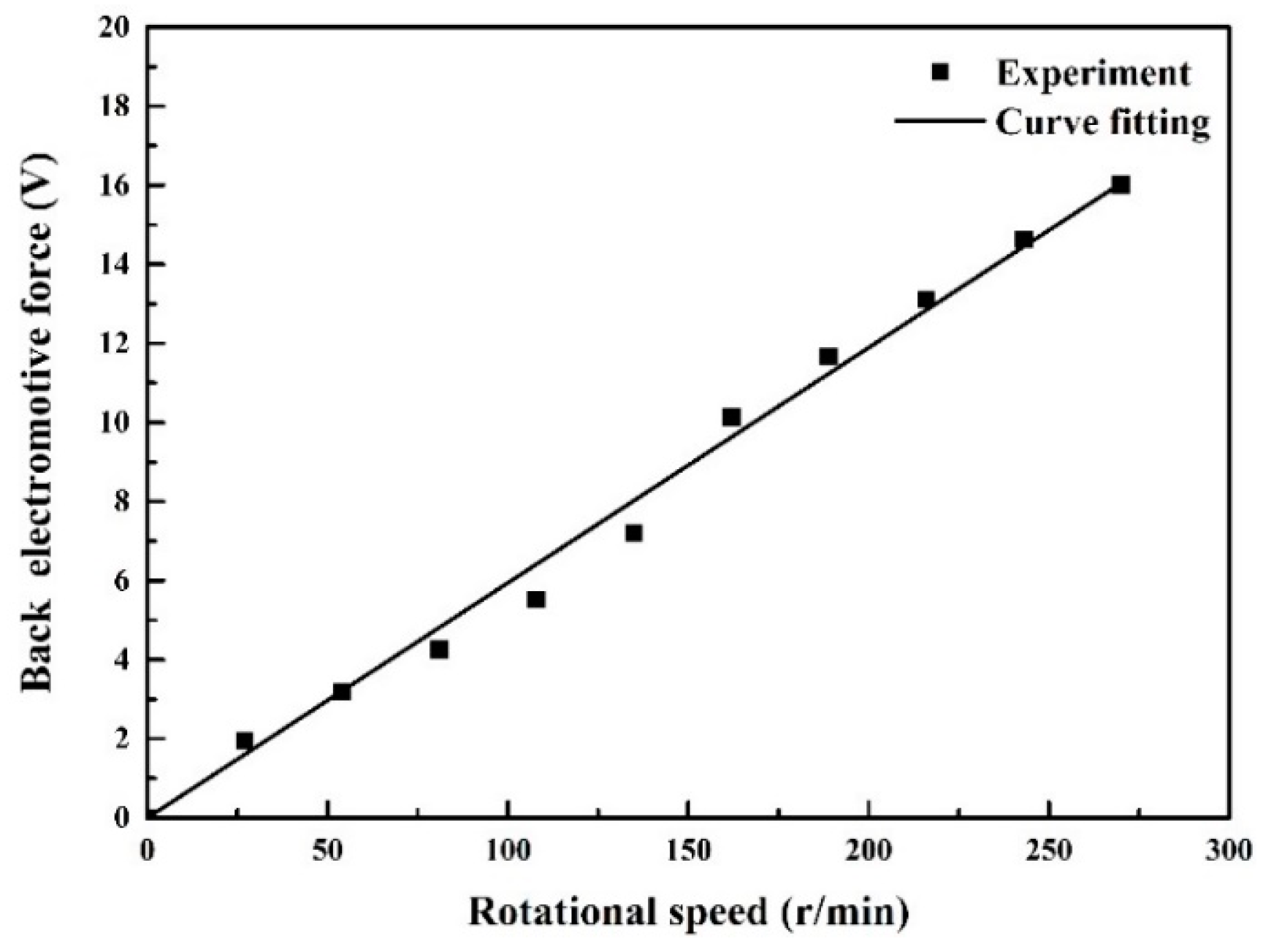
Figure 5.
Experimental setup for the energy harvesting capability of the generator.

Figure 6.
The output voltage and output power of the generator versus the excitation frequency (RL = 15 Ω). (a) The output voltage versus the excitation frequency; (b) The harvested electrical energy versus the excitation frequency.
Figure 6.
The output voltage and output power of the generator versus the excitation frequency (RL = 15 Ω). (a) The output voltage versus the excitation frequency; (b) The harvested electrical energy versus the excitation frequency.

Figure 7.
General layout of the experimental setup for cable vibration control.
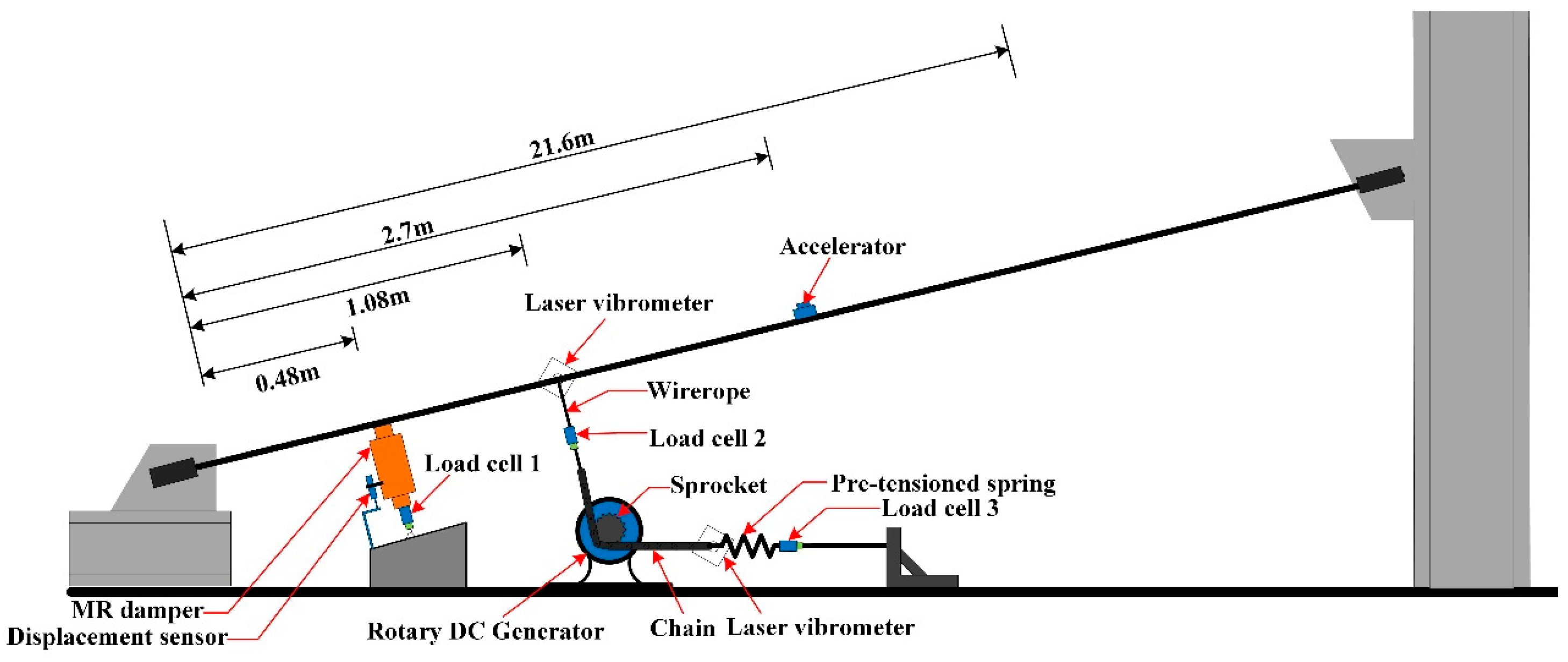
Figure 8.
Experimental setup photos for cable vibration control. (a) Stay cable; (b) Self-powered MR damper installed on the cable.
Figure 8.
Experimental setup photos for cable vibration control. (a) Stay cable; (b) Self-powered MR damper installed on the cable.
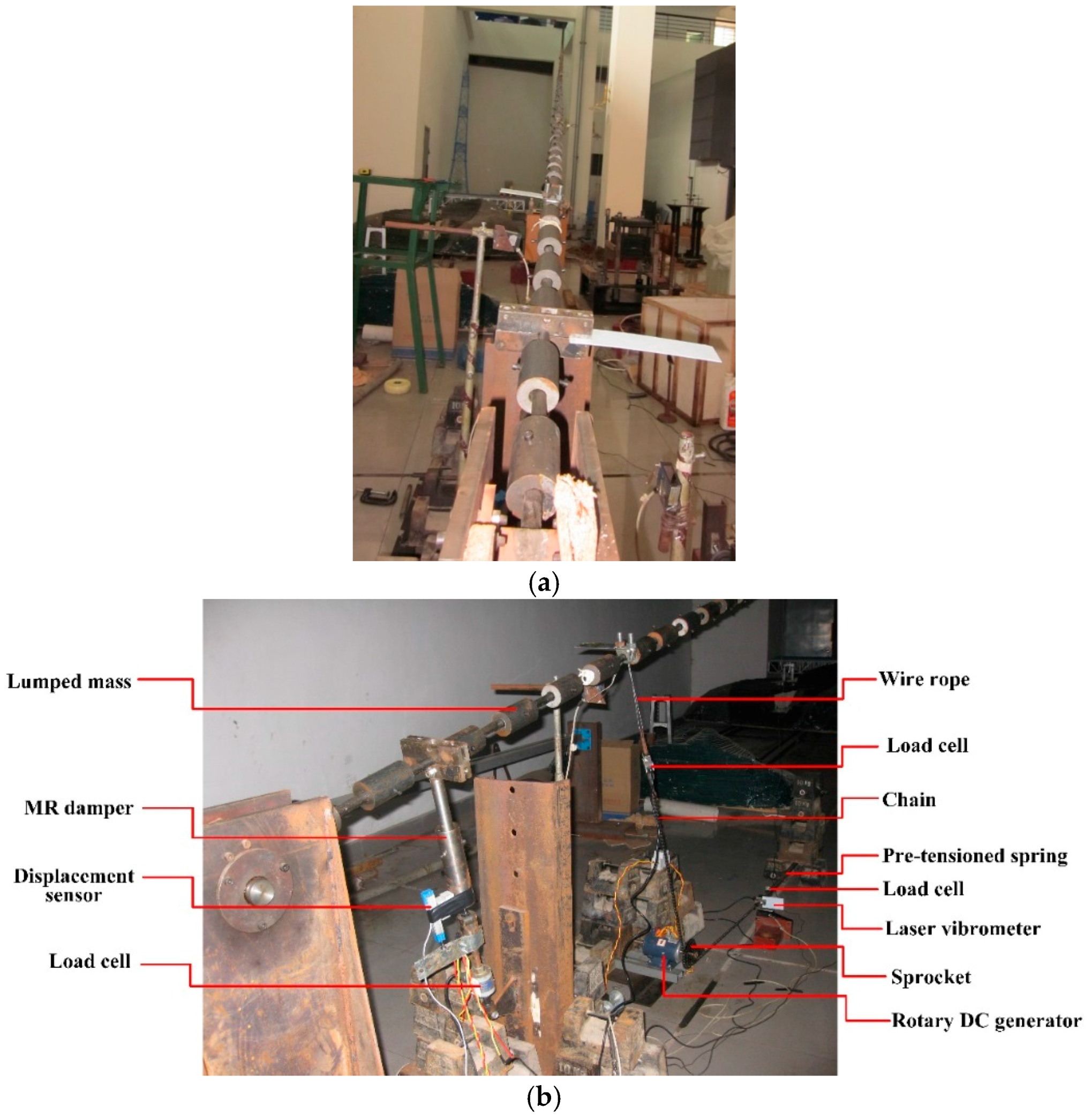
Figure 9.
Damping ratios in the first four modes of the cable versus constant voltage of the MR damper.
Figure 9.
Damping ratios in the first four modes of the cable versus constant voltage of the MR damper.

Figure 10.
Second mode acceleration time histories of the cable controlled by a passive MR damper with different constant voltages: (a) 0 V; (b) 0.5 V; and (c) 1 V.
Figure 10.
Second mode acceleration time histories of the cable controlled by a passive MR damper with different constant voltages: (a) 0 V; (b) 0.5 V; and (c) 1 V.

Figure 11.
The damping force versus the linear displacement of the DC generator. (a) First mode; (b) Second mode; (c) Third mode; and (d) Fourth mode.
Figure 11.
The damping force versus the linear displacement of the DC generator. (a) First mode; (b) Second mode; (c) Third mode; and (d) Fourth mode.

Figure 12.
Identified damping coefficients and stiffness coefficients of the DC generator: (a) Identified damping coefficients; (b) Identified stiffness coefficients.
Figure 12.
Identified damping coefficients and stiffness coefficients of the DC generator: (a) Identified damping coefficients; (b) Identified stiffness coefficients.

Figure 13.
Time histories of acceleration, input voltage, and damping force for the first mode of the cable.
Figure 13.
Time histories of acceleration, input voltage, and damping force for the first mode of the cable.

Figure 14.
Time histories of acceleration, input voltage, and damping force for the fourth mode of the cable.
Figure 14.
Time histories of acceleration, input voltage, and damping force for the fourth mode of the cable.

Figure 15.
Hysteretic loops of the self-powered MR damper for different modes of the cable. (a) First mode; (b) Second mode; (c) Third mode; and (d) Fourth mode.
Figure 15.
Hysteretic loops of the self-powered MR damper for different modes of the cable. (a) First mode; (b) Second mode; (c) Third mode; and (d) Fourth mode.

Figure 16.
Identified damping coefficients and stiffness coefficients of the self-powered MR damper. (a) Identified stiffness coefficients; (b) Identified damping coefficients.
Figure 16.
Identified damping coefficients and stiffness coefficients of the self-powered MR damper. (a) Identified stiffness coefficients; (b) Identified damping coefficients.


Table 1.
Properties of the model cable.
| Parameter | Value |
|---|---|
| Cable length (l) | 21.6 m |
| Cable cross section area (A) | 1.374 cm2 |
| Mass per unit length (m) | 11.01 kg/m |
| Elastic modulus (E) | 200 GPa |
| Static tension (T) | 20.5 kN |
| Inclination angle (θ) | 14.2° |
| Sag parameter (λ2) | 16.28 |
Table 2.
Natural frequencies and modal damping ratios in the first four modes of an uncontrolled cable.
Table 2.
Natural frequencies and modal damping ratios in the first four modes of an uncontrolled cable.
| Mode Order | Natural Frequency (Hz) | Modal Damping Ratio (%) |
|---|---|---|
| 1 | 1.434 | 0.59 |
| 2 | 1.969 | 0.15 |
| 3 | 2.983 | 0.11 |
| 4 | 3.912 | 0.12 |
Table 3.
Modal damping ratios of the cable in the first four modes with electromagnetic damping alone.
Table 3.
Modal damping ratios of the cable in the first four modes with electromagnetic damping alone.
| Mode Order | Short Circuit | Circuit Loaded with an MR Damper | ||
|---|---|---|---|---|
| Damping Ratio (%) | Supplemental Damping Ratio (%) | Damping Ratio (%) | Supplemental Damping Ratio (%) | |
| 1 | 0.71 | 0.12 | 0.68 | 0.09 |
| 2 | 0.59 | 0.44 | 0.54 | 0.39 |
| 3 | 0.81 | 0.70 | 0.65 | 0.54 |
| 4 | 1.05 | 0.93 | 0.74 | 0.62 |
Table 4.
Comparisons of modal damping ratios of the cable with different control devices.
| Mode Order | Damping Ratio (%) | |||
|---|---|---|---|---|
| Uncontrolled | MR Damper in Passive Mode | Electromagnetic Damping Alone (Load MR Damper) | Self-Powered MR Damper System | |
| 1 | 0.59 | 1.16 | 0.68 | 0.87 |
| 2 | 0.15 | 1.10 | 0.54 | 1.45 |
| 3 | 0.11 | 1.23 | 0.65 | 1.69 |
| 4 | 0.12 | 1.07 | 0.74 | 1.53 |
© 2018 by the authors. Licensee MDPI, Basel, Switzerland. This article is an open access article distributed under the terms and conditions of the Creative Commons Attribution (CC BY) license (http://creativecommons.org/licenses/by/4.0/).
Share and Cite
MDPI and ACS Style
Wang, Z.; Chen, Z.; Gao, H.; Wang, H. Development of a Self-Powered Magnetorheological Damper System for Cable Vibration Control. Appl. Sci. 2018, 8, 118. https://doi.org/10.3390/app8010118
AMA Style
Wang Z, Chen Z, Gao H, Wang H. Development of a Self-Powered Magnetorheological Damper System for Cable Vibration Control. Applied Sciences. 2018; 8(1):118. https://doi.org/10.3390/app8010118
Chicago/Turabian StyleWang, Zhihao, Zhengqing Chen, Hui Gao, and Hao Wang. 2018. "Development of a Self-Powered Magnetorheological Damper System for Cable Vibration Control" Applied Sciences 8, no. 1: 118. https://doi.org/10.3390/app8010118
Note that from the first issue of 2016, this journal uses article numbers instead of page numbers. See further details here.