1. Introduction
To alleviate the current energy crisis and environmental pollution, sustainable, and eco-friendly energy conversion and storage systems are urgently needed. Rechargeable lithium-ion batteries have been attracting great attention as power sources for various applications including modern electronic devices, hybrid vehicles, and various electrical power systems [
1]. Among them, lithium–sulfur (Li–S) batteries are considered as the most promising candidates for the next generation of high-energy storage devices due to their high theoretical specific capacity (1675 mAh/g) and energy density (2500 Wh/kg), which is far more than those of the commercially available Li–graphite batteries [
2,
3,
4,
5,
6]. Moreover, benefitting from the goodness of sulfur substance, Li–S batteries possess the merits of the natural abundance, low cost, and environmental friendliness, which enable them more competitive against their counterparts [
7].
However, large-scale commercialization of Li–S batteries is still hampered by several issues. Among them, the so-called ‘shuttle effect’ resulting from the dissolution of lithium polysulfide intermediates (Li
2S
x, 4 ≤
x ≤ 8) into the liquid electrolyte acts as the major obstacle. Specifically, the soluble polysulfides could diffuse through the separator and directly react with the lithium negative electrode during the discharge process; this would bring in passivation and loss of the active material, which consequently gives rise to a rapidly fading capacity and low coulombic efficiency. Besides the volume change aroused by density difference between sulfur and polysulfides, the intrinsic poor electronic and ionic conductivity of sulfur and its discharging products (Li
2S and Li
2S
2) also hinder the electrochemical performance of Li–S battery [
8,
9,
10,
11,
12].
In recent years, extensive efforts have been devoted to solving these problems. Hua et al. introduced a kind of polysulfide-scission reagents to favor the formation of insoluble Li
2S and/or Li
2S
2 instead of the soluble Li
2S
x (4 ≤
x ≤ 8) during the charge/discharge process. By this strategy, the shuttle effect could be effectively suppressed and an improved electrochemical performance was achieved in the Li–S batteries [
13]. Xiao et al. applied a lightweight TiO
2/graphene interlayer as a polysulfide absorbent for Li–S batteries to suppress the shuttling of polysulfides [
14]. Li et al. introduced an ordered meso-microporous core–shell carbon (MMCS) as a sulfur container, which combines the advantages of both mesoporous and microporous carbon. With large pore volume and highly ordered porous structure of carbon host, the problem of volume change and low electron transfer rate could be overcome [
15]. Fu et al. proposed a sulfur–polymer composite consisting of polymer acid doped polypyrrole mixed ionic−electronic conductor to improve the ion and electron transport [
16]. In spite of plentiful investigations, binder is heavily overlooked by most researchers. As a matter of fact, binder is one of the most important compositions in the cathode. An eligible binder should meet several requirements including enough adhesion stress to hold the electrical contact of active material with current collector, and structure maintaining ability during the charge and discharge process without hindering the transport of electron and lithium ion. To date, only a few studies have involved the binders. Lacey et al. proposed a binder composed of poly (ethylene oxide) (PEO) and poly(vinylpyrrolidone) (PVP), which combines the local improvement to solvent system offered by PEO and the stabilizing effect of PVP on polysulfides [
17]. Zhang adopted a cationic polyelectrolyte binder for high sulfur loading cathodes, whose function is to retain the void structure generated by the dissolution of polysulfides and thus benefit a longer cycle life for the battery [
18]. However, most of them failed to improve cycling performance from the comprehensive perspective of chemical reaction and structure.
Herein, Thiokol, a type of polysulfide rubber, was introduced as a novel binder into the sulfur cathode. Polysulfide rubber is a kind of synthetic rubber polycondensationed by alkyl dihalide and alkali metal or alkaline earth metal polysulfide. The mechanism of catalysts slicing disulfide bonds was proposed. It was believed that the disulfide bonds in lithium polysulfides could be sliced by thiols of the Thiokol, thus reducing the amount of long-chain soluble polysulfides, which was to blame for the shuttle effect during the cycling. Besides, it will not dissolve in electrolyte during charge and discharge, which could help to stabilize the cathode structure and contribute to the long cycle life of the battery [
8,
18].
2. Materials and Methods
2.1. Materials
Sublimed sulfur (99.5%, chemical grade, Shanghai Hushi Corp. Ltd., Shanghai, China) and acetylene black (Lizhiyuan Corp. Ltd., Shenzhen, China) were used as the active material and conductive additive in the cathode, respectively. Polysulfide rubber (Thiokol, HS(C
2H
4OCH
2OC
2H
4SS)
nC
2H
4OCH
2OC
2H
4SH, LP-33, Toray Industries, Inc., Tokyo, Japan) and polyvinylidene fluoride (PVDF, Shanghai 3F New Materials Co., Shanghai, China) were separately employed as binders for the sulfur cathode.
N-methyl-2-pyrrolidone (NMP) was purchased from Sinopharm Chemical Reagent, Corp., Shanghai, China. Polysulfide Li
2S
6 was synthesized in the lab according to the previous method [
19].
2.2. Cathode Preparation
Two types of sulfur cathodes were prepared separately using Thiokol and PVDF as the binder. In both cases, sulfur, acetylene black, and binder were mixed at a weight ratio of 3:2:1. The mixture was added into the NMP solvent and subjected to ball milling for 12 h. After that, the mixed slurries were coated onto Al foils with a doctor blade and were subsequently dried under vacuum at 60 °C for 24 h. Finally, the cathodes were fabricated by cutting the as-prepared coated Al foils into small rounds with a diameter of 14 mm.
2.3. Characterization
CR2032 coin-type cells with lithium metal as the anode were assembled in an argon-filled glove box to test the electrochemical performance. A Celgard 2300 polypropylene membrane was used as the separator. The electrolyte was a mixture of 1 M lithium bis(trifluoromethanesulfonyl)imide (LiTFSI, Beijing Chemical Reagent Research Institute, Beijing, China) and 0.4 M LiNO3 dissolved in 1,3-dioxolane (DOL) and 1,2-dimethoxy ethane (DME) (1:1, v:v, Aladdin Reagent Corp., Shanghai, China). Cyclic voltammetry curves (CV) were recorded on an electrochemical workstation (CHI 660E, CH Instruments, Shanghai, China) at a scanning rate of 0.1 mV/s from 1.5 to 3 V. Electrochemical impedance spectroscopy (EIS) measurements were also performed on CHI 660E from 0.01 Hz to 100 kHz with an AC voltage amplitude of 5 mV. The charge–discharge performance of the batteries was tested galvanostatically at room temperature in the voltage window of 1.7–2.8 V using a LAND CT2001A instrument (Wuhan LAND electronics, Wuhan, China). The morphologies of the sulfur cathode were observed with a field emission scanning electron microscope (SEM, HITACHI S-4700, Hitachi High Technologies America, New York, NY, USA). UV–visible (UV–vis) spectra were obtained by a UV–vis spectrophotometer (Shimadzu UV-2550, Shimadzu, Kyoto, Japan). X-ray diffraction (XRD) patterns were acquired with a rotation anode high power X-ray diffractometer (RU-200B/D/MAX-RB, Rigaku, Tokyo, Japan).
3. Results and Discussion
The CV curves of the Li–S battery with the Thiokol and PVDF binder at a scan rate of 0.1 mV/s are shown in
Figure 1a,b, respectively. Both curves show three distinct peaks at similar positions including two reduction peaks and one oxidation peak. One slight oxidation shoulder appears near the main oxidation peak for the battery with the Thiokol binder. According to the previous studies, the reduction peak around 2.3 V could be assigned to the transition of element sulfur to the long-chain polysulfides (Li
2S
x, 4 ≤
x ≤ 8), while the reduction peak around 2.0 V be attributed to the further conversion into the short-chain polysulfides such as Li
2S
2 and/or Li
2S [
20,
21,
22,
23]. Conversely, the main oxidation peak in the lower potential represents the conversion of Li
2S and/or Li
2S
2 to long-chain polysulfides and the shoulder at higher potential represents the further oxidation to elemental sulfur [
24]. In addition, a small reduction peak between 1.7 and 1.5 V can be seen if carefully checked, which might originate from the lithiation of Thiokol. Comparison of the three cycles shows that the cyclic voltammograms almost coincided with each other, indicating a high electrochemical reversibility of the battery with the Thiokol binder.
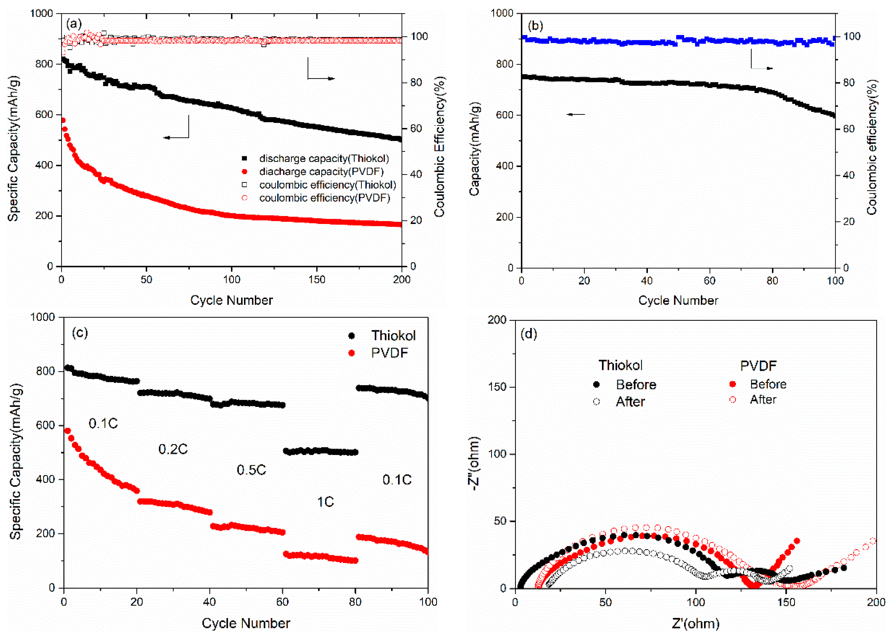
Figure 2a compares the discharge capacity of the Li–S batteries with the binders of Thiokol and PVDF, respectively. It could be seen from
Figure 2a that the battery with the Thiokol binder delivered an initial discharge capacity of 819 mAh/g at 0.1 C while the battery with PVDF binder only delivered an initial value of 578 mAh/g. In addition, the discharge capacity of the Thiokol binder remained 501 mAh/g after 200 cycles, indicating a capacity retention rate of 61.1%; while the discharge capacity of the PVDF binder dropped to 166 mAh/g, with a capacity retention rate of only 28.7%. That is to say, compared to the battery with conventional PVDF binder, the initial discharge capacity for the battery with the Thiokol binder were increased by 42%—that is from 578 to 819 mAh/g—while the capacity after 200 cycles were increased by 201%—which is from 166 to 501 mAh/g. This suggested that the Thiokol binder improved not only the initial discharge capacity but also the capacity retention rate, compared to PVDF. Besides, the coulombic efficiency of the two kinds of batteries remain at a high level, indicating high utilization of active materials.
The cycling performance of the battery with the Thiokol binder at 0.5 C is shown in
Figure 2b. With an initial discharge capacity of 751 mAh/g, the capacity slowly dropped to 597 mAh/g after 100 cycles, indicating a capacity retention of 79.5%. The coulombic efficiency also kept as high as 96.4%. The result is encouraging since it suggested the Thiokol binder in this work could maintain the structural stability of the sulfur cathode during the long charge–discharge cycles. That is to say, it would not collapse, even as the charge and discharge occurs rapidly due to the increase of current density, consequently leading to a long cycle life of the Li–S battery at high current density.
Figure 2c presents the rate performance of the Li–S batteries with the Thiokol and PVDF binder. With an initial value of 813 mAh/g at 0.1 C, the capacity of Li–S batteries with the Thiokol binder remained around 720, 680, and 505 mAh/g at 0.2, 0.5, and 1 C in 20 cycles, respectively, and returned back to 739 mAh/g when the rate was 0.1 C. While for the battery with PVDF binder, the cell only reserved 52.2% of the capacity when the rate went back to 0.1 C after a continuous cycling of 0.1, 0.2, and 0.5 C. In contrast, the excellent reversibility of the capacity as high as 90.9% supported strongly again that the Li–S battery with Thiokol binder was highly stable and reversible.
Electrochemical impedance spectra (EIS) of the battery with the Thiokol and PVDF binder before and after circles are shown in
Figure 2d in the frequency range from 0.01 Hz to 100 kHz. The Nyquist plots of the battery with Thiokol binder consist of two semicircles, which correspond to the charge-transfer resistance (R
ct) occurring at the electrolyte–electrode interface in the medium-to-low frequency region and the resistance (R
t) from a passivation film in the high frequency region, respectively. While the Nyquist plots of the battery with PVDF binder only involve one semicircle that corresponds to R
ct. The intersection between the initial part of the Nyquist plot and the real axis represents the electrolyte resistance (R
e). A few increase of R
e for the battery with Thiokol binder was observed after 50 cycles, which might reveal that most of the polysulfides still remain in the cathode. This could also reflect the restriction of Thiokol on the shuttle effect. Besides, compared to the battery before cycling, there is no obvious increase of R
ct for the battery with Thiokol binder, which indicates that the Thiokol binder enables the conductive contacts between active materials and acetylene black during the charge and discharge process by stabilizing the structure in 50 cycles. Moreover, the slight decrease of R
t for the battery with Thiokol binder demonstrates the prevention for the formation of passivation films upon cycling. Meanwhile, the increase of R
ct for the battery with PVDF binder can be ascribed to the dissolution of insulating polysulfides. The results above make it clear that the excellent performance of cells with the Thiokol binder could owe to the effective suppression of shuttle effect and stable structure of the cathode [
25,
26].
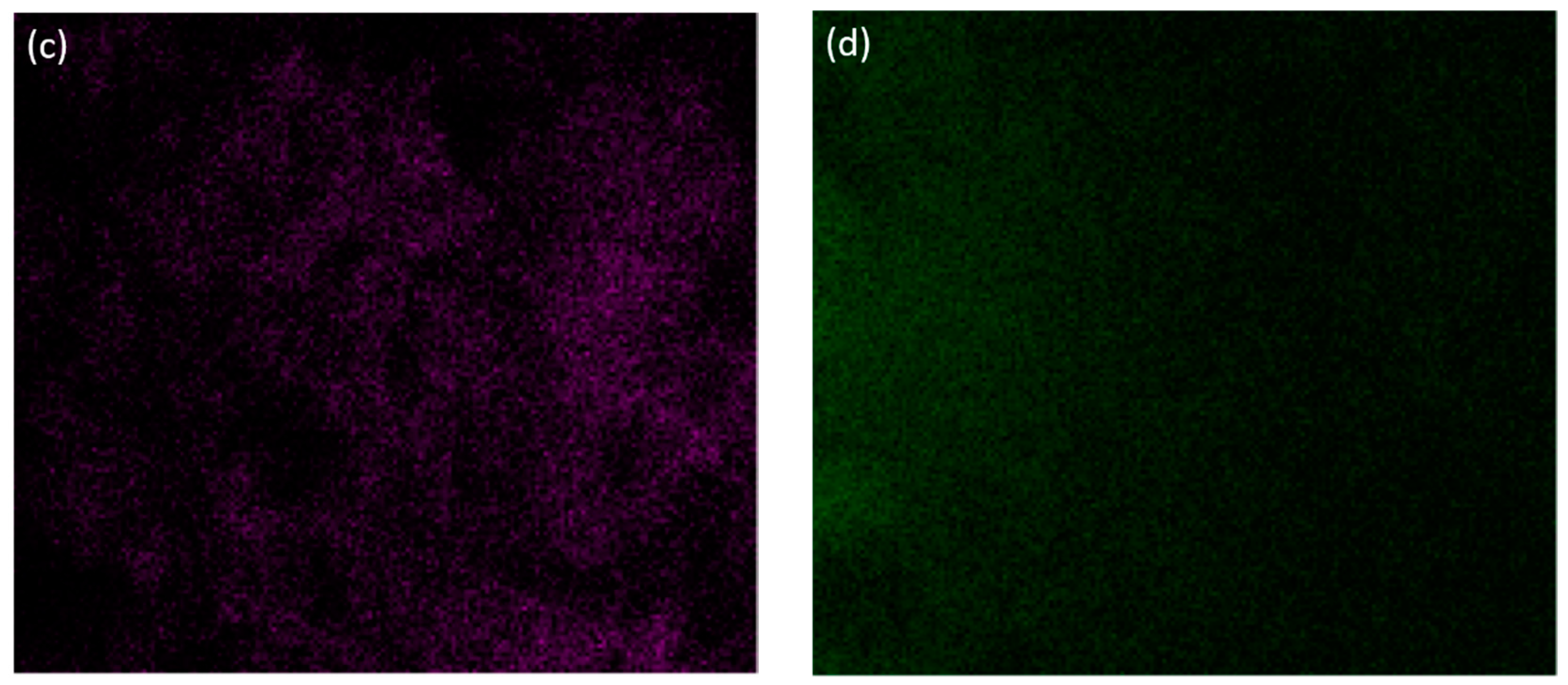
Scanning electron microscope (SEM) analysis was used for further insight into the excellent performance of the sulfur cathode with the Thiokol binder. The SEM images in
Figure 3a,b show the cathode morphology before and after cycles with the Thiokol binder. It is obvious that sulfur particles with a size of around 1µm disperse evenly in the composite before cycling. While after 50 cycles, no intact sulfur particle can be found since they have been taken advantage of and the reaction products distributed evenly in the cathode. Due to the formation of SEI (solid electrolyte interface) and the infiltration of electrolyte during the cycling, the particle morphology has been changed from independent to connected ones, which could lead to an improvement of the ionic migration. The Energy Dispersive X-Ray Spectroscopy (EDX) of the element carbon and sulfur (
Figure 3c,d) also shows their homogeneous distribution after cycling. This indicates that the electrode structure is stable during the cycling.
Figure 4a shows the photos of the polysulfides in the electrolyte without and with different binders. It can be seen from
Figure 4a that the color of the disperse system in (1) and (2) are almost the same, while for (3), the color gets lighter to (1) and close to (4). Considering that the color of polysulfides gradually deepens from colorless to orange as the value of
x in Li
2S
x increases, the effect of reducing long-chain soluble polysulfides is obvious for Thiokol and invisible for PVDF. This demonstrates that Thiokol has a stronger ability in keeping long-chain soluble polysulfides from shuttling through the battery.
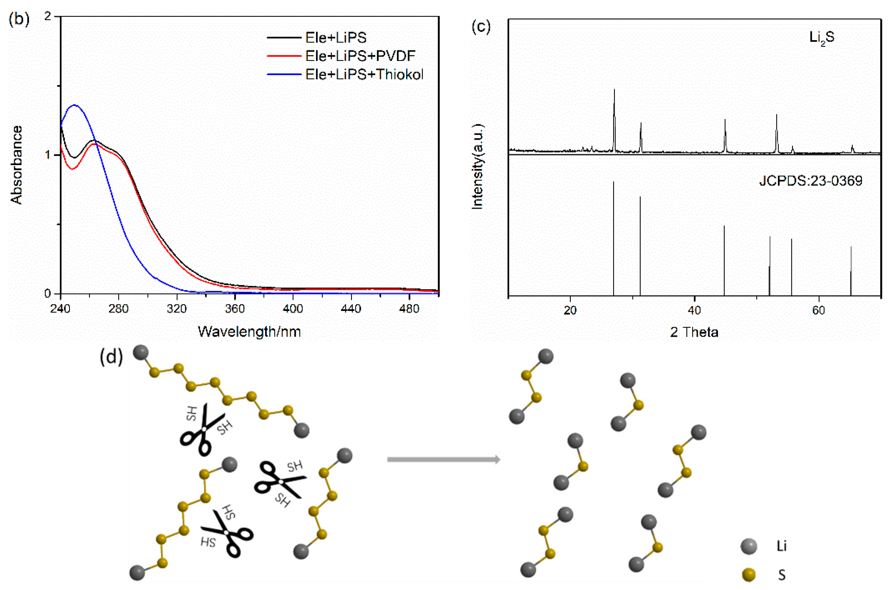
Figure 4b compares the UV–visual spectroscopy of different solutions of soluble Li
2S
x in electrolyte (electrolyte as reference). The peaks at 262 nm correspond to the long-chain soluble polysulfides, while the peak at 250 nm is assigned to short-chain insoluble polysulfides [
27]. It is clear that the addition of PVDF does not change the peak position of original solution, while the peak moves to lower wavelength upon the Thiokol addition. Thus, it is reasonably deduced that that Thiokol could turn the long-chain soluble polysulfides into short-chain insoluble polysulfides, thus effectively retraining the shuttle effect of soluble lithium polysulfides.
Figure 4c shows the XRD pattern of the washed precipitate from the mixture in
Figure 4a (2) after mixing for 2 h. Several diffraction peaks can be observed and are well matched with the crystalline data of Li
2S (JCPDS: 23-0369), suggesting a generation of Li
2S product in this system. The ex situ XRD result confirmed the reaction between the long-chain polysulfides and Thiokol.
Figure 4c shows the schematic illustration of reactions about polysulfides in the cathode.
Reaction (1) could also be used to explain the function of Thiokol. Long-chain soluble Li2Sx (x = 4, 6, 8) could react with Thiokol since the existence of thiols and be divided into short-chain insoluble Li2Sy (y = 1, 2). The shuttling of soluble polysulfides was restrained in that case.


