Article

Robust Template-Based Watermarking for DIBR 3D Images

School of Computing, Korea Advanced Institute of Science and Technology, Daejeon 305701, Korea
*
Author to whom correspondence should be addressed.
Appl. Sci. 2018, 8(6), 911; https://doi.org/10.3390/app8060911
Submission received: 9 May 2018 / Revised: 27 May 2018 / Accepted: 27 May 2018 / Published: 1 June 2018

Abstract

:
Several depth image-based rendering (DIBR) watermarking methods have been proposed, but they have various drawbacks, such as non-blindness, low imperceptibility and vulnerability to signal or geometric distortion. This paper proposes a template-based DIBR watermarking method that overcomes the drawbacks of previous methods. The proposed method exploits two properties to resist DIBR attacks: the pixel is only moved horizontally by DIBR, and the smaller block is not distorted by DIBR. The one-dimensional (1D) discrete cosine transform (DCT) and curvelet domains are adopted to utilize these two properties. A template is inserted in the curvelet domain to restore the synchronization error caused by geometric distortion. A watermark is inserted in the 1D DCT domain to insert and detect a message from the DIBR image. Experimental results of the proposed method show high imperceptibility and robustness to various attacks, such as signal and geometric distortions. The proposed method is also robust to DIBR distortion and DIBR configuration adjustment, such as depth image preprocessing and baseline distance adjustment.

1. Introduction

Three-dimensional (3D) content has been steadily increasing in popularity because of its excellent lifelike appearance. With the recent development of 3D display technology, many new 3D applications have appeared to maximize realism, such as head-mounted displays, 360° virtual reality and ultra-high definition 3D content. Consequently, interest in 3D content and in the 3D market itself have both increased greatly.
Methods of representing 3D content are divided into stereo image recording (SIR) and depth-image-based rendering (DIBR). SIR stores the left and right views (as human eyes do) and provides a high-quality immersive view; however, this has many limitations, including a large data size, fixed depth, high cost and difficulty with multiple camera settings. Meanwhile, DIBR is a rendering method that creates various virtual viewpoint images using center and depth images [1,2,3,4]. The DIBR method has two main advantages: (1) the DIBR system is able to easily save and transmit 3D content, because it requires less data compared to SIR; (2) the DIBR system can provide various viewpoints, since it allows us to adjust the 3D configuration. These advantages have led to DIBR technology being employed in 2D-to-3D conversion [5,6,7,8,9,10] and auto-stereo [11,12] and multi-view stereo [13,14,15,16,17], which provide various viewpoints depending on the user’s position
Copyright protection techniques for DIBR content have received considerable attention due to DBIR’s important role and significant 3D content market growth. A typical copyright protection technique is watermarking, but many conventional two-dimensional (2D) watermarking techniques are difficult to apply to DIBR content. In the DIBR system, center image pixels are partially moved along the horizontal axis with distance depending on the depth image, using a process called non-linear geometric distortion. Watermarks inserted in the center image are strongly distorted and cannot be extracted.
Hence, several watermarking methods have been proposed as being robust to the DIBR process. Lin et al. proposed a method of embedding watermarks by predicting pixels’ moving distance [18]. Protecting the center image and both the left and right images required superimposing and embedding three watermarks. This method has a low bit error rate (BER) against the DIBR process and common distortions, such as JPEG or additive noise. However, this method is vulnerable when the depth information is modified, such as in depth image preprocessing or the change of baseline distance, since the moving distance for pixels during the DIBR process is predicted with unmodified depth information. Additionally, this method is vulnerable to geometric attacks due to the characteristics of the discrete cosine transform (DCT) domain.
Franco-Contreras et al. proposed a method of averaging the luminance of an image in the horizontal direction and then inserting a watermark in the averaged vector [19]. This method is robust against DIBR and signal processing attacks, but has the disadvantage of not considering geometric transformations.
Kim et al. suggested a watermarking method that employed quantization on dual tree complex wavelet transform (DT-CWT) domain coefficients [20]. The method used directional coefficients that were not significantly changed by the DIBR process. Row-wise quantization was performed to provide robustness to horizontal pixel shifts. The method showed robustness to DIBR; JPEG compression; image scaling; and DIBR configuration adjustments, such as depth image preprocessing and baseline distance changes. However, it was vulnerable to noise addition and geometric distortions.
Wang et al. [21], Miao et al. [22] and Cui et al. [23] proposed a DIBR watermarking method that used the scale-invariant feature transform (SIFT). The SIFT based-watermarking systems found similar parts between the center image and the synthesized image using a SIFT descriptor and then inserted the watermark into those parts. Because of the object matching with SIFT, these methods were robust to DIBR distortion. Additionally, the methods showed high robustness to both general signal distortions and geometric distortions. However, SIFT-based DIBR watermarking methods need SIFT descriptors during watermark extraction. These methods cannot extract watermarks blindly; therefore, SIFT-based watermarking methods are less practical than full-blind watermarking systems.
Rana et al. defined a dependent view region, which is a common area of the left and right eye images, and inserted a watermark using the DC coefficients of the DCT in the dependent view region [24]. This method achieved robustness against DIBR, JPEG compression and various noise attacks. Rana et al. also proposed a 3D video watermarking technique [25]. This method exploits the shift invariance and the directional property of the 2D DT-DWT to insert a watermark. This technique showed high invisibility and high robustness against 3D-high efficiency video coding compression, as well as DIBR attacks. However, neither of these methods consider geometric distortions.
Asikuzzaman et al. proposed a DT-CWT-based video watermarking method using color channels [26,27]. The method inserted a watermark into the U channel of the YUV color space and inserted the same watermark rotated 180° into the V channel. They showed that the method was robust to DIBR, due to the DT-CWT domain characteristics; and geometric attacks, such as scaling and rotation, since the U and V channels suffer the same geometric transformation. However, if the image center were changed due to attacks such as crop or translation, the watermark could not be detected, and under geometric distortion, it could only determine whether a watermark had been inserted or not, i.e., an on/off switch. Therefore, its application was somewhat limited.
Various templates have been proposed that are robust against geometric attacks [28,29,30,31]. However, these are only designed to be robust to linear distortions, such as affine transforms, and so are not robust to DIBR, which is a non-linear distortion, as discussed above.
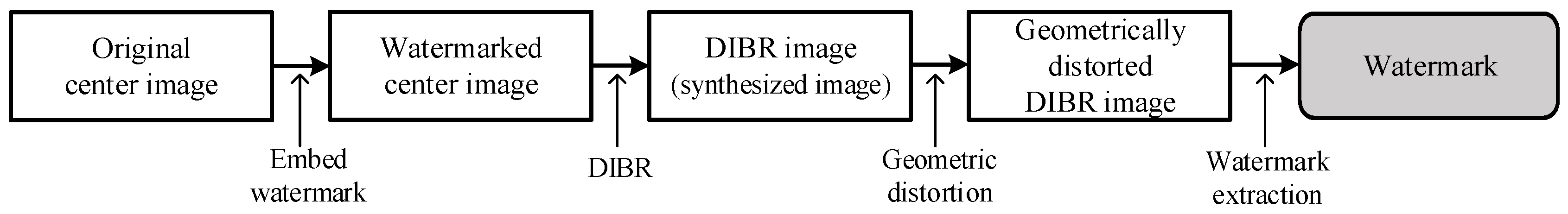
The results of previous works show that blind watermarks have great difficulty surviving in geometrically-distorted DIBR images, because the watermark must be robust to both DIBR and geometric attacks, as shown in Figure 1. The combination of non-linear and linear deformation severely damages most watermarking domains. Therefore, it is desirable to solve this problem by combining two watermarking methods that have different characteristics, rather than using a single watermarking method.
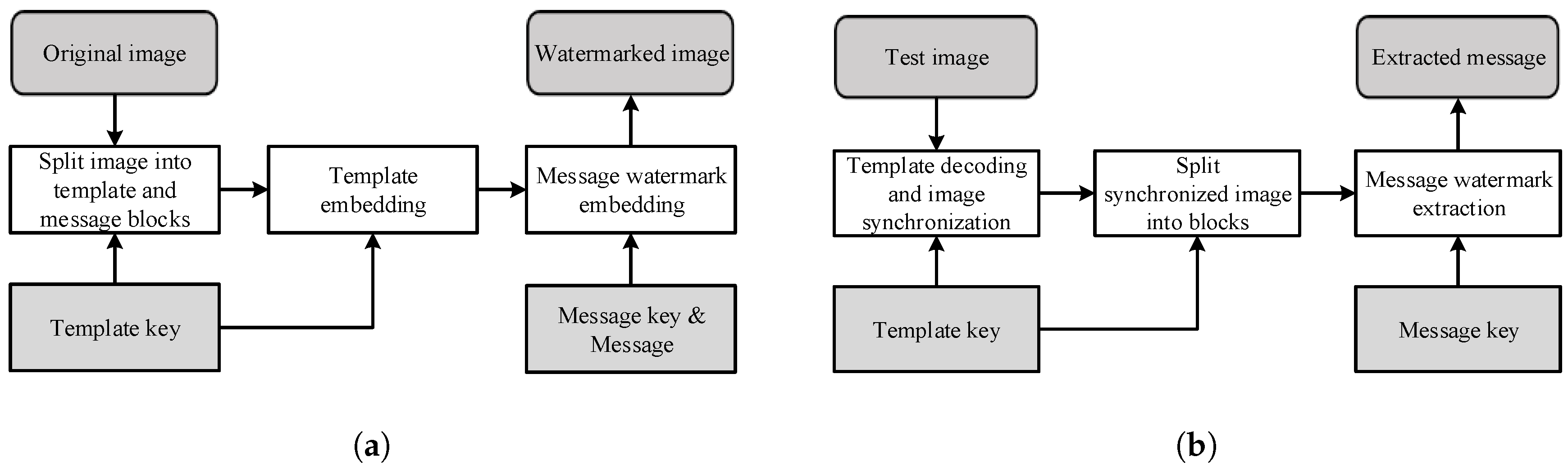
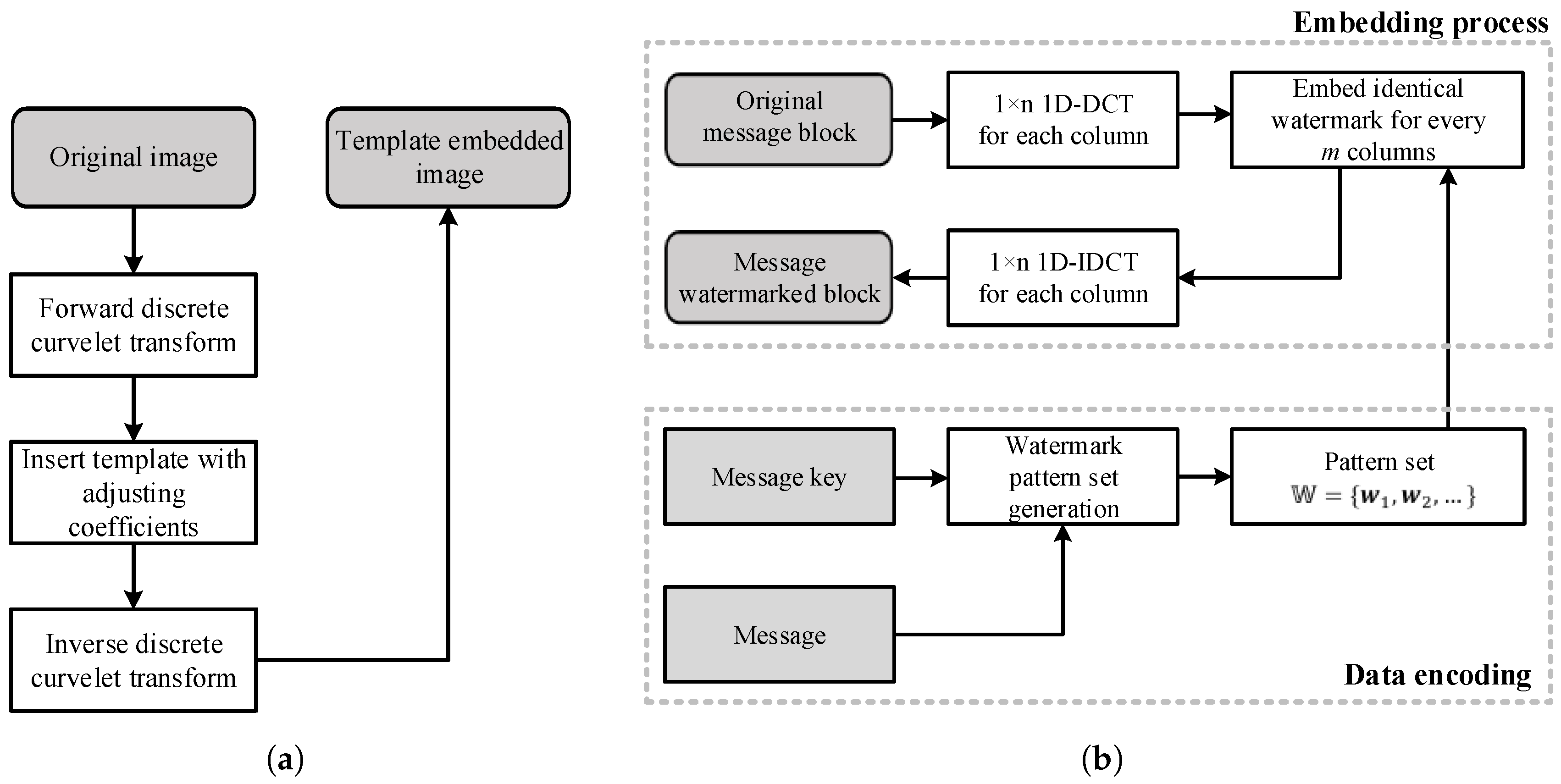
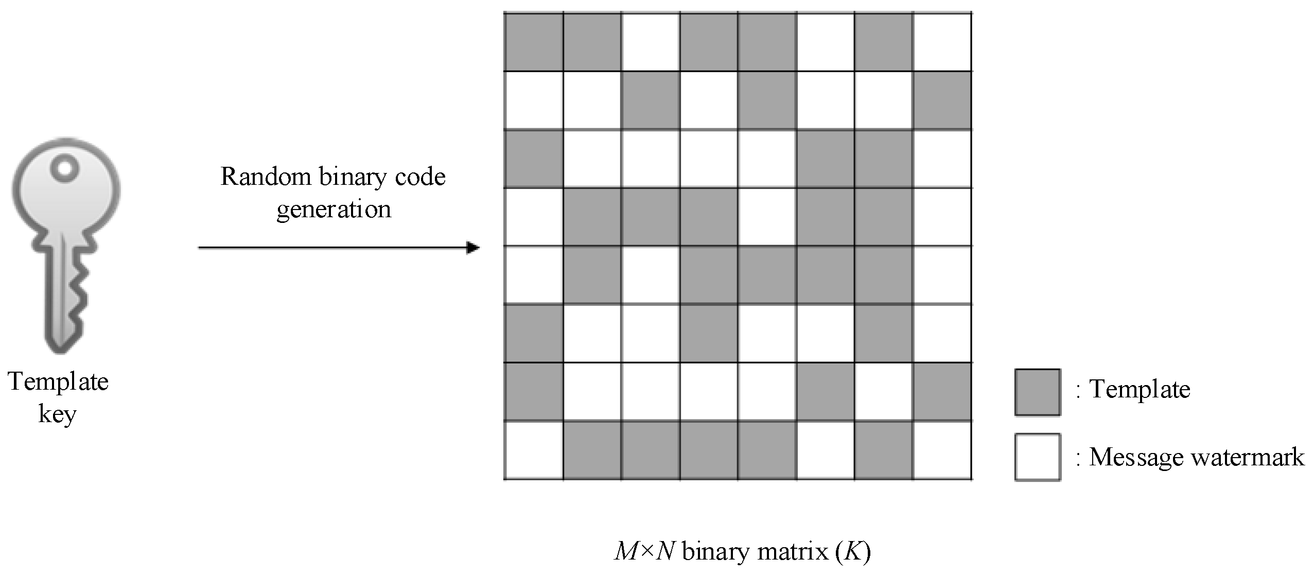
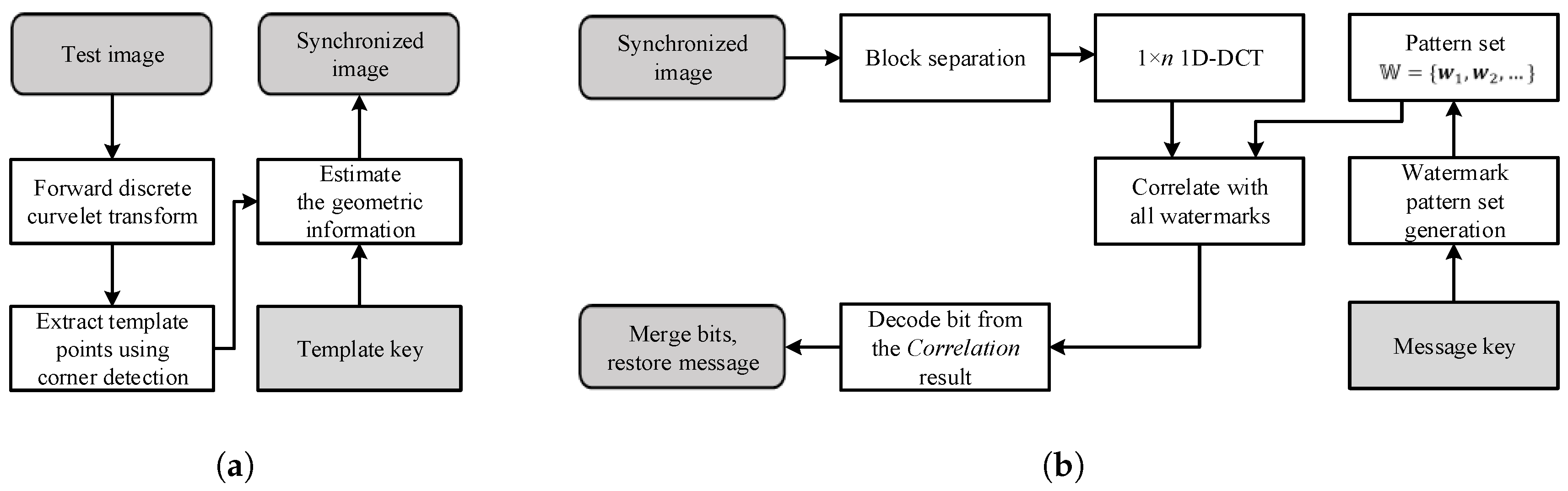
This paper proposes a blind template-based watermarking system combining templates and message watermarks. The role of the template is to restore geometric distortion without being destroyed by the DIBR attack. The template is inserted into the curvelet domain in the form of peak points, and geometric distortion is estimated using the modified iterative closest point (ICP) method. The message watermark inserts and detects messages in the DIBR image. The proposed message watermark is inserted into the 1D-DCT domain, and the message is extracted from the DIBR image after geometric distortion recovery using the proposed template. The message watermark inserts the same information along the horizontal direction in the 1D-DCT domain, and the inserted message watermark is invariant to DIBR due to 1D-DCT linearity.
Experimental results showed that the proposed method has both high invisibility and robustness against various attacks. It achieved excellent scores in visual quality tests and low BER for common signal distortions, such as noise addition and JPEG compression. The watermarking system also exhibited good robustness against geometric distortions, a point of vulnerability in previous approaches, and excellent robustness against DIBR attacks and DIBR configuration adjustments.
This paper is organized as follows. Section 2 describes the DIBR system and curvelet transform, which are fundamental techniques for the proposed scheme. Section 3.1 demonstrates the main idea of the proposed watermarking method. The watermark embedding and extraction processes are presented in Section 3.2 and Section 3.3, respectively, and the experimental results and conclusion are given in Section 4 and Section 5, respectively.

2. Background

This section presents DIBR and the curvelet transform, fundamental techniques of the proposed watermarking system. First, the DIBR process is briefly introduced and DIBR analysis presented, and then, we provide an introduction to and analysis of the curvelet transform.

2.1. DIBR Process

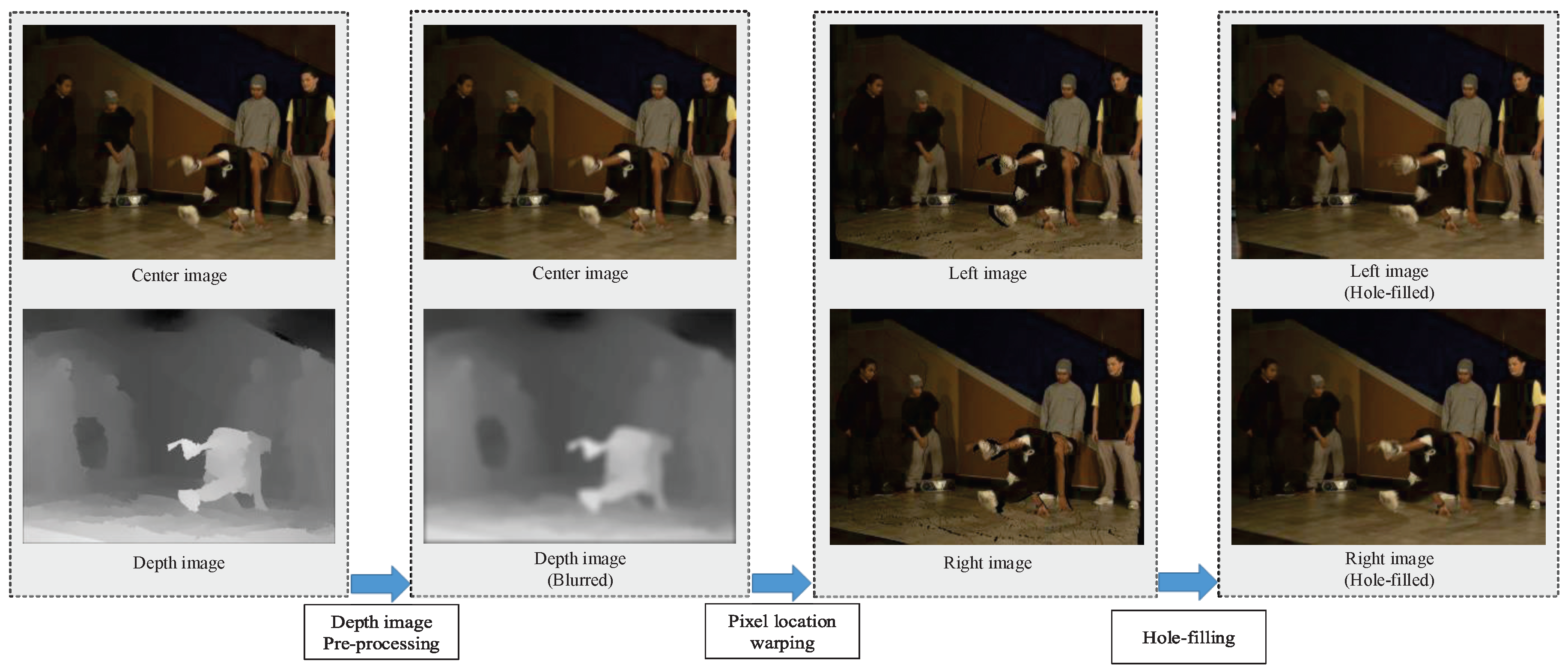
The whole DIBR process is shown in Figure 2. DIBR consists of three steps: depth image preprocessing, pixel location warping and hole-filling.
Depth image preprocessing, the first step, improves the quality of the rendered image by reducing the number of holes [32,33,34]. When the viewpoint is moved by the DIBR, an area where no pixel information exists is generated. These areas, referred to as holes, are the main cause of 3D image quality degradation. Holes occur mainly when the depth difference between two adjacent pixels is large. Hence, the image quality can be improved by reducing the number of holes through depth image smoothing.
Pixel location warping, the second step, changes the position of pixels along the horizontal direction, allowing users to feel a 3D effect. The warping equation is as follows,
x L = x C + t x 2 × f Z , x R = x C t x 2 × f Z
where x C is the pixel position on the x-axis of the center image, x L and x R are the pixel positions on the x-axis of the left view and the right view, respectively, t x is the baseline distance, which means the distance from the center axis to the left and right, f is the focal length and Z is the value of the depth image. During warping, two or more pixels can overlap in one position. In this situation, the highest Z value of a pixel has to be selected to prevent an unnatural image.
The last step is hole-filling, which creates pixel values in holes caused by pixel location warping. There are several hole-filling techniques, such as interpolation and inpainting. This is a field that is constantly studied in pursuit of a more natural image [4,35,36].

2.2. Analysis of DIBR Attack

In the DIBR process, pixels are only translated horizontally, where the translation magnitude is determined by the depth. Similar to the cover model being considered as random, the depth image is also close to a random signal [37]; hence, the pixel’s moving distance can also be assumed to be random. Consequently, the pixels move irregularly, unlike in common translation. Thus, the 2D transformed domain coefficients are distorted by DIBR.
The watermark damage caused by DIBR can be confirmed by the average energy change of the middle frequency at which the watermark is inserted, since the average energy is the basis of the watermark embedding energy.
Table 1 shows the average energy change between center and synthesized DIBR image coefficients. DIBR parameters used in this test were as recommended by [3], and average energy change was defined as:
M S E ( O , S ) mean ( O 2 )
where O and S are the transformed domain’s coefficients for the original and synthesized images, respectively; and MSE is mean squared error. The various transform domain coefficients’ energy is severely impaired by DIBR. Therefore, the watermark energy, inserted into the transform domain’s coefficients, is also damaged, and watermarks damaged by more than 40% are difficult to detect.
However, the average energy change of the Haar discrete wavelet transform (DWT) is reduced to 4% if the distorted coefficients are matched with the undistorted coefficients using the depth image. This is because the wavelet series represent the frequency information of the small spatial block, such as 2 × 2, 4 × 4, ⋯.
If the image is divided into small blocks, some of these will be undistorted, since the depth is similar between adjacent pixels within an object. If all depth values are the same in the block, pixel moving distances are all the same. DIBR is treated like a common translation for this case. A smaller block size implies a greater percentage of uncorrupted blocks, as shown in Table 2 for the example of 1800 synthesized DIBR images. Similar to the previous average energy change test, this test also used the recommended DIBR parameters from [3].
Since DCT and discrete Fourier transform (DFT) express a global frequency that does not include spatial information, the amount of average energy change after matching is still high. In other words, it can be seen that the magnitude of the coefficients is damaged in DCT and DFT, but the magnitude of the coefficients is maintained in DWT.
In summary, the following two properties of DIBR can be identified: (1) the pixel is moved only in the horizontal direction, and the moving distance is determined by the depth; (2) the percentage of undistorted blocks is high with a small block size. Due to the second property, the wavelet series are robust to DIBR.

2.3. Curvelet Transform

The curvelet transform is a multi-scale decomposition-like wavelet transform, and the curvelet represents the curve shape for the various directions in the spatial domain [38,39,40,41]. The curvelet transform is developed to improve the limitation of wavelet-based transforms and can represent edges more efficiently than conventional wavelet-based transforms. Moreover, curvelet bases cover all frequencies in contrast to other directional multi-scale transforms, such as the Gabor and ridgelet transforms [42]. The curvelet transform is expressed as follows,
C ( g , l , k ) : = f , φ g , l , k = R 2 f ( x ) φ g , l , k ¯ d x = 1 ( 2 π ) 2 f ^ ( ω ) U g ( R θ l ω ) e i x k ( g , l ) , ω d ω ,
U g ( r , θ ) = 2 3 g / 4 W ( 2 g r ) V 2 g / 2 θ 2 π ,
In (3), C is the curvelet coefficient, g = 0 , 1 , 2 , is the scale parameter, l is the rotation parameter and k = ( k 1 , k 2 ) is the translation parameter. U g is a “wedge”-shaped frequency window represented in (4). R θ is the rotation operator, and θ l = 2 π · 2 g / 2 · l . In (4), W and V are the radial and angular windows, respectively.
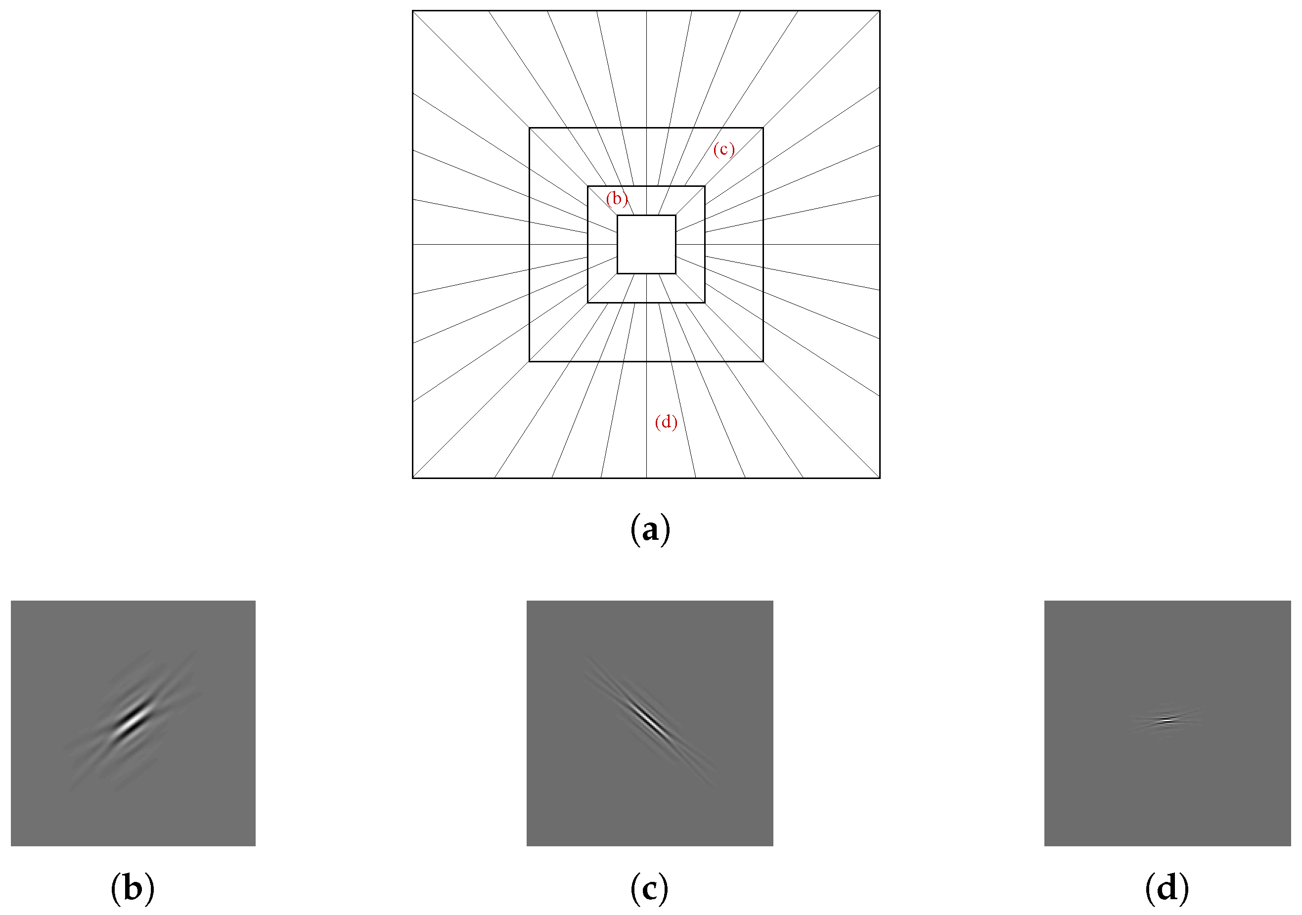
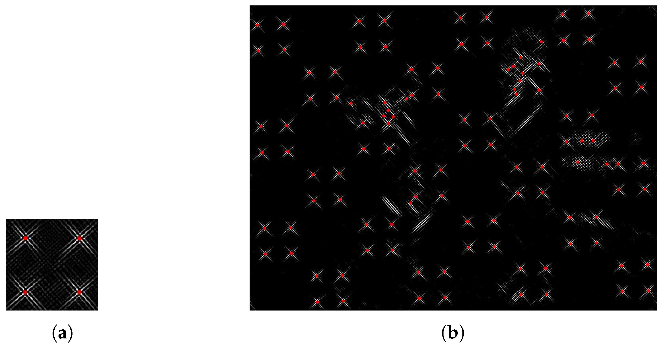
The curvelet is illustrated in Figure 3. Figure 3a illustrates the tiling of the curvelet in the frequency domain, and the curvelet shape in several directions and scales in the spatial domain is shown in Figure 3b–d.
As shown in Equation (3) and Figure 3, the curvelet represents frequency information of a small spatial block similarly, so the curvelet is also not distorted by DIBR. In addition, energy conservation is better with the curvelet transform than with conventional Haar DWT when image rotation occurs [43]. For example, when the image rotates 10 degrees, the energy inserted into Haar DWT is reduced to 50%, but that inserted into the curvelet is maintained up to 85%. In the case of scaling attack, energy is well maintained in most DWT.
In summary, the curvelet transform is suitable for use as a template due to its robustness to DIBR and geometric transform.

3. Proposed Method

3.1. Main Idea of the Proposed Method

The overall flow of watermark embedding/extraction is shown in Figure 4. As shown, the proposed watermarking system consists of a template and message watermark. This section describes the characteristics and roles of the template and message.
The DIBR watermarking system must be robust to both DIBR and geometric attacks, as shown in Figure 1. The proposed method inserts a template into a curvelet domain robust against DIBR and geometric distortions. The inserted template enables restoring the image from geometric distortion without being destroyed by DIBR. Geometric distortion can be restored by inserting the template in peak point form and matching detected peaks with ground-truth positions, which can be obtained from the template key in the detection step.
However, although the peak matching method can recover global geometric distortion that occurs across the entire image, DIBR distortion cannot be recovered because it is treated as horizontal error. In addition, the peak point form template cannot insert messages. To address these problems, we designed an invariant message watermarking technique against DIBR, where DIBR deformations that cannot be restored by the template are handled by the message watermark. Message watermarks without templates are vulnerable to geometric attacks, but combining the advantages of the template and message watermark allows a robust DIBR watermarking system.
In summary, the template and message in the proposed watermarking system complement each other’s weaknesses. The curvelet with robustness to DIBR is utilized as a template to restore images from geometric attacks. The message watermark inserted in the 1D-DCT domain resolves the unrecovered damage caused by DIBR. The message watermark itself is not robust to geometric attacks, but images that have suffered geometric attacks can be restored using templates. The roles of templates and message watermarks are summarized in Table 3.

3.2. Proposed Watermark Embedding Method

This section gives a detailed description of the proposed watermarking procedure. The whole embedding process is presented in Figure 5.

3.2.1. Block Separation

If the template and the message watermark are inserted at the same position, the signals interfere with each other, and the robustness is degraded. To avoid overlapped insertion, the image is spatially divided into M × N blocks, as shown in Figure 6. The set of blocks is defined as B, and the template and message are inserted into the different blocks.
A random binary code is generated using the template key, and this code is then used to generate a 2D binary matrix, K, of size M × N , which determines whether each block is a template or message watermark block in an image divided into blocks. To match the number of template blocks with the number of message watermarks, the average (K) should be 0.5. The template key is only used to determine the position of the template blocks, independent of the watermark key to be used later. Therefore, the template key has no effect on the message watermark.
The following rules distinguish the roles of the blocks.
B ( x , y ) = Template block , if K ( x , y ) = 1 Watermark block , if K ( x , y ) = 0
where x and y are the horizontal and vertical coordinates of B and K, 0 ≤ x < M and 0 ≤ y < N.

3.2.2. Template Embedding

Since the curvelet coefficients contain spatial information, the template block position can be extracted from the curvelet coefficients. Therefore, the entire image is transformed into the curvelet domain without requiring a block-based curvelet transform. We then insert the peak point templates into the curvelet coefficients.
As shown in Figure 7, four peak points are inserted into one template block. If the number of peak points is too small, the robustness drops, and if there are too many points, the visual quality drops. Experimentally, four points were appropriate.
The template embedding process is divided into three steps:
(a)
Forward curvelet transform: The forward curvelet transform is applied to the whole image.
(b)
Peak points’ insertion: Select two directions of a curvelet, l 1 and l 2 , with scale value g. l 1 and l 2 are selected such that they differ by 90°, to increase the detection rate by corner detection in the template extraction step, and g should be selected to be a middle frequency, as a compromise between invisibility and robustness. As discussed above, four peak points are inserted into one template block,
C m ( g , l 1 , k ) = C ( g , l 1 , k ) · α t + β t C m ( g , l 2 , k ) = C ( g , l 2 , k ) · α t + β t
where C m is the modified curvelet coefficient, C is the original curvelet coefficient, α t and β t represent the strength of the inserted template and k is the location of the template point.
(c)
Inverse curvelet transform: The inverse curvelet transform is applied to the modified coefficients.

3.2.3. Message Watermark Embedding

The message is inserted into the 1D-DCT domain using the spread spectrum method [44]. If a watermark having the same information in the horizontal direction is inserted into the 1D-DCT, invariance can be obtained against DIBR due to the first property in Section 2.2. The 1D-DCT watermark insertion equation is as follows,
DCT ( I i : ) = DCT ( I i : ) + w ,
where i = 1 , 2 , , m , w = [ w 1 , w 2 , w n ] T is the watermark signal and m , n are the horizontal and vertical sizes of the block, respectively. I i : denotes the i-th column of the original block; I i : denotes the i-th column of the watermarked block; and DCT denotes the 1D-DCT.
The DIBR attack is applied in the spatial domain, not in the transformed domain. Therefore, the inverse DCT (IDCT) is performed to check the change of the inserted watermark in the spatial domain. Using the IDCT, Equation (7) can be rewritten according to the linearity of the DCT as follows,
I i : = IDCT ( DCT ( I i : ) ) = IDCT ( DCT ( I i : ) + w ) = I i : + IDCT ( w ) = I i : + v ,
where v = [ v 1 , v 2 , , v n ] T denotes the inverse transformed watermark.
The signal v is inserted as the same information in all columns of the spatial domain. This means that the embedded patterns from the j-th row have the same v j signal. Therefore, embedded watermark v has the following DIBR invariance,
D ( [ v , v , , v ] ) = v 1 v 1 v 1 v 2 v 2 v 2 v n v n v n = [ v , v , , v ]
where D ( · ) is the DIBR process described in Section 2.1.
Since DIBR only translates pixels in the horizontal direction, v is not deformed. Therefore, the watermark can be extracted in the frequency domain as follows,
DCT ( D ( I i : ) ) = DCT ( D ( I i : + v ) ) = DCT ( D ( I i : ) + D ( v ) ) = DCT ( D ( I i : ) + v ) = DCT ( D ( I i : ) ) + DCT ( v ) = DCT ( D ( I i : ) ) + w .
Hence, w can be extracted in the frequency domain without being damaged by DIBR in the extraction process.
To compensate for the capacity decrease caused by template insertion, a data coding technique can be utilized to insert more than 1 bit per block [37]. The message watermark embedding process is divided into four steps as follows.
(a)
Column-by-column 1D-DCT: Each column of the message block is transformed by 1D-DCT.
(b)
Data encoding: A pseudo random watermark pattern set (i.e., a set of watermark patterns) is generated. The length of the set is determined by the user, and the capacity of the block is determined according to the length. For example, to represent four bits of information per block, 16 (i.e., 2 4 ) unique watermark patterns are generated [45].
(c)
Watermark embedding: The proposed method embeds the watermark based on the spread-spectrum [45]. The generated watermark pattern set w b = w b 1 , w b 2 , , w b L is embedded into the middle frequency of the DCT signal s = s 1 , s 2 , , s L compromising both robustness and invisibility. The embedding equation is as follows,
s i = s i + α m | s i | w b i
where i is the block column, 1 i L , L is the length of the watermark signal, s = s 1 , s 2 , , s L is the original signal, s = s 1 , s 2 , , s L is the watermarked signal, α m is the message watermark strength, w b L is the watermark pattern and b is the message inserted into the block. For example, if b = 7 (111 in binary form), the message inserted in the block is 111 (in this case, the pseudo-random pattern set length = 2 3 ). The embedding step (11) is repeated for all columns in the block.
(d)
1D-IDCT: The watermarked block is reconstructed by 1D-IDCT.

3.3. Proposed Watermark Extraction Method

This section describes the details of the proposed watermark extraction method. The overall process is illustrated in Figure 8. Before extracting the messages, the image must be synchronized using a template.

3.3.1. Template Decoding

(a)
Forward curvelet transform: The curvelet transform is applied to the test image.
(b)
Extract template points using corner detection: A peak was inserted into the l 1 and l 2 pair in the embedding step, with a 90° difference at each template point. Due to curvelet filter characteristics, the peak point spreads in a straight line in the corresponding direction. Therefore, the peak point is represented by an “X” shape when only coefficients of l 1 and l 2 are extracted, as shown in Figure 9, and can be found by corner detection. This paper employed Harris corner detection, but similar approaches would also suffice.
(c)
Estimate the degree of geometric deformation by exploiting modified ICP: The ICP method estimates the parameters of geometric distortion when there is no matching information of two point clouds. This method assumes that the closest points between the two point clouds match each other and repeats the process of minimizing the error [46].
This paper modifies the ICP to suit the problem in need of solving. Since the DIBR image has an error in the horizontal information, the weight of the horizontal distance error is set to 1/2.
Geometric distortion parameters are estimated using the modified ICP method, comparing detected corner points with the template point ground truth. The template ground truth can be generated using the key as in the embedding step.
(d)
Recover the test image using the estimated geometric distortion parameters.
If the degree of geometric transformation is large, the direction in which the template was inserted may have changed. For example, if the image was significantly rotated, the template inserted in the direction pairs l 1 and l 2 is moved to the direction pairs l 1 + 1 and l 2 + 1 . In this case, the template decoding process is repeated for all direction pairs, and the estimated geometric parameters with the lowest ICP error are used.

3.3.2. Message Watermark Extraction

The message is extracted from the image recovered by the template. Message extraction consists of six steps:
(a)
Split the synchronized image into blocks: Divide the recovered image into blocks as in the embedding step.
(b)
Column-by-column 1D-DCT: The same process applied in the embedding step is applied.
(c)
Correlation: The correlation is conducted as follows,
C o r r ( b ) = s · w b L = 1 L i = 1 L s i · w b i
The notations are identical to those in the embedding step.
(d)
Bit decoding: Bits are decoded from the correlation result. For example, if the correlation value with w 3 i is the highest, then the bit decoded from the i-th column is 011. The length of the bit is determined by the length of the watermark pattern set, and in this case, the watermark pattern set length = 2 3 . Different bits may be decoded for each column, and the majority voting method is used to determine the bit of the block.
(e)
Restore messages by merging the bits: The messages are recovered by merging the bits extracted from each message block.

4. Experimental Results

This section evaluates the proposed method’s performance in terms of imperceptibility and robustness to various distortions. The proposed method was compared with other blind DIBR image watermarking systems, specifically Lin’s method [18] and Kim’s method [20]. The bit capacity of all methods was set to 64.

4.1. Experiment Setting

The test image sets were obtained from Heinrich Hertz Institute [2], Middlebury [47,48,49,50] and Microsoft Research 3D Video Datasets [51]. 
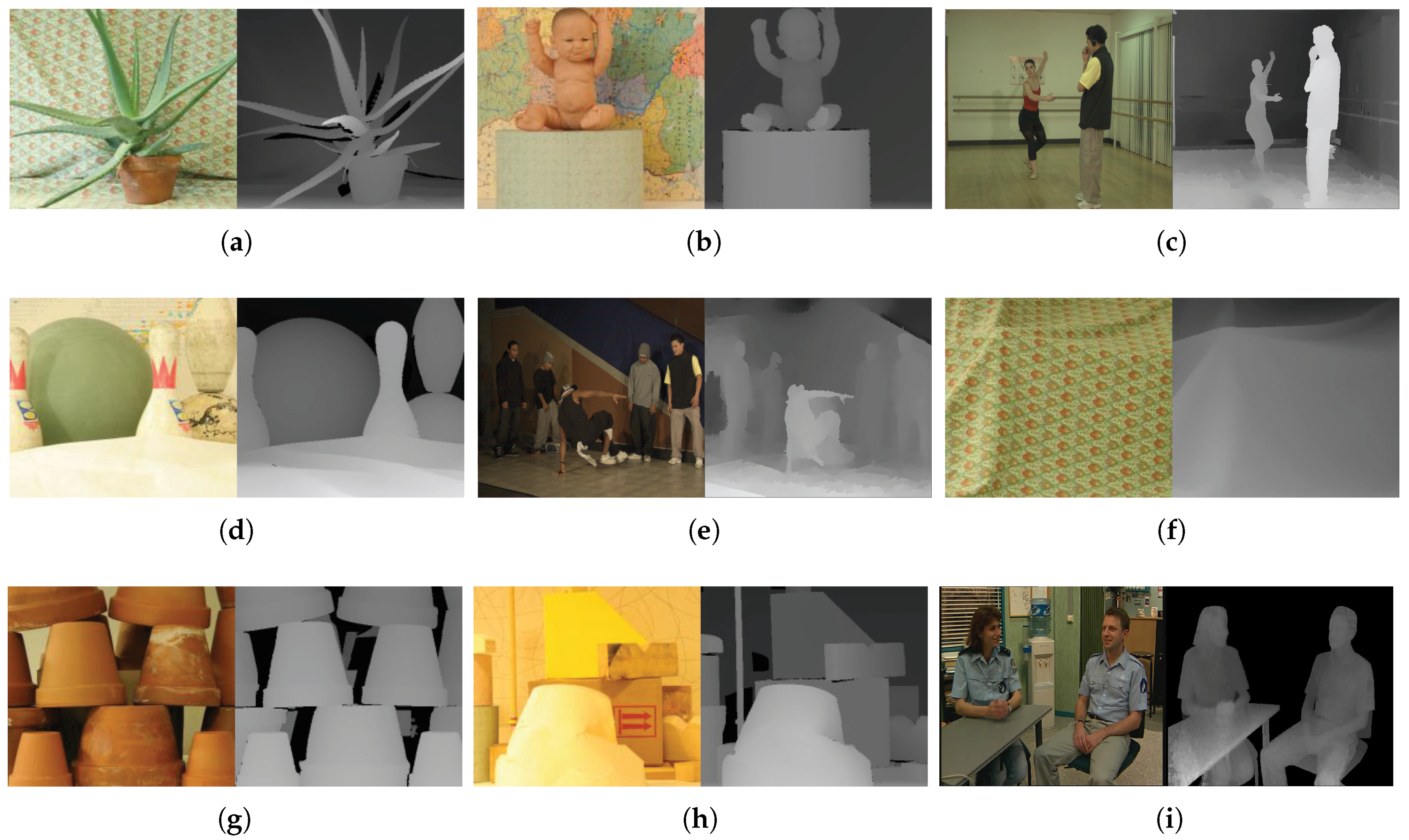
Figure 10 shows pairs of center and depth images of the test image sets. They have various resolutions from 900 × 720–1800 × 1500. The total number of images used in the experiment was about 1800.
The DIBR parameters are set to focal length f = 1 and baseline distance t x = 5 % of the image width, which are the recommended values for comfortable viewing conditions. Linear interpolation is used as hole-filling for simplicity and without loss of generality.
For Lin’s method, block size was set from 100 × 100–200 × 200 to match embedding capacity with other methods. Watermark strength was set as α = 1; watermark pattern length = 5120; and the beginning of the embedding position is the 250th coefficient of the zigzag scan order in the DCT domain.
For Kim’s method, block size was set to (w/8) × (h/8). The weighting factor for coefficient magnitude was set as W = 450, maximum quantization level m a x B i t = 2 and minimum difference between paired coefficients e r r M i n = 8. These values are demonstrated in [20].
In the proposed method, the size of each block is set set to (w/8) × (h/8). In the template embedding process, the template strengths α t and β t are set to five and 50, experimentally. In the message watermark embedding process, α m is set to 0.5; the length of the watermark pattern is 40; and the start of the embedding position is the 45th coefficient of 1D-DCT.

4.2. Image Quality

As shown in Figure 11, the quality degradation of the watermarked image is not noticeable. For more accurate image quality measurements, the peak signal-to-noise ratio (PSNR) and structural similarity (SSIM) [52] were measured. The average PSNR and SSIM are shown in Table 4.
Lin’s method has a lower PSNR despite it exploiting a spread spectrum-based watermarking method that is similar to the proposed method. Since the 2D-DCT is not invariant to DIBR, Lin’s method must insert three watermarks in a superimposed manner in order to protect the left, right and center image. For this reason, the inserted watermark energy is very large.
In Kim’s method, the images are seriously blurred, because this method cuts the coefficient off excessively. As a result, both the PSNR and SSIM values were low.
The proposed method increases imperceptibility by taking advantage of the curvelet and 1D-DCT, which are robust against DIBR. Due to this robustness, the proposed method does not require excessive insertion of the watermark. In particular, the message watermark using the 1D-DCT does not require watermark insertion in a superimposed manner, so the insertion energy can be reduced to about one-third as compared with the 2D-DCT. In addition, since the template and the message can be inserted into different blocks after dividing the block, it is possible to prevent the invisibility degradation caused by the overlapping of templates and message watermarks. For these reasons, PSNR outperforms the other methods and shows similar performance to the best methods according to SSIM.

4.3. Robustness against DIBR

Table 5 shows the results of a DIBR attack. All three methods have low BER against the DIBR attack. Since Lin’s method inserts multiple watermarks, the BER is slightly higher on the right image. The previously inserted watermark (right watermark) was disturbed by the later inserted watermarks (left and center watermarks).
The major advantage of the DIBR process is that DIBR configurations can be adjusted to suit a user’s needs. As described in Section 2.1, the user can preprocess the depth image to increase the rendered image quality. Table 6 shows robustness results for synthesized images with a preprocessed depth image. Unlike other methods, Lin’s method raised the BER. This result shows that Lin’s method is susceptible to the shift distance of the pixel, because the left and right watermarks were inserted by predicting the shift distance of the pixels.
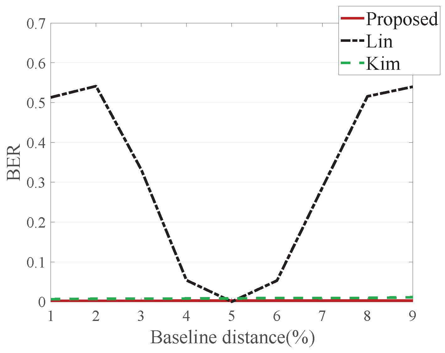
Baseline distance is another DIBR configuration aspect. Various viewpoints of an image can be synthesized depending on the baseline distance change. Figure 12 shows average BER where the baseline distance is adjusted from 1–10%. Lin’s method increases BER for the same reason as in depth image preprocessing, whereas Kim’s and the proposed method do not increase BER in the baseline distance adjustment.

4.4. Robustness against Signal Distortion

Table 7 and Table 8 show the average BER for the signal distorted center, left and right images, and 
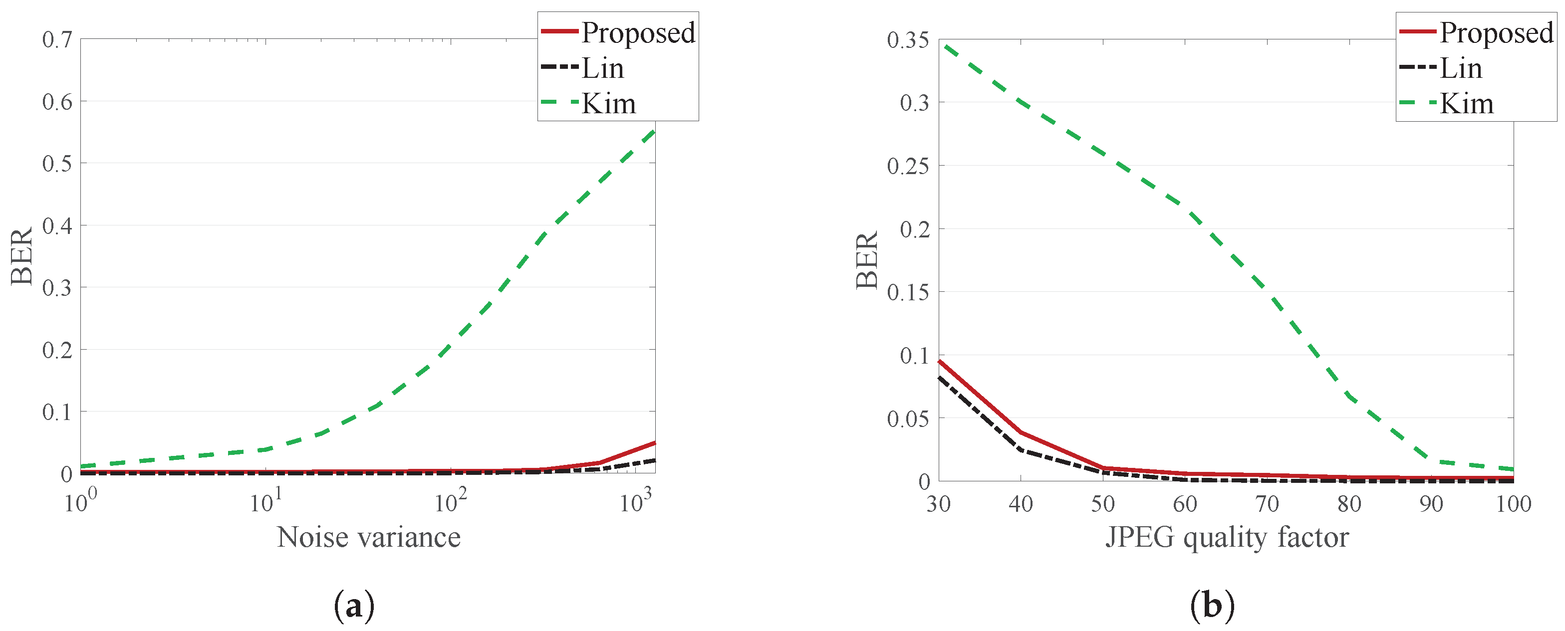
Figure 13 illustrates the average BER for the signal distorted right image.
For additive noise, Lin’s method has the best performance, and the proposed method has a slightly higher BER than Lin’s method. However, additive Gaussian noise with a variance of 2000 is a very severe attack, and such a large amount of noise barely occurs. Considering this, the proposed method is robust enough to additive noise.
For JPEG compression, the proposed method has a slightly higher BER than Lin’s method. However, since the proposed method exhibits error <0.1 for a JPEG quality factor of 30, which is very large compression, it can be considered sufficiently strong against a JPEG attack.
Meanwhile, Kim’s method is more vulnerable to signal distortion than the other methods, since the quantized DT-CWT coefficients are greatly affected by the signal distortion.

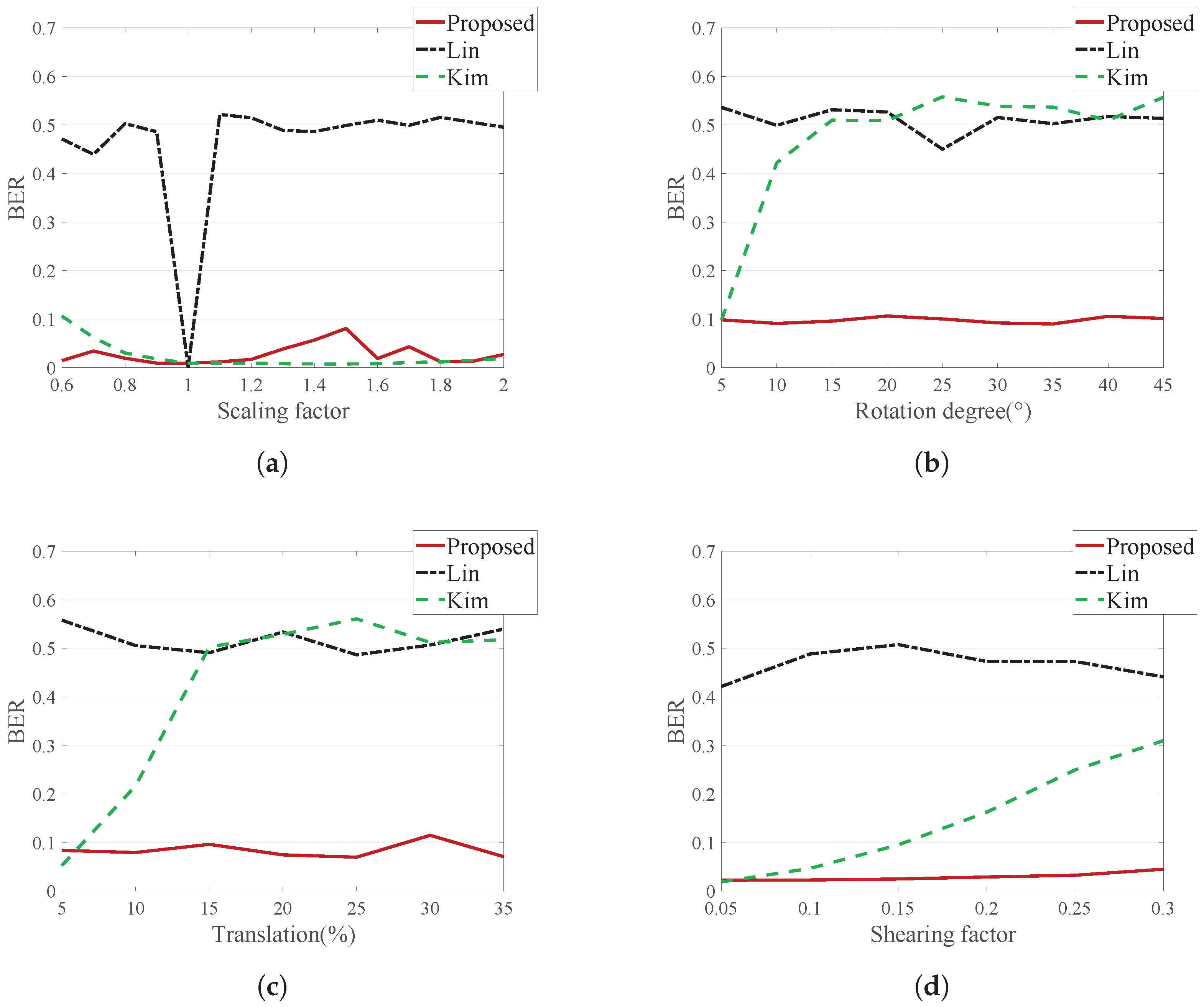
4.5. Robustness against Geometric Distortion

A robustness test against geometric distortion was also conducted with the center, left and right images. We did not consider the case where a geometric attack occurred before the DIBR attack. If a geometric attack takes place before a DIBR attack, the image becomes unnatural. For example, depth is measured horizontally, so if the DIBR is applied after the image is rotated, pixel warping will occur in an unintended direction.
Table 9, Table 10, Table 11 and Table 12 show the average BER for the geometrically-distorted center, left and right images, and Figure 14 illustrates the average BER for the geometrically-distorted right image.
Lin’s method does not show good results against geometric distortion, because this method embeds the watermark in the DCT domain, which is vulnerable to geometric distortion.
Kim’s method shows good performance against scaling, but is weak to rotation, translation and shearing. This method does not lose synchronization information in scaling. However, the rotation, translation and shearing attacks break the block synchronization. This is because the block size is specified as the ratio of the image, such as ( w i d t h / M ) × ( h e i g h t / N ) .
The proposed method shows good performance on this test, because it utilizes a template robust to geometric attacks. Since the images were recovered from geometric distortion using this template, the message watermark has a low error.
Experiments were also conducted on the combination of geometric distortion in the proposed method. This experiments were conducted by combining two of rotation, translation and scaling, and the results are shown in Table 13. Rotation with translation and scaling with translation show good results. However, when rotation and scaling occur at the same time, the watermark signal is greatly weakened, so the error is higher than with other geometric combination attacks.

5. Conclusions

Due to the advent of new 3D applications, DIBR has taken on an important role in 3D content. To protect the copyright of such content, this paper proposed a template-based DIBR watermarking system. Ensuring robustness against geometric attacks in rendered images requires that watermarks should be robust to both DIBR and geometric attacks. In order to have robustness to a combination of linear and non-linear attacks, a watermarking system was designed by combining two methods: template and message watermark. Inserting a template into the curvelet domain robust to DIBR allowed this method to restore the geometrically-distorted image. Then, the message was extracted using a 1D-DCT message watermarking method that was invariant to the DIBR. In the experimental results, the proposed method showed high image quality. In terms of robustness, it had low BER to DIBR configuration adjustment, as well as standard configured DIBR. Additionally, the results showed that the proposed method is very robust against noise addition and JPEG compression. For geometric distortion, such as scaling, rotation, translation and shearing, good performance was also demonstrated. However, this method still does not consider the robustness of video coding, which is often used in 3D video, such as high efficiency video coding (HEVC). Therefore, future work will focus on extending this method to 3D videos. In addition, since the proposed method does not use message encryption, we could further improve the security of the message by using encryption. In the future, we will investigate various other types of attack, such as copy-and-paste or transplantation.

Author Contributions

Conceptualization, W.-H.K. Investigation, J.-U.H. Methodology, W.-H.K. and J.-U.H. Resources, H.J. Software, W.-H.K. Supervision, H.-K.L. Validation, H.-U.J. Writing of the original draft, W.-H.K.

Acknowledgments

This work was supported by the National Research Foundation of Korea (NRF) grant funded by the Korea government (MSIT) (NRF-2016R1A2B2009595).

Conflicts of Interest

The authors declare no conflict of interest.

References

  1. Fehn, C. A 3D-TV approach using depth-image-based rendering (DIBR). In Proceedings of the 2003VIIP 3rd International Conference, Visualization Imaging and Image Processing, Benalmadena, Spain, 8–10 September 2003; Volume 3. [Google Scholar]
  2. Fehn, C. Depth-image-based rendering (DIBR), compression, and transmission for a new approach on 3D-TV. In Proceedings of the Electronic Imaging 2004 International Society for Optics and Photonics, San Jose, CA, USA, 21 May 2004; pp. 93–104. [Google Scholar]
  3. Zhang, L.; Tam, W.J. Stereoscopic image generation based on depth images for 3D TV. IEEE Trans. Broadcast. 2005, 51, 191–199. [Google Scholar] [CrossRef]
  4. Chen, W.Y.; Chang, Y.L.; Lin, S.F.; Ding, L.F.; Chen, L.G. Efficient depth image based rendering with edge dependent depth filter and interpolation. In Proceedings of the IEEE International Conference on IEEE, ICME 2005 Multimedia and Expo, Amsterdam, The Netherlands, 6–9 July 2005; pp. 1314–1317. [Google Scholar]
  5. Ens, J.; Lawrence, P. An investigation of methods for determining depth from focus. IEEE Trans. Pattern Anal. Mach. Intell. 1993, 15, 97–108. [Google Scholar] [CrossRef]
  6. Battiato, S.; Curti, S.; La Cascia, M.; Tortora, M.; Scordato, E. Depth map generation by image classification. In Proceedings of the Electronic Imaging 2004, International Society for Optics and Photonics, San Jose, CA, USA, 20–22 January 2004; pp. 95–104. [Google Scholar]
  7. Moustakas, K.; Tzovaras, D.; Strintzis, M.G. Stereoscopic video generation based on efficient layered structure and motion estimation from a monoscopic image sequence. IEEE Trans. Circuits Syst. Video Technol. 2005, 15, 1065–1073. [Google Scholar] [CrossRef]
  8. Tam, W.J.; Zhang, L. 3D-TV content generation: 2D-to-3D conversion. In Proceedings of the 2006 IEEE International Conference on Multimedia and Expo, Toronto, ON, Canada, 9–12 July 2006; pp. 1869–1872. [Google Scholar]
  9. Zhang, L.; Vázquez, C.; Knorr, S. 3D-TV content creation: Automatic 2D-to-3D video conversion. IEEE Trans. Broadcast. 2011, 57, 372–383. [Google Scholar] [CrossRef]
  10. Feng, Y.; Ren, J.; Jiang, J. Object-based 2D-to-3D video conversion for effective stereoscopic content generation in 3D-TV applications. IEEE Trans. Broadcast. 2011, 57, 500–509. [Google Scholar] [CrossRef] [Green Version]
  11. Holliman, N.; Dodgson, N.; Favalora, G.; Pockett, L. Three-Dimensional Displays: A Review and Applications Analysis. IEEE Trans. Broadcast. 2011, 57, 362–371. [Google Scholar] [CrossRef] [Green Version]
  12. Urey, H.; Chellappan, K.; Erden, E.; Surman, P. State of the Art in Stereoscopic and Autostereoscopic Displays. Proc. IEEE 2011, 99, 540–555. [Google Scholar] [CrossRef]
  13. Merkle, P.; Smolic, A.; Müller, K.; Wiegand, T. Multi-view video plus depth representation and coding. In Proceedings of the IEEE ICIP 2007 International Conference on Image Processing, San Antonio, TX, USA, 16–19 September 2007; Volume 1, pp. I-357–I-360. [Google Scholar]
  14. Cheng, C.M.; Lin, S.J.; Lai, S.H. Spatio-Temporally Consistent Novel View Synthesis Algorithm From Video-Plus-Depth Sequences for Autostereoscopic Displays. IEEE Trans. Broadcast. 2011, 57, 523–532. [Google Scholar] [CrossRef]
  15. Smolic, A.; Mueller, K.; Merkle, P.; Kauff, P.; Wiegand, T. An overview of available and emerging 3D video formats and depth enhanced stereo as efficient generic solution. In Proceedings of the PCS 2009 Picture Coding Symposium, Chicago, IL, USA, 6–8 May 2009; pp. 1–4. [Google Scholar] [CrossRef]
  16. Shade, J.; Gortler, S.; He, L.W.; Szeliski, R. Layered depth images. In Proceedings of the 25th Annual Conference on Computer Graphics and Interactive Techniques, Orlando, FL, USA, 19–24 July 1998; pp. 231–242. [Google Scholar]
  17. Bartczak, B.; Vandewalle, P.; Grau, O.; Briand, G.; Fournier, J.; Kerbiriou, P.; Murdoch, M.; Müller, M.; Goris, R.; Koch, R.; et al. Display-independent 3D-TV production and delivery using the layered depth video format. IEEE Trans. Broadcast. 2011, 57, 477–490. [Google Scholar] [CrossRef]
  18. Lin, Y.H.; Wu, J.L. A digital blind watermarking for depth-image-based rendering 3D images. IEEE Trans. Broadcast. 2011, 57, 602–611. [Google Scholar] [CrossRef]
  19. Franco-Contreras, J.; Baudry, S.; Doërr, G. Virtual view invariant domain for 3D video blind watermarking. In Proceedings of the 2011 18th IEEE International Conference on Image Processing (ICIP), Brussels, Belgium, 11–14 September 2011; pp. 2761–2764. [Google Scholar]
  20. Kim, H.D.; Lee, J.W.; Oh, T.W.; Lee, H.K. Robust DT-CWT watermarking for DIBR 3D images. IEEE Trans. Broadcast. 2012, 58, 533–543. [Google Scholar] [CrossRef]
  21. Wang, S.; Cui, C.; Niu, X. Watermarking for DIBR 3D images based on SIFT feature points. Measurement 2014, 48, 54–62. [Google Scholar] [CrossRef]
  22. Miao, H.; Lin, Y.H.; Wu, J.L. Image descriptor based digital semi-blind watermarking for DIBR 3D images. In International Workshop on Digital Watermarking; Springer: Berlin, Germany, 2014; pp. 90–104. [Google Scholar]
  23. Cui, C.; Wang, S.; Niu, X. A novel watermarking for DIBR 3D images with geometric rectification based on feature points. Multimedia Tools Appl. 2015, 76, 649–677. [Google Scholar] [CrossRef]
  24. Rana, S.; Sur, A. Depth-based view-invariant blind 3D image watermarking. ACM Trans. Multimedia Comput. Commun. Appl. (TOMM) 2016, 12, 48. [Google Scholar] [CrossRef]
  25. Rana, S.; Sur, A. 3D video watermarking using DT-DWT to resist synthesis view attack. In Proceedings of the 2015 23rd European IEEE Signal Processing Conference (EUSIPCO), Nice, France, 31 August–4 September 2015; pp. 46–50. [Google Scholar]
  26. Asikuzzaman, M.; Alam, M.J.; Lambert, A.J.; Pickering, M.R. A blind watermarking scheme for depth-image-based rendered 3D video using the dual-tree complex wavelet transform. In Proceedings of the 2014 IEEE International Conference on Image Processing (ICIP), Paris, France, 27–30 October 2014; pp. 5497–5501. [Google Scholar]
  27. Asikuzzaman, M.; Alam, M.J.; Lambert, A.J.; Pickering, M.R. Robust DT CWT-Based DIBR 3D Video Watermarking Using Chrominance Embedding. IEEE Trans. Multimedia 2016, 18, 1733–1748. [Google Scholar] [CrossRef]
  28. Fleet, D.J.; Heeger, D.J. Embedding invisible information in color images. In Proceedings of the IEEE International Conference on Image Processing, Santa Barbara, CA, USA, 26–29 October 1997; Volume 1, pp. 532–535. [Google Scholar]
  29. Pereira, S.; Pun, T. Robust template matching for affine resistant image watermarks. IEEE Trans. Image Process. 2000, 9, 1123–1129. [Google Scholar] [CrossRef] [PubMed] [Green Version]
  30. Barni, M. Effectiveness of exhaustive search and template matching against watermark desynchronization. IEEE Signal Process. Lett. 2005, 12, 158–161. [Google Scholar] [CrossRef]
  31. Zheng, D.; Liu, Y.; Zhao, J.; Saddik, A.E. A survey of RST invariant image watermarking algorithms. ACM Comput. Surv. (CSUR) 2007, 39, 5. [Google Scholar] [CrossRef]
  32. Tam, W.J.; Alain, G.; Zhang, L.; Martin, T.; Renaud, R. Smoothing depth maps for improved steroscopic image quality. In Proceedings of the Optics East International Society for Optics and Photonics, Philadelphia, PA, USA, 25–28 October 2004; pp. 162–172. [Google Scholar]
  33. Fu, D.; Zhao, Y.; Yu, L. Temporal consistency enhancement on depth sequences. In Proceedings of the 2010 IEEE, Picture Coding Symposium (PCS), Nagoya, Japan, 8–10 December 2010; pp. 342–345. [Google Scholar]
  34. Lee, P.J.; Effendi. Nongeometric distortion smoothing approach for depth map preprocessing. IEEE Trans. Multimedia 2011, 13, 246–254. [Google Scholar] [CrossRef]
  35. Oh, K.J.; Yea, S.; Ho, Y.S. Hole filling method using depth based in-painting for view synthesis in free viewpoint television and 3-D video. In Proceedings of the IEEE 2009 PCS Picture Coding Symposium, Chicago, IL, USA, 6–8 May 2009; pp. 1–4. [Google Scholar]
  36. Chen, K.Y.; Tsung, P.K.; Lin, P.C.; Yang, H.J.; Chen, L.G. Hybrid motion/depth-oriented inpainting for virtual view synthesis in multiview applications. In Proceedings of the 2010 IEEE 3DTV-Conference: The True Vision-Capture, Transmission and Display of 3D Video (3DTV-CON), Tampere, Finland, 7–9 June 2010; pp. 1–4. [Google Scholar]
  37. Cox, I.; Miller, M.; Bloom, J.; Fridrich, J.; Kalker, T. Digital Watermarking and Steganography; Morgan Kaufmann: Burlington, MA, USA, 2007. [Google Scholar]
  38. Candes, E.J.; Donoho, D.L. Curvelets: A surprisingly Effective Nonadaptive Representation for Objects with Edges; Technical Report, DTIC Document; Stanford University: Stanford, CA, USA, 2000. [Google Scholar]
  39. Candès, E.J.; Guo, F. New multiscale transforms, minimum total variation synthesis: Applications to edge-preserving image reconstruction. Signal Process. 2002, 82, 1519–1543. [Google Scholar] [CrossRef]
  40. Candès, E.J.; Donoho, D.L. New tight frames of curvelets and optimal representations of objects with piecewise C2 singularities. Commun. Pure Appl. Math. 2004, 57, 219–266. [Google Scholar] [CrossRef]
  41. Candes, E.; Demanet, L.; Donoho, D.; Ying, L. Fast discrete curvelet transforms. Multiscale Model. Simul. 2006, 5, 861–899. [Google Scholar] [CrossRef]
  42. Sumana, I.J.; Islam, M.M.; Zhang, D.; Lu, G. Content based image retrieval using curvelet transform. In Proceedings of the 2008 IEEE 10th Workshop on IEEE Multimedia Signal Processing, Cairns, Australia, 8–10 October 2008; pp. 11–16. [Google Scholar]
  43. Islam, M.M.; Zhang, D.; Lu, G. Rotation invariant curvelet features for texture image retrieval. In Proceedings of the IEEE ICME 2009 International Conference on IEEE, Multimedia and Expo, New York, NY, USA, 28 June–3 July 2009; pp. 562–565. [Google Scholar]
  44. Cox, I.J.; Kilian, J.; Leighton, F.; Shamoon, T. Secure spread spectrum watermarking for multimedia. IEEE Trans. Image Process. 1997, 6, 1673–1687. [Google Scholar] [CrossRef] [PubMed] [Green Version]
  45. Barni, M.; Bartolini, F.; Cappellini, V.; Piva, A. A DCT-domain system for robust image watermarking. Signal Process. 1998, 66, 357–372. [Google Scholar] [CrossRef]
  46. Rusinkiewicz, S.; Levoy, M. Efficient variants of the ICP algorithm. In Proceedings of the Third International Conference on IEEE, 3-D Digital Imaging and Modeling, Quebec City, QC, Canada, 28 May–1 June 2001; pp. 145–152. [Google Scholar] [Green Version]
  47. Scharstein, D.; Szeliski, R. High-accuracy stereo depth maps using structured light. In Proceedings of the IEEE Computer Society Conference on Computer Vision and Pattern Recognition, Madison, WI, USA, 18–20 June 2003; Volume 1, p. I-195. [Google Scholar]
  48. Scharstein, D.; Pal, C. Learning conditional random fields for stereo. In Proceedings of the CVPR’07 IEEE Conference on. IEEE, Computer Vision and Pattern Recognition, Minneapolis, MN, USA, 17–22 June 2007; pp. 1–8. [Google Scholar]
  49. Hirschmüller, H.; Scharstein, D. Evaluation of cost functions for stereo matching. In Proceedings of the 2007 CVPR’07 IEEE Conference on Computer Vision and Pattern Recognition, Minneapolis, MN, USA, 17–22 June 2007; pp. 1–8. [Google Scholar]
  50. Scharstein, D.; Hirschmüller, H.; Kitajima, Y.; Krathwohl, G.; Nešić, N.; Wang, X.; Westling, P. High-resolution stereo datasets with subpixel-accurate ground truth. In German Conference on Pattern Recognition; Springer: Berlin, Germany, 2014; pp. 31–42. [Google Scholar]
  51. Zitnick, C.L.; Kang, S.B.; Uyttendaele, M.; Winder, S.; Szeliski, R. High-quality video view interpolation using a layered representation. ACM Trans. Graph. (TOG) 2004, 23, 600–608. [Google Scholar] [CrossRef]
  52. Wang, Z.; Bovik, A.C.; Sheikh, H.R.; Simoncelli, E.P. Image quality assessment: From error visibility to structural similarity. IEEE Trans. Image Process. 2004, 13, 600–612. [Google Scholar] [CrossRef] [PubMed]
Figure 1. Watermark extraction scenario in a DIBR image with geometric attack. Extraction is possible only if the watermark survives both in the DIBR, which is a non-linear attack, and the geometric distortion, which is a linear attack.
Applsci 08 00911 g001
Figure 2. Overall process of the DIBR system.
Applsci 08 00911 g002
Figure 3. Curvelet in the frequency and spatial domain. (a) Curvelet tiling of the frequency domain; (bd) Curvelets for various scales and directions in the spatial domain. Curvelets are drawn on k 1 = w / 2 and k 2 = h / 2 .
Applsci 08 00911 g003
Figure 4. Watermarking process overview. (a) Embedding process; (b) extraction process.
Applsci 08 00911 g004
Figure 5. Detailed embedding process. (a) Template embedding process; (b) message watermark embedding process.
Applsci 08 00911 g005
Figure 6. Example of template and message watermark block placement in the spatial domain.
Applsci 08 00911 g006
Figure 7. Insert four peak points into one template block. The points are inserted at the third division point so that the intervals are the same.
Applsci 08 00911 g007
Figure 8. Proposed extraction process. (a) Template decoding and image recovery from geometric distortions; (b) message watermark extraction.
Applsci 08 00911 g008
Figure 9. Template extraction results: (a) for one template block; (b) for the whole rotated image. Red dots are points detected by corner detection.
Applsci 08 00911 g009
Figure 10. Test image sets. (a) Aloe; (b) baby; (c) ballet; (d) bowling; (e) breakdancers; (f) cloth; (g) flowerpot; (h) lampshade; (i) interview.
Applsci 08 00911 g010
Figure 11. (ac) Original ‘Adirondack’, ‘motorcycle’ and ‘piano’; (df) watermarked ‘Adirondack’, ‘motorcycle’ and ‘piano’ by the proposed method.
Applsci 08 00911 g011
Figure 12. Average BER for baseline distance adjustment.
Applsci 08 00911 g012
Figure 13. Average BER for signal distorted right images. (a) additive Gaussian noise; (b) JPEG compression.
Applsci 08 00911 g013
Figure 14. Average BER for geometric distortion. This experiment was conducted on the right image. (a) Image size scaling; (b) image rotation; (c) image translation; (d) image shearing.
Applsci 08 00911 g014
Table 1. Average energy change between coefficients of center and synthesized images.
2D DCT2D DFT (Mag)2D DWT (Haar)
AverageUnmatched209%39%215%
Energy changeMatched207%40%4%
Table 2. Average percentage of undistorted blocks after DIBR.
Block Size
5 × 510 × 1020 × 2040 × 40
Undistorted blocks (%)94.3285.6870.6748.35
Table 3. The roles of templates and message watermarks.
TemplateMessage Watermark
DomainCurvelet1D-DCT
Geometric DistortionRecoverableVulnerable
DIBRRobust, but unrecoverableInvariant
Payload-More than 1 bit per block
Table 4. Average PSNR and SSIM.
PSNRSSIM
Proposed method50.030.9942
Lin’s method45.120.9936
Kim’s method44.020.9878
Table 5. Average BER of DIBR images.
Center ImageLeft ImageRight Image
Proposed method0.0020.0020.002
Lin’s method0.0000.0020.004
Kim’s method0.0060.0080.009
Table 6. Average BER of synthesized images using the preprocessed depth image.
Left Image (Preprocessed Depth)Right Image (Preprocessed Depth)
Proposed method0.0020.002
Lin’s method0.0030.007
Kim’s method0.0080.009
Table 7. Average BER for Gaussian noise attack.
NoiseProposedLinKim
Var.LeftCenterRightLeftCenterRightLeftCenterRight
100.000.000.000.000.000.000.040.030.04
400.000.000.000.000.000.000.120.090.111
3000.010.010.010.000.000.000.380.360.38
12500.040.040.050.020.020.020.540.540.55
Table 8. Average BER for JPEG attack.
QualityProposedLinKim
FactorLeftCenterRightLeftCenterRightLeftCenterRight
900.000.000.000.000.000.000.020.010.02
600.010.010.010.000.000.000.220.200.22
300.100.090.100.090.080.100.350.330.35
Table 9. Average BER for scaling attack.
ScalingProposedLinKim
FactorLeftCenterRightLeftCenterRightLeftCenterRight
0.60.010.010.020.480.490.490.080.010.10
0.80.020.010.020.470.500.520.010.020.03
1.40.090.060.080.520.510.490.010.010.01
2.00.040.030.040.490.500.500.020.020.02
Table 10. Average BER for rotation attack.
RotationProposedLinKim
DegreeLeftCenterRightLeftCenterRightLeftCenterRight
100.090.050.100.450.540.510.430.410.42
200.100.070.090.520.500.490.540.550.51
300.090.060.090.500.530.530.520.540.54
400.110.080.120.550.560.500.500.550.54
Table 11. Average BER for translation attack.
TranslationProposedLinKim
(%)LeftCenterRightLeftCenterRightLeftCenterRight
100.080.060.090.540.510.510.240.220.22
200.070.050.080.530.500.530.550.550.55
300.110.070.120.490.470.500.530.530.53
Table 12. Average BER for shearing attack.
ShearingProposedLinKim
FactorLeftCenterRightLeftCenterRightLeftCenterRight
0.10.030.020.020.540.510.520.240.220.22
0.20.030.030.030.480.530.490.530.500.51
0.30.050.050.050.500.510.470.520.530.56
Table 13. Average BER of the proposed method for combination geometric distortion. The experiment was conducted on the synthesized right image.
Translation (%)Rotation (°)Scaling FactorRotation (°)Scaling FactorTranslation (%)
36936971421
50.110.110.110.80.130.100.120.80.130.120.13
100.120.120.120.90.100.090.090.90.120.110.11
150.110.120.121.10.170.170.181.10.130.120.13
200.120.120.121.20.230.250.281.20.150.140.15

