1. Introduction
Classical archaeology has two deleterious characteristics [
1]. First, it is destructive. The originally buried site and the artifacts inside in the ground are dismounted or destroyed by the excavation process. Second, restricted access to the site and the obtained data limits the archaeological research to the excavating team. When the privileged team publishes their findings, research, and analysis, the data and records are often not provided in full to the worldwide archaeological community due to special interests or technical difficulties.
In this paper, we consider a non-destructive approach to making the site available for study, continuous open access to the live observational data, as well as perpetual open access to the archived data and research results. Non-destructive archeology is a methodology for the long-term study of human evolution and history based on absolute preservation of the archaeological record ‘as is’. The cases where our approach is applicable include tombs, sacrificial sites, underground churches, and similar sites where general access would risk exposure to harmful environmental factors or looting, or, in the cases of active holy places, where access is restricted to people of the faith. Some examples are hidden cave churches and pyramids in the Middle East, unopened Thracian tombs in the Balkans, and various sites buried under the sands in North Africa. In many cases, these sites have been preserved for hundreds or thousands of years and present an increasingly rare opportunity for long-term non-destructive study of the sites and the artifacts inside them.
We have designed several key components of an embedded computer system that can be used for non-destructive archaeology. It publishes the live and archived archeological data on the Web for open cooperative research. A worldwide community of loosely-connected archaeology groups can employ a range of computational methods to the data and take their research in various directions.
In
Section 2 we briefly cover the general architecture of the embedded system and the design considerations that led to it. An account of the complete design and implementation process is beyond the scope of this paper. In the rest of the sections we concentrate on the specific design decisions we have made to address four foundational elements of non-destructive archaeology: (1) data identification for worldwide distribution; (2) data repository structure; (3) mapping of global and local data structures for distributed analysis; and (4) robust self-testing strategy for increased fault tolerance of the physically inaccessible embedded system.
Data identification is addressed in
Section 3, where we present a theoretically and practically proven algorithm for the generation of identifiers unique in both space and time.
The data repository structure is described in
Section 4. We claim that the key-value data structure is the most useful model for archaeological data collections. The key is a generated unique identifier of the value. The value can be arbitrary: various direct data points, references to remote data sources, etc. The uniqueness of the keys implies a global virtual key space. We structure the keys in a hypercube and use an octree topology to implement the abstract key-value store. Every scientific group can generate unique keys and store data using a separate subspace of the global key space. Conveniently, octree modeling is also used for spatial enumeration in a geometrical model of archaeological sites and artifacts, achieving a seamless integration of abstract and geometrical representation for global open archaeological analysis.
To enable each group to perform analysis in their own local workspace, global and local data structures must be mapped. In
Section 5, we describe a standardization of this mapping that allows different groups to access the same data while they work on different tasks. All data pertaining to the same artifact is encoded in Extensible Markup Language (XML) vocabulary which segregates the original data (generated by the embedded system) and the various interpretations of the research teams. The data is delivered as an XML stream.
In
Section 6 we address the need for augmented self-testing capabilities necessitated by the physical isolation of the embedded system. We upgrade a standard testing framework with specific approaches, diversifying and refining the error models.
Section 7 briefly explains an experimental scenario where we apply our non-destructive methodology to the exploring of Thracian tombs. A geometrical model is created for the tomb’s interior, including artifacts. Every object is uniquely identified and presented in the global abstract octree. The archaeologists merge collected data and their interpretations using the proposed XML vocabulary.
2. Embedded System Configuration
While this paper focusses on our contributions to the design and implementation of key software components of the system for non-destructive archaeology, we present here an overview of the full system configuration, hardware and software, to provide clear context for the following sections. We have strived to use only existing and readily available technology components in our design, and we have met this goal in all but a few details which we expect will be resolved naturally by predictable advances in modern technology such as autonomous electric vehicles, the Internet of Things (IoT), and solar power. Our practical scenario, described more extensively in
Section 8, is an excavated Thracian tomb, which has remained sealed for tens of centuries, which is briefly opened to install the system, and which is re-sealed promptly to minimize interior degradation due to exposure to the outside environment. The system, the functions of which are implemented and fully tested before installation, remains sealed inside the tomb and operational over a long period of time. The embedded system was first presented in [
2], and is designed to fit a wide range of archaeological sites which must remain sealed to the outside world.
2.1. Hardware Configuration
The hardware of the system has four components. Two of them are inside the tomb: a platform for archaeological observation and research, and a battery charging and swapping station close to the door. Depending on the size of the tomb, the platform might be either stationary, for a small tomb, or mobile. For a mobile platform, the battery charging station should have a mechanism for swap the barriers of the platform. The other two components are outside the tomb: an external computer, connected to the Internet, and a solar-cell power charging station for the batteries inside the tomb. If the tomb’s door and walls cannot be drilled to pass cables through to the inside components, communication and power transfer must be done via magnetic induction (MI). Our research shows that currently there are no off-the-shelf components that can power match the robotic manipulators of the observational platform, the batteries, two sides of the MI charging station, and the solar station, but we expect them to appear on the market shortly.
The observational platform must bear the weight of all other observational components: a camera array, an environmental sensor array, one or two robotic arms, and the embedded computer with any extra peripherals that are necessary for the particular archeological application. Whether the platform is stationary or mobile, it must avoid damage to any artefacts that might be found on or below the surface of the floor. A mobile platform can be either a rover or a walker, with dynamic load-balanced wheels or legs, and navigational sensors to help avoid artefacts and obstacles.
The camera array must contain all necessary cameras (detecting frescos or writing beneath the outer surface of the walls and ceiling requires special cameras) and lighting devices (including halogen lamps and laser pointers). This array might need to rotate freely in all directions, especially for a small tomb with a stationary platform, and might also need to extend away from the platform to create composite images without occlusion from the platform or the other mounted components. Therefore, the camera array might need to be mounted on its own robotic arm.
The manipulator robotic arms must be mounted close to the camera array without significantly limiting its degrees of freedom. Each arm must have wide dynamic grip range so that it can pick up a wide variety of artefacts for examination by the camera array. Optionally, the platform might house an examination plate with additional optical (e.g., microscope) or mechanical (e.g., rotary brush) components where the arms can place an artifact for closer study.
The environmental array can be mounted away from the moving components. Its main role is to monitor the health of the interior of the tomb (e.g., detect an imperfect seal). Probably the most important function is, however, the monitoring of the internal temperature. To avoid degrading frescos and artefacts, the functioning of the inside components of the system should be limited to keep the temperature constant or within a very narrow range above the original temperature of the tomb.
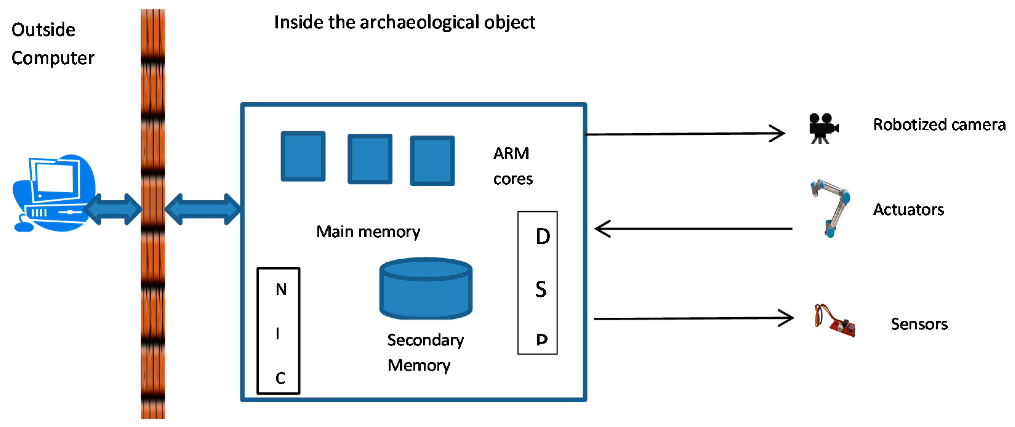
The system’s arms, sensors, manipulators, and other peripherals are controlled by an embedded system with a multi-core system on a chip, analog-to-digital converters, digital signal processors, shared main memory, non-volatile secondary memory, and a network card. Depending on the configuration of the internal portion of the battery station and the mobility of the observational platform, the network card might need to be wireless. The internal platform is connected to the external computer, shielded from electromagnetic interference and environmental exposure, which, in turn, is connected to the Internet through a wired, optical, WiFi, mobile, or satellite link (e.g., Iridium, Inmarsat), depending on the remoteness of the tomb.
Figure 1 is a diagram of the overall hardware architecture of the system.
2.2. Software Configuration
The embedded system runs an embedded operating system. Because of the large number of robotic components, and especially if the platform itself is mobile, the Robot Operating System (ROS) might be the best choice. The latter should support all robotic component drivers, dynamic load-balancing for the rover or walker, path navigation, obstacle avoidance, battery management, and various other constrained mobility requirements specific to the tomb. It should also support the camera array, especially with camera-calibration procedures, volumetric modeling, and proper positioning to reduce distortion and occlusion during composite imaging. Finally, it should support the full range of artifact manipulation, examination, study, and preservation.
The software configuration also supports a live network connection for reception of commands and instructions and the uploading of data, long-term storage of accumulated data in case of network connectivity loss, remote testing, verification, rebooting, updating (of ROS and software components), and other control procedures.
3. Generating of Global Identifiers of the Artifacts
Each datum in our non-destructive methodology must be uniquely identified in space and time for worldwide distribution. We have devised a method which generates each key by cryptographic hashing based on the Advanced Encryption Standard (AES)—Rijndael [
3]. We use double AES hashing, ensuring that no two scientific facts will be assigned the same key regardless of location or time. The method is described in [
4] where the latest development results are presented. Here we briefly review the main phases of the key generation.
The method starts with some scientist-assigned visible name which is padded with extra bits to a chosen key length of 256 bits. AES cryptographic hashing is applied to the padded string using cipher-block chaining but discarding intermediate cipher text blocks. In the initial step the padded visible name serves as the cipher key used to encrypt a known text pattern, which is chosen to be all 0 s. This yields a one-way function of the cipher key. The last cipher text block is the hash value.
The next phase is to achieve absolute theoretical and practical uniqueness. A randomization function applied to the visible name generates a string with very high degree of randomness. The function combines static and dynamic attributes to produce unique values. The static attributes are selected from a snapshot of certain system parameters at the time of the first call of the randomizing function, while the dynamic ones change every time the function is called. The resulting random string is input to the AES hash function using the hash value obtained in the first phase. This time the cypher text block produced by the last step is the unique datum key.
Using the theoretical analysis in [
5] we estimated the collision degree, which depends on the Hamming distance between the randomized strings. If the same visible name is used as input, the collision degree is slightly more than 1 out of 2
256 generated keys, which is enough reason to consider the generated keys geographically and temporally unique. At the implementation level, we ran the key generation with the same two-letter visible name 30 million times and there were no duplicate keys.
4. Common Method for Key-Value Data Modeling and Geometric Modeling
Octree data structures are very well suited for modeling in 3D-space and so octree modeling is a popular technology in design and manufacturing [
6,
7]. We have used octrees for several projects (e.g., airport grounds and runway modeling) prior to the non-destructive archaeology and accumulated significant codebase and experience. This section describes our use of octree modeling for both the spatial modeling of the archaeological sites and artifacts and for creating a global key space for the archaeological data. The integration of the abstract key-value space and the physical space of the objects of interest has led to a natural overall octree model for the non-destructive archaeology domain.
4.1. Octree Modeling
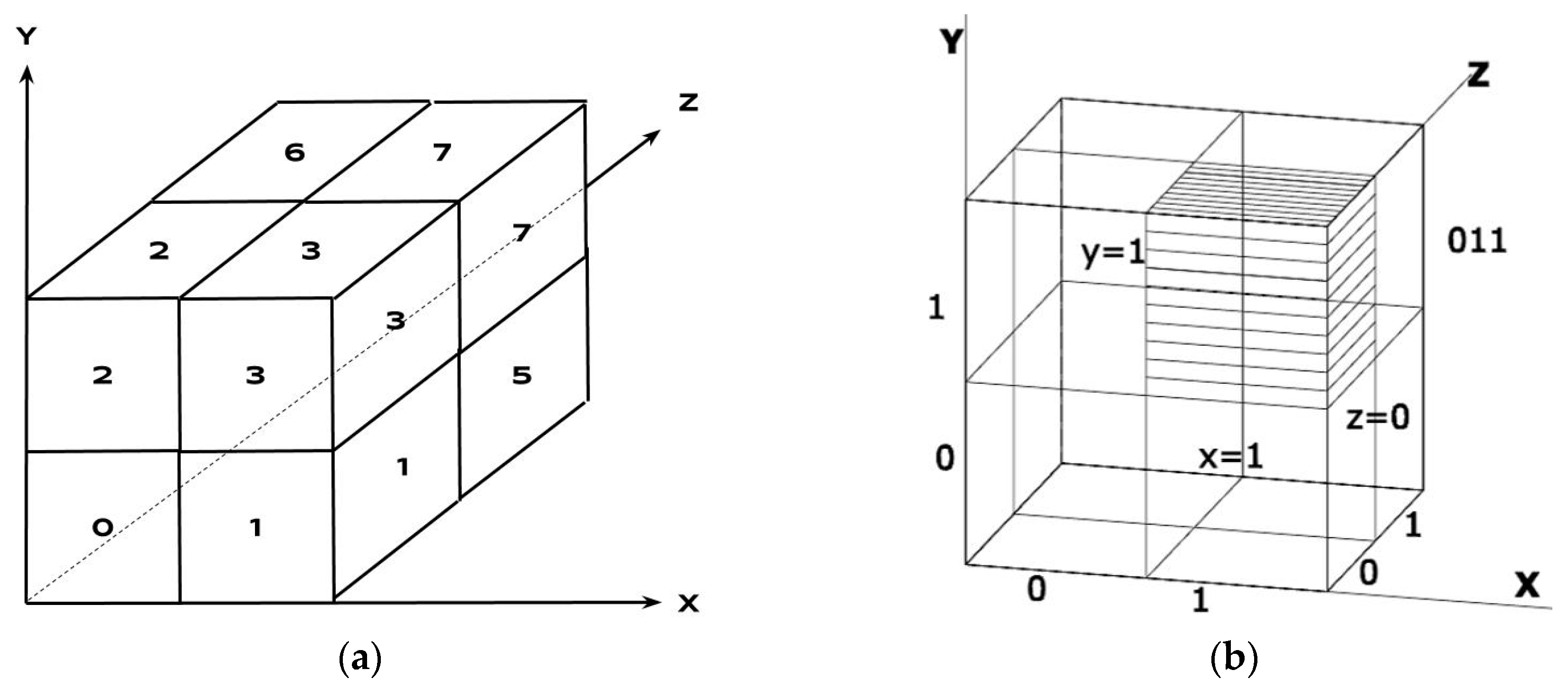
Octrees represent three-dimensional cubes divided into a hierarchy of spatial grids. The top-level grid (aka level-1 grid) splits the cube into eight sub-cubes called octants. Every octant (parent) is further subdivided into eight children, recursively forming a tree. Every octant has an index in its parent cube, which is an ordered triple of its displacement (
0 or
1) from the
ZYX origin of the parent (
Figure 2). The highlighted octant has displacement of
1 in the
X dimension,
1 in the
Y dimension, and
0 in
Z dimension, so its binary index is
0112 =
310.Following such numbering, every octant has a unique identifier that is a vector of triples. A triple represents the cubes from all levels to which a given octant belongs. For example, if the modelling resolution has 5 levels, the identifier has 5 binary triples:
| Level 5 | Level 4 | Level 3 | Level 2 | Level 1 |
| 001 | 101 | 111 | 100 | 011 |
The identifier 001 101 111 100 011, read from right to left, represents an octant that is a part of cube 3 on level 1, cube 4 on level 2, cube 7 on level 3, cube 5 on level 4, and is itself cube 1 on level 5. The octant identifiers have variable size that depends on the octree depth (chosen precision) at each leaf. For example, the identifier 100 111 presents the 4-th child of the 7-th top-level parent.
4.2. Octree Key-Value Data Modeling
We use an octree to represent a data space with hypercube topology. Each datum is a key-value pair. Keys are interpreted as direct octree node address. The entire key space can be covered by straightforward octree traversal. A hypercube with 256-bit keys provides a global virtual address space for the non-destructive archaeology domain.
The values in the key-value pairs are scientific data or data references. The type and interpretation of a value depends on the archaeological application. Values are usually stored in the leaf nodes of the octree. However, this results in an extremely sparse tree where intermediate nodes are only used as paths to the leaves. We avoid such emptiness by implementing a simple feature allowing us to store data in the intermediate nodes as well. We use keys with leading zeros (e.g., 000) as keys to intermediate node by simply truncating the leading zeros. For example, a key 000 … 000 100 001 is not considered a leaf key, but the key for the 4-th node on level 2, whose parent is the 1-st node on level 1.
The key with all 0s (000 ... 000) is the key for the root of the tree, where the value contains profile information for the archaeological application (description, funding, scientist names, IP address, etc.). Due to the global uniqueness of the keys, any two partial octrees are non-overlapping and can be merged by straightforward mapping in the global address space. This allows a virtually infinite number of separate archaeological projects to use the global space by simply being assigned a unique sub-tree root key. The inherent sparseness of the full theoretical address space of 2256 key-value pairs makes its reification both unfeasible and unnecessary. Our approach uses the benefits of the abstract octree key space (global uniqueness, straightforward merging, etc.), but our implementation uses conventional lookup tables to access the nodes. Each archaeology team can use the collections support of the own choice of programming to manipulate their sub-space.
4.3. Clustering Algorithm
Scientific results and artefacts are highly interconnected. A researcher often needs to retrieve all objects related to a given object, at once. We have implemented fast retrieval for objects clustered in the octree sub-space, where a cluster is a linked list of object nodes.
Our algorithm for clustering (partly based on our previous work [
8]) calculates the relative interconnectivity of the data objects (values) in the nodes. The connections (references) between data objects are represented as a list, containing n-tuples of connected data objects (nodes). The first array member is some name of a reference (connection). The next members are the identifiers (unique keys) of the connected nodes. The more references a node has to others and is referenced from others, the higher its interconnectivity.
Several analytical representations of interconnectivity could be found as criteria for data clustering. Our approach is based on the calculation of the weight
Wj of each tuple
j, represented as a reciprocal value of the number of keys in the tuple. For example, if tuple
j contains three keys, its weight will be:
Wj = 1/
Nj = 1/3, where
Nj is the number of members in the tuple
j. Correspondingly, the interconnectivity
IC(Xi) is calculated by adding the weights of the references, in which the key participates. Then, the interconnectivity coefficient of a node
i is the sum of the tuple weights, where the key of the node participates:
where
Wji is the weight of the tuple I, in which the key
i participates, and
M is the number of references (connections) of the key
i.
Without increasing the complexity, we use the next formula for the interconnectivity of data object
Xi:
where
Xi signifies key
i,
M is the number of the references from key
i,
Nj is the number of members in a tuple
j, where
i participates,
P is the number of all tuples, and
Kj is a regulatory coefficient for heuristic parameterization of the node interconnectivity according to other criteria, allowing tuning of this formula on a node-by-node basis.
The denominator sum can be pre-computed and is a normalization factor. Such an approach has two objectives. First, only integer arithmetic is used, which keeps the algorithm fast. Second, it significantly simplifies the insertion of some regulatory coefficients Kj. Different normalization could be used, for example, the sum of max and min interconnectivity.
The kernel of the separate clusters could be selected by the scientists manually according to different preferences. However, here we propose automatic selection based again on the relative interconnectivity. The main principle of kernels selection is to have minimal relative interconnectivity between kernels. The first kernel will be the node with the greatest IC(Xi). After that, the relative interconnectivity (RIC) of all other nodes with the first kernel is calculated. The second kernel chosen will be the node with minimal RIC with the first kernel and maximal interconnectivity among all currently non-clustered nodes.
Again, the relative interconnection is calculated regarding selected kernels and all other nodes in order to choose the next kernel. This is repeated until some pre-defined number of kernels is reached.
The node with greatest relative interconnectivity with some cluster is partitioned to this cluster. During the same step, some objects are assigned to every other cluster. After that, all RIC are recalculated and again a node is partitioned to every cluster. This procedure can be repeated to some degree of clustering.
More precise clustering could be achieved by calculating two relative interconnectivities for every non-assigned node:
First, the interconnectivity value to the nodes in cluster i;
Second, the interconnectivity value to the nodes in all other clusters except the considered cluster i.
The node with the lowest RIC, calculated by the second rule, is assigned to cluster i. If the calculated RIC by the second rule is the same for several nodes, the selection is made according to the maximum RIC calculated by the first rule. After every selection of a node, the RIC coefficients should be calculated again. This loop continues until clustering completion.
4.4. Octree Geometrical Modelling
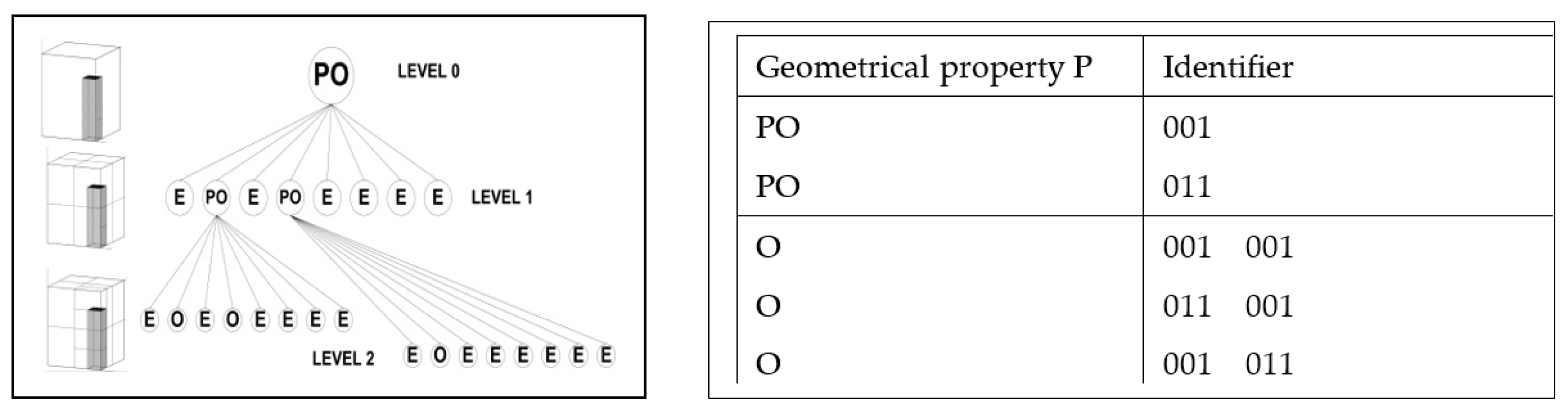
We use octree spatial occupancy enumeration as a basis for the formal representation of three-dimensional (3D) for (approximate) modelling of site volumes and artefacts in the physical space. Every 3D object is defined fully in the modelling cube. Its description is a family of k + 1 ordered pairs {P, Ei}, where 0 ≤ i ≤ k (k is the maximum octree depth), P is a finite set of properties, and Ei is the set of the octants (E0 represents the outermost modelling cube). The properties P characterize the modelled object and can be geometrical, physical, or any other kind. The octant occupancy parameter value set is {Empty (E), Partly Occupied (PO), Fully Occupied (O)}. The octants in Ei are octree nodes with the following characteristics:
the root of the octree is on level 0 and represents the whole modelling cube;
all other nodes can have 8 children which are an ordered sequence indexed from 0 to 7;
the edges of the tree denote a parent–child relationship;
every octant has only one edge to its parent;
all nodes with the occupancy parameter Empty or Fully Occupied are leaves of the tree;
all nodes with occupancy parameter Partly Occupied are internal nodes and have 8 children.
Figure 3 illustrates an octree for the spatial approximation of a simple 3D object up to level 2. More levels can be added for more precise (granular) approximation.
The octree implementation requires fast algorithms for manipulation of the tree, calculations of distances, and recognition of surfaces. The basic data structure for these algorithms is a matrix of octant identifiers and properties. If there is only one identifier in a matrix row, it represents an octant on level 1, if there are two identifiers the octant is from level 2, and so on. The empty octants are not presented in the matrix. Distances are calculated using integer arithmetic without multiplication or division. The matrix for the octree in
Figure 3 is given in the table to the right.
Every octant has an origin point that is x = 0, y = 0, z = 0 in the octant’s local coordinate system. Only the origin point of the modelling cube (the root) has world coordinates. For all geometrical calculations in the octree, we need the world coordinates of the origin point and the length of the side of the outermost cube.
5. XML Distribution of Archaeological Information
5.1. Core XML Vocabulary
XML provides a tree-like data structure and search ability for global data distribution that allows different teams to retrieve and maintain sub-trees according to different interests and application goals. Archaeological information is both various and dynamic. Over time, the data for a single object accumulates continuously with new reports, carbon dating, laboratory analyses, and geophysical measurements.
The embedded system formats the data it collects as XML documents in a XML steam, which are easy to parse, validate, and transform into various end-user formats. By filtering the markup, the software client of different archaeological teams or even individual team members can access only the data of interest, sliced along physical, temporal, and abstract informational dimensions. For example, a sedimentological specialist may retrieve and extract only the sub-trees that deal with specific soil probes and analyses by colleagues.
Our design decision to generate and distribute non-destructive archaeology data as XML documents is motivated by several considerations:
analysis of the discussion on structuring XML for archaeological surveys and reports contained in [
1,
9];
emerging consensus from private consultations with domain experts on the infeasibility of creating and maintaining a universal archaeological XML vocabulary, and strong preference for largely independent XML vocabularies per site, team, and research goal;
recurrent difficulty in distinguishing original archaeological data from (sometimes commercially manipulated) interpretive analysis;
strong criticism of the practise of publishing only interpreted data as the sole format of dissemination of archaeological knowledge.
These factors boiled down to two concrete requirements for our XML documents:
a basic schema consists of a minimal core XML vocabulary open to the community for iteration and extension through specialized in-depth vocabularies;
each embedded system disseminates only original data in the XML core vocabulary while different teams attach their own research, analysis, interpretations, and conclusions.
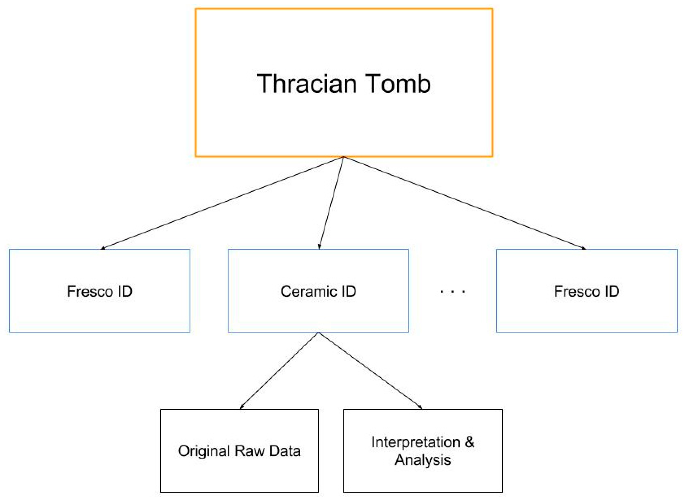
The XML core vocabulary (
Figure 4) has a root that describes the data of the whole site (buried church, tomb, or other). The children of the root (first-level nodes of the XML tree) are the discovered artefacts or other important materials.
Every first-level node has a name and a globally unique identifier. It contains a description and references. Every first-level node has two children:
Data, which is a collection of the primary original information that is selected by the embedded system (images, probes, etc.).
Interpretation, which could be a subtree containing the results of the archaeological research. Every interpretation subtree can be written in some specific XML vocabulary.
The markup of the tree presented on the figure is the following:
- ■
<Thracian Tomb>
- ■
<Fresco ID1>
- ■
<Data> …
- ■
</Data>
- ■
<Interpretation> …
- ■
</Interpretation>
- ■
</Fresco ID1>
- ■
<Ceramic IDx>
- ■
<Data> …
- ■
</Data>
- ■
<Interpretation>….
- ■
</Interpretation>
- ■
</Ceramic IDx>
- ■
…….
- ■
</Thracian Tomb>
5.2. XML Streaming
Our research proposes an abstract view of archaeological data and their interpretation as an XML stream. Different Web applications use policies to extract from the stream the information that they need. Archaeological XML documents are distributed openly throughout the archaeological community but they are consumed primarily by those teams and individuals who are researching a site under real-time observation by an embedded system. Subscription models and access policies may be put in place depending on the funding and authority of the observed site.
We model the set of archaeological documents as an abstract XML stream. The stream provides access control and references a document database. Metadata fully annotate the data contents of each part of the stream, including access rights and encryption status. Some XML documents may be individually encrypted. Every client application can use web services to get the stream but can decrypt only the parts that are accessible to an assigned role (archaeologists, museum administrator, etc.). After authentication and proof of permissions, the client opens the metadata and makes available the needed versions of the required documents. The client has continuous open access for the duration of the session.
The stream model provides three system-architectural advantages. First, since the stream exists independently from the local archaeologist’s systems, it facilitates the storage and processing requirements on them. Second, since the stream contains the minimum sufficient data and control for every role in the research group, it enables complete modularization and distribution of the provided services. Third, based on the above two requirements mentioned in the previous section, it allows the continuous in-vivo evolution of the research process and eliminates step-wise system upgrades.
5.3. Replication with Local Databases
Access control to the information in the XML stream must provide availability and security.
Availability for every scientist is organized by a standard username-password pair and access rights. Every scientist can read all the information of interest. The scope of the reading access is only restricted by a policy that depends on a special interest group. The scientists make Web service request to the local server and receive the stream. The stream is converted to XML text and further to a Document Object Modelling (DOM) tree that could be stored in the local database. The theoretical foundations of such conversion, validation, and streaming of XML documents can be found in [
10]. It is implemented in XML repositories and retrieval methods, and is supported by most development environments [
11].
Writing access can be given to anyone in a special interest group but only to the interpretation section of the XML stream. The data generated by the embedded system is read-only and cannot be changed. We have successfully experimented with the editing policy of Wikipedia.
The abstract data stream is designed to minimize technical constraints. The success of the non-destructive archaeology methodology which adopts it for data distribution depends to a high degree on the quality design of the specific archaeological XML vocabularies for the interpretation subtrees and the sensibility of the access policies.
6. Increasing the Fault Tolerance of the System
Our non-destructive archaeology methodology puts a high demand on the fault tolerance and reliability of the embedded system sealed within a site. The system must be dry-run tested before installation until the initial error burst finishes and the system reaches steady-state error density. After installation, the system performs periodic tests, error analysis, and monitoring to maintain this density.
Our test suite, though based on traditional methods, has refined error models and increased diversity. A good error model must be simple and represent a high percentage of system defects. Our error models cover (a) systematic and intermittent hardware (cores and memory) errors; (b) software errors (bugs); and (c) parametric errors (e.g., out-of-range data from a sensor or actuator). An error model divides the set of all possible errors into covered errors, that is, errors represented by the model, and non-covered errors, that is, errors that the model is too simple to represent. For example, a simple error model for digital logic covers only the following error cases: stuck-at-0, stuck-at-1, and bridge; all other errors are non-covered.
For non-covered error in such noisy environment we strongly rely on the software for error-correcting codes, which is plugged-in the operating system.
6.1. Hardware Testing
The hardware tests are mostly standard so we just enumerate them.
The processor test consists of a functional test for every ARM core and a test of core interconnects. The core test generates stimulus test patterns. An in-circuit emulator runs in the core and the responses are compared with the expected values. The core test also includes boundary-scan testing.
The main memory is tested by dynamic test sequences like running 0-and-1, galloping 0-and-1, chess, ping-pong, etc.
The hard disk periodically runs a degradation test for some of tracks and performs a runtime procedure to replace bad track with reserve ones.
6.2. Software Testing by Signatures
Analysis with signatures is used for dynamic hardware testing, message integrity in computer security, virus discovery, and software testing.
Software is treated as a binary data sequence. A prototype software digest (signature) is calculated and stored as a reference. Periodically, the software signature is calculated and compared to the prototype. If they are not equal, software integrity has been violated by a software bug, data degradation, or tampering. We use AES cryptographic hashing to calculate the signature.
Signature testing can also check runtime instruction flow although the implementation is difficult and the overhead significant. We have limited our use of signature testing only to those parts of the system software where non-covered errors are most likely, such as the routines that handle sensors and actuators. We have implemented two simple approaches.
A signature test monitors whether each tested routine has been modified since it was loaded and initialized.
Background routines periodically execute the functions of each sensor or actuator interface and record the data. A signature is calculated for the data and compared its prototype signature.
6.3. Micro-Rebooting for Software Recovery
In most embedded systems, the non-covered errors are difficult to define, discover, and reproduce. They are often nondeterministic and are triggered by the noisy environment and unpredictable behaviour of the sensors and actuators. In isolated systems, the only way to recover from a non-covered error is by rebooting. Rebooting clears accumulated deadlocks, releases blocked threads, and returns the system to a stable ready state. For example, satellites are such isolated systems and their necessary high error tolerance is often achieved by periodic rebooting, either of the whole system, or of independent subsystems.
Rebootability is not supported in modern general-purpose operating systems, runtime environments, or commercial systems due to their high level of abstraction with respect to the underlying hardware. For this reason, we have had to provide our own. We have achieved partial rebootability by utilizing specific features of the Java development environment, applying them only to the user threads that manipulate the external devices. Our design follows best practices in the design of mission-critical embedded systems.
User threads are functionally loosely connected. They run independently and perform inter-thread communications by non-blocking mechanisms. One thread cannot call another. If the service from a thread is not available, the client thread must either wait or restart the communication. Such an approach is implemented in Java, where the threads can send a signal (known as thread interrupt) to another thread inviting, but not forcing, it to do something.
When some unusual conditions occur, loose (coarse) monitoring of each individual thread takes place and prompts restarts.
Threads that work with sensors and actuators implement an interface that allows rebooting of the external devices into a well-known state. The interfaces implement the policy that a thread is unavailable unless it replies gracefully.
Exceptions are always processed, never ignored. Sophisticated exception handling and logging happens in custom handler blocks at the highest level of the caller hierarchy. Handlers analyse each exception and, depending on the severity of the error, may cause the system to ignore it or reboot. This simplifies the design and implementation of the system the same way an event-driven system does not have implement polling and preemptive intervention.
6.4. Checking Data Ranges
The sensor and actuator control algorithms must monitor the readings from external devices and maintain their operation within defined ranges. We use an approach utilizing two algorithms with different resolution, in which the coarse algorithm defines a range in which the fine algorithm result should fall. If the fine-control algorithm shows an out-of-range reading, the system invokes a coarse-control routine to reproduce the erroneous result in a higher-tolerance range. If the data are both in the larger range, a recalibration procedure is initialized. If the data are not in the same range, a reboot takes place.
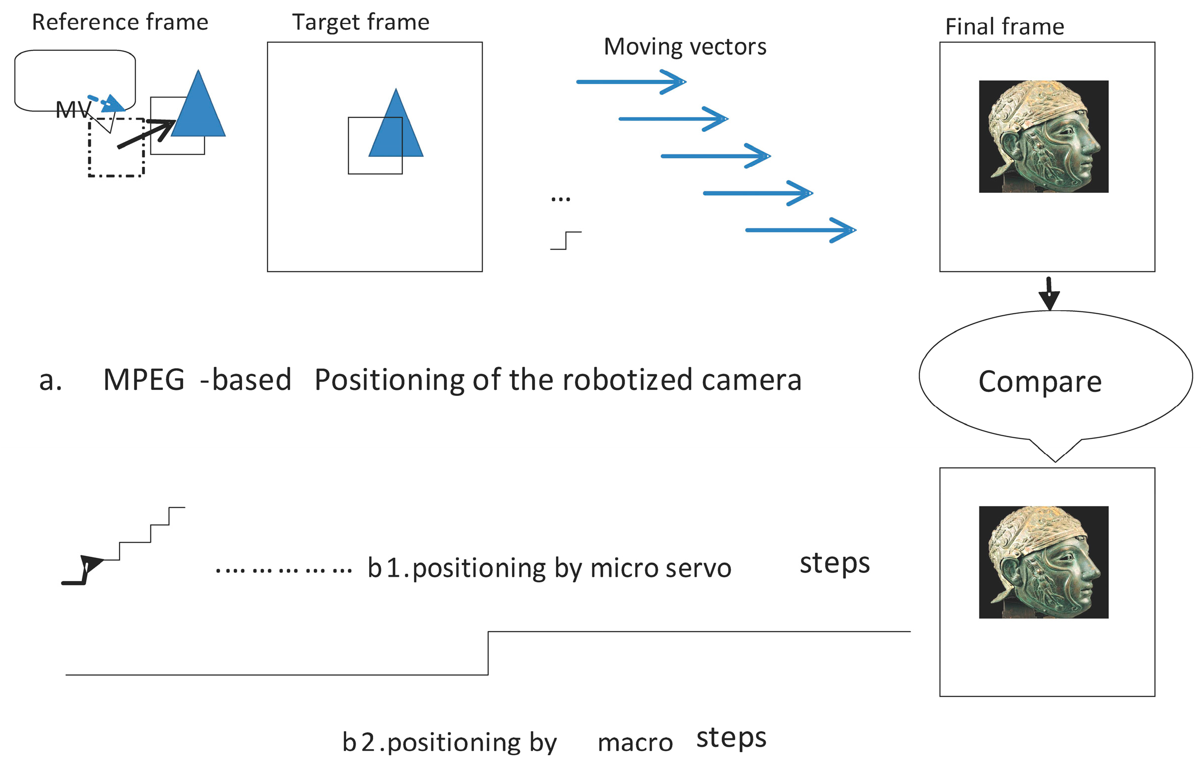
The robotized camera and sensor assembly is the most critical peripheral device of the non-destructive archaeology system. Here we illustrate our approach in testing the positioning of the camera. The embedded system receives an external request for an image of some artefact. The request carries the identifier (key) of the artefact, which the system uses to consult the geometrical model and generate the necessary instructions to the positioning circuitry of the camera. We use two algorithms in parallel for range testing of the positioning software and circuitry: one based on control theory and the other on image processing.
Figure 5 is an illustration of both approaches.
The first algorithm generates the movement of the assembly as a sequence of (∆x, ∆y, ∆z) micro-servo control steps causing the camera to locate the artefact. As discussed above, we use a fine and course algorithm component.
The second algorithm emulates Moving Pictures Expert Group (MPEG) video processing, which is part of the embedded system software. MPEG video compression calculates the difference between frames in the camera motion. It employs motion compensation to estimate the motion vector and predict the motion. Each image of the artefact is divided into macroblocks. The current image is the target frame. The future or previous frame is the reference frame. Macroblocks from both target and reference frames are compared pixel-by-pixel. The offset of the reference macroblock to the target macroblock is the motion vector. The difference between the pixel values of both macroblocks is the motion prediction, which is stored in the resulting frame (P or B frame).
6.5. Some Formalization
The probability
P(
F) for passing a test is calculated by the equation:
where
pj is the probability of covered error occurring,
mj is the probability the test will not detect the error,
pk is the probability of a no-covered error occurrence and
mk is the probability the test will not detect not-covered errors.
Mc is the number of covered errors; and
Mn is the number of no-covered defects.
For simplicity we consider hardware errors as covered errors, that means with some approximation qj = 0. For not-covered errors, qk can take value from 0.05 to 0.5.
The probability
pk could be extracted from the formula:
where
TestSuccess shows the percentage how many errors are detected, and
n is the number of possible errors. The number of uncovered errors depends on system configurations and the reliability of the external devices.
Without considering of the presented specific approaches, the number of uncovered errors (calculated by benchmark and expert estimation) is 450 per million possible errors. The
TestSuccess was 95%. Then
p = 1.14 × 10
−3, where
p =
pk is the probability of not covered errors. The probability
P(
F) that the system will pass a test is:
The formalization predicts that the error level would be about sixty errors per million. Performing the presented additional approaches, we could reduce the number of uncovered errors by 60%–70%, i.e., 15 per million. The effect by most of them could be recovered by rebooting.
7. Experimental Implementation Scenario
Our original motivation to develop the concept and methodology for non-destructive archaeology was two-fold. On one hand, we were appalled by the recent fate of several Thracian tombs, preserved intact for two millennia to the present day, only to be excavated with a bulldozer in a mad rush for first dibs and grievously damaged in the process. On the other, we wanted to bridge the efficiency gap in the current ad-hoc discovery process plagued by incompatible research styles and a whole host of indexing, recording, and documentation techniques varying from paper notebooks to smart phones. A hands-off methodology with unified data management and open dissemination evolved naturally. We briefly present our alternate scenario of non-destructive excavation and study of Thracian tombs in the Kazanlak Valley—aka Valley of the (Thracian) Kings—in present-day Bulgaria.
Using our system, we create a geometrical model, first of the entire valley, and then separately for each individual tomb. The model is based on the octree for spatial enumeration modelling.
We generate unique keys from the names given by archaeologists to every tomb and artefact thereof (frescos, ceramic pieces, antique jewellery, etc.), often including
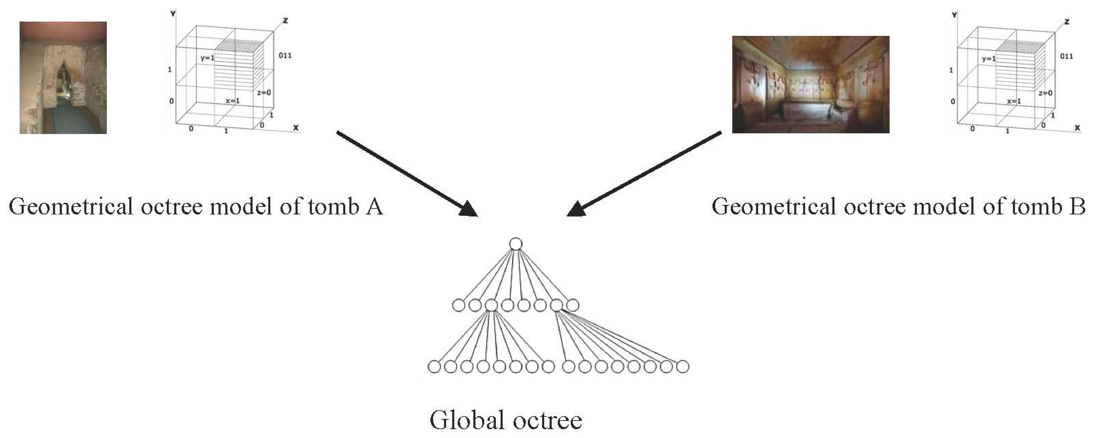
xyz coordinates for higher resolution. Each tomb and its attendant artefacts forms a sub-tree in the global key space. The randomization in our key-generation method prevents duplicates in the global key space despite duplicate names, and the sub-trees do not overlap in either physical coordinates or temporal relationships of archaeological projects. Sub-trees for different tombs can therefore be merged into the global octree without modification.
Figure 6 illustrates the process of merging the separate work of different archaeological teams into the common octree data structure.
In contrast to the tomb sub-trees, the global octree is not a geometrical (spatial) model but an abstract key space. The values in the global octree have two required fields: the given visible name of the object and the xyz coordinates in the geometrical model of its containing tomb. The rest of the information depends on the needs of the archaeologist and could be anything: a reference to a document, a catalogue number, textual description, field notes, a hypothesis, etc.
The 256-bit keys of the global data structure became a performance bottleneck. Using a 256-bit key for search is computationally expensive and unnecessary for the scope of our project. To overcome this problem, we came up with a 4-byte digest of the key we called search key. A 32-bit digest ensures fast lookup in any data structure that implements the octree topology. The search key was also generated by AES hashing. The search key, when used with 256-bit keys, is fully collision-free if the Hamming distance between the keys is 1, 2, or 3 bits. For 4 or more bits, we used the formula , where r is the distance in bits. On average, the collision degree is slightly above 1 in 232 generated search keys. The search tree is used as the input to a lookup table. The lookup result is a reference (pointer) to the value of the selected node.
8. Some Publications Which Have Influenced Our Work
The presented methods are a result of several years’ worth of relevant development experience. Here we review several milestone approaches of other authors that have influenced our implementation.
Key-value implementation. Our implementation of key-value lookup is based on a group of publications that have had a significant impact on fast and efficient network routing lookup. The method in [
12] provides scalable and fast lookup processing and is the foundation of our implementation. The approach in [
13] has influenced our plans for future work.
Octree modelling. The octree is a standard approach in 3D geometric modelling. The authors of [
14] describe well the spatial enumeration approach we have used for representation of solid objects in a 3D environment, while the authors of [
15] present a method for merging geometrical octrees in databases. In contrast, our method uses an octree as a global data structure model. Here we can mention [
16], where stratigraphic modelling of archaeological excavations is combined with octree decomposition.
Signature testing. The Hewlett Packard dynamic testing [
17] started a revolution in the usage of signatures. A great source for software analysis by signatures is presented by authors of [
18]. The patent shown in [
19] provides practical methods for testing software integrity and virus discovery.
Recovery by rebooting. Authors of [
20,
21] make a compelling case for the importance of rebooting in different modes operation.
Cultural heritage XML data sharing. Computer vision, networking, and multimedia technology have become popular approaches of exposing and exploring the history human civilization [
22]. In the literature there are many papers and projects that use XML to prepare archaeological digital documents for dissemination. Such publications are beyond the scope of this paper. As an example, we mention the Open Context project [
23] that discusses the problem of presenting the primary data using ArchaeoML. ArchaeoML can be used as a concrete vocabulary for building a subtree in our core XML.
9. Discussion
We have shared our concept for non-destructive archaeology in the form of a brief sketch of the overall system and in-depth research of several important software components. Our system sketch focuses on archaeological sites with restricted access—like buried or cave churches, tombs, and active religious shrines—but the methodology is equally well suited to archaeological and cultural sites in general. Our main goal has been to enable unconstrained sharing of results among archaeological teams within a common information space and the unrestricted worldwide distribution of the raw data, findings, records, analyses, hypotheses, and conclusions. Ideally, the archaeological record could be dynamically updated and re-evaluated with the latest discoveries and newest schools of thought.
In a series of publications, we have shared our development methods for creating a prototype of an embedded system for non-destructive archaeology. Some of the approaches are classical and based on our professional experience; others are new and are taken from proof-of-concept to reference implementation. In this paper, we have focused on the following contributions:
Our main achievement is that by prototyping the embedded system we have convinced some archaeological research teams that computer surveillance provides efficient non-destructive archaeology for a special type of sites like buried churches and tombs.
Use of an octree data structure to model a global key space is our original approach. Based on global identification, scientific results are presented in a global virtual data store. Every scientist can build their own local data structure and merge it with the results of others in the global store without naming and merge conflicts.
We have created a geometrical model of the archaeological object using octree spatial enumeration. The geometrical model provides a virtual hierarchical space for traversal referencing of archaeological discoveries.
The octree has allowed the elegant and seamless merging of the global abstract key-value space and the individual geometrical models of archaeological objects in physical space and time.
The embedded computer system generates an XML stream that is accessible to archaeologists worldwide. We offer a basic XML vocabulary with separate elements for original data and interpretations. For different discoveries, separate vocabulary extensions and sub-namespaces are created.
The fault tolerance of the system is improved by specific test methods: testing by signature, micro-rebooting of the software controlling sensors and actuators, and checking parameter data ranges by parallel algorithms.
We hope that with the continued advances in novel technologies like robotics, machine learning, autonomous vehicles, IoT, and solar energy, our non-destructive archaeological methodology can materialize into fully-autonomous robotic archaeological exploration, excavation, observation, modelling, and data dissemination.


