


Synthesis and Electrochemical Performance of Microporous Hollow Carbon from Milkweed Pappus as Cathode Material of Lithium–Sulfur Batteries
 ,
,
Abstract
:1. Introduction
2. Experimental Methods
2.1. Preparation of Milkweed Pappus Carbon (MPC)
2.2. Synthesis of Milkweed Pappus Carbon–Sulfur (MPC–S) Composites
2.3. Characterizations
2.4. Electrochemical Measurements
3. Results
4. Conclusions
Supplementary Materials
Author Contributions
Funding
Institutional Review Board Statement
Informed Consent Statement
Data Availability Statement
Conflicts of Interest
References
- Zhang, S.S. Liquid electrolyte lithium/sulfur battery: Fundamental chemistry, problems, and solutions. J. Power Sources 2013, 231, 153–162. [Google Scholar] [CrossRef]
- Mikhaylik, Y.V.; Akridge, J.R. Polysulfide Shuttle Study in the Li/S Battery System. J. Electrochem. Soc. 2004, 151, A1969–A1976. [Google Scholar] [CrossRef]
- Yang, Y.; Yu, G.; Cha, J.J.; Wu, H.; Vosgueritchian, M.; Yao, Y.; Bao, Z.; Cui, Y. Improving the Performance of Lithium–Sulfur Batteries by Conductive Polymer Coating. ACS Nano 2011, 5, 9187–9193. [Google Scholar] [CrossRef] [PubMed]
- Ji, X.; Lee, K.T.; Linda, F.N. A highly ordered nanostructured carbon–sulphur cathode for lithium–sulphur batteries. Nat. Mater. 2009, 8, 500–506. [Google Scholar] [CrossRef] [PubMed]
- Liu, Y.; Zhan, H.; Zhou, Y. Investigation of S/C composite synthesized by solvent exchange method. Electrochim. Acta 2012, 70, 241–247. [Google Scholar] [CrossRef]
- Li, K.; Wang, B.; Su, D.; Park, J.; Ahn, H.; Wang, G. Enhance electrochemical performance of lithium sulfur battery through a solution-based processing technique. J. Power Sources 2012, 202, 389–393. [Google Scholar] [CrossRef]
- Lai, C.; Gao, X.P.; Zhang, B.; Yan, T.Y.; Zhou, Z. Synthesis and Electrochemical Performance of Sulfur/Highly Porous Carbon Composites. J. Phys. Chem. C 2009, 113, 4712–4716. [Google Scholar] [CrossRef]
- Chen, S.-R.; Zhai, Y.-P.; Xu, G.-L.; Jiang, Y.-X.; Zhao, D.-Y.; Li, J.-T.; Huang, L.; Sun, S.-G. Ordered mesoporous carbon/sulfur nanocomposite of high performances as cathode for lithium–sulfur battery. Electrochim. Acta 2011, 56, 9549–9555. [Google Scholar] [CrossRef]
- Choi, Y.-J.; Kim, K.-W.; Ahn, H.-J.; Ahn, J.-H. Improvement of cycle property of sulfur electrode for lithium/sulfur battery. J. Alloy. Compd. 2008, 449, 313–316. [Google Scholar] [CrossRef]
- Rao, M.M.; Song, Y.X.; Cairns, E.J. Nano-carbon/sulfur composite cathode materials with carbon nanofiber as electrical conductor for advanced secondary lithium/sulfur cells. J. Power Sources 2012, 205, 474–478. [Google Scholar] [CrossRef]
- Zheng, M.; Chi, Y.; Hu, Q.; Tang, H.; Jiang, X.; Zhang, L.; Zhang, S.; Pang, H.; Xu, Q. Carbon nanotube-based materials for lithium–sulfur batteries. J. Mater. Chem. A 2019, 7, 17204. [Google Scholar] [CrossRef]
- Guo, J.; Xu, Y.; Wang, C. Sulfur-Impregnated Disordered Carbon Nanotubes Cathode for Lithium–Sulfur Batteries. Nano Lett. 2011, 11, 4288–4294. [Google Scholar] [CrossRef] [PubMed]
- Ahn, W.; Kim, K.-B.; Jung, K.-N.; Shin, K.-H.; Jin, C.-S. Synthesis and electrochemical properties of a sulfur-multi walled carbon nanotubes composite as a cathode material for lithium sulfur batteries. J. Power Sources 2012, 202, 394–399. [Google Scholar] [CrossRef]
- Wang, H.; Yang, Y.; Liang, Y.; Robinson, J.T.; Li, Y.; Jackson, A.; Cui, Y.; Dai, H. Graphene-Wrapped Sulfur Particles as a Rechargeable Lithium–Sulfur Battery Cathode Material with High Capacity and Cycling Stability. Nano Lett. 2011, 11, 2644–2647. [Google Scholar] [CrossRef] [PubMed] [Green Version]
- Park, M.-S.; Yu, J.-S.; Kim, K.J.; Jeong, G.; Kim, J.-H.; Jo, Y.-N.; Hwang, U.; Kang, S.; Woo, T.; Kim, Y.-J. One-step synthesis of a sulfur-impregnated graphene cathode for lithium–sulfur batteries. Phys. Chem. Chem. Phys. 2012, 14, 6796–6804. [Google Scholar] [CrossRef]
- Cao, Y.; Li, X.; Aksay, I.A.; Lemmon, J.; Nie, Z.; Yang, Z.; Liu, J. Sandwich-type functionalized graphene sheet-sulfur nanocomposite for rechargeable lithium batteries. Phys. Chem. Chem. Phys. 2011, 13, 7660–7665. [Google Scholar] [CrossRef]
- Ji, L.; Rao, M.; Zheng, H.; Zhang, L.; Li, Y.; Duan, W.; Guo, J.; Cairns, E.J.; Zhang, Y. Graphene Oxide as a Sulfur Immobilizer in High Performance Lithium/Sulfur Cells. J. Am. Chem. Soc. 2011, 133, 18522–18525. [Google Scholar] [CrossRef]
- Li, N.; Zheng, M.; Lu, H.; Hu, Z.; Shen, C.; Chang, X.; Ji, G.; Cao, J.; Shi, Y. High-rate lithium–sulfur batteries promoted by reduced graphene oxide coating. Chem. Commun. 2012, 48, 4106–4108. [Google Scholar] [CrossRef]
- Zhang, L.; Wang, Y.; Peng, B.; Yu, W.; Wang, H.; Wang, T.; Deng, B.; Chai, L.; Zhang, K.; Wang, J. Preparation of a macroscopic, robust carbon-fiber monolith from filamentous fungi and its application in Li–S batteries. Green Chem. 2014, 16, 3926–3934. [Google Scholar] [CrossRef]
- Chung, S.-H.; Manthiram, A. Carbonized Eggshell Membrane as a Natural Polysulfide Reservoir for Highly Reversible Li-S Batteries. Adv. Mater. 2013, 26, 1360–1365. [Google Scholar] [CrossRef] [PubMed]
- Chung, S.-H.; Manthiram, A. A Natural Carbonized Leaf as Polysulfide Diffusion Inhibitor for High-Performance Lithium-Sulfur Battery Cells. ChemSusChem 2014, 7, 1655–1661. [Google Scholar] [CrossRef] [PubMed]
- Wang, Z.; Shen, D.; Wu, C.; Gu, S. State-of-the-art on the production and application of carbon nanomaterials from biomass. Green Chem. 2018, 20, 5031–5057. [Google Scholar] [CrossRef] [Green Version]
- Powell, M.D.; LaCoste, J.D.; Fetrow, C.J.; Fei, L.; Wei, S. Bio-derived nanomaterials for energy storage and conversion. Nano Sel. 2021, 2, 1682–1706. [Google Scholar] [CrossRef]
- Zhang, Y.; Gao, Z.; Song, N.; Li, X. High-performance supercapacitors and batteries derived from activated banana-peel with porous structures. Electrochim. Acta 2016, 222, 1257–1266. [Google Scholar] [CrossRef] [Green Version]
- Li, Y.; Wang, L.; Gao, B.; Li, X.; Cai, Q.; Li, Q.; Peng, X.; Huo, K.; Chu, P.K. Hierarchical Porous Carbon Materials Derived from Self-Template Bamboo Leaves for Lithium–Sulfur Batteries. Electrochim. Acta 2017, 229, 352–360. [Google Scholar] [CrossRef]
- Ren, G.; Li, S.; Fan, Z.-X.; Warzywoda, J.; Fan, Z. Soybean-derived hierarchical porous carbon with large sulfur loading and sulfur content for high-performance lithium–sulfur batteries. J. Mater. Chem. A 2016, 4, 16507–16515. [Google Scholar] [CrossRef] [Green Version]
- Geng, Z.; Xiao, Q.; Wang, D.; Yi, G.; Xu, Z.; Li, B.; Zhang, C. Improved Electrochemical Performance of Biomass-Derived Nanoporous Carbon/Sulfur Composites Cathode for Lithium-Sulfur Batteries by Nitrogen Doping. Electrochim. Acta 2016, 202, 131–139. [Google Scholar] [CrossRef]
- Zhang, J.; Xiang, J.; Dong, Z.; Liu, Y.; Wu, Y.; Xu, C.; Du, G. Biomass derived activated carbon with 3D connected architecture for rechargeable lithium−sulfur batteries. Electrochim. Acta 2014, 116, 146–151. [Google Scholar] [CrossRef]
- Lu, S.; Chen, Y.; Zhou, J.; Wang, Z.; Wu, X.; Gu, J.; Zhang, X.; Pang, A.; Jiao, Z.; Jiang, L. A Sheet-like Carbon Matrix Hosted Sulfur as Cathode for High-performance Lithium-Sulfur Batteries. Sci. Rep. 2016, 6, 20445. [Google Scholar] [CrossRef] [PubMed] [Green Version]
- Zhang, Y.; Zhao, Y.; Konarov, A.; Li, Z.; Chen, P. Effect of mesoporous carbon microtube prepared by carbonizing the poplar catkin on sulfur cathode performance in Li/S batteries. J. Alloy. Compd. 2015, 619, 298–302. [Google Scholar] [CrossRef]
- Tao, X.; Zhang, J.; Xia, Y.; Huang, H.; Du, J.; Xiao, H.; Zhang, W.; Gan, Y. Bio-inspired fabrication of carbon nanotiles for high performance cathode of Li–S batteries. J. Mater. Chem. A 2014, 2, 2290–2296. [Google Scholar] [CrossRef]
- Lionetto, F.; Bagheri, S.; Mele, C. Sustainable Materials from Fish Industry Waste for Electrochemical Energy Systems. Energies 2021, 14, 7928. [Google Scholar] [CrossRef]
- Choi, Y.; Lee, S.Y.; Bae, J.S.; Lee, S.J.; Kim, H.K.; Jeong, E.D.; Shin, H.C. Nitrogen and Sulfur Co-Doped Porous Carbon Derived from Thiourea and Calcium Citrate for Lithium-Sulfur Batteries. Appl. Sci. 2020, 10, 1263. [Google Scholar] [CrossRef] [Green Version]
- Lee, S.-Y.; Choi, Y.; Kim, J.-K.; Lee, S.-J.; Bae, J.S.; Jeong, E.D. Biomass-garlic-peel-derived porous carbon framework as a sulfur host for lithium-sulfur batteries. J. Ind. Eng. Chem. 2021, 94, 272–281. [Google Scholar] [CrossRef]
- Rengasamy, R.S.; Das, D.; Karan, P. Study of oil sorption behavior of filled and structured fiber assemblies made from polypropylene, kapok and milkweed fibers. J. Hazard. Mater. 2011, 186, 526–532. [Google Scholar] [CrossRef] [PubMed]
- Liang, C.; Bao, J.; Li, C.; Huang, H.; Chen, C.; Lou, Y.; Lu, H.; Lin, H.; Shi, Z.; Feng, S. One-dimensional hierarchically porous carbon from biomass with high capacitance as supercapacitor materials. Microporous Mesoporous Mater. 2017, 251, 77–82. [Google Scholar] [CrossRef]
- Xu, B.; Hou, S.; Chu, M.; Cao, G.; Yang, Y. An activation-free method for preparing microporous carbon by the pyrolysis of poly(vinylidene fluoride). Carbon 2010, 48, 2812–2814. [Google Scholar] [CrossRef]
- Manthiram, A.; Fu, Y.; Chung, S.H.; Zu, C.; Su, Y.S. Rechargeable lithium–sulfur batteries. Chem. Rev. 2014, 114, 11751–11787. [Google Scholar] [CrossRef] [PubMed]
- Yin, Y.X.; Xin, S.; Guo, Y.G.; Wan, L.J. Lithium–sulfur batteries: Electrochemistry, materials, and prospects. Angew. Chem. Int. Ed. 2013, 52, 13186–13200. [Google Scholar] [CrossRef] [PubMed]
- Zhou, L.; Zhang, T.; Tao, Z.; Chen, J. Ni nanoparticles supported on carbon as efficient catalysts for the hydrolysis of ammonia borane. Nano Res. 2014, 7, 774–781. [Google Scholar] [CrossRef]
- Ma, F.; Wan, J.; Wu, G.; Zhao, H. Highly porous carbon microflakes derived from catkins for high-performance supercapacitors. RSC Adv. 2015, 5, 44416–44422. [Google Scholar] [CrossRef]
- Zhou, G.; Yin, L.-C.; Wang, D.-W.; Li, L.; Pei, S.; Gentle, I.R.; Li, F.; Cheng, H.-M. Fibrous Hybrid of Graphene and Sulfur Nanocrystals for High-Performance Lithium–Sulfur Batteries. ACS Nano 2013, 7, 5367–5375. [Google Scholar] [CrossRef] [PubMed]
- Liu, B.; Zhang, L.; Qi, P.; Zhu, M.; Wang, G.; Ma, Y.; Guo, X.; Chen, H.; Zhang, B.; Zhao, Z.; et al. Nitrogen-Doped Banana Peel–Derived Porous Carbon Foam as Binder-Free Electrode for Supercapacitors. Nanomaterials 2016, 6, 18. [Google Scholar] [CrossRef] [Green Version]
- Ma, Y.; Zhao, J.; Zhang, L.; Zhao, Y.; Fan, Q.; Li, X.; Hu, Z.; Huang, W. The production of carbon microtubes by the carbonization of catkins and their use in the oxygen reduction reaction. Carbon 2011, 49, 5292–5297. [Google Scholar] [CrossRef]
- Yuan, Y.; Ding, Y.; Wang, C.; Xu, F.; Lin, Z.; Qin, Y.; Li, Y.; Yang, M.; He, X.; Peng, Q.; et al. Multifunctional Stiff Carbon Foam Derived from Bread. ACS Appl. Mater. Interfaces 2016, 8, 16852–16861. [Google Scholar] [CrossRef] [PubMed]
- Liu, J.; Xiao, S.H.; Zhang, Z.; Chen, Y.; Xiang, Y.; Liu, X.; Chen, P. Naturally derived honeycomb-like N, S-codoped hierarchical porous carbon with MS 2 (M=Co, Ni) decoration for high-performance Li–S battery. Nanoscale 2020, 12, 5114–5124. [Google Scholar] [CrossRef] [PubMed]
- Xia, Y.; Fang, R.; Xiao, Z.; Huang, H.; Gan, Y.; Yan, R.; Lu, X.; Liang, C.; Zhang, J.; Tao, X.; et al. Confining Sulfur in N-Doped Porous Carbon Microspheres Derived from Microalgaes for Advanced Lithium–Sulfur Batteries. ACS Appl. Mater. Interfaces 2017, 9, 23782–23791. [Google Scholar] [CrossRef] [PubMed]
- Wang, J.-Z.; Lu, L.; Choucair, M.; Stride, J.A.; Xu, X.; Liu, H.-K. Sulfur-graphene composite for rechargeable lithium batteries. J. Power Sources 2011, 196, 7030–7034. [Google Scholar] [CrossRef]
- Zhang, B.; Qin, X.; Li, G.R.; Gao, X.P. Enhancement of long stability of sulfur cathode by encapsulating sulfur into micropores of carbon spheres. Energy Environ. Sci. 2010, 3, 1531–1537. [Google Scholar] [CrossRef]
- Chen, R.; Zhao, T.; Tian, T.; Cao, S.; Coxon, P.R.; Xi, K.; Cheetham, A.K. Graphene-wrapped sulfur/metal organic framework-derived microporous carbon composite for lithium sulfur batteries. APL Mater. 2014, 2, 124109. [Google Scholar] [CrossRef]
- Xi, K.; Kidambi, P.R.; Chen, R.; Gao, C.; Peng, X.; Ducati, C.; Hofmann, S.; Kumar, R.V. Binder free three-dimensional sulphur/few-layer graphene foam cathode with enhanced high-rate capability for rechargeable lithium sulphur batteries. Nanoscale 2014, 6, 5746–5753. [Google Scholar] [CrossRef] [Green Version]
- Jiang, Y.; Lu, M.; Ling, X.; Jiao, Z.; Chen, L.; Hu, P.; Zhao, B. One-step hydrothermal synthesis of three-dimensional porous graphene aerogels/sulfur nanocrystals for lithium–sulfur batteries. J. Alloy. Compd. 2015, 645, 509–516. [Google Scholar] [CrossRef]
- Wang, W.G.; Wang, X.; Tian, L.Y.; Wang, Y.L.; Ye, S.H. In situ sulfur deposition route to obtain sulfur–carbon composite cathodes for lithium–sulfur batteries. J. Mater. Chem. A 2013, 2, 4316–4323. [Google Scholar] [CrossRef]
- Chen, X.; Xiao, Z.; Ning, X.; Liu, Z.; Yang, Z.; Zou, C.; Wang, S.; Chen, X.; Chen, Y.; Huang, S. Sulfur-Impregnated, Sandwich-Type, Hybrid Carbon Nanosheets with Hierarchical Porous Structure for High-Performance Lithium-Sulfur Batteries. Adv. Energy Mater. 2014, 4, 1301988. [Google Scholar] [CrossRef]
- Ma, G.; Wen, Z.; Jin, J.; Lu, Y.; Wu, X.; Wu, M.; Chen, C. Hollow polyaniline sphere@sulfur composites for prolonged cycling stability of lithium–sulfur batteries. J. Mater. Chem. A 2014, 2, 10350–10354. [Google Scholar] [CrossRef]
- Oh, C.; Yoon, N.; Choi, J.; Choi, Y.; Ahn, S.; Lee, J.K. Enhanced Li–S battery performance based on solution-impregnation-assisted sulfur/mesoporous carbon cathodes and a carbon-coated separator. J. Mater. Chem. A 2017, 5, 5750–5760. [Google Scholar] [CrossRef]
- Hagen, M.; Hanselmann, D.; Ahlbrecht, K.; Maça, R.; Gerber, D.; Tübke, J. Lithium-Sulfur Cells: The Gap between the State-of-the-Art and the Requirements for High Energy Battery Cells. Adv. Energy Mater. 2015, 5, 1401986. [Google Scholar] [CrossRef]


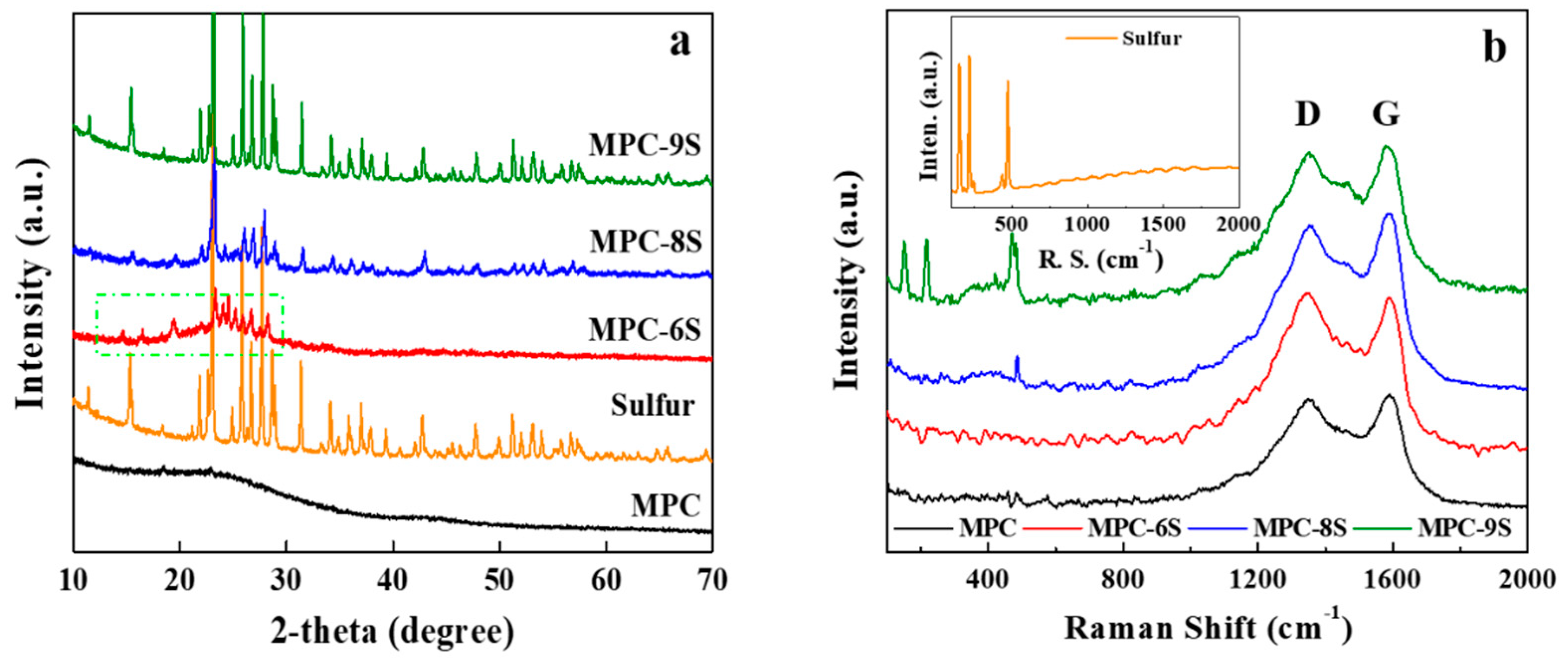
| Sulfur Content [wt%] | IG/ID | |
|---|---|---|
| MPC | - | 1.072 |
| MPC-6S | 54.47 | 1.036 |
| MPC-8S | 77.79 | 1.029 |
| MPC-9S | 91.33 | 0.971 |
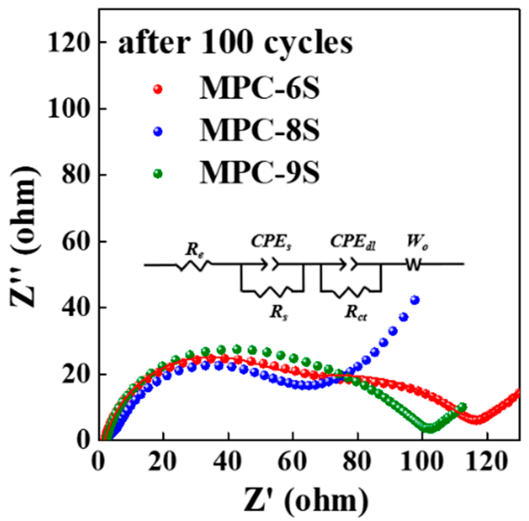
| Rs (Ω) | Rct (Ω) | |
|---|---|---|
| MPC-6S | 1.74 | 81.2 |
| MPC-8S | 1.37 | 60.1 |
| MPC-9S | 2.15 | 83.5 |
| Material for Carbonization | Activation Temperature (°C) | Surface Area (m2 g−1) | Pore Volume (cm3 g−1) | Capacity (mAh g−1) | Ref. |
|---|---|---|---|---|---|
| Banana peels | 900 | 194 | 2.40 | C dis = 832.4 mAh g−1 Cycle number = 200 Rate = 0.2 C | [24] |
| Bamboo leaves | 800 | 329 | 0.5 | C dis = 707 mAh g−1 Cycle number = 200 Rate = 1 C | [25] |
| Soybeans | 800 | 1500 | 0.7 | C dis = 460 mAh g−1 Cycle number = 800 Rate = 0.5 C | [26] |
| Corn cobs | 800 | 2724 | 1.46 | C dis = 720 mAh g−1 Cycle number = 150 Rate = 0.3 C | [27] |
| Pomelo peels | 600 | 1533 | 0.837 | C dis = 750 mAh g−1 Cycle number = 100 Rate = 0.2 C | [28] |
| Shaddock peels | 900 | 937.1 | 0.82 | C dis = 619.8 mAh g−1 Cycle number = 100 Rate = 0.5 C | [29] |
| Poplar catkins | 800 | 186 | 0.287 | C dis = 810 mAh g−1 Cycle number = 100 Rate = 0.1 C | [30] |
| Kapok fibers | 700 | 282.38 | 0.1574 | C dis = 524 mAh g−1 Cycle number = 90 Rate = 0.4 A g−1 | [31] |
| Milkweed pappuss | 800 | 1056 | 0.48 | C dis = 743 mAh g−1 Cycle number = 200 Rate = 0.5 C | This work |
Publisher’s Note: MDPI stays neutral with regard to jurisdictional claims in published maps and institutional affiliations. |
© 2022 by the authors. Licensee MDPI, Basel, Switzerland. This article is an open access article distributed under the terms and conditions of the Creative Commons Attribution (CC BY) license (https://creativecommons.org/licenses/by/4.0/).
Share and Cite
Kim, J.-K.; Choi, Y.; Jeong, E.D.; Lee, S.-J.; Kim, H.G.; Chung, J.M.; Kim, J.-S.; Lee, S.-Y.; Bae, J.-S. Synthesis and Electrochemical Performance of Microporous Hollow Carbon from Milkweed Pappus as Cathode Material of Lithium–Sulfur Batteries. Nanomaterials 2022, 12, 3605. https://doi.org/10.3390/nano12203605
Kim J-K, Choi Y, Jeong ED, Lee S-J, Kim HG, Chung JM, Kim J-S, Lee S-Y, Bae J-S. Synthesis and Electrochemical Performance of Microporous Hollow Carbon from Milkweed Pappus as Cathode Material of Lithium–Sulfur Batteries. Nanomaterials. 2022; 12(20):3605. https://doi.org/10.3390/nano12203605
Chicago/Turabian StyleKim, Jun-Ki, Yunju Choi, Euh Duck Jeong, Sei-Jin Lee, Hyun Gyu Kim, Jae Min Chung, Jeom-Soo Kim, Sun-Young Lee, and Jong-Seong Bae. 2022. "Synthesis and Electrochemical Performance of Microporous Hollow Carbon from Milkweed Pappus as Cathode Material of Lithium–Sulfur Batteries" Nanomaterials 12, no. 20: 3605. https://doi.org/10.3390/nano12203605