

Controlled Crystal Growth of All-Inorganic CsPbI2.2Br0.8 Thin Film via Additive Strategy for Air-Processed Efficient Outdoor/Indoor Perovskite Solar Cells
 and
and
Abstract
:
1. Introduction
2. Materials and Methods
2.1. Materials
2.2. Preparation of Precursor Solutions
2.3. Fabrication of Perovskite Solar Cells
2.4. Characterization Techniques
3. Results and Discussion
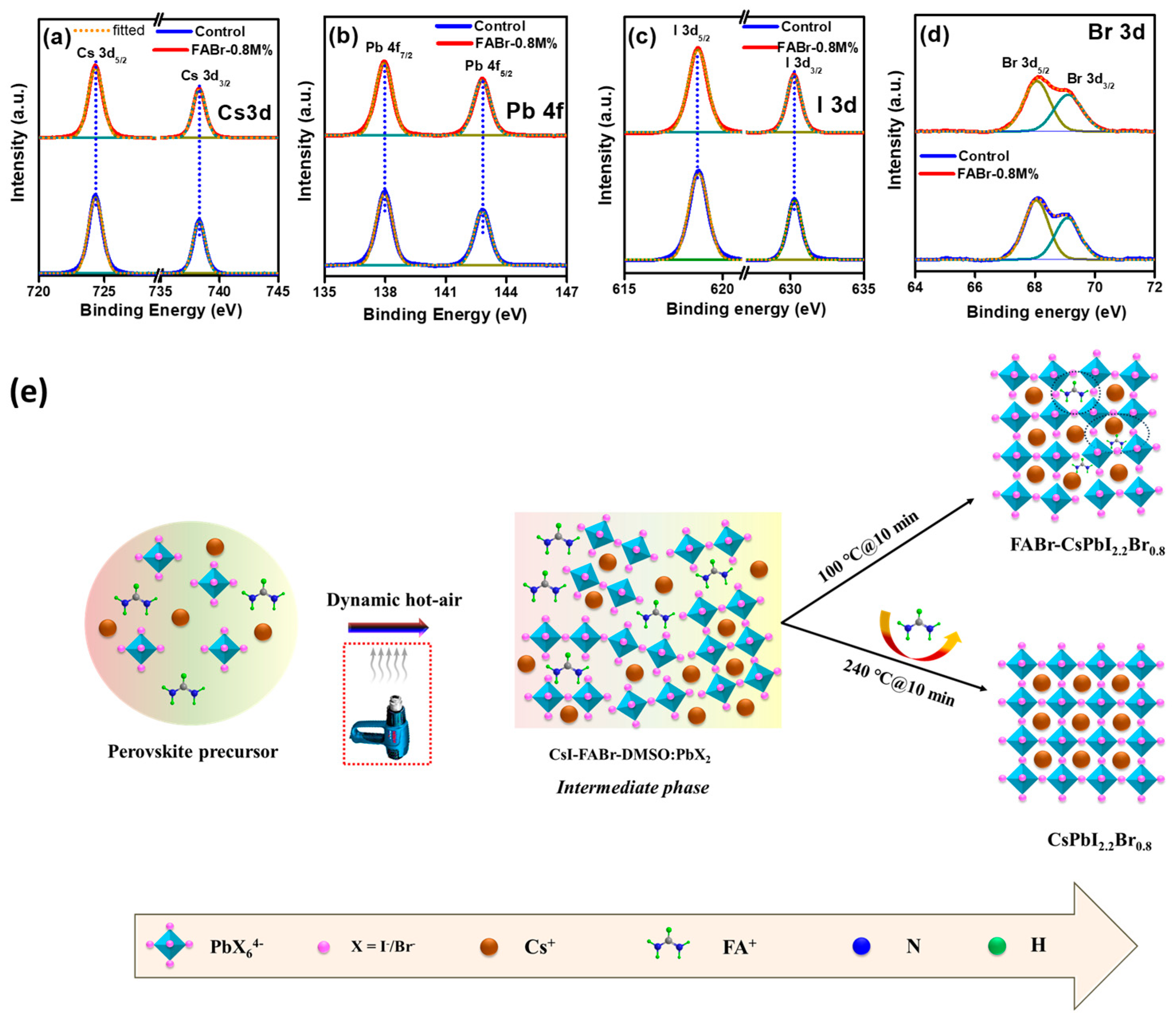
3.1. Proposed Mechanism, Morphological, Structural, and Optoelectronic Properties of Films
3.2. Investigation of PV Parameters, Defect States, and Charge Carrier Dynamics of PSCs
3.3. Investigation of Indoor PV Parameters and Long-Term Stability of PSCs
4. Conclusions
Supplementary Materials
Author Contributions
Funding
Data Availability Statement
Conflicts of Interest
References
- Lee, D.S.; Yun, J.S.; Kim, J.; Soufiani, A.M.; Chen, S.; Cho, Y.; Deng, X.; Seidel, J.; Lim, S.; Huang, S. Passivation of grain boundaries by phenethylammonium in formamidinium-methylammonium lead halide perovskite solar cells. ACS Energy Lett. 2018, 3, 647–654. [Google Scholar] [CrossRef]
- Thakur, U.K.; Kumar, P.; Gusarov, S.; Kobryn, A.E.; Riddell, S.; Goswami, A.; Alam, K.M.; Savela, S.; Kar, P.; Thundat, T. Consistently High V oc Values in pin Type Perovskite Solar Cells Using Ni3+-Doped NiO Nanomesh as the Hole Transporting Layer. ACS Appl. Mater. Interfaces 2020, 10, 11467–11478. [Google Scholar] [CrossRef]
- Jiang, J.; Li, R.; Liu, D.; Xie, H.; Zeng, Q.; Li, Y. Efficient and Stable CsPbI2Br Inorganic Perovskite Solar Cell Co-Modified with Ionic Liquids and Quantum Dots. ACS Appl. Energy Mater. 2023, 10, 5378–5387. [Google Scholar] [CrossRef]
- Wang, H.; Bian, H.; Jin, Z.; Zhang, H.; Liang, L.; Wen, J.; Wang, Q.; Ding, L.; Liu, S.F. Cesium lead mixed-halide perovskites for low-energy loss solar cells with efficiency beyond 17%. Chem. Mater. 2019, 16, 6231–6238. [Google Scholar] [CrossRef]
- Kojima, A.; Teshima, K.; Shirai, Y.; Miyasaka, T. Organometal halide perovskites as visible-light sensitizers for photovoltaic cells. J. Am. Chem. Soc. 2009, 17, 6050–6051. [Google Scholar] [CrossRef] [PubMed]
- Park, J.; Kim, J.; Yun, H.-S.; Paik, M.J.; Noh, E.; Mun, H.J.; Kim, M.G.; Shin, T.J.; Seok, S.I. Controlled growth of perovskite layers with volatile alkylammonium chlorides. Nature 2023, 7958, 724–730. [Google Scholar] [CrossRef]
- Arora, N.; Dar, M.I.; Hinderhofer, A.; Pellet, N.; Schreiber, F.; Zakeeruddin, S.M.; Grätzel, M. Perovskite solar cells with CuSCN hole extraction layers yield stabilized efficiencies greater than 20%. Science 2017, 6364, 768–771. [Google Scholar] [CrossRef] [PubMed]
- Zhao, X.; Liu, T.; Burlingame, Q.C.; Liu, T.; Holley, R., III; Cheng, G.; Yao, N.; Gao, F.; Loo, Y.-L. Accelerated aging of all-inorganic, interface-stabilized perovskite solar cells. Science 2022, 6603, 307–310. [Google Scholar] [CrossRef] [PubMed]
- Duan, C.; Wen, Q.; Fan, Y.; Li, J.; Liu, Z.; Yan, K. Improving the stability and scalability of all-inorganic inverted CsPbI2Br perovskite solar cell. J. Energy Chem. 2022, 68, 176–183. [Google Scholar] [CrossRef]
- Zheng, S.; Wang, H.; Wei, P.; Chen, H.; Xie, Y. Enhancing the performance and stability of carbon-based CsPbI2Br perovskite solar cells via tetrabutylammonium iodide surface passivation. Sol. Energy 2021, 230, 666–674. [Google Scholar] [CrossRef]
- Zheng, Y.; Yang, X.; Su, R.; Wu, P.; Gong, Q.; Zhu, R. High-performance CsPbIxBr3-x all-inorganic perovskite solar cells with efficiency over 18% via spontaneous interfacial manipulation. Adv. Funct. Mater. 2020, 46, 2000457. [Google Scholar] [CrossRef]
- Zeng, Q.; Zhang, X.; Liu, C.; Feng, T.; Chen, Z.; Zhang, W.; Zheng, W.; Zhang, H.; Yang, B. Inorganic CsPbI2Br perovskite solar cells: The progress and perspective. Sol. Rrl 2019, 1, 1800239. [Google Scholar] [CrossRef]
- Liu, X.; Jiang, J.; Wang, F.; Xiao, Y.; Sharp, I.D.; Li, Y. High photovoltage inverted planar heterojunction perovskite solar cells with all-inorganic selective contact layers. ACS Appl. Mater. Interfaces 2019, 50, 46894–46901. [Google Scholar] [CrossRef]
- Lau, C.F.J.; Wang, Z.; Sakai, N.; Zheng, J.; Liao, C.H.; Green, M.; Huang, S.; Snaith, H.J.; Ho-Baillie, A. Fabrication of efficient and stable CsPbI3 perovskite solar cells through cation exchange process. Adv. Energy Mater. 2019, 36, 1901685. [Google Scholar] [CrossRef]
- Liu, C.; Yang, Y.; Xia, X.; Ding, Y.; Arain, Z.; An, S.; Liu, X.; Cristina, R.C.; Dai, S.; Nazeeruddin, M.K. Soft template-controlled growth of high-quality CsPbI3 films for efficient and stable solar cells. Adv. Energy Mater. 2020, 9, 1903751. [Google Scholar] [CrossRef]
- Chen, W.; Zhang, J.; Xu, G.; Xue, R.; Li, Y.; Zhou, Y.; Hou, J.; Li, Y. A semitransparent inorganic perovskite film for overcoming ultraviolet light instability of organic solar cells and achieving 14.03% efficiency. Adv. Mater. 2018, 21, 1800855. [Google Scholar] [CrossRef]
- Han, Q.; Yang, S.; Wang, L.; Yu, F.; Zhang, C.; Wu, M.; Ma, T. The sulfur-rich small molecule boosts the efficiency of carbon-based CsPbI2Br perovskite solar cells to approaching 14%. Sol. Energy 2021, 216, 351–357. [Google Scholar] [CrossRef]
- Yu, L.; Guo, T.; Yuan, H.; Zhang, Z.; Deng, Z.; Zhao, R.; Zheng, M.; Zhang, J.; Xu, W.; Liu, X. Effective lewis base additive with S-donor for efficient and stable CsPbI2Br based perovskite solar cells. Chem. Eng. J. 2021, 420, 129931. [Google Scholar] [CrossRef]
- Fang, Z.; Liu, L.; Zhang, Z.; Yang, S.; Liu, F.; Liu, M.; Ding, L. CsPbI2.25Br0.75 solar cells with 15.9% efficiency. Sci. Bull. 2019, 8, 507–510. [Google Scholar] [CrossRef]
- Zhang, J.; Wang, Z.; Mishra, A.; Yu, M.; Shasti, M.; Tress, W.; Kubicki, D.J.; Avalos, C.E.; Lu, H.; Liu, Y. Intermediate phase enhances inorganic perovskite and metal oxide interface for efficient photovoltaics. Joule 2020, 1, 222–234. [Google Scholar] [CrossRef]
- Duan, L.; Wang, Z.; Li, Y.; Tan, L.; Zhang, Z.; Wang, H.; Yi, C.; Hagfeldt, A.; Luo, J. Hydrophobic organic ammonium halide modification toward highly efficient and stable CsPbI2.25Br0.75 solar cell. Sol. Rrl 2021, 7, 2100178. [Google Scholar] [CrossRef]
- Bahadur, J.; Ryu, J.; Pandey, P.; Cho, S.; Cho, J.S.; Kang, D.-W. In situ crystal reconstruction strategy-based highly efficient air-processed inorganic CsPbI2Br perovskite photovoltaics for indoor, outdoor, and switching applications. Nanoscale 2023, 8, 3850–3863. [Google Scholar] [CrossRef]
- Chen, S.-C.; Wang, D.; Zheng, Q. Surface Passivation of All-Inorganic CsPbI2Br with a Fluorinated Organic Ammonium Salt for Perovskite Solar Cells with Efficiencies over 16%. Sol. RRL 2020, 10, 2000321. [Google Scholar] [CrossRef]
- Mali, S.S.; Patil, J.V.; Shinde, P.S.; de Miguel, G.; Hong, C.K. Fully air-processed dynamic hot-air-assisted M: CsPbI2Br (M: Eu2+, In3+) for stable inorganic perovskite solar cells. Matter 2021, 2, 635–653. [Google Scholar] [CrossRef]
- Dong, C.; Han, X.; Zhao, Y.; Li, J.; Chang, L.; Zhao, W. A green anti-solvent process for high performance carbon-based CsPbI2Br all-inorganic perovskite solar cell. Solar RRL 2018, 9, 1800139. [Google Scholar] [CrossRef]
- Liu, C.; Li, W.; Li, H.; Wang, H.; Zhang, C.; Yang, Y.; Gao, X.; Xue, Q.; Yip, H.L.; Fan, J. Structurally reconstructed CsPbI2Br perovskite for highly stable and square-centimeter all-inorganic perovskite solar cells. Adv. Energy Mater. 2019, 7, 1803572. [Google Scholar] [CrossRef]
- Wang, K.; Zhou, J.; Li, X.; Ahmad, N.; Xia, H.; Wu, G.; Zhang, X.; Wang, B.; Zhang, D.; Zou, Y. A surface modifier enhances the performance of the all-inorganic CsPbI2Br perovskite solar cells with efficiencies approaching 15%. Phys. Chem. Chem. Phys. 2020, 32, 17847–17856. [Google Scholar] [CrossRef] [PubMed]
- Tian, J.; Zhang, K.; Xie, Z.; Peng, Z.; Zhang, J.; Osvet, A.; Lüer, L.; Kirchartz, T.; Rau, U.; Li, N. Quantifying the Energy Losses in CsPbI2Br Perovskite Solar Cells with an Open-Circuit Voltage of up to 1.45 V. ACS Energy Lett. 2022, 11, 4071–4080. [Google Scholar] [CrossRef]
- Zhou, Q.; Cai, C.; Xiong, Q.; Zhang, Z.; Xu, J.; Liang, L.; Wang, S.; Sun, W.; Yuan, Z.; Gao, P. Surface Polarity Regulation by Relieving Fermi-Level Pinning with Naphthalocyanine Tetraimides toward Efficient Perovskite Solar Cells with Improved Photostability. Adv. Energy Mater. 2022, 27, 2201243. [Google Scholar] [CrossRef]
- Li, D.; Huang, Y.; Ma, R.; Liu, H.; Liang, Q.; Han, Y.; Ren, Z.; Liu, K.; Fong, P.W.K.; Zhang, Z. Surface Regulation with Polymerized Small Molecular Acceptor towards Efficient Inverted Perovskite Solar Cells. Adv. Energy Mater. 2023, 18, 2204247. [Google Scholar] [CrossRef]
- Yue, X.; Yang, Y.; Zhao, X.; Fan, B.; Yan, H.; Qu, S.; Zhang, Q.; Lan, Z.; Du, S.; Huang, H. In situ surface regulation of 3D perovskite using diethylammonium iodide for highly efficient perovskite solar cells. Phys. Chem. Chem. Phys. 2023, 13, 9349–9356. [Google Scholar] [CrossRef] [PubMed]
- Li, X.; Ying, Z.; Zheng, J.; Wang, X.; Chen, Y.; Wu, M.; Xiao, C.; Sun, J.; Shou, C.; Yang, Z. Surface Reconstruction for Efficient and Stable Monolithic Perovskite/Silicon Tandem Solar Cells with Greatly Suppressed Residual Strain. Adv. Mater. 2023, 35, 2211962. [Google Scholar] [CrossRef] [PubMed]
- Xu, Y.; Ren, Y.; Cheng, S.; Zhang, L.; Niu, P.; Lyu, M.; Lu, H.; Wang, M.; Zhu, J. A residual strain regulation strategy based on quantum dots for efficient perovskite solar cells. J. Mater. Chem. A 2023, 2, 868–877. [Google Scholar] [CrossRef]
- Mohanta, M.K.; Is, F.; Kishore, A.; De Sarkar, A. Spin-current modulation in hexagonal buckled ZnTe and CdTe monolayers for self-powered flexible-piezo-spintronic devices. ACS Appl. Mater. Interfaces 2021, 34, 40872–40879. [Google Scholar] [CrossRef]
- Patil, J.V.; Mali, S.S.; Hong, C.K. Reducing defects of all-inorganic γ-CsPbI2Br thin films by ethylammonium bromide additives for efficient perovskite solar cells. ACS Appl. Mater. Interfaces 2022, 22, 25576–25583. [Google Scholar] [CrossRef]
- Bahadur, J.; Ryu, J.; Lee, D.-G.; Hong, J.; Hayase, S.; Cho, J.S.; Jeong, S.M.; Kang, D.-W. In-situ surface defects passivation with small carbon chain molecules for highly efficient, air-processed inorganic CsPbI2Br perovskite photovoltaics. Appl. Surf. Sci. 2023, 614, 156229. [Google Scholar] [CrossRef]
- Zhang, C.; Wan, X.; Zang, J.; Liu, Q.; Fei, Y.; Yu, Z. Polymer-modified CsPbI2Br films for all-inorganic planar perovskite solar cells with improved performance. Surf. Interfaces 2021, 22, 100809. [Google Scholar] [CrossRef]
- Jin, I.S.; Parida, B.; Jung, J.W. Simultaneously enhanced efficiency and ambient stability of inorganic perovskite solar cells by employing tetramethylammonium chloride additive in CsPbI2Br. J. Mater. Sci. Technol. 2022, 102, 224–231. [Google Scholar] [CrossRef]
- Li, H.; Hao, X.; Chang, B.; Li, Z.; Wang, L.; Pan, L.; Chen, X.; Yin, L. Stiffening the Pb-X framework through a π-conjugated small-molecule cross-linker for high-performance inorganic CsPbI2Br perovskite solar cells. ACS Appl. Mater. Interfaces 2021, 34, 40489–40501. [Google Scholar] [CrossRef]
- Fu, S.; Wang, J.; Liu, X.; Yuan, H.; Xu, Z.; Long, Y.; Zhang, J.; Huang, L.; Hu, Z.; Zhu, Y. Multifunctional liquid additive strategy for highly efficient and stable CsPbI2Br all-inorganic perovskite solar cells. Chem. Eng. J. 2021, 422, 130572. [Google Scholar] [CrossRef]
- Bahadur, J.; Cho, S.; Pandey, P.; Ryu, J.; Yoon, S.; Lee, D.-G.; Song, J.T.; Cho, J.S.; Kang, D.-W. Surface defect passivation of All-Inorganic CsPbI2Br perovskites via fluorinated ionic liquid for efficient Outdoor/Indoor photovoltaics processed in ambient air. Appl. Surf. Sci. 2023, 637, 157901. [Google Scholar] [CrossRef]
- Mali, S.S.; Patil, J.V.; Hong, C.K. Hot-air-assisted fully air-processed barium incorporated CsPbI2Br perovskite thin films for highly efficient and stable all-inorganic perovskite solar cells. Nano Lett. 2019, 9, 6213–6220. [Google Scholar] [CrossRef] [PubMed]
- Wu, N.; Yang, T.; Wang, Z.; Wu, Y.; Wang, Y.; Ma, C.; Li, H.; Du, Y.; Zhao, D.; Wang, S. Stabilizing precursor solution and controlling crystallization kinetics simultaneously for high-performance perovskite solar cells. Adv. Mater. 2023, 2304809. [Google Scholar] [CrossRef] [PubMed]
- Ma, R.; Li, H.; Peña, T.A.D.; Xie, X.; Fong, P.W.K.; Wei, Q.; Yan, C.; Wu, J.; Cheng, P.; Li, M. Tunable Donor Aggregation Dominance in Ternary Matrix of All-polymer Blends with Improved Efficiency and Stability. Adv. Mater. 2023, 2304632. [Google Scholar] [CrossRef] [PubMed]
- Lee, J.W.; Lim, C.; Lee, S.W.; Jeon, Y.; Lee, S.; Kim, T.S.; Lee, J.Y.; Kim, B.J. Intrinsically Stretchable and Non-Halogenated Solvent Processed Polymer Solar Cells Enabled by Hydrophilic Spacer-Incorporated Polymers. Adv. Energy Mater. 2022, 46, 2202224. [Google Scholar] [CrossRef]
- Li, Y.; Duan, J.; Yuan, H.; Zhao, Y.; He, B.; Tang, Q. Lattice modulation of alkali metal cations doped Cs1−xRxPbBr3 halides for inorganic perovskite solar cells. Sol. RRL 2018, 10, 1800164. [Google Scholar] [CrossRef]
- Zhang, W.; Xiong, J.; Li, J.; Daoud, W.A. Guanidinium Passivation for Air-Stable Rubidium-Incorporated Cs(1−x)RbxPbI2Br Inorganic Perovskite Solar Cells. Solar RRL 2020, 6, 2000112. [Google Scholar] [CrossRef]
- Patil, J.V.; Mali, S.S.; Hong, C.K. Grain size enlargement and controlled crystal growth by formamidinium chloride additive-added γ-CsPbI2Br thin films for stable inorganic perovskite solar cells. Mater. Today Chem. 2022, 26, 101118. [Google Scholar] [CrossRef]
- Khalid, S.; Malik, M.A.; Lewis, D.J.; Kevin, P.; Ahmed, E.; Khan, Y.; O’Brien, P. Transition metal doped pyrite (FeS2) thin films: Structural properties and evaluation of optical band gap energies. J. Mater. Chem. C 2015, 46, 12068–12076. [Google Scholar] [CrossRef]
- Mote, V.; Purushotham, Y.; Dole, B. Williamson-Hall analysis in estimation of lattice strain in nanometer-sized ZnO particles. J. Theor. Appl. Phys. 2012, 6, 6. [Google Scholar] [CrossRef]
- Fu, S.; Zhang, W.; Li, X.; Wan, L.; Wu, Y.; Chen, L.; Liu, X.; Fang, J. Dual-protection strategy for high-efficiency and stable CsPbI2Br inorganic perovskite solar cells. ACS Energy Lett. 2020, 2, 676–684. [Google Scholar] [CrossRef]
- Li, H.; Yin, L. Efficient Bidentate Molecules Passivation Strategy for High-Performance and Stable Inorganic CsPbI2Br Perovskite Solar Cells. Sol. RRL 2020, 10, 2000268. [Google Scholar] [CrossRef]
- Grischek, M.; Caprioglio, P.; Zhang, J.; Pena-Camargo, F.; Sveinbjörnsson, K.; Zu, F.; Menzel, D.; Warby, J.H.; Li, J.; Koch, N. Efficiency Potential and Voltage Loss of Inorganic CsPbI2Br Perovskite Solar Cells. Sol. RRL 2022, 11, 2200690. [Google Scholar] [CrossRef]
- Jin, Z.; Yuan, M.; Li, H.; Yang, H.; Zhou, Q.; Liu, H.; Lan, X.; Liu, M.; Wang, J.; Sargent, E.H. Graphdiyne: An efficient hole transporter for stable high-performance colloidal quantum dot solar cells. Adv. Funct. Mater. 2016, 29, 5284–5289. [Google Scholar] [CrossRef]
- Niu, G.; Li, W.; Meng, F.; Wang, L.; Dong, H.; Qiu, Y. Study on the stability of CH3NH3PbI3 films and the effect of post-modification by aluminum oxide in all-solid-state hybrid solar cells. J. Mater. Chem. A 2014, 3, 705–710. [Google Scholar] [CrossRef]
- Guerrero, A.; Bisquert, J.; Garcia-Belmonte, G. Impedance spectroscopy of metal halide perovskite solar cells from the perspective of equivalent circuits. Chem. Rev. 2021, 23, 14430–14484. [Google Scholar] [CrossRef]
- Yang, Y.; Song, J.; Zhao, Y.; Zhu, L.; Gu, X.; Gu, Y.; Che, M.; Qiang, Y. Ammonium-iodide-salt additives induced photovoltaic performance enhancement in one-step solution process for perovskite solar cells. J. Alloys Compd. 2016, 684, 84–90. [Google Scholar] [CrossRef]
- Song, J.; Li, S.; Zhao, Y.; Yuan, J.; Zhu, Y.; Fang, Y.; Zhu, L.; Gu, X.; Qiang, Y. Performance enhancement of perovskite solar cells by doping TiO2 blocking layer with group VB elements. J. Alloys Compd. 2017, 694, 1232–1238. [Google Scholar] [CrossRef]
- Bi, Z.; Xu, X.; Chen, X.; Zhu, Y.; Liu, C.; Yu, H.; Zheng, Y.; Troshin, P.A.; Guerrero, A.; Xu, G. High-performance large-area blade-coated perovskite solar cells with low ohmic loss for low lighting indoor applications. Chem. Eng. J. 2022, 446, 137164. [Google Scholar] [CrossRef]
- Sha, W.E.; Zhang, H.; Wang, Z.S.; Zhu, H.L.; Ren, X.; Lin, F.; Jen, A.K.Y.; Choy, W.C. Quantifying efficiency loss of perovskite solar cells by a modified detailed balance model. Adv. Energy Mater. 2018, 8, 1701586. [Google Scholar] [CrossRef]
- Chen, F.C. Emerging organic and organic/inorganic hybrid photovoltaic devices for specialty applications: Low-level-lighting energy conversion and biomedical treatment. Adv. Opt. Mater. 2019, 1, 1800662. [Google Scholar] [CrossRef]
- Virtuani, A.; Lotter, E.; Powalla, M. Performance of Cu (In, Ga) Se2 solar cells under low irradiance. Thin Solid Film. 2003, 431, 443–447. [Google Scholar] [CrossRef]
- Vincent, P.; Shin, S.-C.; Goo, J.S.; You, Y.-J.; Cho, B.; Lee, S.; Lee, D.-W.; Kwon, S.R.; Chung, K.-B.; Lee, J.-J. Indoor-type photovoltaics with organic solar cells through optimal design. Dye. Pigment. 2018, 159, 306–313. [Google Scholar] [CrossRef]
- Lee, J.W.; Park, N.G. Chemical approaches for stabilizing perovskite solar cells. Adv. Energy Mater. 2020, 1, 1903249. [Google Scholar] [CrossRef]
- Habisreutinger, S.N.; Noel, N.K.; Snaith, H.J. Hysteresis index: A figure without merit for quantifying hysteresis in perovskite solar cells. ACS Energy Lett. 2018, 10, 2472–2476. [Google Scholar] [CrossRef]
- Fang, Z.; Meng, X.; Zuo, C.; Li, D.; Xiao, Z.; Yi, C.; Wang, M.; Jin, Z.; Yang, S.; Ding, L. Interface engineering gifts CsPbI2. 25Br0. 75 solar cells high performance. Sci. Bull. 2019, 23, 1743–1746. [Google Scholar] [CrossRef]
- Xiao, H.; Zuo, C.; Zhang, L.; Zhang, W.; Hao, F.; Yi, C.; Liu, F.; Jin, H.; Ding, L. Efficient inorganic perovskite solar cells made by drop-coating in ambient air. Nano Energy 2023, 108061. [Google Scholar] [CrossRef]


| Devices | JSC (mA/cm2) | VOC (mV) | FF (%) | PCE (%) | |
|---|---|---|---|---|---|
| Control | Champion | 16.10 | 1230 | 80.51 | 15.94 |
| Average | 15.81 ± 0.29 | 1212 ± 18 | 79.50 ±1.01 | 15.23 ± 0.81 | |
| FABr-0.4M% | Champion | 16.42 | 1265 | 82.44 | 17.12 |
| Average | 16.21 ± 0.23 | 1250 ± 15 | 81.70 ± 0.74 | 16.55 ± 0.57 | |
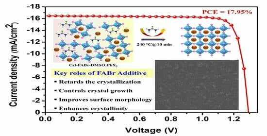
| FABr-0.8M% | Champion | 16.46 | 1293 | 84.36 | 17.95 |
| Average | 16.31 ± 0.15 | 1283 ± 10 | 83.80 ± 0.56 | 17.54 ± 0.42 | |
| FABr-1.2M% | Champion | 16.33 | 1224 | 81.22 | 16.23 |
| Average | 16.08 ± 0.25 | 1205 ± 19 | 80.37 ± 0.85 | 15.57 ± 0.66 |
| Devices | JSC (μA/cm2) | VOC (mV) | FF (%) | Pindoor (μW/cm2) | PCE (%) |
|---|---|---|---|---|---|
| Control | 169 | 980 | 53.12 | 88 | 23.15 |
| FABr-0.8M% | 201 | 1031 | 57.27 | 118.7 | 31.22 |
Disclaimer/Publisher’s Note: The statements, opinions and data contained in all publications are solely those of the individual author(s) and contributor(s) and not of MDPI and/or the editor(s). MDPI and/or the editor(s) disclaim responsibility for any injury to people or property resulting from any ideas, methods, instructions or products referred to in the content. |
© 2023 by the authors. Licensee MDPI, Basel, Switzerland. This article is an open access article distributed under the terms and conditions of the Creative Commons Attribution (CC BY) license (https://creativecommons.org/licenses/by/4.0/).
Share and Cite
Bahadur, J.; Ryu, J.; Cho, S.; Yoon, S.; Lee, D.-G.; Kang, D.-W.; Pandey, P. Controlled Crystal Growth of All-Inorganic CsPbI2.2Br0.8 Thin Film via Additive Strategy for Air-Processed Efficient Outdoor/Indoor Perovskite Solar Cells. Nanomaterials 2023, 13, 2716. https://doi.org/10.3390/nano13192716
Bahadur J, Ryu J, Cho S, Yoon S, Lee D-G, Kang D-W, Pandey P. Controlled Crystal Growth of All-Inorganic CsPbI2.2Br0.8 Thin Film via Additive Strategy for Air-Processed Efficient Outdoor/Indoor Perovskite Solar Cells. Nanomaterials. 2023; 13(19):2716. https://doi.org/10.3390/nano13192716
Chicago/Turabian StyleBahadur, Jitendra, Jun Ryu, SungWon Cho, Saemon Yoon, Dong-Gun Lee, Dong-Won Kang, and Padmini Pandey. 2023. "Controlled Crystal Growth of All-Inorganic CsPbI2.2Br0.8 Thin Film via Additive Strategy for Air-Processed Efficient Outdoor/Indoor Perovskite Solar Cells" Nanomaterials 13, no. 19: 2716. https://doi.org/10.3390/nano13192716