.jpg)
Application Research of Ultrasonic-Guided Wave Technology in Pipeline Corrosion Defect Detection: A Review

1
State Grid Wuxi Power Supply Company, Wuxi 214000, China
2
College of Materials Science and Engineering, Hohai University, Nanjing 211100, China
*
Author to whom correspondence should be addressed.
Coatings 2024, 14(3), 358; https://doi.org/10.3390/coatings14030358
Submission received: 16 January 2024
/
Revised: 23 February 2024
/
Accepted: 28 February 2024
/
Published: 18 March 2024
(This article belongs to the Special Issue Advances in the Preparation and Characterization Techniques for Developing Coating Materials and Applications)
Abstract
:This paper presents research on the application of ultrasonic-guided wave technology in corrosion defect identification, expounds the relevant ultrasonic-guided wave theories and the principle of ultrasonic-guided wave non-destructive testing of pipelines, and discusses the Lamb wave and shear horizontal wave mode selection that is commonly used in ultrasonic-guided wave corrosion detection. Furthermore, research progress in the field of ultrasonic-guided wave non-destructive testing (NDT) technology, i.e., regarding transducers, structural health monitoring, convolutional neural networks, machine learning, and other fields, is reviewed. Finally, the future prospects of ultrasonic-guided wave NDT technology are discussed.
1. Introduction
As vital components of industrial transportation, pipeline structures find extensive applications in fields such as petroleum, chemical engineering, aerospace, nuclear power, and more. During their service life, pipelines are susceptible to corrosion and degradation due to environmental and other factors. Detecting corrosion and pitting defects is crucial, as these can occur at various locations within pipelines and vessels, constituting a significant portion of maintenance expenditures. These issues can lead to pipeline cracking, leakage, reduced operational lifespan, and, in severe cases, catastrophic accidents resulting in significant economic losses [1,2,3,4,5,6,7]. Therefore, it is crucial to detect corrosion and pitting defects for the safety of the pipeline industry. It is necessary to conduct regular pipeline inspections and to provide maintenance and repair of pipeline structures, ensure the safe operation and use of pipelines, maximize the lifespan of pipelines, and pursue the most significant economic and social benefits [8,9].
Non-destructive testing (NDT) technology is a method used to detect various defects in components without causing damage to the inspected object or affecting the performance of the testing components. It provides information on the size, location, quantity, and severity of defects, allowing for the assessment of the component’s condition. NDT technology has widespread applications across multiple fields and is crucial in product quality inspections and equipment examinations. It makes it possible to identify the initial damage stage in structures, prevent structural failure, and reduce economic losses; it therefore serves as a valuable defect assessment method. Among the advantages of NDT are its remote controllability, ease of operation, and low operating costs [10,11,12,13,14].
In infrastructure maintenance, NDT for pipelines has become an essential practice. Standard techniques for pipeline defect identification include ultrasonic testing (UT), eddy current testing (ECT), radiographic testing (RT), penetrant testing (PT), and magnetic particle testing (MT) [15]. UT may be applied to various materials, including metals, non-metals, and composite materials. It offers advantages such as a broad inspection range, significant detection depth, precise defect localization, high sensitivity, low cost, lack of pollution, and ease of on-site use. However, UT is a point-by-point inspection method, resulting in relatively slow inspection speeds.
Eddy current testing is widely used in various industrial fields. The procedure makes it possible to perform rapid and automated inspections. However, this technique can only be employed for surface defect detection in electrically conductive materials. For seamless steel pipes such as those commonly used in pipelines, eddy current testing is too fast; as such, more precision is needed for individual pipe inspections. Magnetic particle testing is known for its high sensitivity and ability to visually display defects’ location and shape. However, this approach can only be used to detect surface defects in ferromagnetic materials. Radiographic testing may be applied to various materials, providing intuitive inspection results. However, it can be detrimental to the health of inspectors due to radiation exposure and is associated with high inspection costs and low efficiency. Traditional inspection methods involve point-by-point examinations in pressure pipelines, steam pipelines, gas pipelines, and similar structures, requiring significant work and demonstrating low efficiency. Metal defect features, such as general corrosion, result in an attenuation in the energy of a propagating wave due to the rough corroded surface, reducing the detection range. In contrast, defect sizes can reduce the detectable range for identification [15,16,17].
Ultrasonic-guided waves propagate along the walls of pipes over long distances, and their acoustic field covers the entire wall thickness of a pipe or plate. They possess high energy levels and experience minimal self-attenuation over extended distances. With strong penetrating capabilities, these waves can detect defects on the external surface and within the internal structure of components. This capability significantly enhances inspection efficiency and reduces the workload. As the theory of ultrasonic-guided waves has been more deeply researched, the application areas of ultrasonic-guided wave testing technology have gradually expanded, primarily in non-destructive testing and structural health monitoring.
Ultrasonic-guided wave technology is applied to the non-destructive testing of materials such as pipelines, steel rails, high-voltage transmission lines, plates, composite materials, and more. It is also used for damage detection and assessments of various structural components in engineering structures, including honeycomb structures, aircraft fuselage structures or components, and infrastructure [18,19,20,21,22,23,24,25,26,27]. For pipeline inspection, the utilization of the multimodal and dispersive characteristics of a guided wave is essential. Considering factors such as component properties, dispersion curves, and attenuation, it is crucial to excite the appropriate guided wave modes to detect various types and levels of defects. In the case of plate materials, ultrasonic-guided wave testing has proven to be an effective means of inspecting critical components in metal plates. This involves selecting suitable excitation methods to stimulate single-mode-guided waves. Analyzing the signals from the defect location provides information about the position, size, and shape of the defect [28].
Given the significance of pipeline corrosion detection and the diversity of research that has been carried out on ultrasonic-guided waves, there is currently only a limited number of comprehensive reviews of research on pipeline corrosion detection based on guided waves. Recognizing the necessity of such a review, this article provides a comprehensive overview of the research applications of ultrasonic-guided waves in detecting corrosion defects in pipelines. It primarily elucidates the relevant theories of pipeline ultrasonic-guided waves and discusses the modal selection of commonly used Lamb waves and shear horizontal waves in ultrasonic-guided wave corrosion detection. Additionally, the article explores the research progress in ultrasonic-guided wave non-destructive testing technology for structural health monitoring and the combination of ultrasonic-guided waves with fiber optic acoustics. The second section introduces the basic theory and technical characteristics of ultrasonic-guided wave detection, while the third section delves into the in-depth research on pipeline ultrasonic-guided wave detection technology, its development, and related transducer studies. The fourth section focuses on the application of ultrasonic-guided wave detection technology in structural health monitoring.
2. Ultrasonic-Guided Wave Fundamentals
2.1. Concept of Ultrasonic-Guided Waves
Ultrasonic-guided waves pertain to either supersonic or subsonic mechanical or elastic waves that propagate within a medium parallel to its boundary surfaces, exemplified by pipes and plates. The propagation state of UGW is influenced by the geometric shape of the waveguide. UGW comprises mechanical vibrations generated beneath the excitation source and subsequently propagated through the waveguide [27,28]. At the interfaces of elastic media, UGW can induce reflection, refraction, and waveform transformation. During propagation, UGW carries distinctive information about both the excitation source and the material. This unique characteristic, in conjunction with alterations in sound wave intensity, establishes physical properties such as the size and location of internal defects within the component [28].
Ultrasonic-guided waves emerge in elastic media when a particle is subjected to force, inducing neighboring particles to experience a distinct force and oscillate around their equilibrium positions. This sequential propagation results in the formation of mechanical waves. As ultrasonic waves traverse a medium of a particular size, they traverse discontinuous cross-sections, leading to multiple reflections, refraction, mode conversion, and interference. This culminates in the creation of plate-like ultrasonic-guided waves, commonly referred to as Lamb waves [29,30,31,32]. Classical surface wave propagation encompasses surface waves, Lamb waves, and Stonely waves. Strictly speaking, Lamb waves propagate in uniformly isotropic plates devoid of traction forces. Nevertheless, this term has been broadened to encompass diverse structures, including plates, multilayer boards, rods, pipes, and beyond, where Lamb wave-type propagation takes place. In Lamb waves, the components of the wave vector can be parallel or perpendicular to the vertical plane of particle vibration, in contrast to horizontal shear waves. As Lamb waves travel along a structure, particle motion takes place solely in the horizontal plane, perpendicular to the wave vector [32,33,34].
2.2. Group Velocity and Phase Velocity of Guided Waves
In guided wave theory, the fundamental concepts of group velocity () and phase velocity () play a crucial role. Owing to the dispersion characteristics, guided waves manifest multiple frequencies as they propagate. Group velocity denotes the speed at which an entire pulse wave propagates and encompasses a family of waves with comparable frequencies. This is the speed at which the energy of the waveform travels. In the realm of guided waves, it elucidates the movement of a guided wave pulse through the medium. Conversely, phase velocity pertains to the speed at which a fixed phase point on a guided wave travels in the direction of propagation. In simple terms, it signifies the speed at which a point on the wave with a constant phase moves through the medium. However, in the majority of cases, especially when dealing with guided waves in waveguides, the term “propagation velocity” typically pertains to the group velocity, providing an overall description of how guided waves traverse the medium [28,35]. The formulas for calculating group and phase velocities are typically employed based on known frequencies.
2.3. The Excitation and Attenuation of Guided Waves
The guided wave testing of pipelines offers broad coverage for long-distance pipelines, but its detectable range is constrained by various attenuation factors, encompassing energy dispersion and absorption [16]. In elastic materials, wavefront dispersion is a prevalent phenomenon. In contrast, viscoelastic materials not only demonstrate wavefront dispersion but also manifest energy absorption phenomena [36].
The attenuation of guided waves denotes the phenomenon where the energy of the waves progressively diminishes as they propagate through a medium with an increasing propagation distance. The principal factors contributing to the attenuation of guided waves include diffusive attenuation, scattering attenuation, and absorption attenuation. Diffusive attenuation arises as guided waves propagate over distances, leading to the continuous expansion of non-planar wavefronts, resulting in a reduction of acoustic energy per unit area as the distance increases. Scattering attenuation: Scattering attenuation stems from non-uniformities in the material, resulting in variations in the acoustic impedance of the medium. This induces the scattering of guided waves, generating thermal energy as the waves persist in their propagation. Absorption attenuation: Absorption attenuation takes place as guided waves propagate through a medium due to the viscous properties of the material, leading to internal friction between particles and the conversion of some acoustic energy into thermal energy [37]. When performing guided wave testing of pipeline structures, scattering and diffusive attenuation are typically the more significant factors to consider.
2.4. Dispersion and Multimodal Characteristics of Guided Waves
Leveraging plate and shell theory, Gazis investigated the propagation of guided waves in infinite hollow cylindrical structures. He acquired comprehensive analytical solutions for both axisymmetric- and non-axisymmetric-guided wave modes within an infinite hollow cylindrical structure. He deduced frequency equations for diverse guided wave modes in hollow cylindrical structures, illustrated dispersion curves depicting the propagation of guided waves in hollow pipes, and ascertained cutoff frequencies for distinct modes. His contributions have laid a theoretical groundwork for subsequent studies on guided waves in pipelines [38,39]. Wave dispersion pertains to the alteration of group velocity and phase velocity with frequency during the propagation of guided waves. Dispersion arises from both geometric and physical factors. When ultrasonic waves propagate in waveguides like plates and pipes, the velocity of the waves varies with frequency owing to the geometric dimensions of the material structure, resulting in geometric dispersion.
Conversely, physical dispersion arises from the alterations in the physical properties of the waveguide material itself. When guided waves traverse a pipeline, the group velocity and phase velocity fluctuate with the product of frequency and thickness (frequency-thickness product). The structural dimensions and frequency predominantly influence the propagation of guided waves within the pipeline. Owing to the impact of dispersion characteristics, guided waves with distinct frequencies exhibit varying propagation speeds. Consequently, guided wave echoes with identical characteristics reach the transducer at different times. As a result, the echo waveform progressively broadens in the time domain as the propagation distance increases, giving rise to spatial energy dispersion. Subsequently, this influences signal sensitivity and the signal-to-noise ratio, affecting the inspection outcomes. Owing to the curvature of pipes and dispersion characteristics, wave propagation in such structures becomes intricate and encompasses an infinite array of possible wave modes.
Meitzler categorized modal-guided waves in hollow cylindrical pipes into three classes: longitudinal modes L (n, m), torsional modes T (n, m), and flexural modes F (n, m). Here, m symbolizes the azimuthal harmonic number, and n signifies the order of the guided wave mode. When n = 0 denotes an axisymmetric mode, n > 0 indicates a non-axisymmetric mode [40]. The multimodal nature of guided waves implies that various modes of guided waves propagate concurrently at the same frequency. In pipes, for instance, within the longitudinal modal-guided waves, the vibration displacement predominantly occurs in the axial and radial directions. Conversely, the torsional modal-guided waves mainly entail circumferential motion. The flexural modal-guided waves display concurrent axial, circumferential, and radial displacement and are deemed non-axisymmetric modes. Rose developed a methodology for solving dispersion curves of hollow cylindrical-guided waves, considering the geometry and material properties of pipes. This method illustrates the correlation between the nature of these wave modes and their frequencies. Figure 1 presents an example of a dispersion curve for a 3-inch Schedule 40 steel pipe [29,41].
Dispersion and multimodality stand out as pivotal traits in the propagation of guided waves within pipelines. Frequency-domain dispersion results in spectrum broadening as frequency components, initially with the same phase shift when passing through the waveguide, causing diminished frequency resolution [42]. In testing scenarios, the multimodal characteristic of guided waves can result in mode interference, diminishing signal sensitivity and the signal-to-noise ratio, adversely affecting accurate detection. Nevertheless, if the multimodal characteristics are efficiently harnessed, they can augment the detection process. Different modes display diverse sensitivity to various defect types. Utilizing multimodal characteristics enables the collection of more detection information, thereby enhancing the accuracy of the detection results. In engineering applications such as pipeline inspection, waveguides can accommodate multiple guided wave modes, each possessing distinct energy and excitability characteristics. Hence, relying on the multimodal and dispersion characteristics of ultrasonic-guided waves, it is crucial to select suitable guided wave modes and frequencies based on specific inspection requirements and dispersion properties to attain more sensitive and accurate detection results. In practical inspections, factors like instrument constraints and coupling conditions can impact precise mode control. Therefore, in most cases, it is recommended to choose excitation frequencies with fewer modes on the dispersion curve to minimize the occurrence of multimodal effects and mitigate the impact of dispersion on the inspection process.
The utilization of ultrasonic-guided wave technology in pipeline inspection stems from the exploration of both axisymmetric- and non-axisymmetric-guided wave modes [43]. Ultrasonic-guided waves showcase multimodal characteristics, requiring deliberations on mode selection in guided wave inspections. Both axisymmetric and non-axisymmetric mode-guided waves find application in long-distance pipeline inspections. The most extensively investigated and commercially established applications of ultrasonic-guided wave detection technology encompass the axisymmetric longitudinal mode L (0, 2) and torsional mode T (0, 1) guided waves. Nevertheless, employing multimodal excitations amplifies the complexity and challenges in analyzing reflected signals [44,45,46].
In practical applications, the axisymmetric longitudinal mode L (0, 2) is widely adopted due to its ease of excitation and absence of dispersion within a specific frequency range, among other favorable characteristics. When the L (0, 2) mode is introduced into a pipeline, it often simultaneously excites the low-order longitudinal mode L (0, 1) guided wave, which is commonly used in pipeline inspections [29,47]. The predominant motion direction of guided wave pipeline particles in the L (0, 2) mode is axial displacement. In this mode, both group velocity and phase velocity show limited changes with frequency across a broad frequency range, yielding a stable and readily identifiable waveform. Furthermore, the L (0, 2) mode undergoes comparatively low energy attenuation during propagation within the pipeline, rendering it suitable for long-distance transmission. Moreover, the L (0, 2) mode is the fastest propagating mode and demonstrates equal sensitivity to internal and external surface defects, as well as defects along the thickness direction [39,48,49,50]. While the L (0, 1) mode frequently coexists with the L (0, 2) mode, its slower group velocity can be eliminated in the time domain or suppressed by incorporating a ring into the transducer or adjusting the length of the transducer unit.
Researchers have comprehensively examined and applied the torsional mode T (0, 1) as well. Based on dispersion curves, it is observable that T (0, 1) exhibits non-dispersive advantages across the complete frequency spectrum. If the excitation signal frequency stays below the cutoff frequency of other torsional modes, such as T (0, 2), they do not become excited [30,51,52,53,54]. In the T (0, 1) mode, the primary motion direction of pipeline particles is circumferential displacement. T (0, 1) guided waves display non-dispersive characteristics throughout all frequency ranges. Additionally, longitudinal waves are prone to circumferential defects in pipelines, whereas torsional waves exhibit greater sensitivity to axial defects [19,48,53]. T (0, 1) is more sensitive to pipeline axial cracks than L (0, 2). In addition to axisymmetric modes, in some cases, non-axisymmetric modes are also employed for damage detection in pipelines after appropriate mode tuning. These non-axisymmetric modes are sensitive to different types of defects, and therefore, the choice of excitation method and frequency should be tailored to the type of defect. Longitudinal guided waves, characterized by fast propagation speed and long detection distances, offer advantages in the inspection of long-distance pipelines. However, the selection of an appropriate excitation frequency should also take into account the material of the pipeline. The cutoff frequencies for each guided wave mode provide effective separation, especially in the low to mid-frequency range. Choosing an excitation frequency below the cutoff frequency of higher-order modes makes it possible to excite a single mode effectively [55,56,57].
2.5. Ultrasonic-Guided Wave Non-Destructive Testing Technology Principle and Technical Characteristics
Ultrasonic-guided wave non-destructive testing predominantly employs low-frequency ultrasound to comprehensively screen pipeline damage by capturing scattered waves from defects. As guided waves encounter discontinuous cross-sections, like cracks and voids, during propagation, they experience reflection, transmission, and mode conversion at the boundaries. This leads to changes in acoustic impedance, modifying the received signals. These signals encapsulate pertinent information regarding the size and location of defects. By processing the received echo signals and calculating the axial position of defects based on wave velocity and signal time delay, it becomes feasible to ascertain the component’s overall or local health status [37,55,58]. The schematic diagram of ultrasonic-guided wave non-destructive testing technology for pipelines is depicted in Figure 2. The principle of an ultrasonic-guided wave detection system is fundamentally centered on generating pulse signals of a specific frequency using a pulse transmitter. After amplification by a power amplifier, the signals are fed into guided wave transducers. During the propagation of ultrasonic-guided waves in pipelines, the transducers convert the signals into electrical signals upon encountering defects. Subsequently, these signals undergo conditioning and amplification and are input into a computer for further processing to obtain results.
Ultrasonic-guided wave non-destructive testing technology is characterized by single-point excitation, long propagation distances with minimal energy attenuation, high detection efficiency, and the capability to achieve complete cross-sectional inspections. It is particularly beneficial for the non-destructive testing of large-scale and long-distance structures such as pipelines, plates, and railway tracks, significantly improving the efficiency of inspections. Ultrasonic-guided waves find wide-ranging applications in the non-destructive testing of various material structures, with the detection echo signals containing nearly all the information about the inspected structures. Its primary advantages and characteristics are as follows [25,27,51,59,60,61,62]:
- (1)
- Single-point excitation allows for extensive and long-distance structural inspections. By inducing vibrations in particles throughout the specimen, it achieves 100% full coverage inspection of the entire cross-section of the tested component. This technology can inspect the component’s inner and outer surfaces, revealing internal and external defects.
- (2)
- Ultrasonic-guided wave exhibits minimal energy attenuation during propagation. Low-frequency elastic waves can propagate over tens of meters within the component with minimal attenuation, enabling long-distance inspections.
- (3)
- Ultrasonic-guided wave possesses multimodal characteristics. Controlling the modes and frequencies can significantly enhance the precision of inspections, providing high redundancy and multidimensional inspection information.
- (4)
- It has high inspection efficiency with relatively low costs. It eliminates the need for probes, making it suitable for inspecting buried, pressurized, coated, and transmission pipelines, among other components. Installing a single transducer at an appropriate location can conveniently conduct inspections for complex structures.
UGW shows promising potential in detecting various defects in the pipeline network at a long enough distance. However, for traditional guided wave detection, only the low-frequency guided waves are usually used, and the low-frequency guided waves have less attenuation. While low-frequency guided waves may not be very sensitive to small defects, existing guided wave techniques often struggle to detect the responses generated by local small defects or in cases where the wall is smoothly thinned. This limitation can lead to the oversight and under-detection of defects, highlighting a challenge in current guided wave inspection capabilities [63,64,65,66].
3. Pipeline Structures Ultrasonic-Guided Wave Non-Destructive Testing Technology
3.1. Development and Application Status of Pipeline Ultrasonic-Guided Wave Non-Destructive Testing Technology
The investigation into guided ultrasonic waves in pipelines has its origins in the early 20th century, marked by Rayleigh and Lamb’s initiation of the study on the propagation theory of elastic waves in infinite media. They forged a connection between plate wave numbers and frequencies [67,68]. Within the theoretical exploration of hollow cylindrical structures, Love delved into investigating the propagation characteristics of guided waves within hollow cylindrical pipes [69]. Gazis extensively explored the propagation of guided waves in infinitely long hollow cylinders employing plate shell theory. This led to the derivation of comprehensive analytical solutions for both axisymmetric and non-axisymmetric mode-guided waves within infinite hollow cylindrical structures. Gazis formulated frequency equations for diverse guided wave modes, charted dispersion curves, and analytically determined the cutoff frequencies for various modes through meticulous data analysis. These contributions lay the essential theoretical groundwork for subsequent research on guided waves in pipelines [38,39,70,71]. Rose et al. conducted theoretical research on axisymmetric and non-axisymmetric surface waves in hollow cylinders at low-order modes, elucidating the influence of amplitude parameters on propagation characteristics and explaining the methods for solving the dispersion curves of guided waves in hollow cylinders [41]. Silk, Bainton, and others studied guided ultrasonic waves excited in thin-walled metal pipes using piezoelectric ultrasound probes to investigate their modes [72]. Lowe, Cawley, and others researched defects such as cracks, holes, and corrosion in pipelines and found that when the L (0, 2) mode-guided waves propagate in pipelines and encounter non-axisymmetric damaged defects, some of the L (0, 2) mode waves undergo mode conversion, generating F (1, 3) and F (2, 3) mode waves. This highlights the significance of mode conversion at defect locations for pipeline inspection [73,74,75]. Brook verified the effectiveness of L (0, 2) mode-guided waves for detecting pipeline defects [76]. Demma, Cawley, and others systematically analyzed the effects of the pipe size, defect size, guided wave mode, and frequency on the reflectivity of notches. They studied the relationship between the damage reflectance coefficient and the type of damage for T (0, 1) mode-guided waves at different frequencies. Imperial College London developed a detection system for controlling corrosion in long pipelines using guided ultrasonic waves [19,77]. Sharma used guided ultrasonic waves for non-destructive testing to monitor invisible corrosion in concrete [78]. Farhidzadeh et al. proposed a non-referenced guided wave method for diagnosing corrosion in prestressed steel strands. This method combines dispersion curves, continuous wavelet transforms, and velocity measurements to quantitatively assess the corrosion damage in prestressed steel strands [79].
Extensive research has been conducted on the application of ultrasonic-guided waves to coatings. Pan et al. explored the mode selection challenge of guided waves in elastic steel plates with substantial coatings. Through an investigation into the influence of thick elastic coatings and coating damping on dispersion and mode shapes, they identified the introduction of new modes primarily associated with the coating. It was found that within the range of , the modes S1, A1, and A0 of bare steel plates are most suitable for the ultrasonic detection of stress corrosion cracks in gas pipelines with thick elastic coatings. This can be applied to the ultrasonic testing of stress corrosion cracks in thin-walled gas pipelines with coal tar protective layers [80]. Ostiguy et al. introduced a technique based on guided waves to characterize the coating thickness. They employed the S0 mode, which demonstrates linear behavior at low frequencies and is particularly suitable for thin coatings. The variation in time-of-flight (ToF) of the S0 mode between two reference measurements was carefully measured. The actual coating thickness, estimated to be as low as 10 μm, can be precisely determined, underscoring the considerable potential of this method [81]. Zhang et al. introduced a guided wave-based technique for characterizing the bonding zone state of coatings. They employed FFT analysis of different bonding zone states to demonstrate its effectiveness in characterizing the bonding zone state of water-based coatings [17]. Duan et al. combined the traditional piezoresistive effect with the tunneling effect to fabricate a graphene-based nanocomposite material sensor capable of responding to ultra-low dynamic deformations. This sensor exhibits a response frequency range of up to 1 MHz, providing sensitive and rapid responses to broadband ultrasonic waves. With a high signal-to-noise ratio, it holds promising applications in structural health monitoring [82]. Pinilla et al. applied an efficient Gauss–Lobatto–Legendre (GLL) collocation method to establish a scale boundary finite-element method (SBFEM). They investigated the influence of viscoelastic coatings on the dispersion, attenuation, and wave structure in elastic–viscoelastic (steel–asphalt) double-layer structures. The study provided insights into the relationship between the displacement amplitudes of the free plate and coated plate under wave action [83]. Schmitz et al. applied machine learning and deep learning techniques to non-destructively characterize the thickness and uniformity of coatings in layered systems using dispersion curve analysis. Further, for coatings with non-uniform thickness, a convolutional neural network architecture was employed for classification through deep learning. The assessment and testing of the method were carried out [84].
Research into ultrasonic-guided wave non-destructive testing techniques for pipeline corrosion defects has been increasingly widespread and in-depth. For instance, Zhu et al. conducted numerical studies to assess the generation and reflection of guided elastic waves in hollow cylindrical structures with corrosion defects for non-destructive evaluation (NDE) of pipeline-like structures. They employed finite-element simulations to model time-delayed pitch-catch annular arrays (TDPRAs) and analyzed axisymmetric- and non-axisymmetric-guided wave reflections. The study validated the correlation between mode conversion (the L (0, 1) and L (0, 2) modes) of guided waves with the corrosion depth, axial, and circumferential extent within hollow cylindrical bodies [85,86]. Shivaraj et al. employed high-order cylindrical-guided ultrasonic waves to detect and quantify hidden pitting corrosion in concealed gap areas (between the pipelines and supports). They designed a manually operated pipe crawler and examined experimental parameters such as guided wave mode dispersion, particle displacement, and wavelength to address this issue, providing a device for securing wedges [87]. Demma et al. systematically analyzed the impact of the pipeline dimensions, defect sizes, guided wave modes, and frequencies on defect reflections. They identified the maximum and minimum values of the reflection coefficients within different axial ranges and employed them for defect quantification. An extrapolation formula was proposed and assessed to extend these results to other pipeline dimensions [77].
Moustafa et al. introduced a novel approach based on guided ultrasonic waves and fractal analysis for monitoring the corrosion evolution path in post-tensioning systems. They utilized permanently attached piezoelectric transducers on rebars to transmit and receive guided waves and proposed an outlier detection algorithm to enhance sensitivity to corrosion damage [88]. Løvstad et al. investigated reflections of the T (0, 1) mode from a cluster of pits, evaluating the relationship between the maximum pit depth and maximum reflection coefficient. They extensively studied the issue of obtaining low maximum reflection coefficients from clusters with deep maximum pit depths, aiding in estimating the maximum depth of problematic corrosion profiles [89]. Cawley et al. reviewed the application of ultrasonic-guided waves in the long-range detection of large structures [90]. They measured the attenuation characteristics of the fundamental torsional guided wave mode under different inspection frequencies for pipes with three standard anti-corrosion coatings, assessing the degree of corrosion in coated pipes [91]. Toppe et al. utilized ultrasonic-guided wave technology for corrosion and erosion monitoring in pipelines [92].
Yuan et al. introduced a non-destructive testing method to address the challenge of wall thinning due to corrosion in the bending region of an L-shaped pipe. They applied the time reversal focused guided wave (FGW) technique to evaluate the wall thickness reduction caused by corrosion in the L-shaped bent pipe. The SAFE-PML method was utilized to compute the dispersion and transmission characteristics of the L-shaped bent fiber Bragg grating. Through the analysis of the attenuation, wave structures, and energy concentration coefficients of the FGW modes in these bends, they investigated the interactions with wall-thinning defects in the bending region [93]. Zhu et al. integrated numerical simulations with the boundary element method (BEM) for experimental investigations into hidden corrosion detection using ultrasonic waves. They examined corrosion simulation specimens created through machine cutting and electrochemical processing of naturally corroded samples. By simulating the transmission and reflection of guided waves upon entering the corroded region, they devised a method to evaluate the hidden corrosion depth using guided waves, employing hybrid boundary element calculations [94]. Sargent et al. measured the amplitude of ultrasonic Lamb waves reflected from single 6 mm diameter flat-bottom holes near welds in 20 mm thick butt-welded steel plates. They simulated corrosion defects within the heat-affected zone. They assessed the applicability of using the fundamental S0 Lamb wave to remotely detect tank corrosion filled with liquid [95]. Pouyan Khalili et al. systematically analyzed the detection performance of each method for sharp and gradient defects, as well as their sensitivity to attenuation coatings, liquid loads, surface roughness, and features other than defects. They proposed the use of the A1 reflection mode for severe, sharp, pitting-type defects and the SH1 reflection mode for remote-guided wave reflection in the case of large area thinning and shallow gradient defects [25]. In recent years, many studies have applied deep learning to guided ultrasonic wave non-destructive testing. Xu et al. proposed a guided wave convolutional neural network for diagnosing fatigue cracks and evaluating 19 crack grades [96]. To address the diffraction limit and dispersion issues of guided waves, Song et al. proposed a subwavelength defect non-contact super-resolution guided wave array imaging method based on multiscale deep learning [97]. Wang et al. introduced a rapid guided wave imaging method based on convolutional neural networks (CNN) for quantitative evaluation of corrosion damage [98].
3.2. Key Components of Pipeline Ultrasonic-Guided Wave Detection Technology-Transducer
Transducers primarily transform electrical energy into acoustic energy and vice versa. They function as waveguide transmitters, converting electrical energy into acoustic energy, and as receivers, converting acoustic energy into electrical energy. The transducers utilized to generate ultrasonic-guided waves are primarily classified into piezoelectric, magnetostrictive, electromagnetic acoustic transducer (EMAT), and laser ultrasonic types based on their transduction mechanisms. Inadequate control over the dispersion and multimodal characteristics of ultrasonic-guided waves can result in mode conversion, waveform broadening, and a diminished signal-to-noise ratio. Consequently, the precise choice of transducers for both exciting and receiving guided waves plays a critical role in the ultrasonic-guided wave testing process. Frequently employed ultrasonic-guided wave instruments are predominantly grounded in piezoelectric and magnetostrictive principles. Piezoelectric ultrasonic-guided wave instruments are predominantly multi-channel systems, facilitating multimodal detection and approximate circumferential localization. Nonetheless, they necessitate distinct transducers tailored to different test objects, which might incur expenses. Magnetostrictive ultrasonic-guided wave instruments typically manifest as single-channel systems with steadfast structures. They can be adapted to the pipeline and facilitate an accurate circumferential localization of defects, rendering them convenient for detection and extensively adopted.
3.2.1. Piezoelectric Transducers
Piezoelectric transducers are widely used, and PZT can be fabricated into various shapes with modal selectivity [99]. Commonly used piezoelectric-based transducers include lead zirconate titanate (PZT) and PVDF (polyvinylidene fluoride film) transducers. In addition, there are EMATs, such as Lorentz force EMATs and magnetostrictive EMATs [31,100]. PVDF transducers have several advantages, including being lightweight, flexible, and have the ability to customize electrode shapes. Current research on PZTs has focused on developing transducers for specific guided wave mode excitation and investigating the effect of the coupling layer on detection [101]. Hay and Rose proposed a flexible PVDF multimodal comb-like transducer, improving coupling reliability in pipeline monitoring [102]. Additionally, piezoelectric spray comb-like sensors have shown excellent performance in measuring the state of cracks in high-temperature pipeline materials, making them potentially useful in the health monitoring of steam pipelines. Although PVDF exhibits high flexibility and weak piezoelectric properties, its usage as an exciter and receiver is limited due to constraints such as the inability to embed PVDF thin films into composite structures. [103,104].
3.2.2. Electromagnetic Ultrasonic Transducer
EMAT is a device with the capability to generate and detect ultrasonic waves in metals [105]. EMATs possess the advantage of not necessitating extensive surface preparation of the specimen. They can be readily configured for mode selection, generating families of SH-wave modes under non-contact conditions and demonstrating tolerance to surface conditions. These merits render them a swift screening tool for pipeline inspection [106,107,108,109]. Nevertheless, they do have certain limitations, including the low energy of emitted ultrasonic waves, a low signal-to-noise ratio, bulky equipment, dependency of induced energy on the proximity of the probe to the tested object (typically within 1 mm in practical applications and material testing), and low energy conversion efficiency [110,111,112].
PPM EMAT transducers are commonly used to excite torsional mode-guided waves in pipelines, and the width of the permanent magnet determines the excitation wavelength [31,100]. Compared to the excitation based on the Lorentz force principle, guided wave excitation based on magnetostrictive effects typically generates higher power [85]. Table 1 is a part of the list of GW detection techniques for pipeline corrosion through transducers, mainly for different transducers, guided wave modes, and a brief overview of the detection defects. There are many options for transducers used in pipeline corrosion. Here is only a part of the list, but we must continue to summarize and improve.
3.3. Selection of Guided Wave Modes for Assessment of Pipeline Corrosion Defect Identification
Ultrasonic-guided waves have found extensive application in defect detection through the monitoring of reflected and transmitted signals, showcasing significant promise in evaluating the distributed corrosion across extensive pipeline distances. Conventional low-frequency guided wave testing is frequently utilized due to its capacity to offer comprehensive coverage from a singular sensor location. Nevertheless, the testing of ultrasonic-guided waves poses challenges when dealing with extremely shallow and sharp defects, owing to the constrained sensitivity of low-frequency guided waves to such characteristics. In the propagation of guided waves within an elastic medium in a hollow cylindrical structure, we commonly simulate this phenomenon by employing the displacement described in the Navier equation, as illustrated in the following Equation (1) [29,115].
where and are the Lamé constants, is the density, t is time, is the Laplace operator, and u is the displacement vector.
Following guided wave excitation and propagation, signal processing becomes imperative. Conventional methods for processing ultrasonic-guided wave signals encompass the wavenumber-domain, time-domain, and frequency-domain techniques [116,117]. For time-domain analysis, the Hilbert transform is commonly used for processing ultrasonic-guided wave data signals, as represented by the following Equation (2) [118]:
where is the Hilbert transform of the signal .
c primarily acquires information from ultrasonic-guided waves through the Fourier transform for signal analysis in the frequency domain. The Fourier transform is given by the following Equation (3):
where represents the signal in the frequency domain, is the original time-domain signal, is the angular frequency, and j is the imaginary unit.
When employing ultrasonic waves for the detection of corrosion defects in pipelines, directly measuring wall loss is not a precise method. Auyeung et al. identified the instantaneous damage resulting from corrosion by leveraging additional current density and the material characteristics of the pipeline. The cumulative corrosion damage (CCD) in the wall thickness of the metal pipe over time index
is measured by the following Equation (4) [91,119,120]:
where represents the steel atomic weight, F is the Faraday’s constant, and is the density of iron. For the Fe/Fe2+ reaction, the rate constant (k) is equal to 2, taking into account the anticipated current level.
With the progress of guided wave theory research, high-order guided wave modes are commonly employed. These modes propagate along the circumferential direction of the pipeline, rendering them more sensitive to minor variations in the wall thickness. Nevertheless, contemporary high-order guided wave techniques predominantly rely on non-dispersive shear modes or HOMC waves, primarily attuned to surface defects. Hence, there is a necessity to investigate additional modes that can augment resolution and sensitivity to local corrosive-type defects.
Khalili et al. conducted a comprehensive study on applying Lamb waves and shear horizontal waves to detect defects in pipelines, including corrosion. Their research systematically examined various modes, such as the S0 mode, SH0 and SH1 modes, M-skip, and high-order mode clusters (A1 mode at approximately 18 MHz-mm) [25,121,122]. Additionally, they investigated the possibility of exciting low-dispersion single-mode Lamb waves at around 20 MHz-mm thickness and the SH1 mode at approximately 3 MHz-mm thickness. Figure 3 shows the phase velocity dispersion curves of guided waves in steel plates. Table 2 contains relevant information about some commonly used Lamb wave and shear horizontal wave modes in pipeline defect detection.
While these techniques can yield satisfactory results, they are not without limitations. The critical selection of an appropriate inspection mode is imperative for successfully assessing the corrosion levels. Mode selection criteria should encompass considerations such as mode excitability and receptivity, leakage loss, attenuation, dispersion, and velocity. Certain studies have indicated that conventional inspection techniques primarily utilize PZT transducers for exciting asymmetric wave modes, while methods involving shear mode excitations necessitate the use of EMATs. Conversely, symmetric modes are typically less susceptible to liquid loading, ensuring extended inspection distances [126,127]. Advanced technologies incorporating higher frequencies and selective higher-order symmetric mode generation hold the potential to enhance defect detectability and inspection coverage.
Cirtautas et al. [7] conducted a comprehensive study on the utilization of high-order symmetric modes for corrosion detection, underscoring the significance of evaluating various factors associated with higher mode selection, wave excitability, detectability, defect sensitivity, and leakage loss. Figure 4 represents the normalized displacement distributions of the A0-A3 and S0-S3 modes estimated at 1 MHz. The findings suggest that the out-of-plane displacement of the S3 mode peaks at depths of 1 mm and −1 mm relative to the surface and mid-thickness of the plate, respectively. Conversely, all symmetric modes demonstrate near-zero out-of-plane displacement at the mid-thickness of the plate, distinguishing them from the asymmetric modes. The S2 mode possesses a robust in-plane component at the plate’s surface, leading to comparatively low leakage loss, rendering it more apt for detecting shallow surface defects. Nonetheless, the S2 mode displays a relatively low group velocity at 1 MHz, complicating the analysis of incoming signals. Moreover, the leakage loss of this mode becomes unacceptable above 1 MHz. Cirtautas employed high-order symmetric modes for the corrosion assessment, employing techniques like phased array or angle-beam excitation to selectively induce chosen wave modes into the structure, thereby minimizing the generation of unnecessary waves. The study illustrated that the S3 mode is prone to generating local and distributed defects associated with corrosion in metal structures, rendering it suitable for swift screening around pipelines.
Moreover, Raišutis introduced a highly efficient technique relying on fundamental UGW spiral waves to assess the integrity of steel pipe walls. By conducting finite-element (FE) modeling and experimental investigations, the generation and reception mechanisms of UGW spiral waves were systematically examined. This research substantiated the efficacy of spiral UGW in the detection and characterization of defects [128]. Figure 5 illustrates simulated B-scan images featuring circular defects of diverse diameters and depths. The results depicted in Figure 5b,d,f,h indicate that the phase delay values of the signal amplitude peaks for spiral waves are elevated in the defect area.
4. Structural Health Monitoring Based on Pipeline Ultrasonic-Guided Wave
Some characteristic differences between NDT and structural health monitoring (SHM) are that NDT is an offline assessment that uses time-based maintenance, discovers the presence of damage, has more cost and labor, and the test system is independent of the test bed and does not require a baseline. In contrast, SHM is an online assessment that determines the suitability and service life of equipment through online evaluation, with lower costs and less labor involved. A test system integrated into the test bed requires baselines and has more requirements for algorithms, energy harvesting, data transmission, and processing while maintaining safety standards [32].
The SHM methods encompass data collection from various sensors installed on structures, interpreting the results to achieve reliable and cost-effective diagnostics under diverse operating conditions. Technologies for health assessment, including guided wave ultrasonics, X-rays, infrared thermography, and eddy current, have proven effective for non-destructive evaluations of structures. However, these technologies find quicker and more convenient applications in inspecting extensive structures such as pipelines, ships, and aerospace components [35]. Guided waves can propagate over large areas with minimal attenuation and energy loss [32,90]. This method can be employed for the integrity assessment of large continuous pipelines. Guided waves have the potential for application within curved structures, making them suitable for detecting various shapes and geometries over longer distances. Due to their excellent remote diagnostic capabilities, this method can effectively detect cracks, material losses, and fatigue defects in both isotropic and anisotropic structures. Ultrasonic-guided waves are one of the most commonly used techniques in current non-destructive testing and structural health monitoring of structural components [129].
Guided wave-based SHM uses non-destructive reference signals as baselines and extracts the defect signals by subtracting them from the baseline. As a result, it is more sensitive to small defects, enabling the timely detection of maintenance needs and predicting the remaining lifespan based on the condition of the pipeline [130]. The components of the complete pipeline SHM process and the requirements for an ideal pipeline SHM system are illustrated in Figure 6 [131,132].
Contrary to the limitations associated with other defect diagnostic techniques, guided waves have lower operational barriers across various materials and environmental conditions. The flexibility of both contact and non-contact methods enhances their applicability. They are widely used in magnetic/non-magnetic, metal/non-magnetic, and isotropic/anisotropic structures of various shapes. SHM systems used for pipes buried in soil, insulation, exhaust and air conditioning pipes, railroad tracks, marine pipelines, etc., are frequently used to study defects in complex, sensitive, dynamically loaded structures. SHM systems collect data from sensors permanently installed on structures and diagnose damage by processing the collected data. Typically, damage detection is achieved by comparing the acquired data during the structure’s healthy state with reference data. Automatic damage detection is triggered when the data deviates from the reference data, prompting an alarm.
However, the detection of UGW is highly sensitive to the presence of damage and is also affected by various factors, primarily changes in the environmental and operational conditions (EOCs). These EOCs can significantly impact the reference data, leading to false alarms [133]. Although there is a growing number of publications on employing SHM to detect damage in fully operational structures, many proposed SHM methods have been developed under controlled laboratory or simulated conditions, neglecting the influence of EOCs [134,135,136,137]. Mountassir et al. have systematically investigated the effect of EOCs on guided-wave-based SHM, with a particular focus on the impact of EOCs. The overview delineates various methods and strategies for reducing false alarms in SHM caused by EOCs. Each method is comprehensively described, identifying its optimal application and elucidating how to effectively implement it under natural conditions [27]. Methods tailored to specific environments should be chosen for SHM to mitigate the effects of EOCs, thereby enhancing the accuracy of SHM monitoring and ensuring the safety and stability of engineering applications.
Moreover, guided-wave non-destructive testing has the potential to significantly reduce the number of sensors required for structural monitoring. Therefore, the excitation transducer is frequently utilized as a measurement sensor in guided ultrasonic wave sensing to measure the backscattered ultrasonic waves. However, this installation scheme is limited by the information that can be extracted, as it is constrained by the measurement of excitation positions. This limitation may be particularly significant when detecting defects in long-distance and remote areas. An alternative solution has been proposed, utilizing distributed optical fiber sensors as measurement sensors, which can be strategically placed at multiple points along the pipeline to monitor damage [138,139]. Zhang et al. proposed a pipeline health monitoring method based on quasi-distributed fiber optic sensors, integrating simulated guided wave results with simulations of DAS/quasi-DAS systems. This work exploits the spatiotemporal data matrix in a fully distributed sensor system to generate a simulated dataset, holding significant potential for applications in pipeline SHM and defect identification using DAS data. The integration of physics-based simulated datasets with DAS systems enables real-time data analysis for detecting and identifying pipeline defects, thereby significantly enhancing the accuracy of SHM [139].
Various studies indicate that guided waves can be utilized for inspecting underwater structures, such as pipelines, coatings, or other difficult-to-reach structures, demonstrating excellent sensitivity. However, due to the dispersive nature of guided waves, mode conversion phenomena at defect locations, and variations in the wave structure of different mode waves at different frequencies, classifying and determining the size of defects detected by guided waves remains a challenge to be addressed. In recent years, the interaction of horizontal SH waves with various cracks and corrosion boundaries in structures has highlighted the significant potential of guided waves in addressing issues related to structural defect characterization and measurement [16].
5. Prospects of Ultrasonic-Guided Wave Detection Technology
Ultrasonic-guided waves exhibit substantial promise in identifying diverse defects within pipeline networks over considerable distances. Nevertheless, conventional guided wave detection often relies on low-frequency guided waves because of their reduced attenuation. While guided waves propagate, the signal amplitude gradually diminishes with increasing propagation distance. Consequently, the reflection wave packet from early defects becomes heavily contaminated or may even be submerged in noise, posing challenges in effectively identifying defect characteristics [140]. While low-frequency guided waves may not be very sensitive to small defects, in cases of locally small defects or wall thinning with smooth surfaces, existing guided wave technologies often struggle to detect the responses generated by defects. This limitation can lead to missed detections and new leaks, presenting challenges in current guided wave detection [63,64,65,66].
In contrast to the limitations associated with alternative defect diagnostic techniques, guided waves boast low operational barriers, making them applicable in diverse material and environmental conditions. The flexibility of employing contact or non-contact methods further broadens their range of utilization. They find extensive application in structures of various shapes, whether magnetic or non-magnetic, metal or composite, isotropic or anisotropic. In piping applications, such as those involving pipes buried in soil, insulation, exhaust and air conditioning pipes, railroad tracks, marine pipelines, etc., guided waves are often employed to investigate defects in complex, sensitive, and dynamically loaded structures.
Nevertheless, the intricate propagation characteristics of ultrasonic-guided waves within in-service pipeline engineering structures present formidable challenges for developing precise and efficient methods of signal feature extraction. Current methods for detecting damage using ultrasonic-guided waves in pipelines exhibit shortcomings in terms of their recognition efficiency and reliability, thus falling short of meeting the engineering requirements. With the advancement of machine learning (ML), numerous researchers are incorporating it into the diagnostic technology of ultrasonic-guided wave SHM in practical engineering structures. In SHM systems employing guided waves, data are collected from sensors permanently mounted on the structure, and the damage is diagnosed through the processing of the collected data. Typically, damage detection involves comparing the reference data acquired during the healthy state of the structure. An alarm is activated to ensure the automatic detection of damage when the data deviates from the reference data.
ML technology has shown significant advantages in the realm of SHM based on guided waves in recent years. Nevertheless, ML-based guided wave diagnostic techniques encounter crucial challenges, including dependable in-service data collection/management, ML models with generalization and real-time monitoring capabilities, integration of data from multiple frequency bands for passive collision and active damage-guided wave monitoring, in-service health assessment, and lifespan prediction, among others [117]. Further research is needed on the propagation model of guided waves, particularly in areas like data analysis and simulation data. The extension capability of machine learning models in guided wave structural health monitoring (SHM) also requires improvement, taking into account the sensitivity of guided waves to factors like structural types, noise, and temperature variations, as mentioned earlier. In large-scale engineering structures such as pipelines, these models might yield inaccurate prediction results. Presently, there is limited research on the correlation between machine learning-based damage detection and in-service structures, as well as environmental changes.
In addition, for ultrasonic-guided wave detection in large structures such as pipelines, as the guided waves propagate, the signal amplitude gradually attenuates with increasing propagation distance. This phenomenon leads to the reflection wave packet from early defects being severely contaminated or even submerged in noise, making it challenging to effectively identify defect features. In the future, to detect defects at an early stage and ensure structural safety, further research should be conducted on suppressing background noise and enhancing the reflection wave packet from defects.
6. Conclusions
This paper provides a review of the application of ultrasonic-guided wave technology in pipeline defect assessment, discussing the principles and applications of ultrasonic-guided wave-related theories and ultrasonic-guided wave non-destructive testing technology.
- It elaborates on the standard modal selections of Lamb waves and shear horizontal waves commonly used in corrosion detection using ultrasonic-guided wave non-destructive testing technology.
- The study focused on the research progress of non-destructive testing techniques for pipeline ultrasonic-guided waves. It highlighted the applications of ultrasonic-guided waves in coating research, relevant studies on transducers, and advancements in structural health monitoring. The paper elucidated the applications of ultrasonic-guided waves in conjunction with convolutional neural networks and machine learning for signal processing and visualizing the measurement results in related research areas.
- The paper also introduces relevant research advancements. The comprehensive literature survey indicates that ultrasonic-guided wave technology is considered an ideal technical approach for pipeline defect detection and safety assessment, providing convenience to ensure the safety and stability of pipeline operation and maintenance while also achieving cost savings.
Currently, research into ultrasonic-guided wave theory is continuously deepening, and ultrasonic-guided wave detection technology is increasingly integrating and innovating with computer and simulation technologies. This has led to the gradual maturation of ultrasonic-guided wave detection technology, allowing it to serve in various fields.
In the future, research on ultrasonic-guided wave detection technology for pipelines should persist in concentrating on multimodal characteristics and optimizing interference modes. This can be accomplished by continuously improving the neural network intelligent algorithms and conducting simulation experiments. To quantitatively characterize defects in components, the precise feature recognition ability of defect signals needs improvement. The accuracy of multi-type defect detection should be heightened to minimize errors. Continuous efforts to optimize structural health monitoring based on ultrasonic-guided waves will further reduce the likelihood of false positives and omissions. It is hoped that the personnel involved in pipeline inspection and technicians unfamiliar with this technology can gain a better understanding of it through this manuscript, thereby providing assistance in enhancing the accuracy and convenience of engineering pipeline inspection. Ultimately, these efforts will contribute to the growing maturity of ultrasonic-guided wave inspection technology, laying a solid foundation for maintaining engineering safety and ensuring stable industrial operations.
Author Contributions
Formal analysis, F.L. and X.Z.; investigation, F.L. and X.Z.; resources, F.L. and X.Z.; writing—original draft preparation, Z.D. and X.Q.; writing—survey and editing, Z.D. and X.Q.; visualization, Z.D. and X.Q.; supervision, D.S.; project administration, D.S.; funding acquisition, D.S. All authors have read and agreed to the published version of the manuscript.
Funding
This research was funded by the State Grid Jiangsu Electric Power Co., Ltd. Technology Project, grant number J2023009.
Institutional Review Board Statement
Not applicable.
Informed Consent Statement
Not applicable.
Data Availability Statement
Data are included in the article and the corresponding references.
Conflicts of Interest
Authors Feng Lyu, Xinyue Zhou and Zheng Ding was employed by the State Grid Wuxi Power Supply Company. The remaining authors declare that the research was conducted in the absence of any commercial or financial relation-ships that could be construed as a potential conflict of interest.
References
- Papadakis, G.A. Major Hazard Pipelines: A Comparative Study of Onshore Transmission Accidents. J. Loss Prev. Process Ind. 1999, 12, 91–107. [Google Scholar] [CrossRef]
- Papadakis, G.A.; Porter, S.; Wettig, J. EU Initiative on the Control of Major Accident Hazards Arising from Pipelines. J. Loss Prev. Process Ind. 1999, 12, 85–90. [Google Scholar] [CrossRef]
- Smith, L. Control of Corrosion in Oil and Gas Production Tubing. British Corrosion Journal 1999, 34, 247–253. [Google Scholar] [CrossRef]
- Cawley, P.; Cegla, F.; Stone, M. Corrosion Monitoring Strategies—Choice between Area and Point Measurements. J. Nondestruct. Eval. 2013, 32, 156–163. [Google Scholar] [CrossRef]
- Wood, M.H.; Arellano, A.V.; Van Wijk, L. Corrosion Related Accidents in Petroleum Refineries. Eur. Comm. Jt. Res. Cent. Rep. No. EUR 2013, 26331. [Google Scholar] [CrossRef]
- El-Sherik, A.M. Trends in Oil and Gas Corrosion Research and Technologies: Production and Transmission; Woodhead Publishing: Cambridge, UK, 2017; ISBN 0-08-101219-5. [Google Scholar]
- Cirtautas, D.; Samaitis, V.; Mažeika, L.; Raišutis, R.; Žukauskas, E. Selection of Higher Order Lamb Wave Mode for Assessment of Pipeline Corrosion. Metals 2022, 12, 503. [Google Scholar] [CrossRef]
- Marcantonio, V.; Monarca, D.; Colantoni, A.; Cecchini, M. Ultrasonic Waves for Materials Evaluation in Fatigue, Thermal and Corrosion Damage: A Review. Mech. Syst. Signal Process. 2019, 120, 32–42. [Google Scholar] [CrossRef]
- Broda, D.; Staszewski, W.J.; Martowicz, A.; Uhl, T.; Silberschmidt, V.V. Modelling of Nonlinear Crack–Wave Interactions for Damage Detection Based on Ultrasound—A Review. J. Sound Vib. 2014, 333, 1097–1118. [Google Scholar] [CrossRef]
- Márquez, F.P.G.; Muñoz, J.M.C. A Pattern Recognition and Data Analysis Method for Maintenance Management. Int. J. Syst. Sci. 2012, 43, 1014–1028. [Google Scholar] [CrossRef]
- García, F.P.; Pedregal, D.J.; Roberts, C. Time Series Methods Applied to Failure Prediction and Detection. Reliab. Eng. Syst. Saf. 2010, 95, 698–703. [Google Scholar] [CrossRef]
- Pedregal, D.J.; García, F.P.; Roberts, C. An Algorithmic Approach for Maintenance Management Based on Advanced State Space Systems and Harmonic Regressions. Ann. Oper. Res. 2009, 166, 109–124. [Google Scholar] [CrossRef]
- Gupta, M.; Khan, M.A.; Butola, R.; Singari, R.M. Advances in Applications of Non-Destructive Testing (NDT): A Review. Adv. Mater. Process. Technol. 2022, 8, 2286–2307. [Google Scholar] [CrossRef]
- Wang, Z.D.; Gu, Y.; Wang, Y.S. A Review of Three Magnetic NDT Technologies. J. Magn. Magn. Mater. 2012, 324, 382–388. [Google Scholar] [CrossRef]
- Yun, H.; Zhang, W. Damage Detection Based on the Propagation of Longitudinal Guided Wave in a Bimetal Composite Pipe. Theor. Appl. Mech. Lett. 2011, 1, 021004. [Google Scholar] [CrossRef]
- Olisa, S.C.; Khan, M.A.; Starr, A. Review of Current Guided Wave Ultrasonic Testing (GWUT) Limitations and Future Directions. Sensors 2021, 21, 811. [Google Scholar] [CrossRef]
- Zhang, J.; Cho, Y.; Kim, J.; Malikov, A.K.U.; Kim, Y.H.; Yi, J.-H. Nondestructive Inspection of Underwater Coating Layers Using Ultrasonic Lamb Waves. Coatings 2023, 13, 728. [Google Scholar] [CrossRef]
- Alleyne, D.N. Rapid, Long Range Inspection of Chemical Plant Pipework Using Guided Waves. AIP Conf. Proc. 2001, 557, 180–187. [Google Scholar]
- Demma, A.; Cawley, P.; Lowe, M.; Roosenbrand, A.G. The Reflection of the Fundamental Torsional Mode from Cracks and Notches in Pipes. J. Acoust. Soc. Am. 2003, 114, 611–625. [Google Scholar] [CrossRef]
- Beard, M.D. Development of a Guided Wave Inspection Technique for Rock Bolts. AIP Conf. Proc. 2002, 615, 1318–1325. [Google Scholar]
- Monnier, T. Lamb Waves-Based Impact Damage Monitoring of a Stiffened Aircraft Panel Using Piezoelectric Transducers. J. Intell. Mater. Syst. Struct. 2006, 17, 411–421. [Google Scholar] [CrossRef]
- Dalton, R.P.; Cawley, P.; Lowe, M.J.S. The Potential of Guided Waves for Monitoring Large Areas of Metallic Aircraft Fuselage Structure. J. Nondestruct. Eval. 2001, 20, 29–46. [Google Scholar] [CrossRef]
- Thwaites, S.; Clark, N.H. Non-Destructive Testing of Honeycomb Sandwich Structures Using Elastic Waves. J. Sound Vib. 1995, 187, 253–269. [Google Scholar] [CrossRef]
- Castaings, M. The Propagation of Guided Waves in Composite, Sandwich-like Structures and Their Use for NDT. AIP Conf. Proc. 2001, 557, 999–1006. [Google Scholar]
- Khalili, P.; Cawley, P. The Choice of Ultrasonic Inspection Method for the Detection of Corrosion at Inaccessible Locations. NDT E Int. 2018, 99, 80–92. [Google Scholar] [CrossRef]
- Andruschak, N.; Saletes, I.; Filleter, T.; Sinclair, A. An NDT Guided Wave Technique for the Identification of Corrosion Defects at Support Locations. NDT E Int. 2015, 75, 72–79. [Google Scholar] [CrossRef]
- El Mountassir, M.; Yaacoubi, S.; Dahmene, F. Reducing False Alarms in Guided Waves Structural Health Monitoring of Pipelines: Review Synthesis and Debate. Int. J. Press. Vessel. Pip. 2020, 188, 104210. [Google Scholar] [CrossRef]
- He, J.; Zhou, C.; Yang, L.; Sun, X. Research on Pipeline Damage Imaging Technology Based on Ultrasonic Guided Waves. Shock Vib. 2019, 2019, 1470761. [Google Scholar] [CrossRef]
- Rose, J.L. Ultrasonic Waves in Solid Media; Cambridge University Press: Cambridge, UK, 2014. [Google Scholar]
- Guan, R.; Lu, Y.; Duan, W.; Wang, X. Guided Waves for Damage Identification in Pipeline Structures: A Review. Struct Control Health Monit 2017, 24, e2007. [Google Scholar] [CrossRef]
- Ling, E.H.; Abdul Rahim, R.H. A Review on Ultrasonic Guided Wave Technology. Aust. J. Mech. Eng. 2020, 18, 32–44. [Google Scholar] [CrossRef]
- Rose, J.L. A Baseline and Vision of Ultrasonic Guided Wave Inspection Potential. J. Press. Vessel Technol. 2002, 124, 273–282. [Google Scholar] [CrossRef]
- Xu, Z.-D.; Liu, M.; Wu, Z.; Zeng, X. Energy Damage Detection Strategy Based on Strain Responses for Long-Span Bridge Structures. J. Bridge Eng. 2011, 16, 644–652. [Google Scholar] [CrossRef]
- Xu, Z.-D.; Wu, K.-Y. Damage Detection for Space Truss Structures Based on Strain Mode under Ambient Excitation. J. Eng. Mech. 2012, 138, 1215–1223. [Google Scholar] [CrossRef]
- Abbas, M.; Shafiee, M. Structural Health Monitoring (SHM) and Determination of Surface Defects in Large Metallic Structures Using Ultrasonic Guided Waves. Sensors 2018, 18, 3958. [Google Scholar] [CrossRef] [PubMed]
- Barshinger, J.N.; Rose, J.L. Guided Wave Propagation in an Elastic Hollow Cylinder Coated with a Viscoelastic Material. IEEE Trans. Ultrason. Ferroelectr. Freq. Control 2004, 51, 1547–1556. [Google Scholar] [CrossRef]
- Zang, X.; Xu, Z.-D.; Lu, H.; Zhu, C.; Zhang, Z. Ultrasonic Guided Wave Techniques and Applications in Pipeline Defect Detection: A Review. Int. J. Press. Vessel. Pip. 2023, 206, 105033. [Google Scholar] [CrossRef]
- Gazis, D.C. Exact Analysis of the Plane-Strain Vibrations of Thick-Walled Hollow Cylinders. J. Acoust. Soc. Am. 1958, 30, 786–794. [Google Scholar] [CrossRef]
- Gazis, D.C. Three-dimensional Investigation of the Propagation of Waves in Hollow Circular Cylinders. I. Analytical Foundation. J. Acoust. Soc. Am. 1959, 31, 568–573. [Google Scholar] [CrossRef]
- Meitzler, A.H. Mode Coupling Occurring in the Propagation of Elastic Pulses in Wires. J. Acoust. Soc. Am. 1961, 33, 435–445. [Google Scholar] [CrossRef]
- Rose, J.L. Ultrasonic Waves in Solid Media; Acoustical Society of America: Melville, NY, USA, 2000; ISBN 0521640431. [Google Scholar]
- Wilcox, P.; Lowe, M.; Cawley, P. The Effect of Dispersion on Long-Range Inspection Using Ultrasonic Guided Waves. NDT E Int. 2001, 34, 1–9. [Google Scholar] [CrossRef]
- Shin, H.J.; Rose, J.L. Guided Waves by Axisymmetric and Non-Axisymmetric Surface Loading on Hollow Cylinders. Ultrasonics 1999, 37, 355–363. [Google Scholar] [CrossRef]
- Koduru, J.P.; Momeni, S.; Rose, J.L. Phased Annular Array Transducers for Omnidirectional Guided Wave Mode Control in Isotropic Plate like Structures. Smart Mater. Struct. 2013, 22, 125022. [Google Scholar] [CrossRef]
- Niu, X.; Tee, K.F.; Marques, H.R. Enhancement of Unidirectional Excitation of Guided Torsional T (0, 1) Mode by Linear Superposition of Multiple Rings of Transducers. Appl. Acoust. 2020, 168, 107411. [Google Scholar] [CrossRef]
- Wang, X.; Gao, H.; Zhao, K.; Wang, C. Time-Frequency Characteristics of Longitudinal Modes in Symmetric Mode Conversion for Defect Characterization in Guided Waves-Based Pipeline Inspection. NDT E Int. 2021, 122, 102490. [Google Scholar] [CrossRef]
- Michaels, J.E.; Michaels, T.E. Guided Wave Signal Processing and Image Fusion for in Situ Damage Localization in Plates. Wave Motion 2007, 44, 482–492. [Google Scholar] [CrossRef]
- Alleyne, D.N.; Lowe, M.J.S.; Cawley, P. The Reflection of Guided Waves from Circumferential Notches in Pipes. J. Appl. Mech. 1998, 65, 635–641. [Google Scholar] [CrossRef]
- Wang, X.; Peter, W.T.; Mechefske, C.K.; Hua, M. Experimental Investigation of Reflection in Guided Wave-Based Inspection for the Characterization of Pipeline Defects. NDT E Int. 2010, 43, 365–374. [Google Scholar] [CrossRef]
- Verma, B.; Mishra, T.K.; Balasubramaniam, K.; Rajagopal, P. Interaction of Low-Frequency Axisymmetric Ultrasonic Guided Waves with Bends in Pipes of Arbitrary Bend Angle and General Bend Radius. Ultrasonics 2014, 54, 801–808. [Google Scholar] [CrossRef]
- Lowe, M.J.; Alleyne, D.N.; Cawley, P. Defect Detection in Pipes Using Guided Waves. Ultrasonics 1998, 36, 147–154. [Google Scholar] [CrossRef]
- Carandente, R.; Lovstad, A.; Cawley, P. The Influence of Sharp Edges in Corrosion Profiles on the Reflection of Guided Waves. NDT E Int. 2012, 52, 57–68. [Google Scholar] [CrossRef]
- Løvstad, A.; Cawley, P. The Reflection of the Fundamental Torsional Guided Wave from Multiple Circular Holes in Pipes. NDT E Int. 2011, 44, 553–562. [Google Scholar] [CrossRef]
- Zhang, L.; Gavigan, B.J.; Rose, J.L. High Frequency Guided Wave Natural Focusing Pipe Inspection with Frequency and Angle Tuning. J. Pressure Vessel Technol. 2006, 128, 433–438. [Google Scholar] [CrossRef]
- Rose, J.L. Standing on the Shoulders of Giants: An Example of Guided Wave Inspection. Mater. Eval 2002, 60, 53–59. [Google Scholar]
- Cawley, P.; Chua, C. Crack Growth Monitoring Using Fundamental Shear Horizontal Guided Waves. Struct. Health Monit. 2020, 19, 1311–1322. [Google Scholar]
- Chen, S.; Yu, Q.; Xu, H.; Yang, Q.; Chen, Z. Investigation of Pipelines Defect Localization for Fusion Reactor by Using T (0, 1) Mode Ultrasonic Guided Waves. Fusion Eng. Des. 2023, 195, 113937. [Google Scholar] [CrossRef]
- Auld, B.A. Application of Microwave Concepts to the Theory of Acoustic Fields and Waves in Solids. IEEE Trans. Microw. Theory Tech. 1969, 17, 800–811. [Google Scholar] [CrossRef]
- Xu, Q.; Zhang, L.; Liang, W. Acoustic Detection Technology for Gas Pipeline Leakage. Process Saf. Environ. Prot. 2013, 91, 253–261. [Google Scholar] [CrossRef]
- Nienwenhui, J.H.; Neumann, J.J.; Greve, D.W.; Oppenheim, I.J. Generation and Detection of Guided Waves Using PZT Wafer Transducers. IEEE Trans. Ultrason. Ferroelectr. Freq. Control 2005, 52, 2103–2111. [Google Scholar] [CrossRef] [PubMed]
- Qi, M.; Zhou, S.; Ni, J.; Li, Y. Investigation on Ultrasonic Guided Waves Propagation in Elbow Pipe. Int. J. Press. Vessel. Pip. 2016, 139, 250–255. [Google Scholar] [CrossRef]
- Howard, R.; Cegla, F. Detectability of Corrosion Damage with Circumferential Guided Waves in Reflection and Transmission. NDT E Int. 2017, 91, 108–119. [Google Scholar] [CrossRef]
- Wong, B.; McCann, J.A. Failure Detection Methods for Pipeline Networks: From Acoustic Sensing to Cyber-Physical Systems. Sensors 2021, 21, 4959. [Google Scholar] [CrossRef]
- Kain, V.; Roychowdhury, S.; Ahmedabadi, P.; Barua, D.K. Flow Accelerated Corrosion: Experience from Examination of Components from Nuclear Power Plants. Eng. Fail. Anal. 2011, 18, 2028–2041. [Google Scholar] [CrossRef]
- Catton, P.; Mudge, P.; Balachandran, W. Advances in Defect Characterisation Using Long-Range Ultrasonic Testing of Pipes. Insight-Non-Destr. Test. Cond. Monit. 2008, 50, 480–484. [Google Scholar] [CrossRef]
- Ida, N.; Meyendorf, N. Handbook of Advanced Nondestructive Evaluation; Springer International Publishing: Cham, Switzerland, 2019; Volume 10. [Google Scholar]
- Yoo, B.; Na, S.-M.; Flatau, A.B.; Pines, D.J. Directional Magnetostrictive Patch Transducer Based on Galfenol’s Anisotropic Magnetostriction Feature. Smart Mater. Struct. 2014, 23, 095035. [Google Scholar] [CrossRef]
- Rayleigh, L. Lord on the Free Vibrations of an Infinite Plate of Homogeneous Isotropic Elastic Matter. Proc. Lond. Math. Soc. 1888, 1, 225–237. [Google Scholar] [CrossRef]
- Love, A.E.H. Mathematical Theory of Elasticity. Available online: https://hal.science/hal-01307751/document (accessed on 16 January 2024).
- Gazis, D.C. Three-dimensional Investigation of the Propagation of Waves in Hollow Circular Cylinders. II. Numerical Results. J. Acoust. Soc. Am. 1959, 31, 573–578. [Google Scholar] [CrossRef]
- Armenàkas, A.E.; Gazis, D.C.; Herrmann, G. Free Vibrations of Circular Cylindrical Shells; Elsevier: Amsterdam, The Netherlands, 2013; ISBN 1-4831-5861-6. [Google Scholar]
- Silk, M.G.; Bainton, K.F. The Propagation in Metal Tubing of Ultrasonic Wave Modes Equivalent to Lamb Waves. Ultrasonics 1979, 17, 11–19. [Google Scholar] [CrossRef]
- Lowe, M.J.S.; Alleyne, D.N.; Cawley, P. The Mode Conversion of a Guided Wave by a Part-Circumferential Notch in a Pipe. J. Appl. Mech. 1998, 65, 649–656. [Google Scholar] [CrossRef]
- Zheng, M.; Lu, C.; Chen, G.; Men, P. Modeling Three-Dimensional Ultrasonic Guided Wave Propagation and Scattering in Circular Cylindrical Structures Using Finite Element Approach. Phys. Procedia 2011, 22, 112–118. [Google Scholar] [CrossRef]
- Carandente, R.; Ma, J.; Cawley, P. The Scattering of the Fundamental Torsional Mode from Axi-Symmetric Defects with Varying Depth Profile in Pipes. J. Acoust. Soc. Am. 2010, 127, 3440–3448. [Google Scholar] [CrossRef]
- Brook, M.V.; Ngoc, T.D.; Eder, J.E. Ultrasonic Inspection of Steam Generator Tubing by Cylindrical Guided Waves. In Review of Progress in Quantitative Nondestructive Evaluation; Springer: Berlin/Heidelberg, Germany, 1990; pp. 243–249. [Google Scholar]
- Demma, A.; Cawley, P.; Lowe, M.; Roosenbrand, A.G.; Pavlakovic, B. The Reflection of Guided Waves from Notches in Pipes: A Guide for Interpreting Corrosion Measurements. NDT E Int. 2004, 37, 167–180. [Google Scholar] [CrossRef]
- Sharma, A.; Sharma, S.; Sharma, S.; Mukherjee, A. Monitoring Invisible Corrosion in Concrete Using a Combination of Wave Propagation Techniques. Cem. Concr. Compos. 2018, 90, 89–99. [Google Scholar] [CrossRef]
- Farhidzadeh, A.; Salamone, S. Reference-Free Corrosion Damage Diagnosis in Steel Strands Using Guided Ultrasonic Waves. Ultrasonics 2015, 57, 198–208. [Google Scholar] [CrossRef] [PubMed]
- Pan, E.; Rogers, J.; Datta, S.K.; Shah, A.H. Mode Selection of Guided Waves for Ultrasonic Inspection of Gas Pipelines with Thick Coating. Mech. Mater. 1999, 31, 165–174. [Google Scholar] [CrossRef]
- Ostiguy, P.-C.; Quaegebeur, N.; Masson, P. Non-Destructive Evaluation of Coating Thickness Using Guided Waves. NDT E Int. 2015, 76, 17–25. [Google Scholar] [CrossRef]
- Duan, F.; Liao, Y.; Zeng, Z.; Jin, H.; Zhou, L.; Zhang, Z.; Su, Z. Graphene-Based Nanocomposite Strain Sensor Response to Ultrasonic Guided Waves. Compos. Sci. Technol. 2019, 174, 42–49. [Google Scholar] [CrossRef]
- Pinilla, C.A.G.; Quiroga, J.E.; Ballesteros, D.Y.P.; Cañas, C.A.T.; Minoli, C.A.A. Effect of Viscoelastic Coating on Lamb Wave Propagation in Plates. Procedia Struct. Integr. 2024, 52, 20–27. [Google Scholar] [CrossRef]
- Schmitz, M.; Kim, J.-Y.; Jacobs, L.J. Machine and Deep Learning for Coating Thickness Prediction Using Lamb Waves. Wave Motion 2023, 120, 103137. [Google Scholar] [CrossRef]
- Ghavamian, A.; Mustapha, F.; Baharudin, B.H.T.; Yidris, N. Detection, Localisation and Assessment of Defects in Pipes Using Guided Wave Techniques: A Review. Sensors 2018, 18, 4470. [Google Scholar] [CrossRef]
- Zhu, W. An FEM Simulation for Guided Elastic Wave Generation and Reflection in Hollow Cylinders with Corrosion Defects. J. Press. Vessel Technol. 2002, 124, 108–117. [Google Scholar] [CrossRef]
- Shivaraj, K.; Balasubramaniam, K.; Krishnamurthy, C.V.; Wadhwan, R. Ultrasonic Circumferential Guided Wave for Pitting-Type Corrosion Imaging at Inaccessible Pipe-Support Locations. J. Pressure Vessel Technol. 2008, 130, 021502. [Google Scholar] [CrossRef]
- Moustafa, A.; Niri, E.D.; Farhidzadeh, A.; Salamone, S. Corrosion Monitoring of Post-tensioned Concrete Structures Using Fractal Analysis of Guided Ultrasonic Waves. Struct. Control Health Monit. 2014, 21, 438–448. [Google Scholar] [CrossRef]
- Løvstad, A. Detection of Localised Corrosion in Pipes Using Guided Waves; Norwegian University of Science and Technology: Trondheim, Norway, 2012. [Google Scholar]
- Cawley, P.; Lowe, M.J.S.; Alleyne, D.N.; Pavlakovic, B.; Wilcox, P. Practical Long Range Guided Wave Inspection-Applications to Pipes and Rail. Mater. Eval. 2003, 61, 66–74. [Google Scholar]
- Cobb, A.C.; Kwun, H.; Caseres, L.; Janega, G. Torsional Guided Wave Attenuation in Piping from Coating, Temperature, and Large-Area Corrosion. NDT E Int. 2012, 47, 163–170. [Google Scholar] [CrossRef]
- Instanes, G.; Toppe, M.; Lakshminarayan, B.; Nagy, P.B. Corrosion and Erosion Monitoring of Pipes by an Ultrasonic Guided Wave Method. In Advanced Ultrasonic Methods for Material and Structure Inspection; Wiley: Hoboken, NJ, USA, 2007; pp. 115–157. [Google Scholar] [CrossRef]
- Yuan, X.; Li, W.; Deng, M. Quantitative Assessment of Corrosion-Induced Wall Thinning in L-Shaped Bends Using Ultrasonic Feature Guided Waves. Thin-Walled Struct. 2023, 196, 111493. [Google Scholar] [CrossRef]
- Zhu, W.; Rose, J.L.; Barshinger, J.N.; Agarwala, V.S. Ultrasonic Guided Wave NDT for Hidden Corrosion Detection. J. Res. Nondestruct. Eval. 1998, 10, 205–225. [Google Scholar] [CrossRef]
- Sargent, J.P. Corrosion Detection in Welds and Heat-Affected Zones Using Ultrasonic Lamb Waves. Insight-Non-Destr. Test. Cond. Monit. 2006, 48, 160–167. [Google Scholar] [CrossRef]
- Xu, L.; Yuan, S.; Chen, J.; Ren, Y. Guided Wave-Convolutional Neural Network Based Fatigue Crack Diagnosis of Aircraft Structures. Sensors 2019, 19, 3567. [Google Scholar] [CrossRef]
- Song, H.; Yang, Y. Noncontact Super-Resolution Guided Wave Array Imaging of Subwavelength Defects Using a Multiscale Deep Learning Approach. Struct. Health Monit. 2021, 20, 1904–1923. [Google Scholar] [CrossRef]
- Wang, X.; Lin, M.; Li, J.; Tong, J.; Huang, X.; Liang, L.; Fan, Z.; Liu, Y. Ultrasonic Guided Wave Imaging with Deep Learning: Applications in Corrosion Mapping. Mech. Syst. Signal Process. 2022, 169, 108761. [Google Scholar] [CrossRef]
- Yu, H.; Quan, Q.; Tian, X.; Li, H. Optimization and Analysis of a U-Shaped Linear Piezoelectric Ultrasonic Motor Using Longitudinal Transducers. Sensors 2018, 18, 809. [Google Scholar] [CrossRef]
- Miao, H.; Li, F. Shear Horizontal Wave Transducers for Structural Health Monitoring and Nondestructive Testing: A Review. Ultrasonics 2021, 114, 106355. [Google Scholar] [CrossRef] [PubMed]
- Sun, Z.; Rocha, B.; Wu, K.-T.; Mrad, N. A Methodological Review of Piezoelectric Based Acoustic Wave Generation and Detection Techniques for Structural Health Monitoring. Int. J. Aerosp. Eng. 2013, 2013, 928627. [Google Scholar] [CrossRef]
- Hay, T.R.; Rose, J.L. Flexible PVDF Comb Transducers for Excitation of Axisymmetric Guided Waves in Pipe. Sens. Actuators A Phys. 2002, 100, 18–23. [Google Scholar] [CrossRef]
- Raghavan, A. Guided-Wave Structural Health Monitoring. Ph.D. Thesis, University Avenue, Ann Arbor, MI, USA, 2007. [Google Scholar]
- Sinding, K.; Searfass, C.; Malarich, N.; Reinhardt, B.; Tittmann, B.R. High Temperature Ultrasonic Transducers for the Generation of Guided Waves for Non-Destructive Evaluation of Pipes. AIP Conf. Proc. 2014, 1581, 302–307. [Google Scholar]
- Hirao, M.; Ogi, H. EMATs for Science and Industry: Noncontacting Ultrasonic Measurements; Springer Science & Business Media: Berlin/Heidelberg, Germany, 2003; ISBN 1-4020-7494-8. [Google Scholar]
- Ribichini, R. Modelling of Electromagnetic Acoustic Transducers, Department of Mechanical Engineering; Imperial College: London, UK, 2011. [Google Scholar]
- Dixon, S.; Petcher, P.A.; Fan, Y.; Maisey, D.; Nickolds, P. Ultrasonic Metal Sheet Thickness Measurement without Prior Wave Speed Calibration. J. Phys. D Appl. Phys. 2013, 46, 445502. [Google Scholar] [CrossRef]
- Mirkhani, K. Characterization of Interfacial Degradation in Adhesive Joints Using EMAT’s; Library and Archives Canada= Bibliothèque et Archives: Ottawa, Canada, 2005; ISBN 0-612-94432-8. [Google Scholar]
- Thompson, R.B. Physical Principles of Measurements with EMAT Transducers. Phys. Acoust. 1990, 19, 157–200. [Google Scholar]
- Na, W.-B.; Kundu, T. A Combination of PZT and EMAT Transducers for Interface Inspection. J. Acoust. Soc. Am. 2002, 111, 2128–2139. [Google Scholar] [CrossRef]
- Mirkhani, K.; Chaggares, C.; Masterson, C.; Jastrzebski, M.; Dusatko, T.; Sinclair, A.; Shapoorabadi, R.J.; Konrad, A.; Papini, M. Optimal Design of EMAT Transmitters. NDT E Int. 2004, 37, 181–193. [Google Scholar] [CrossRef]
- Alers, G.A. Electromagnetic Induction of Ultrasonic Waves: EMAT, EMUS, EMAR. In Proceedings of the 16th World Conference on NDT, Montreal, QC, Canada, 30 August–3 September 2004. [Google Scholar]
- Satyarnarayan, L.; Chandrasekaran, J.; Maxfield, B.; Balasubramaniam, K. Circumferential Higher Order Guided Wave Modes for the Detection and Sizing of Cracks and Pinholes in Pipe Support Regions. NDT E Int. 2008, 41, 32–43. [Google Scholar] [CrossRef]
- Mu, J.; Zhang, L.; Rose, J.L. Defect Circumferential Sizing by Using Long Range Ultrasonic Guided Wave Focusing Techniques in Pipe. Nondestruct. Test. Eval. 2007, 22, 239–253. [Google Scholar] [CrossRef]
- Lamb, H. On Waves in an Elastic Plate. Proc. R. Soc. Lond. A 1917, 93, 114–128. [Google Scholar] [CrossRef]
- Tian, Z.; Yu, L. Lamb Wave Frequency–Wavenumber Analysis and Decomposition. J. Intell. Mater. Syst. Struct. 2014, 25, 1107–1123. [Google Scholar] [CrossRef]
- Yang, Z.; Yang, H.; Tian, T.; Deng, D.; Hu, M.; Ma, J.; Gao, D.; Zhang, J.; Ma, S.; Yang, L.; et al. A Review on Guided-Ultrasonic-Wave-Based Structural Health Monitoring: From Fundamental Theory to Machine Learning Techniques. Ultrasonics 2023, 133, 107014. [Google Scholar] [CrossRef] [PubMed]
- Yu, L.; Giurgiutiu, V. Advanced Signal Processing for Enhanced Damage Detection with Piezoelectric Wafer Active Sensors. Smart Struct. Syst. 2005, 1, 185–215. [Google Scholar] [CrossRef]
- Auyeung, Y.; Balaguru, P.; Chung, L. Bond Behavior of Corroded Reinforcement Bars. Mater. J. 2000, 97, 214–220. [Google Scholar]
- Lee, H.-S.; Noguchi, T.; Tomosawa, F. Evaluation of the Bond Properties between Concrete and Reinforcement as a Function of the Degree of Reinforcement Corrosion. Cem. Concr. Res. 2002, 32, 1313–1318. [Google Scholar] [CrossRef]
- Khalili, P.; Cawley, P. Excitation of Single-Mode Lamb Waves at High-Frequency-Thickness Products. IEEE Trans. Ultrason. Ferroelectr. Freq. Control 2015, 63, 303–312. [Google Scholar] [CrossRef]
- Khalili, P.; Cegla, F. Excitation of Single-Mode Shear-Horizontal Guided Waves and Evaluation of Their Sensitivity to Very Shallow Crack-like Defects. IEEE Trans. Ultrason. Ferroelectr. Freq. Control 2020, 68, 818–828. [Google Scholar] [CrossRef]
- Balasubramaniam, K.; Annamalai, S.; Venkataraman, K.S. Higher Order Modes Cluster (HOMC) Guided Waves Technique for Corrosion Detection. In Proceedings of the 18th World World Conference on Non-Destructive Testing, Durban, South Africa, 16–20 April 2012. [Google Scholar]
- Jayaraman, C.; Krishnamurthy, C.V.; Balasubramaniam, K. Higher Order Modes Cluster (Homc) Guided Waves—A New Technique for Ndt Inspection. AIP Conf. Proc. 2014, 1096, 121–128. [Google Scholar]
- Howard, R.; Cegla, F. On the Probability of Detecting Wall Thinning Defects with Dispersive Circumferential Guided Waves. NDT E Int. 2017, 86, 73–82. [Google Scholar] [CrossRef]
- Jankauskas, A.; Mazeika, L. Ultrasonic Guided Wave Propagation through Welded Lap Joints. Metals 2016, 6, 315. [Google Scholar] [CrossRef]
- Mažeika, L.; Raišutis, R.; Maciulevičius, A.; Žukauskas, E.; Kažys, R.; Seniūnas, G.; Vladišauskas, A. Comparison of Several Techniques of Ultrasonic Lamb Waves Velocities Measurements. Ultragarsas/Ultrasound 2009, 64, 11–17. [Google Scholar]
- Raišutis, R.; Tumšys, O.; Žukauskas, E.; Samaitis, V.; Draudvilienė, L.; Jankauskas, A. An Inspection Technique for Steel Pipes Wall Condition Using Ultrasonic Guided Helical Waves and a Limited Number of Transducers. Materials 2023, 16, 5410. [Google Scholar] [CrossRef] [PubMed]
- Lenkov, S.V.; Zverev, N.N.; Muravieva, O.V.; Myshkin, Y.V. Hardware and Software System of the Guided Wave Pipe Testing Using Electromagnetic-Acoustic Transformation. In Proceedings of the 2016 International Siberian Conference on Control and Communications (SIBCON), Moscow, Russia, 12–14 May 2016; pp. 1–4. [Google Scholar]
- Qing, X.P.; Beard, S.; Shen, S.B.; Banerjee, S.; Bradley, I.; Salama, M.M.; Chang, F.-K. Development of a Real-Time Active Pipeline Integrity Detection System. Smart Mater. Struct. 2009, 18, 115010. [Google Scholar] [CrossRef]
- Farrar, C.R.; Worden, K. An Introduction to Structural Health Monitoring. Philos. Trans. R. Soc. A Math. Phys. Eng. Sci. 2007, 365, 303–315. [Google Scholar] [CrossRef]
- Ostachowicz, W.; Soman, R.; Malinowski, P. Optimization of Sensor Placement for Structural Health Monitoring: A Review. Struct. Health Monit. 2019, 18, 963–988. [Google Scholar] [CrossRef]
- Sohn, H. Effects of Environmental and Operational Variability on Structural Health Monitoring. Philos. Trans. R. Soc. A Math. Phys. Eng. Sci. 2007, 365, 539–560. [Google Scholar] [CrossRef] [PubMed]
- Gao, H.; Guers, M.J.; Rose, J.L. Flexible Ultrasonic Guided Wave Sensor Development for Structural Health Monitoring. In Proceedings of the Nondestructive Evaluation and Health Monitoring of Aerospace Materials, Composites, and Civil Infrastructure V, San Diego, CA, USA, 28 February–2 March 2006; Volume 6176, pp. 325–336. [Google Scholar]
- Gresil, M.; Poohsai, A.; Chandarana, N. Guided Wave Propagation and Damage Detection in Composite Pipes Using Piezoelectric Sensors. Procedia Eng. 2017, 188, 148–155. [Google Scholar] [CrossRef]
- Leong, W.H.; Staszewski, W.J.; Lee, B.C.; Scarpa, F. Structural Health Monitoring Using Scanning Laser Vibrometry: III. Lamb Waves for Fatigue Crack Detection. Smart Mater. Struct. 2005, 14, 1387. [Google Scholar] [CrossRef]
- Dürager, C.; Heinzelmann, A.; Riederer, D. A Wireless Sensor System for Structural Health Monitoring with Guided Ultrasonic Waves and Piezoelectric Transducers. Struct. Infrastruct. Eng. 2013, 9, 1177–1186. [Google Scholar] [CrossRef]
- Pallarés, F.J.; Betti, M.; Bartoli, G.; Pallarés, L. Structural Health Monitoring (SHM) and Nondestructive Testing (NDT) of Slender Masonry Structures: A Practical Review. Constr. Build. Mater. 2021, 297, 123768. [Google Scholar] [CrossRef]
- Zhang, P.; Venketeswaran, A.; Wright, R.F.; Lalam, N.; Sarcinelli, E.; Ohodnicki, P.R. Quasi-Distributed Fiber Sensor-Based Approach for Pipeline Health Monitoring: Generating and Analyzing Physics-Based Simulation Datasets for Classification. Sensors 2023, 23, 5410. [Google Scholar] [CrossRef]
- Li, X.; Wang, Y.; Wan, X.; Tang, B.; Qin, Y.; Xu, C. Physics-Informed Deep Filtering of Ultrasonic Guided Waves for Incipient Defect Inspection of Large-Scale Square Tube Structures. J. Sound Vib. 2023, 567, 118066. [Google Scholar] [CrossRef]
Figure 1.
Dispersion curve phase velocity diagram [30].
Figure 1.
Dispersion curve phase velocity diagram [30].
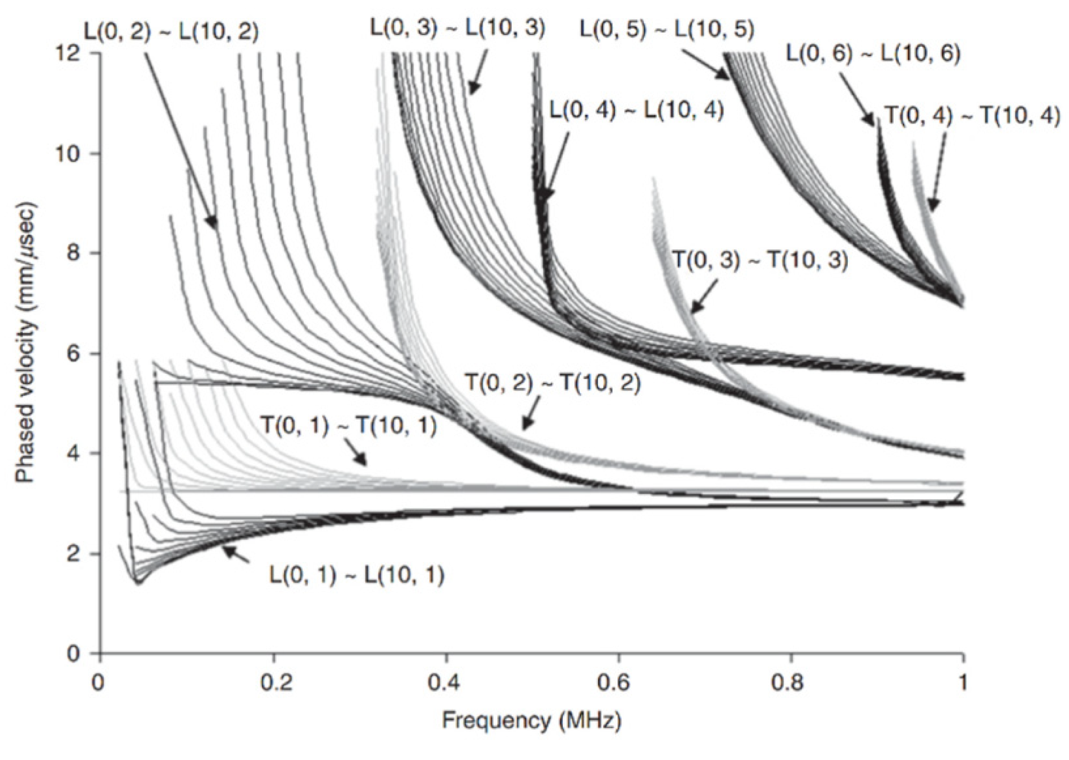
Figure 2.
Schematic diagram of ultrasonic-guided wave non-destructive testing technology for pipelines.
Figure 2.
Schematic diagram of ultrasonic-guided wave non-destructive testing technology for pipelines.
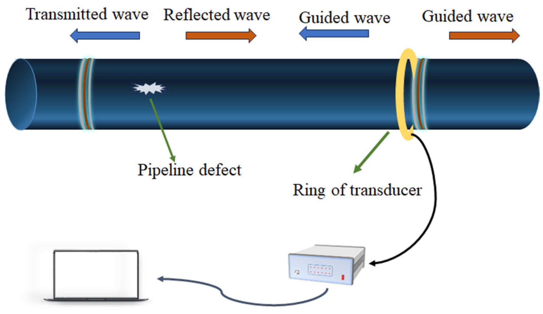
Figure 3.
Guided wave phase velocity dispersion curves in a steel plate: (a) Lamb modes and (b) shear horizontal (SH) modes [25].
Figure 3.
Guided wave phase velocity dispersion curves in a steel plate: (a) Lamb modes and (b) shear horizontal (SH) modes [25].

Figure 4.
Normalized displacement of wave modes in a 9-millimeter steel plate at 1 MHZ [7].
Figure 4.
Normalized displacement of wave modes in a 9-millimeter steel plate at 1 MHZ [7].

Figure 5.
Simulated B-scan images capturing the propagation of direct waves and spiral waves in the presence of circular defects with varying diameters and depths are presented. The B-scan images portray both direct waves and spiral waves (a,c,e,g) alongside specifically chosen spiral waves and corrected spiral waves (b,d,f,h) for defects of different dimensions: (a,b)—30 mm (depth 25%), (c,d)—30 mm (75%), (e,f)—40 mm (25%), and (g,h)—60 mm (25%). The dashed lines indicate the phase delay values of the signal amplitude peaks for spiral waves [128].

Figure 6.
Complete process of pipeline SHM.
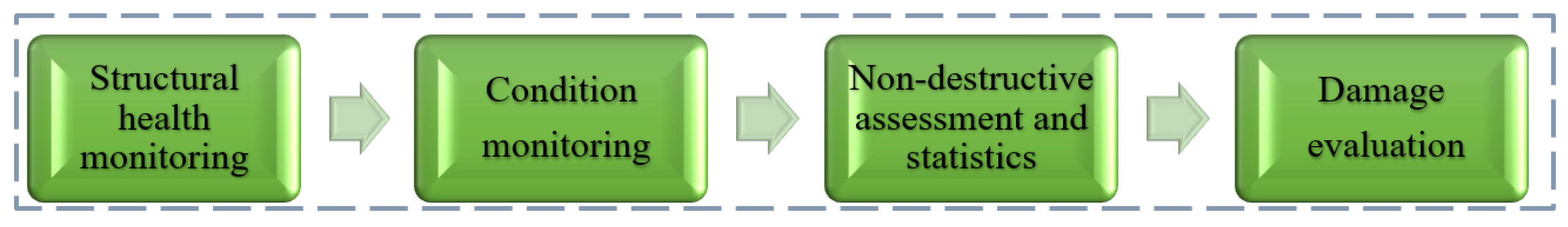

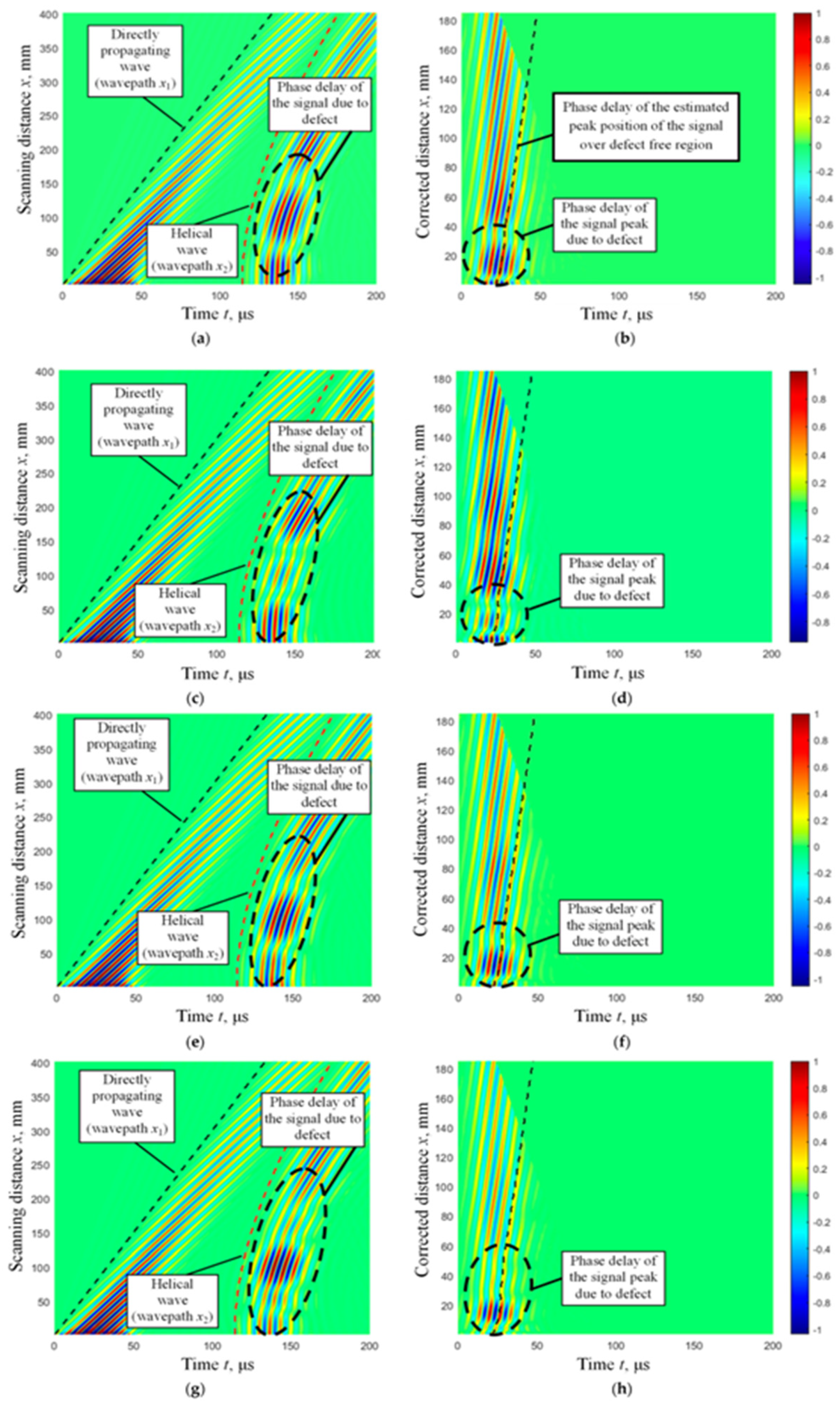
Table 1.
GW detection technology of pipeline corrosion based on partial transducer.
| Different Types of GW Transducers | Guided Wave Mode and Type | A Brief Introduction of the Research Content | Defect Type |
|---|---|---|---|
| Piezoelectric transducers (PZT) | L (0, 1) and L (0, 2) F (1, 1), F (1, 2), and F (1, 3) |
| Corrosion and notch-type defects |
| Higher-order circumferential | The 2D FE model using ABAQUS® verified that the system can detect defects as small as 1.5 mm in diameter and 25% of the penetrating wall thickness [87]. |
| |
| Phased array transducers (PA) | Circumferential GWs |
|
|
| L (0, 1) and L (0, 2) | Three-dimensional and two-dimensional finite-element simulation analysis was employed to study the reflection of guided waves (GWs) from non-axisymmetric and axisymmetric corrosion defects [86]. | Non-axisymmetric and axisymmetric corrosion defects | |
| T (m, 1) and L (m, 2) |
|
|
Table 2.
Lamb wave and shear horizontal wave modes in pipeline defect detection.
| Phase Velocity Dispersion Curves of Guided Waves in Steel Plate | Frequency-Thickness | Key Information | Partial Scope of Application | Defect Type | See for Details | |
|---|---|---|---|---|---|---|
| Lamb modes | S0 | 1 MHZ-mm 1.5 MHZ-mm |
|
|
| Khalili et al. [25] |
| A1 | 20 MHZ-mm |
|
| severe, sharp, pitting-type defects | Balasubramaniam et al. [123,124] and Khalili et al. [121] | |
| Shear horizontal (SH) modes | SH0 | 2.5 MHz-mm | Not affected by non-viscous liquid loads on the structure. Non-dispersive inspection can be conducted in the fundamental SH0 mode. | For pipes with relatively thin walls (<15 mm), EMATs are employed to excite SH0 and SH1 modes. |
| Cawley et al. [33,34,35,36,37] |
| SH1 | 3 MHz-mm | The mode exhibits dispersion characteristics around 3 MHz·mm and demonstrates a mode shape with high surface energy. | Advantageous for short-range detection and very shallow crack-like defects. | SH1 mode to very shallow (<10% thickness loss) crack-like defects | Howard et al. [125] | |
Disclaimer/Publisher’s Note: The statements, opinions and data contained in all publications are solely those of the individual author(s) and contributor(s) and not of MDPI and/or the editor(s). MDPI and/or the editor(s) disclaim responsibility for any injury to people or property resulting from any ideas, methods, instructions or products referred to in the content. |
© 2024 by the authors. Licensee MDPI, Basel, Switzerland. This article is an open access article distributed under the terms and conditions of the Creative Commons Attribution (CC BY) license (https://creativecommons.org/licenses/by/4.0/).
Share and Cite
MDPI and ACS Style
Lyu, F.; Zhou, X.; Ding, Z.; Qiao, X.; Song, D. Application Research of Ultrasonic-Guided Wave Technology in Pipeline Corrosion Defect Detection: A Review. Coatings 2024, 14, 358. https://doi.org/10.3390/coatings14030358
AMA Style
Lyu F, Zhou X, Ding Z, Qiao X, Song D. Application Research of Ultrasonic-Guided Wave Technology in Pipeline Corrosion Defect Detection: A Review. Coatings. 2024; 14(3):358. https://doi.org/10.3390/coatings14030358
Chicago/Turabian StyleLyu, Feng, Xinyue Zhou, Zheng Ding, Xinglong Qiao, and Dan Song. 2024. "Application Research of Ultrasonic-Guided Wave Technology in Pipeline Corrosion Defect Detection: A Review" Coatings 14, no. 3: 358. https://doi.org/10.3390/coatings14030358
Note that from the first issue of 2016, this journal uses article numbers instead of page numbers. See further details here.