
In Situ Synthesis of an Epoxy Resin Microwave Absorption Coating with Anti-Ultraviolet Aging Effects

1
National Energy Group Ningxia Coal Industry Co., Ltd., Yinchuan 750001, China
2
School of Materials Science and Engineering, Xiangtan University, Xiangtan 411105, China
3
Hunan Bangzer Technology Co., Ltd., Xiangtan 411100, China
*
Authors to whom correspondence should be addressed.
Coatings 2024, 14(4), 514; https://doi.org/10.3390/coatings14040514
Submission received: 29 March 2024
/
Revised: 17 April 2024
/
Accepted: 18 April 2024
/
Published: 20 April 2024
(This article belongs to the Special Issue Advanced Polymeric Materials and Coatings: Synthesis, Properties and Applications)
Abstract
:A nanoparticle-anchored three-dimensional microsphere flower-structured layered double hydroxide (LDH) material with Fe3O4 particles was successfully prepared using simple hydrothermal and hot solvent methods. Micro-nanostructured Fe3O4@LDHs (SLF) composites balance microwave absorption, corrosion protection, and UV aging resistance. The minimum reflection loss value of SLF is −35.75 dB at 14.16 GHz, when the absorber thickness is 8 mm, and the absorption bandwidth at this frequency is up to 2.56 GHz for RL values less than −10 dB, while the LL is only 1 GHz. The SLF /EP coating has not only excellent microwave absorption performance but also excellent corrosion and UV aging resistance performance. The coating still has some anti-corrosion effect after 10 d of immersion. This work is intended as a reference for the development of new coatings with excellent microwave absorption properties as well as corrosion and UV aging resistance for wind turbine tower barrels (seaside wind power generation equipment) surfaces.
1. Introduction
Wind turbine tower barrels (wind power generation equipment) serving in seaside high-salt and strong UV environments strongly reflect electromagnetic waves, which greatly affect the normal performance of military equipment and causes serious electromagnetic pollution, which may lead to signal saturation or even signal burnout for radar communication equipment receivers. With increases in sea breeze, the impact on military equipment becomes even more obvious, but it has been found that coating wind turbine tower barrels with microwave absorption (MA) materials significantly reduces electromagnetic wave reflectivity, thereby reducing excessive interference with the equipment [1,2,3,4,5]. The direct dismantling of wind power projects can involve the loss of assets; however, conventional MA materials face a series of problems, such as corrosion in the marine environment. Therefore, the development of composite coating materials with MA properties, corrosion resistance, and UV aging resistance is urgent. Pure epoxy resin (EP) coatings are widely used because of their excellent chemical resistance, low shrinkage, strong adhesion to various substrates, etc.; however, they can be easily damaged by corrosive media and have poor UV aging resistance, which limits their further application [6,7]. Therefore, improving the protective performance of EP in complex environments is of great significance.
Numerous studies have shown that doping nanofillers into EP can improve corrosion protection and MA properties. For example, layered double hydroxides (LDHs), graphene oxide, and hexagonal boron nitride have been widely used to enhance the corrosion resistance and MA properties of EP [8,9,10,11,12,13]. Nanofillers can additionally fill the internal voids of EP and form a “labyrinth effect” [14]. LDHs, also known as 2D hydrotalcites, have similar properties to 2D layered materials, such as hexagonal boron nitride, and their layered structures can impede the penetration of electrolytes into EP, making them a promising candidate for corrosion protection [15]. Meanwhile, the application of LDHs for MA is limited by their constant morphology and impedance imbalance [16]. Therefore, the applications of common 2D lamellar-structured LDHs (LL) for corrosion protection and MA are more limited, and their performance does not meet our needs. Many studies have found that the geometrical morphology of the material plays a key role in enhancing MA performance [17,18,19]; thus, in our previous study, we prepared spherical flower-structured LDHs (SL) through a simple hydrothermal method using citric acid regulation, which forms a large specific surface area and cause numerous multiple reflections [20]. The single SL demonstrates limited enhancement of the anti-corrosion and MA properties of the composite coatings.
Currently, ferrite-based materials are widely used as MA materials due to their proper MA capability; for example, Fe3O4 particles can demonstrate not only a polarization effect, in terms of dielectric properties, but also a magnetic loss effect for microwave absorption, which is considered most likely to be the ideal absorbing material within the GHz frequency range [21,22]. Meanwhile, Fe3O4 has been applied in the fields of anticorrosion and UV shielding due to its easy modification [23,24]; however, Fe3O4 is susceptible to a lot of agglomerations, which prevents its properties from being fully utilized. Therefore, we obtained Fe3O4@LDHs (SLF) with a 0D/3D structure by anchoring Fe3O4 nanoparticles on folded nanosheets of SL. This structure first enhances the electron transfer between LDHs and Fe3O4; second, the many Fe3O4 nanoparticles that lie flat on the large specific surface area of the LDHs enhance the absorption of electromagnetic waves. Therefore, we combined SLF with EP to prepare SLF/EP composite coating materials, and surprisingly, we also found that the prepared composite coating materials have certain UV aging properties.
In this work, in order to extend the application of EP in complex environments, spherical-structured LDHs (SL) were prepared using a simple hydrothermal method, and then, SLF composites were prepared by immobilizing Fe3O4 on spherical-structured LDHs. The SLF/EP coatings exhibited excellent MA, corrosion protection, and UV resistance.
2. Experimental Section
The materials, characterization, and performance test details are provided in the Supporting Information.
2.1. Synthesis of the SL and SLF Composites
First, 1.02 g of Mg(NO3)2•6H2O, 0.75 g of Al(NO3)3•9H2O, 1 g of urea, and 0.23 g of citric acid (CA) were completely dissolved in 60 mL of a water–ethanol solution. The mixture was moved to a stainless steel autoclave lined with Teflon, stirred for 30 min, and then adjusted to 160 °C for 24 h. After the solution cooled naturally to room temperature, the mixture was centrifugally reacted, washed three times at 5000 rpm, and then dried at 60 °C for 12 h to form the final products, denoted as SL. LL was prepared without the addition of CA. Then, according to the in situ growth method, 0.1 g of SL was mixed with 1.72 mmol of FeCl3•6H2O and 0.86 mmol of FeCl2•4H2O, dissolved in 60 mL of deionized water, reacted, and stirred at 80 °C for 2 h under the protection of nitrogen; the products were thereafter denoted as SLF composites.
2.2. Preparation of SLF/EP Composite Coatings
First, the Q235 steel substrate was mechanically polished with 400-, 800-, and 1200-grade sandpaper; cleaned with ethanol; and dried before coating. The composite coatings were prepared according to the following procedure: 0.12 g of SLF was dispersed into 6 g of epoxy resin, ultrasonicated for 30 min, and mechanically stirred for 1 h. Subsequently, 2 g of P54 curing agent was added, and after the mixture was vigorously stirred for 10 min, the composite material was uniformly sprayed onto the Q235 steel surface. The samples were left at room temperature for 30 min, transferred to an oven (60 °C, 24 h) to achieve complete curing, and subsequently labeled as SLF/EP. Pure EP coatings and coatings containing LL, SL, and SLF were also prepared similarly for comparison; they were denoted as EP, LL/EP, and SL/EP, respectively.
3. Results and Discussion
Figure 1 shows the synthesis schedule of the samples. First, LL and SL samples were synthesized using a one-step hydrothermal method, and SLF was obtained via the in situ growth of Fe3O4 on the surface of SL nanosheets by introducing an iron source.
3.1. Morphological and Structural Characterization
The crystal phase and structural information of LL, SL, and SLF samples were analyzed using XRD, and the results are depicted in Figure 2. The LL sample exhibits peaks denoted by ☆ appeared at 11.6°, 23.4°, 34.8°, 39.4°, 47.0°, and 61.1°, indexed to (003), (006), (012), (015), (018), and (110) planes of characteristic LDHs (JCPDS 35-0964), respectively [25]. However, the characteristic peaks, denoted by ✯, corresponding to the (003), (006), (012), (015), and (018) crystal planes of the SL sample shifted due to the addition of citric acid (CA). The XRD spectrum of the SL sample shows basic reflection at 2y = 7.2, demonstrating a periodic layered structure. Through the calculation formula of crystal plane spacing, it can be found that this result is very consistent with the size of CA macromolecules [26], which also laterally proves the successful preparation of spherical flower-structured LDHs (SL). The SLF sample shows the typical diffraction reflection of (220), (311), (400), (422), (511), and (400), which can be indexed as the characteristic peaks of Fe3O4 [27]. And the characteristic peaks are denoted by ★. The characteristic peaks of the SL only appeared at (009), which also indicated that the Fe3O4 nanoparticles had encapsulated the SL, obscuring the other original characteristic peaks of the SL and proving the successful preparation of SLF.
Figure 3 shows the FTIR results of the LL, SL, and SLF samples. The LL showed a broad peak around 3456 cm−1, which could be attributed to the stretching vibration of the water molecules between the layers, the hydroxyl (-OH) of the laminate, and the water of the crystal. The sharp peak appearing at 1355 cm−1 is attributed to the N-O bond of NO3- in nitrate. The two peaks at 687 cm−1 and 448 cm−1 are derived from the Mg-O and Al-O bonds in the hydrotalcite, respectively [28]. Combined with the above XRD analyses, the successful preparation of the LL sample was demonstrated. As far as the FT-IR spectra of SL are concerned, the band at 1575 cm−1 was designated as the vibrational peak of the carbon skeleton (C-C). The peaks of 1393 cm−1 was assigned to C=O in the carboxylic acid groups, suggesting that citric acid had succeeded in replacing NO3− [29]. Additionally, Mg-O and Al-O bonds can be found within the hydrotalcite in question, proving the successful preparation of SL. The absorption band of SLF at 576 cm−1 is related to Fe-O bonding [30]. Moreover, we can clearly find the C-C, C=O, Mg-O, and Al-O bonds in SL in the spectrogram of SLF, which, combined with the results of XRD analysis, proves the successful synthesis of SLF.
An XPS analysis was performed on all elements present in the SLF sample to gain insight into the chemical states and compositions of the elements. The survey and high resolution XPS spectra of Mg 1s, Al 2p, C 1s, O 1s, and Fe 2p are shown in Figure 4. The primary elements of Mg, Al, O, C, and Fe in SLF are further confirmed in the XPS survey spectra (Figure 4a). The high-resolution XPS spectra of Mg 1s and Al 2p show only one characteristic peak at 1304.1 and 74.4 eV (Figure 4b,c), attributed to Mg-OH and Al-OH, respectively, thus validating the preparation of MgAl-LDHs [31]. The high-resolution C 1s peak of SLF can be decomposed into three characteristic peaks centered at about 284.8 eV, 286.6 eV, and 288.7 eV, corresponding to C-C/C=C, C-O, and C=O, respectively (Figure 4d) [32]. The O1s spectrum of SLF can be fitted to four peaks centered at 530.0 eV, 531.0 eV, 532.0 eV, and 532.7 eV, which correspond to Fe-O, COOH, C=O, and C-O groups, respectively (Figure 4e) [33]. These results further evidence the presence of CA in S-LDHs. The peaks at about 710.6 and 724.1 eV in the Fe 2p spectrum of SLF are attributed to the binding energies of Fe 2p3/2 and Fe 2p1/2, respectively [34]. Meanwhile, those of Fe 2p3/2 can be categorized into two different peaks, Fe3+ and Fe2+, suggesting multiple possibilities (Figure 4f) but also demonstrating the presence of Fe3O4 and Fe-O in SLF [35].
As seen in Figure 5a, the LL grown without CA guidance has a hexagonal nanosheet structure, whereas the SL grown under CA guidance has a three-dimensional microsphere flower structure, with numerous folded nanosheets distributed on the surface of the microspheres, as shown in Figure 5b. It can be seen from Figure 5c that many Fe3O4 particles, with sizes of about tens of nanometers, were grown in situ on the SLF surface. From the transmission electron microscopy images of SL and SLF (Figure 5d,e [20]), it can be seen that a significant amount of Fe3O4 encapsulates the spherulitic structure of the SL, whereas the results of Figure 5f–i reveal the presence of the elements Fe, O, Mg, and Al. The distribution of the Fe element exhibits a clear fringe aggregation, which verifies the structural composition of the SLF.
3.2. MA Performance
We obtained the electromagnetic parameters and reflection loss data regarding the LL and SL samples used for the follow-up in our previous work [20]. The characteristics of the electromagnetic field include complex permittivity () and complex permeability ). It is well known that after a microwave enters the microwave-absorbing materials, the materials provide dielectric loss and magnetic loss to consume the energy of the microwave. Therefore, the dielectric properties and magnetic properties of the materials together affect the MA performance of the materials. The four parameters ε′, ε″, μ′, and μ″ represent the dielectric and magnetic properties of the materials. The actual components of permittivity (ε′) and magnetic permeability (μ′) were used to indicate the capabilities to store electric and magnetic energy. The fictitious components of permittivity (ε″) and magnetic permeability (μ″) were used to represent electrical dissipation and magnetic loss, respectively. The dielectric loss tangent () and magnetic loss tangent () were used to express the loss capacity of electromagnetic wave energy [36,37]. As shown in Figure 6a,b, SLF clearly possesses the best dielectric storage of electrical energy and dielectric loss capability. This is mainly attributed to Fe3O4 nanoparticles. Figure 6e shows the dielectric loss tangent of SLF. It can be seen that the variation trend largely agrees with the value of the dielectric constant. The μ′ and μ″ of the material, as the effects of frequency, are shown in Figure 6c,d, where it can be observed that the variation trend is basically consistent with the dielectric constant. The μ′ value of the samples after the addition of Fe3O4 appeared to be less than 1, and there were multiple resonance peaks, which could be due to eddy current loss and ferromagnetic resonance [38]; μ″ increases in the low-frequency region and decreases in the high-frequency region for SLF compared to the sample before the addition of Fe3O4. The material as a whole shows a trend that continually decreases with increasing frequency. The calculated magnetic loss tangent was shown in Figure 6f, following the same trend as the magnetic permeability, suggesting that composite Fe3O4 particles lead to an increase in the magnetic loss capability of the material.
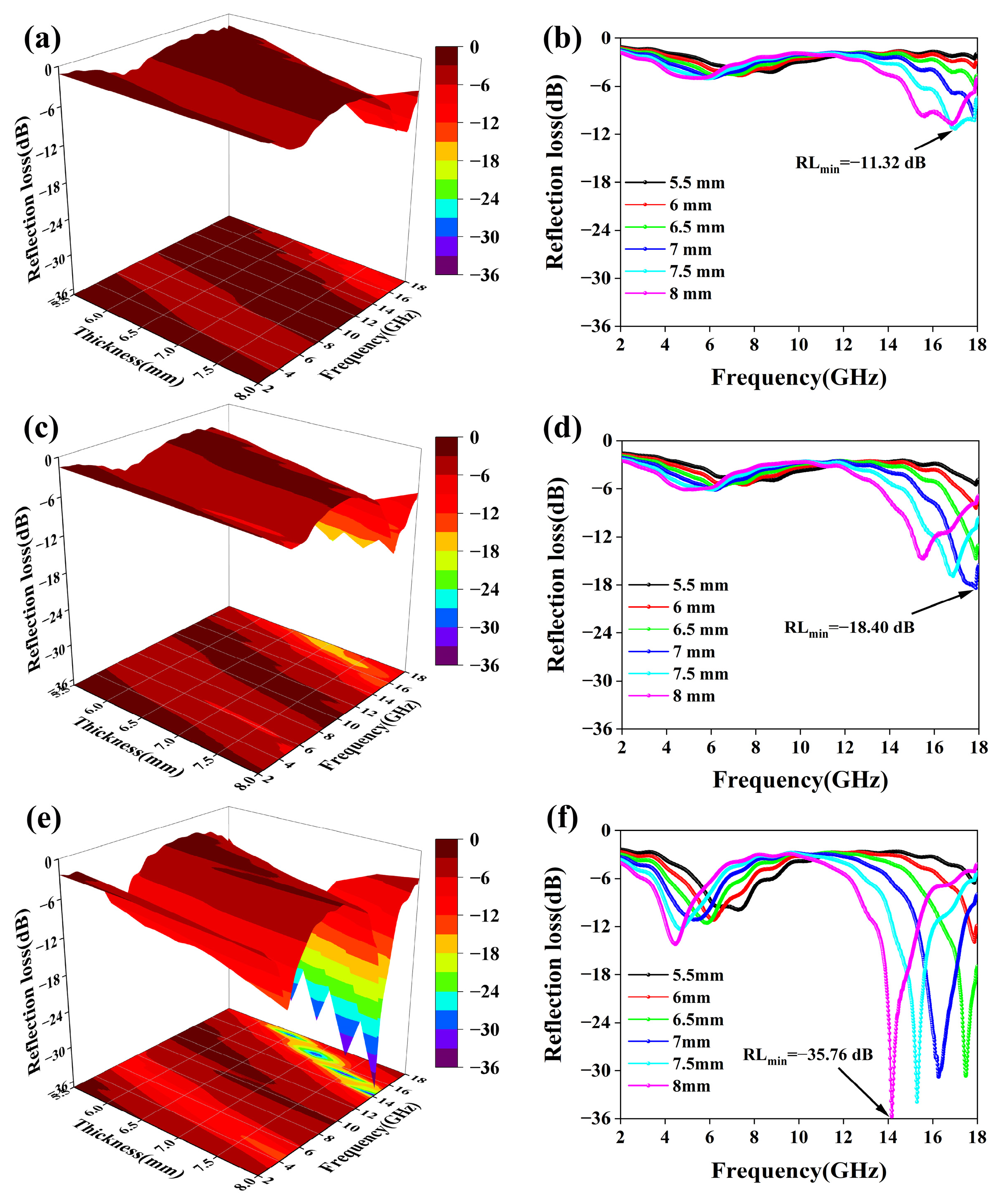
In general, reflection loss (RL) is used to evaluate the MA performance of a material. RL ≤ −10 dB was defined as effective absorption. According to transmission line theory and the electromagnetic parameters measured in the 2–18 GHz range, the corresponding RL was calculated according to the following equations [39]:
Figure 7 shows the 3D and 2D RL values for the LL, SL, and SLF samples at frequencies from 2 to 18 GHz. As shown in Figure 7a,b, the LL sample has an RLmin of −11.32 dB at 17.00 GHz, a thickness of 7.5 mm, and an EAB of only 1 GHz. In contrast, the 3D spherical flower-structured SL sample has an RLmin of −18.40 dB at 17.87 GHz with a thickness of 7 mm and an EAB of 2.5 GHz (Figure 7c,d). Obviously, the three-dimensional ball-and-flower structure improved MA performance. Meanwhile, the SLF sample after the addition of Fe3O4 has an RLmin of −35.75 dB at 14.16 GHz, a thickness of 8 mm, and an EAB of 2.56 GHz. From Figure 7e,f, it can be found that the introduction of Fe3O4 led to a shift in the optimum frequency of the composites towards lower frequencies, which extends their range of applications and improves the RLmin. As shown in Table S1, the MA performance of the prepared SLF sample is better than that of other composites that have been studied to date.
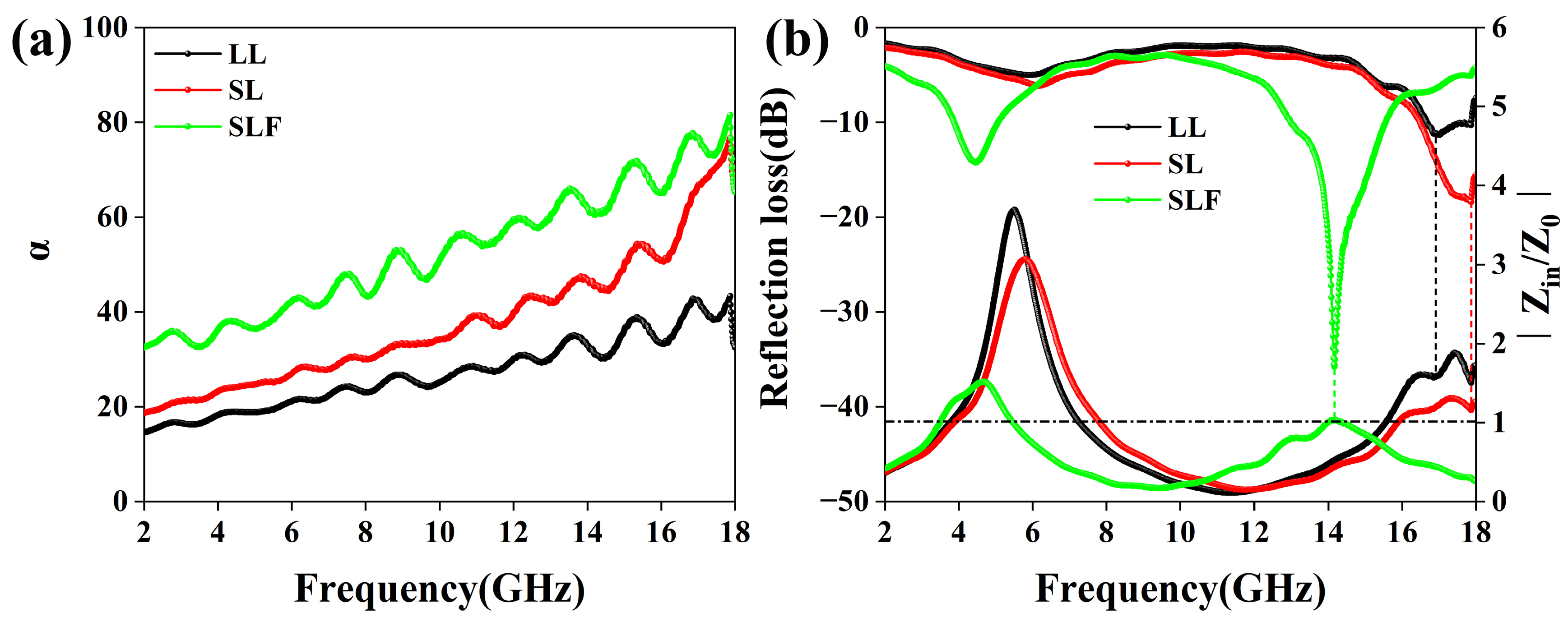
Attenuation capability and impedance matching are two key factors that determine the absorption properties of MA materials [40]. The energy conversion rate depends on the attenuation capability of the electromagnetic wave, expressed as the attenuation constant (α) when the incident electromagnetic wave enters the absorbing material and is calculated using Equation (3). The α curves of all of the samples are shown in Figure 8a. Obviously, the SLF sample has a high α value, which is an indication that it has strong attenuation capability for the incident electromagnetic wave, which is in line with its excellent MA performance. Impedance-matching capability determines the frequency range and amount of incident electromagnetic waves that enter a material, evaluated from the ratio of input impedance to characteristic impedance using transmission line theory. The input impedance of an ideal MA material is the same as its impedance in free space, which means that the value is equal to 1. The Z value calculation formula is shown in Equation (4). As shown in Figure 8b, the impedance matching ratio of the SLF sample is closer to 1 than those of the other samples, indicating that it has the optimal impedance-matching characteristics. This is further evidence that SLF demonstrates optimal MA performance.
On the basis of the above evidence, we propose an MA mechanism for the SLF materials, as shown in Figure 9. First, the three-dimensional spherical flower structure creates more interfaces and generates significant interfacial polarization, which leads to more dielectric and magnetic losses [41]. Second, the resulting high specific surface area, along with the numerous pores and spaces, provides multiple reflection and scattering channels, which further enhance the attenuation of incident waves [42]; in addition, the generated three-dimensional interconnected conductive network can provide more conductive paths for electron transport [43]. Third, Fe3O4 anchored on the surface of 3D spherical flower-structured LDHs leads to the existence of multiple heterogeneous interfaces, including those between LDHs and Fe3O4 nanoparticles, those between LDHs and paraffin, and those between paraffin and air, which greatly improves the structure’s interfacial polarization capability. The main factors that improve the magnetic loss of MA are the eddy current effect and natural resonance.
3.3. Anti-Corrosion Performance
Bode and Nyquist plots of EP and composite coatings at different immersion times are shown in Figure 10 for examination of the EIS trends of composite coatings at different immersion times. The EIS results were fitted using Zsimdemo 3.30d software, and the parameters obtained are shown in Table S2; all coatings are at the mid-corrosion stage, and the curves adhere to the fitted circuit Rs(CPEc(Rc(CPEdlRct))), shown in Figure S1 [44]. Rs is the solution resistance, CPEc is the interfacial capacitance between the solution and the coating, Rc is the resistance of the impermeable coating, CPEdl is the interfacial capacitance between the corrosive solution intrusion and the non-intrusion, Rct is the resistance of the coating not yet infiltrated by the corrosive liquid, and Zf is the value of the impedance film. On the first day of immersion, the SLF/EP composite coating showed the highest impedance, with a Zf=0.01Hz value of 6.947 × 10¹⁰ Ω•cm2, which was much higher than that of the pure EP coating, with Zf=0.01Hz (9.364 × 10⁹ Ω•cm2).
The order of resistive arc radius for different coatings is SL/EP > LL/EP > EP, as shown in Figure 10a,c,e. The resistance to corrosion reaction is reflected in the magnitude of the resistive arc radius, suggesting that the addition of fillers to pure epoxy coatings can enhance the effects of the coatings on the substrate to varying extents. In general, the barrier performance parameter of the coating can be defined as the impedance modulus at the lowest frequency (Zf = 0.01 Hz) in the Bode plot. The Zf = 0.01 Hz value of pure EP decreased sharply to 1.112 × 10⁷ Ω•cm2 after 7 d of immersion (Figure 10b) because pure EP has many microscopic pores, which means corrosive media can more easily diffuse into the coating/substrate surface. For the LL/EP and SL/EP coatings, the Zf = 0.01 Hz values were 1.794 × 10⁸ Ω•cm2 and 4.191 × 10⁸ Ω•cm2 after 7 d of immersion, respectively, both an order of magnitude higher than that of the pure epoxy resin, which was attributed to the effects of the fillers on the EP coatings, as the micropores possess a distinct filling characteristic. The evidence suggests that LL and SL fillers can enhance the corrosion resistance of EP coatings, yet the level of the improvement is restricted.
As shown in Figure 10e,f, the SLF/EP composite coatings started to enter the middle stage of corrosion only after 10 d of immersion, while the Zf value was still 6.988 × 10⁹ Ω•cm2. The performance of the SLF/EP composite is far superior to that of pure EP, and the corrosion rate of the coating is reduced dramatically.
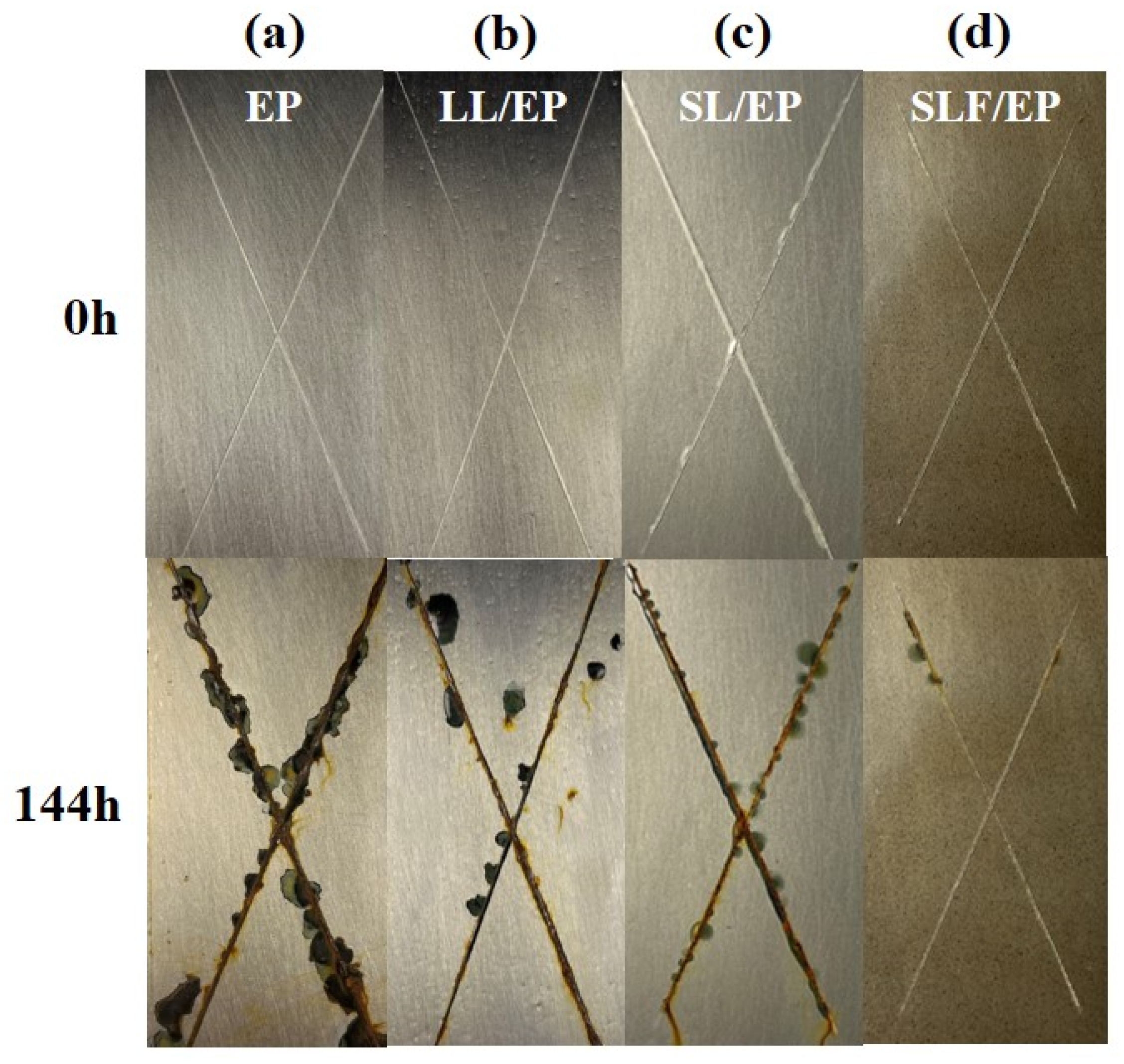
All of the created coatings with simulated flaws were placed in a salt spray furnace to test their corrosion resistance. Figure 11 shows digital photographs of the coatings after 144 h of exposure. It is evident that the EP coatings exhibited significant rust in their scratched areas and significant pitting in their unscratched areas. This can result from poor barrier performance, allowing for corrosive media to spread along scratch lines. As for the LL/EP coating, poor dispersion can be clearly seen, with many small holes appearing on the surface of the coating. At the same time, some corrosion products accumulated at the scratches, and pitting corrosion also appeared on the coating surface, but the corrosion phenomenon was improved compared with that of pure EP corrosion. The surface corrosion of the SL/EP coatings was reduced compared with the LL/EP coatings, and the surface of the coatings was as smooth as that of the pure EP coatings, which proved that the citric acid-induced formation of the 3D globular flower structure could improve the dispersion of the coatings to a certain extent, enhancing the corrosion resistance of the coatings. However, on the surface of the SLF/EP coating, no obvious pitting corrosion was observed. Further, demonstrating its excellent corrosion protection, the corrosion products at the scratches were the lowest of all of the coatings, findings which are in general agreement with those of the EIS assessment.
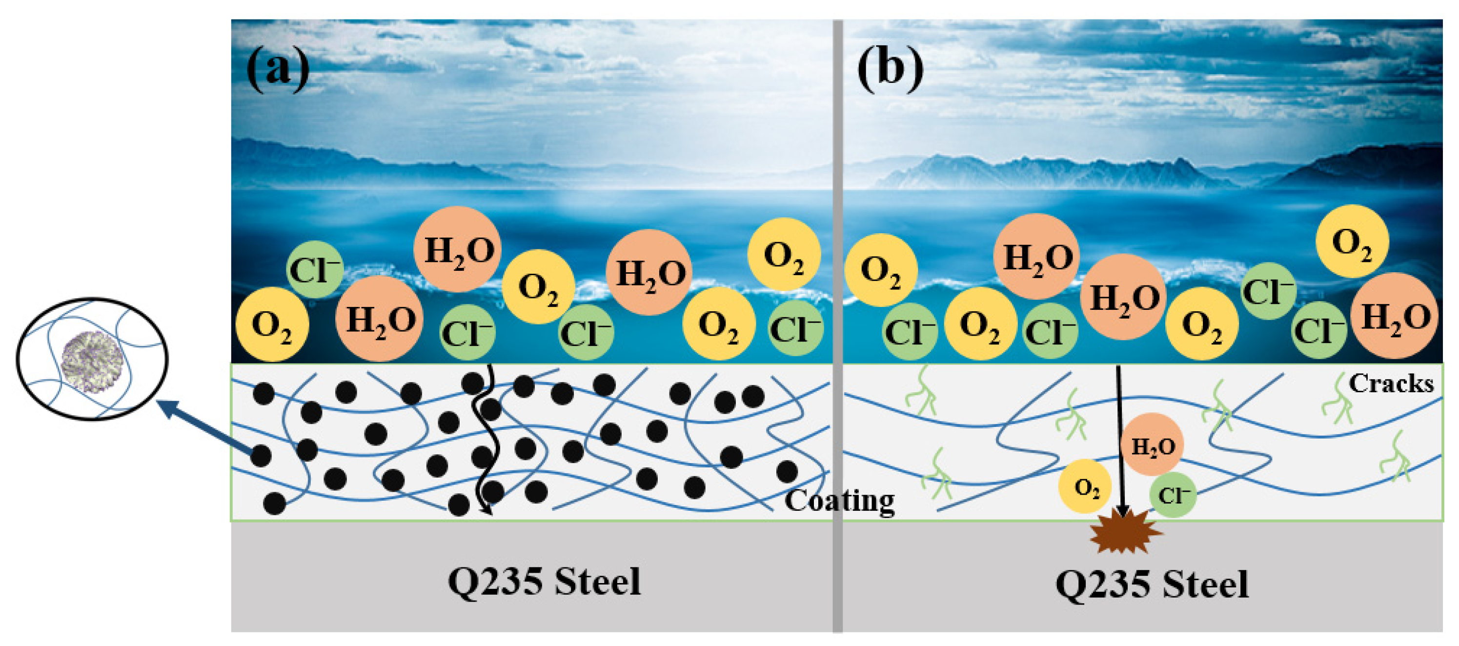
Regarding pure epoxy coatings (Figure 12b), corrosive electrolytes can easily enter through the large number of micropores in solvent-based EP coatings, and the coatings do not provide any barrier effect. However, the addition of SLF composites significantly improved the corrosion resistance of the coatings (Figure 12a). The protective mechanism of SLF/EP is as follows: the nano-Fe3O4, anchored on the surface of 3D microsphere flower LDHs, formed a micro-nanostructure that could fill the defects and micropores in the EP coatings in large quantities [45]; therefore, more flaws and micropores in the EP coating can be reduced by the highly scattered SLF micro-nanostructures. As a result, the coating’s permeability is decreased, and the “labyrinth effect” created by the SLF can increase the diffusion path for corrosive electrolytes to penetrate into the coating and the substrate, thus increasing the barrier effect. Finally, nano-Fe3O4 also has inherent corrosion inhibition properties [46].
3.4. Anti-UV Aging Performance
The absorbance of the samples is shown in Figure 13a. Pure EP exhibited low UV absorption throughout the wavelength range. The UV absorption of the composite coatings was slightly improved when LL and SL were added to EP. However, when SLF filler was introduced, the UV absorption of the composite coating showed a significant enhancement. The results showed that the UV aging resistance of the LDHs was significantly improved by Fe3O4. The FT-IR of the composite coatings was analyzed after exposure to UV irradiation for 24 h, as shown in Figure 13b. The degradation samples after UV irradiation were mainly characterized by the large production of carbonyl groups [47]. It can be seen from the figure that the carbonyl peak of the SLF/EP sample has a significant decrease compared with that of the pure EP. Meanwhile the other groups in the infrared profile are less changed compared to the sample before irradiation. This is consistent with the conclusions obtained from UV absorption. Optical photographs of the samples showed the same pattern, with clear yellowing of pure EP, LL/EP, and SL/EP as a result of carbonyl production (Figure S2). Accordingly, SLF has the effect of enhancing the UV aging resistance of EP. This is attributed to the LDHs as well as Fe3O4 having the anti-ultraviolet aging characteristics; SL formed by the microsphere structure provides Fe3O4 more nucleation sites so that the Fe3O4 nanoparticles receive a wider range of unfolding, resulting in the improvement of the anti-ultraviolet aging ability of the SLF. This effect is similar to that of its MA mechanism, in that ultraviolet light and microwave are both waves, with their only difference being their frequency ranges.
3.5. Wear Resistance
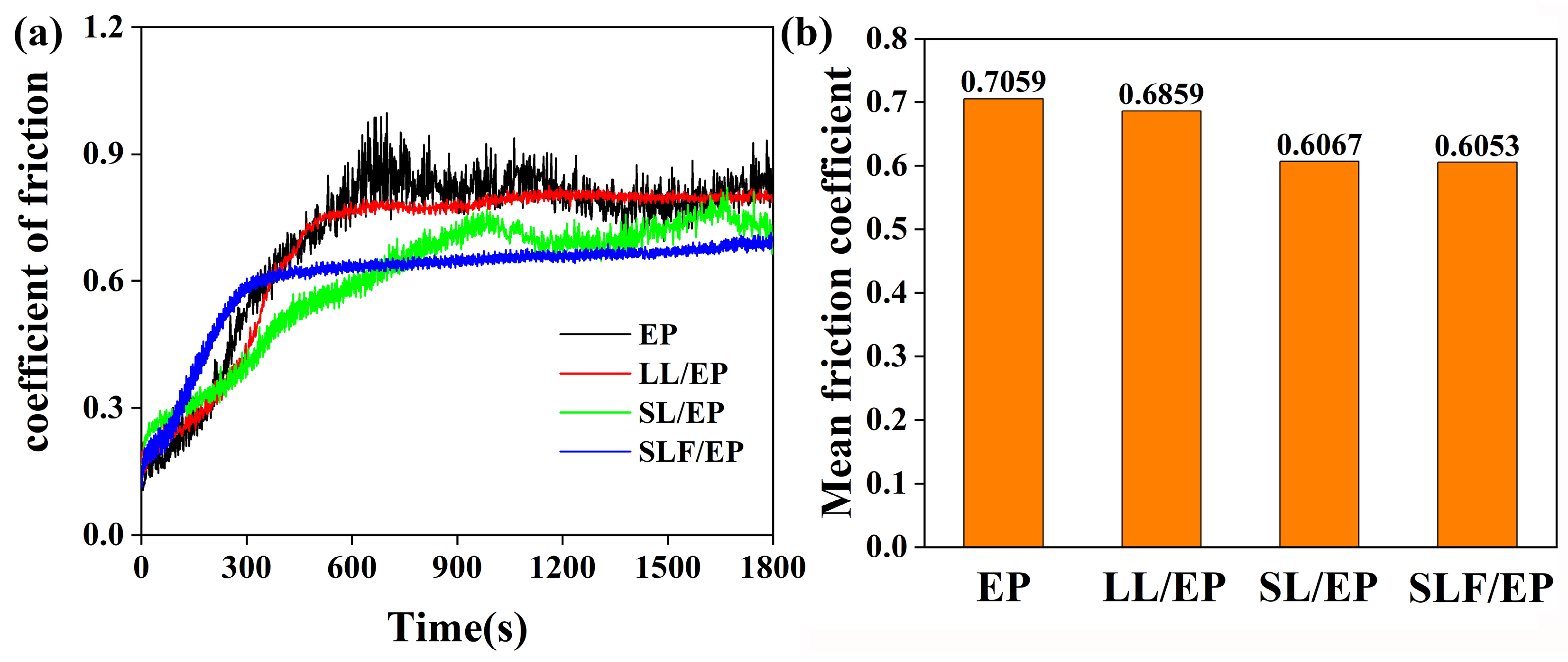
The coefficients of friction and the corresponding mean friction coefficients of the sample coatings at 2 N of load are shown in Figure 14. Figure 14a shows the dynamic curves of the friction coefficients for all four coatings. Since the prepared coatings are not completely flat on their surfaces, all of the coated samples show a short “saturation” phase at the beginning of the wear process, during which the friction coefficient increases with time [48]. As the wear process continues, we find that the friction coefficient of the pure EP coating shows a short period of sharp increase and significant oscillations and that its dynamic friction coefficient is the most unstable compared to the other coatings due to the fact that the pure EP coating itself has micropores, and its coefficient of friction will also have a period of unstable increase. After the addition of LL and SL, the friction coefficients of the composite coatings have some decreases compared with the pure EP coatings and are relatively stable due to the fact that the addition of LDHs fills the micropores of the pure EP coatings to a certain extent, which improves the mechanical properties of the overall structure. However, after the addition of SLF, it can be seen that the coefficient of friction has a rapid increase in the early stage and then maintains an extremely smooth friction behavior; throughout the friction process, there is no major fluctuation phenomenon, thus demonstrating optimal stability. Figure 14b shows the corresponding mean friction coefficient of all four coatings. We can see that the average coefficient of friction for the pure EP coating is greater, at 0.7059, while that for the SLF/EP coating is 0.6053, the lowest obtained value. In conclusion, the SLF/EP coating has the best wear resistance, likely related to the introduction of Fe3O4, which enhances the hardness of the SLF composite, which, in turn, enhances the hardness of the coating, making it more wear resistant.
4. Conclusions
For this study, a novel micro-nanostructure with excellent MA performance was prepared by anchoring Fe3O4 nanoparticles on the surface of 3D microsphere flower-structured LDHs (SLF). Meanwhile, we found that the SLF composites demonstrate excellent MA performance in the high-frequency range (12–18 GHz) and are therefore valuable for applications in fields where electromagnetic pollution exists. Furthermore, the introduction of SLF greatly improves the anticorrosive properties of the EP coating as well as its UV aging resistance. As a result, we believe that our work will encourage the development of new coatings with excellent MA, corrosion resistance, and UV aging resistance and provide a reference for further research on surface coatings for wind turbine tower barrels. Meanwhile, the coatings also have potential value in applications such as the electronic communication equipment for marine warships and stealth technology for submarines.
Supplementary Materials
The following supporting information can be downloaded at: https://www.mdpi.com/article/10.3390/coatings14040514/s1, Figure S1: Coating corrosion equivalent circuit diagram; Figure S2: Macroscopic picture of the samples before and after UV irradiation (from left to right, EP, LL/EP, SL/EP and SLF/EP coatings) [49]. Table S1: MA properties of SLF and other previously studied composites [50,51,52,53,54,55]; Table S2: Electrochemical impedance spectroscopy data of neat epoxy and nanocomposite coatings.
Author Contributions
Conceptualization, S.Y. and X.C.; methodology, X.C.; software, X.C.; validation, X.C., J.T.; formal analysis, S.Y.; investigation, A.Z.; resources, A.Z.; data curation, S.Y.; writing—original draft preparation, X.C.; writing—review and editing, J.T., X.C. All authors have read and agreed to the published version of the manuscript.
Funding
This work was supported in part by Ningdong Base Science and Technology Innovation Development Special Project (2019NDKJLX0008); High Technology Research and Development Program of Hunan Province of China (2022GK4038); Hunan Graduate Innovation Research Project (QL20220137).
Institutional Review Board Statement
Not applicable.
Informed Consent Statement
Not applicable.
Data Availability Statement
The data presented in this study are available upon request from the corresponding author. The data are not publicly available due to technical limitations.
Conflicts of Interest
Author Shujun Yan was employed by National Energy Group Ningxia Coal Industry Co., Ltd., and authors Xin Chen and Jun Tang were employed by Hunan Bangzer Technology Co., Ltd. The funders had no role in the design of the study; in the collection, analyses, or interpretation of data; in the writing of the manuscript; or in the decision to publish the results.
References
- Zhao, Z.; Lan, D.; Zhang, L.; Wu, H. A Flexible, Mechanically Strong, and Anti-Corrosion Electromagnetic Wave Absorption Composite Film with Periodic Electroconductive Patterns. Adv. Funct. Mater. 2021, 32, 2111045. [Google Scholar] [CrossRef]
- Yang, Y.; Xu, D.; Kong, L.; Qiao, J.; Li, B.; Ding, X.; Liu, J.; Liu, W.; Wang, F. Construction of Ni-Zn bimetal sulfides Heterostructured-hybrids for High-performance electromagnetic wave absorption. J. Colloid Interface Sci. 2022, 606, 1410–1420. [Google Scholar] [CrossRef] [PubMed]
- Wang, Y.; Gao, X.; Wu, X.; Zhang, W.; Luo, C.; Liu, P. Facile design of 3D hierarchical NiFe2O4/N-GN/ZnO composite as a high performance electromagnetic wave absorber. Chem. Eng. J. 2019, 375, 121942. [Google Scholar] [CrossRef]
- Bibi, M.; Abbas, S.; Ahmad, N.; Muhammad, B.; Iqbal, Z.; Rana, U.; Khan, S. Microwaves absorbing characteristics of metal ferrite/multiwall carbon nanotubes nanocomposites in X-band. Compos. Part B Eng. 2017, 114, 139–148. [Google Scholar] [CrossRef]
- Wei, S.; Chen, T.; Wang, Q.; Shi, Z.; Li, W.; Chen, S. Metal-organic framework derived hollow CoFe@C composites by the tunable chemical composition for efficient microwave absorption. J. Colloid Interface Sci. 2021, 593, 370–379. [Google Scholar] [CrossRef] [PubMed]
- Song, S.; Yan, H.; Cai, M.; Huang, Y.; Fan, X.; Zhu, M. Multilayer structural epoxy composite coating towards long-term corrosion/wear protection. Carbon 2021, 183, 42–52. [Google Scholar] [CrossRef]
- Wang, Y.; Ma, L.; Yuan, J.; Zhu, Z.; Liu, X.; Li, D.; He, L.; Xiao, F. Furfural-based P/N/S flame retardant towards high-performance epoxy resins with flame retardancy, toughness, low dielectric properties and UV resistance. Polym. Degrad. Stab. 2023, 212, 110343. [Google Scholar] [CrossRef]
- Zhang, M.; Xu, F.; Lin, D.; Peng, J.; Zhu, Y.; Wang, H. A smart anti-corrosion coating based on triple functional fillers. Chem. Eng. J. 2022, 446, 137078. [Google Scholar] [CrossRef]
- Wang, Y.; Di, X.; Chen, J.; She, L.; Pan, H.; Zhao, B.; Che, R. Multi-dimensional C@NiCo-LDHs@Ni aerogel: Structural and componential engineering towards efficient microwave absorption, anti-corrosion and thermal-insulation. Carbon 2022, 191, 625–635. [Google Scholar] [CrossRef]
- Jeon, S.; Kim, J.; Kim, K. Microwave absorption properties of graphene oxide capsulated carbonyl iron particles. Appl. Surf. Sci. 2019, 475, 1065–1069. [Google Scholar] [CrossRef]
- Zhao, Z.; Zhou, M.; Zhao, W.; Hu, J.; Fu, H. Anti-corrosion epoxy/modified graphene oxide/glass fiber composite coating with dual physical barrier network. Prog. Org. Coat. 2022, 167, 106823. [Google Scholar] [CrossRef]
- Fan, G.; Xiong, T.; Mouldi, A.; Bouallegue, B.; Tran, N.; Mahmoud, M. Enhanced electromagnetic interference shielding effectiveness of h-BN decorated micro cube-like CaTiO3/Cu nanocomposite. Ceram. Int. 2022, 48, 8529–8539. [Google Scholar] [CrossRef]
- Li, C.; Wang, X.; Zhang, M.; Sun, Y.; Cui, Y.; Zhu, Y.; Wang, H. Fluoro-substituted polyaniline deeply incorporation with inert h-BN for interface improvement in anti-corrosion. Prog. Org. Coat. 2022, 170, 106993. [Google Scholar] [CrossRef]
- Wu, Y.; Zhao, W.; Qiang, Y.; Chen, Z.; Wang, L.; Gao, X.; Fang, Z. π-π interaction between fluorinated reduced graphene oxide and acridizinium ionic liquid: Synthesis and anti-corrosion application. Carbon 2020, 159, 292–302. [Google Scholar] [CrossRef]
- Ma, L.; Qiang, Y.; Zhao, W. Designing novel organic inhibitor loaded MgAl-LDHs nanocontainer for enhanced corrosion resistance. Chem. Eng. J. 2021, 408, 127367. [Google Scholar] [CrossRef]
- Quan, B.; Liang, X.; Ji, G.; Lv, J.; Dai, S.; Xu, G.; Du, Y. Laminated graphene oxide-supported high-efficiency microwave absorber fabricated by an in situ growth approach. Carbon 2018, 129, 310–320. [Google Scholar] [CrossRef]
- Li, X.; Wang, L.; You, W.; Xing, L.; Yu, X.; Li, Y.; Che, R. Morphology-controlled synthesis and excellent microwave absorption performance of ZnCo2O4 nanostructures via a self-assembly process of flake units. Nanoscale 2019, 11, 2694–2702. [Google Scholar] [CrossRef] [PubMed]
- Liu, D.; Du, Y.; Li, Z.; Wang, Y.; Xu, P.; Zhao, H.; Wang, F.; Li, C.; Han, X. Facile synthesis of 3D flower-like Ni microspheres with enhanced microwave absorption properties. J. Mater. Chem. C 2018, 6, 9615–9623. [Google Scholar] [CrossRef]
- Zhao, B.; Shao, G.; Fan, B.; Zhao, W.; Xie, Y.; Zhang, R. Synthesis of flower-like CuS hollow microspheres based on nanoflakes self-assembly and their microwave absorption properties. J. Mater. Chem. A 2015, 3, 10345–10352. [Google Scholar] [CrossRef]
- Chen, X.; Yu, H.; Liu, Y.; Zhou, H.; Zhang, B.; Zhao, N.; Qi, F.; Ouyang, X. Exploration on the multi-structural morphology regulation and microwave absorption performance of LDHs. Mater. Lett. 2023, 352, 135187. [Google Scholar] [CrossRef]
- Zhang, T.; Huang, D.; Yang, Y.; Kang, F.; Gu, J. Fe3O4/carbon composite nanofiber absorber with enhanced microwave absorption performance. Mater. Sci. Eng. B 2013, 178, 1–9. [Google Scholar] [CrossRef]
- Du, Y.; Liu, W.; Qiang, R.; Wang, Y.; Han, X.; Ma, J.; Xu, P. Shell thickness-dependent microwave absorption of core-shell Fe3O4@C composites. ACS Appl. Mater. Interfaces 2014, 6, 12997–13006. [Google Scholar] [CrossRef] [PubMed]
- Di, H.; Yu, Z.; Ma, Y.; Li, F.; Lv, L.; Pan, Y.; Lin, Y.; Liu, Y.; He, Y. Graphene oxide decorated with Fe3O4 nanoparticles with advanced anticorrosive properties of epoxy coatings. J. Taiwan Inst. Chem. Eng. 2016, 64, 244–251. [Google Scholar] [CrossRef]
- Yang, W.; Tian, H.; Liao, J.; Wang, Y.; Liu, L.; Zhang, L.; Lu, A. Flexible and strong Fe3O4/cellulose composite film as magnetic and UV sensor. Appl. Surf. Sci. 2020, 507, 145092. [Google Scholar] [CrossRef]
- Sun, L.; Hu, C. Facile synthesis via a solvothermal route and characterization of Mg-Al layered double hydroxide (LDH) 3D micro-nano structures. Mater. Res. Bull. 2011, 46, 1922–1927. [Google Scholar] [CrossRef]
- Liu, W.; Xu, S.; Liang, R.; Wei, M.; Evans, D.; Duan, X. In situ synthesis of nitrogen-doped carbon dots in the interlayer region of a layered double hydroxide with tunable quantum yield. J. Mater. Chem. C 2017, 5, 3536–3541. [Google Scholar] [CrossRef]
- Du, B.; Shi, X.; Zhu, H.; Xu, J.; Bai, Y.; Wang, Q.; Wang, X.; Zhou, J. Preparation and characterization of bifunctional wolfsbane-like magnetic Fe3O4 nanoparticles-decorated lignin-based carbon nanofibers composites for electromagnetic wave absorption and electrochemical energy storage. Int. J. Biol. Macromol. 2023, 246, 125574. [Google Scholar] [CrossRef] [PubMed]
- Zhu, K.; Lu, S.; Gao, Y.; Zhang, R.; Tan, X.; Chen, C. Fabrication of hierarchical core-shell polydopamine@MgAl-LDHs composites for the efficient enrichment of radionuclides. Appl. Surf. Sci. 2017, 396, 1726–1735. [Google Scholar] [CrossRef]
- Liu, W.; Gao, J.; Huang, Z.; Zhang, H.; Li, M.; Zhang, X.; Ma, X.; Xu, Z. Layered double hydroxide modified polyamide reverse osmosis membrane for improved permeability. Desalination Water Treat. 2020, 203, 35–46. [Google Scholar] [CrossRef]
- Feng, B.; Hong, R.; Wang, L.; Guo, L.; Li, H.; Ding, J.; Zheng, Y.; Wei, D. Synthesis of Fe3O4/APTES/PEG diacid functionalized magnetic nanoparticles for MR imaging. Colloids Surf. A Physicochem. Eng. Asp. 2008, 328, 52–59. [Google Scholar] [CrossRef]
- Zhu, Z.; Xiang, M.; Li, P.; Shan, L.; Zhang, P. Surfactant-modified three-dimensional layered double hydroxide for the removal of methyl orange and rhodamine B: Extended investigations in binary dye systems. J. Solid State Chem. 2020, 288, 121448. [Google Scholar] [CrossRef]
- Jiang, Y.; Gao, S.; Liu, Y.; Huangfu, H.; Guo, X.; Zhang, J. Enhancement of corrosion resistance of AZ31B magnesium alloy by preparing MgAl-LDHs coatings modified with imidazolium based dicationic ionic liquids. Surf. Coat. Technol. 2022, 440, 128504. [Google Scholar] [CrossRef]
- Khalilifard, M.; Javadian, S. Magnetic superhydrophobic polyurethane sponge loaded with Fe3O4@oleic acid@graphene oxide as high performance adsorbent oil from water. Chem. Eng. J. 2021, 408, 127369. [Google Scholar] [CrossRef]
- Xie, Y.; Yuan, X.; Wu, Z.; Zeng, G.; Jiang, L.; Peng, X.; Li, H. Adsorption behavior and mechanism of Mg/Fe layered double hydroxide with Fe3O4-carbon spheres on the removal of Pb(II) and Cu(II). J. Colloid Interface Sci. 2019, 536, 440–455. [Google Scholar] [CrossRef]
- Sun, J.; Chen, Y.; Yu, H.; Yan, L.; Du, B.; Pei, Z. Removal of Cu2+, Cd2+ and Pb2+ from aqueous solutions by magnetic alginate microsphere based on Fe3O4/MgAl-layered double hydroxide. J. Colloid Interface Sci. 2018, 532, 474–484. [Google Scholar] [CrossRef] [PubMed]
- Dong, Y.; Zhu, X.; Pan, F.; Cai, L.; Jiang, H.; Cheng, J.; Shi, Z.; Xiang, Z.; Lu, W. Implanting NiCo2O4 equalizer with designable nanostructures in agaric aerogel-derived composites for efficient multiband electromagnetic wave absorption. Carbon 2022, 190, 68–79. [Google Scholar] [CrossRef]
- Guo, Z.; Ren, P.; Zhang, F.; Duan, H.; Chen, Z.; Jin, Y.; Ren, F.; Li, Z. Magnetic coupling N self-doped porous carbon derived from biomass with broad absorption bandwidth and high-efficiency microwave absorption. J. Colloid Interface Sci. 2022, 610, 1077–1087. [Google Scholar] [CrossRef]
- Xu, J.; Liu, Z.; Li, Q.; Wang, Y.; Shah, T.; Ahmad, M.; Zhang, Q.; Zhang, B. Wrinkled Fe3O4@C magnetic composite microspheres: Regulation of magnetic content and their microwave absorbing performance. J. Colloid Interface Sci. 2021, 601, 397–410. [Google Scholar] [CrossRef] [PubMed]
- Wang, X.; Yuan, Y.; Sun, X.; Qiang, R.; Xu, Y.; Ma, Y.; Zhang, E.; Li, Y. Lightweight, Flexible, and Thermal Insulating Carbon/SiO2@CNTs Composite Aerogel for High-Efficiency Microwave Absorption. Small 2024, e2311657. [Google Scholar] [CrossRef]
- Liu, Y.; Chen, Z.; Zhang, Y.; Feng, R.; Chen, X.; Xiong, C.; Dong, L. Broadband and Lightweight Microwave Absorber Constructed by in Situ Growth of Hierarchical CoFe2O4/Reduced Graphene Oxide Porous Nanocomposites. ACS Appl. Mater. Interfaces 2018, 10, 13860–13868. [Google Scholar] [CrossRef]
- Zhao, B.; Zhao, W.; Shao, G.; Fan, B.; Zhang, R. Morphology-Control Synthesis of a Core-Shell Structured NiCu Alloy with Tunable Electromagnetic-Wave Absorption Capabilities. ACS Appl. Mater. Interfaces 2015, 7, 12951–12960. [Google Scholar] [CrossRef] [PubMed]
- Hu, S.; Zhou, Y.; He, M.; Liao, Q.; Yang, H.; Li, H.; Xu, R.; Ding, Q. Hollow Ni-Co layered double hydroxides-derived NiCo-alloy@g-C3N4 microtubule with high-performance microwave absorption. Mater. Lett. 2018, 231, 171–174. [Google Scholar] [CrossRef]
- Shi, Y.; Li, S.; Tian, Z.; Yang, X.; Dong, Y.; Zhu, Y.; Fu, Y. Self-assembled lightweight three-dimensional hierarchically porous Ti3C2Tx MXene@polyaniline hybrids for superior microwave absorption. J. Alloys Compd. 2022, 892, 162194. [Google Scholar] [CrossRef]
- Zhou, A.; Yu, H.; Tang, J.; Zhang, B.; Qi, F.; Zhou, Y.; Zhao, N.; Ouyang, X. N-PMI modified PAZ nanocomposite coatings with self-healing function for anticorrosion and antifouling applications. Prog. Org. Coat. 2023, 180, 107589. [Google Scholar] [CrossRef]
- Wan, P.; Zhao, N.; Qi, F.; Zhang, B.; Xiong, H.; Yuan, H.; Liao, B.; Ouyang, X. Synthesis of PDA-BN@f-Al2O3 hybrid for nanocomposite epoxy coating with superior corrosion protective properties. Prog. Org. Coat. 2020, 146, 105713. [Google Scholar] [CrossRef]
- Zhang, C.; He, Y.; Li, F.; Di, H.; Zhang, L.; Zhan, Y. h-BN decorated with Fe3O4 nanoparticles through mussel-inspired chemistry of dopamine for reinforcing anticorrosion performance of epoxy coatings. J. Alloys Compd. 2016, 685, 743–751. [Google Scholar] [CrossRef]
- An, K.; Sui, Y.; Qing, Y.; Yang, C.; Long, C.; Wang, L.; Liu, C. Synergistic reinforcement coating with anti-corrosion and UV aging resistance by filling modified CeO2 nanoflakes. Colloids Surf. A Physicochem. Eng. Asp. 2021, 625, 126904. [Google Scholar] [CrossRef]
- Tian, H.; Wang, C.; Guo, M.; Cui, Y.; Gao, J.; Tang, Z. Microstructures and high-temperature self-lubricating wear-resistance mechanisms of graphene-modified WC-12Co coatings. Friction 2020, 9, 315–331. [Google Scholar] [CrossRef]
- Liu, Y.; Gao, Y.; Zhang, Z.; Wang, Q. Preparation of ammonium polyphosphate and dye co-intercalated LDH/polypropylene composites with enhanced flame retardant and UV resistance properties. Chemosphere 2021, 277, 130370. [Google Scholar] [CrossRef]
- Li, C.; Wu, S.; Shu, B.; Li, Y.; Chen, Z. Microwave absorption and anti-aging properties of modified bitumen contained SiC attached layered double hydroxides. Constr. Build. Mater. 2019, 227, 116714. [Google Scholar] [CrossRef]
- Jia, K.; Zhao, R.; Zhong, J.; Liu, X. Preparation and microwave absorption properties of loose nanoscale Fe3O4 spheres. J. Magn. Magn. Mater. 2010, 322, 2167–2171. [Google Scholar] [CrossRef]
- Ni, S.; Wang, X.; Zhou, G.; Yang, F.; Wang, J.; He, D. Designed synthesis of wide range microwave absorption Fe3O4-carbon sphere composite. J. Alloy. Compd. 2010, 489, 252–256. [Google Scholar] [CrossRef]
- Sun, L.; Zhan, L.; Shi, Y.; Chu, L.; Ge, G.; He, Z. Microemulsion synthesis and electromagnetic wave absorption properties of monodispersed Fe3O4/polyaniline core-shell nanocomposites. Synthetic met. 2014, 187, 102–107. [Google Scholar] [CrossRef]
- Tian, N.; Wang, J.; Li, F.; Mei, Z.; Lu, Z.; Ge, L.; You, C. Enhanced microwave absorption of Fe flakes with magnesium ferrite cladding. J. Magn. Magn. Mater. 2012, 324, 4175–4178. [Google Scholar] [CrossRef]
- Li, C.; Zeng, G.; Zhou, M.; Fang, Y.; Chen, Z.; Xu, Y.; Ding, S.; Yuan, M.; Li, H.; Wu, S. Controllable synthesis of SiC wrapped LDHs to reinforce microwave absorption and exothermic properties of styrene-butadiene-styrene (SBS) polymer modified asphalt. Mater. Res. Express 2021, 8, 035501. [Google Scholar] [CrossRef]
Figure 1.
Schematic synthesis of SLF composites.
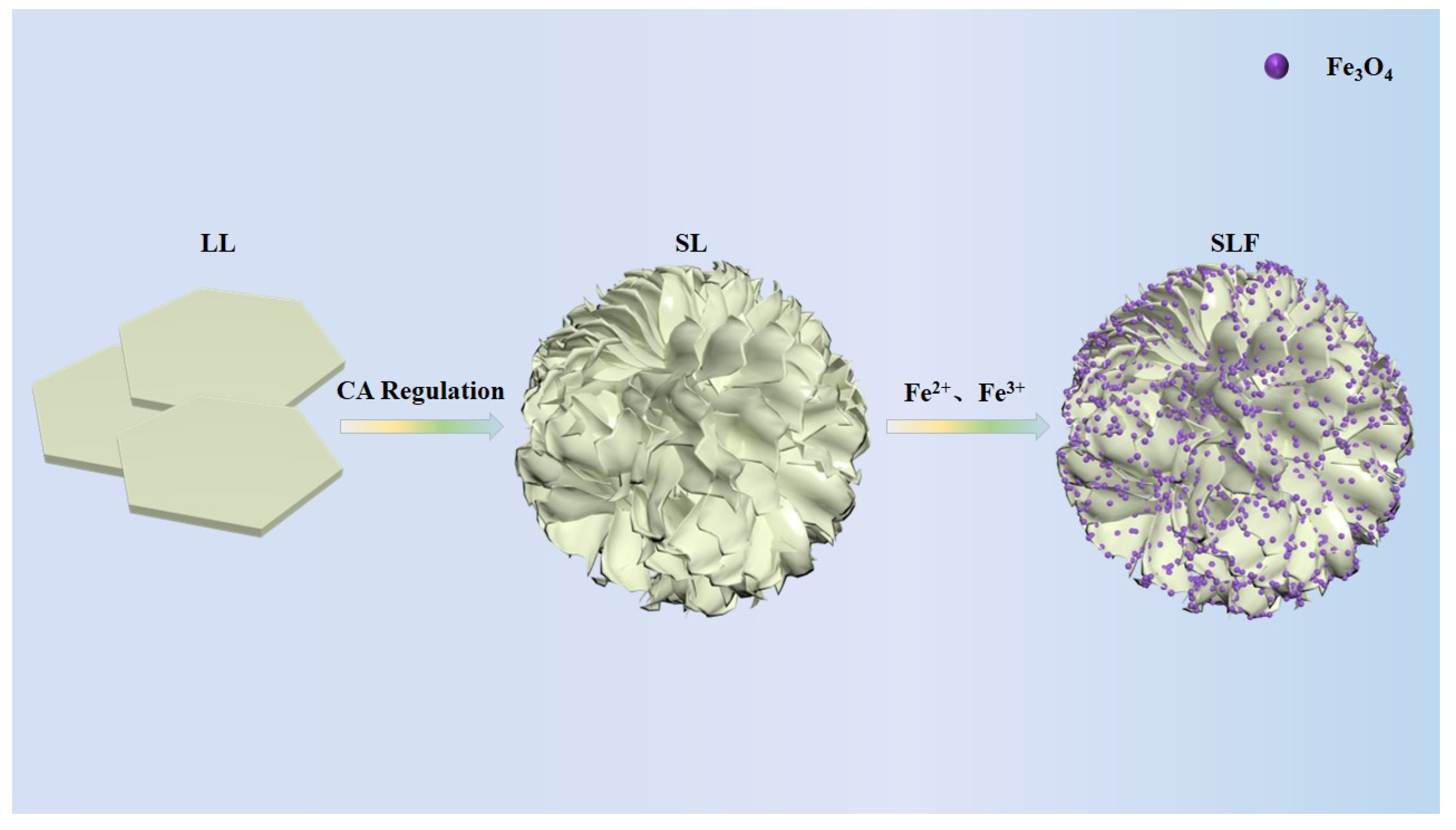
Figure 2.
XRD patterns of LL, SL, and SLF samples.
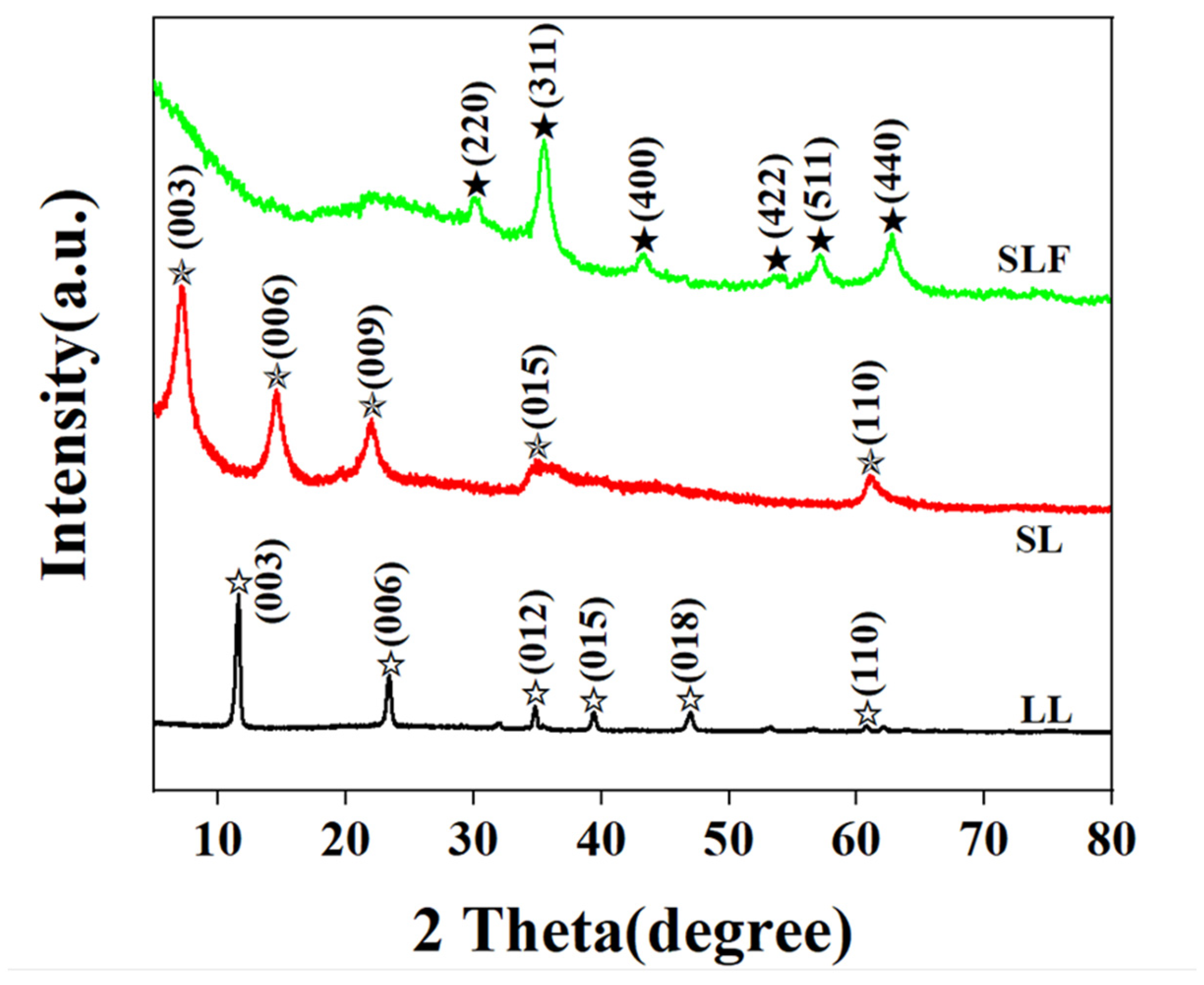
Figure 3.
FT-IR spectra of LL, SL, and SLF sample.
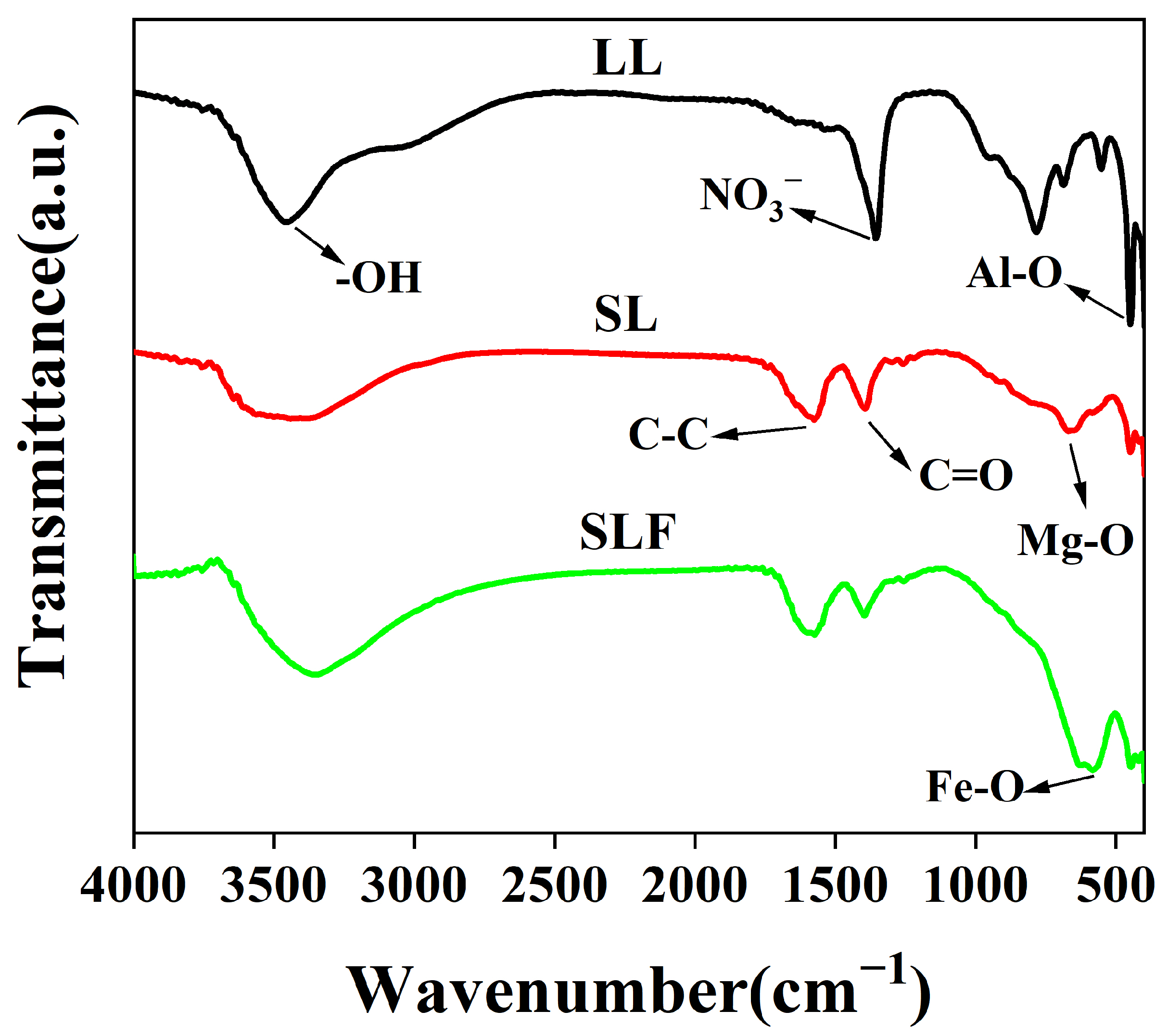
Figure 4.
(a) XPS spectra of SLF sample and (b–f) high-resolution XPS spectra of (b) Mg 1s, (c) Al 2p, (d) C 1s, (e) O 1s, and (f) Fe 2p for the SLF.
Figure 4.
(a) XPS spectra of SLF sample and (b–f) high-resolution XPS spectra of (b) Mg 1s, (c) Al 2p, (d) C 1s, (e) O 1s, and (f) Fe 2p for the SLF.

Figure 5.
(a–c) SEM images of (a) LL, (b) SL, (c) SLF; (d,e) TEM images of (d) SL and (e) SLF [20]; and (f–i) the EDX element mappings corresponding to the following (e): (f) Fe, (g) O, (h) Mg, and (i) Al.
Figure 5.
(a–c) SEM images of (a) LL, (b) SL, (c) SLF; (d,e) TEM images of (d) SL and (e) SLF [20]; and (f–i) the EDX element mappings corresponding to the following (e): (f) Fe, (g) O, (h) Mg, and (i) Al.
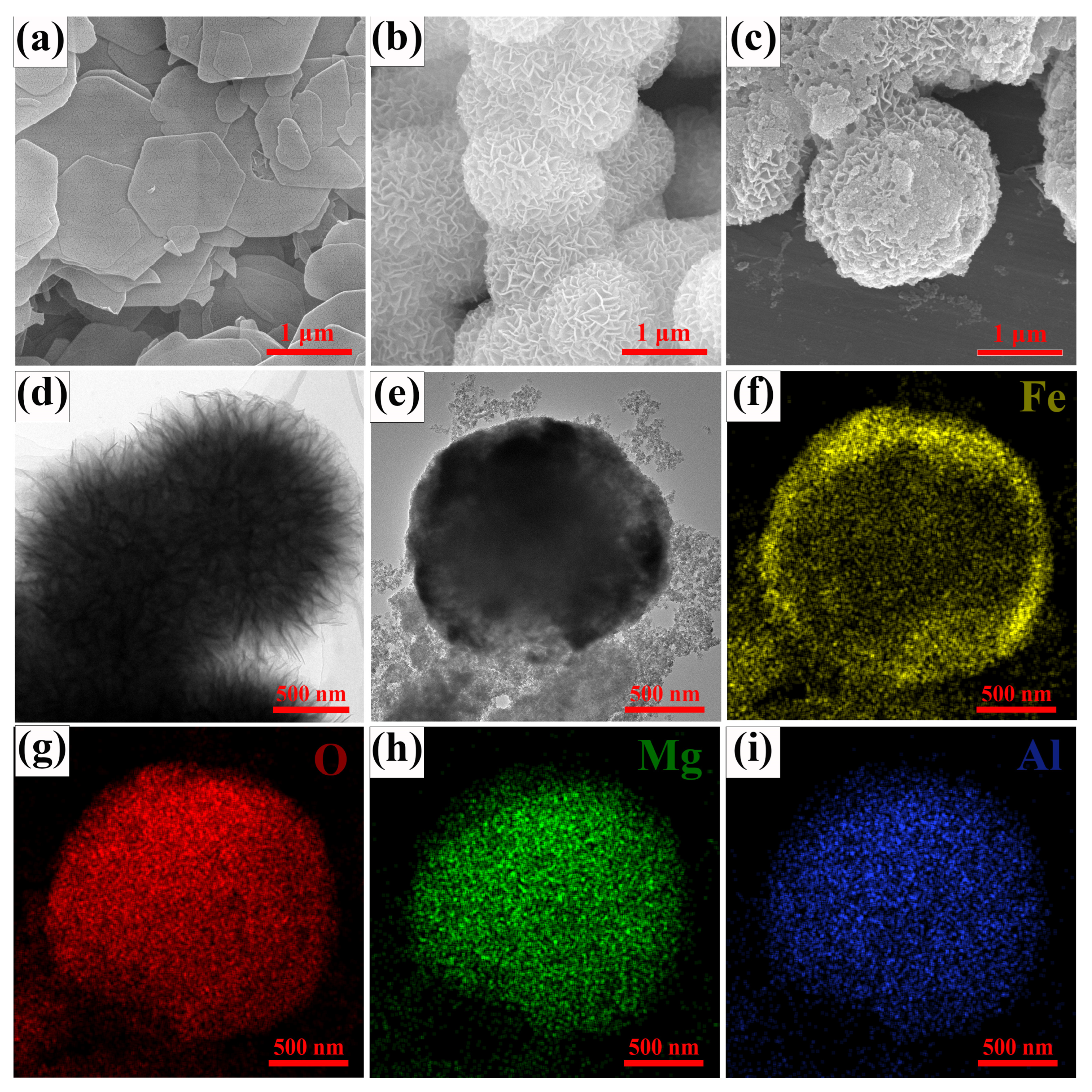
Figure 6.
The frequency dependence of (a) ε′, (b) ε″, (c) μ′, and (d) μ″ for LL, SL, and SLF samples. (e) Dielectric loss and (f) magnetic loss tangents of LL, SL, and SLF sample.
Figure 6.
The frequency dependence of (a) ε′, (b) ε″, (c) μ′, and (d) μ″ for LL, SL, and SLF samples. (e) Dielectric loss and (f) magnetic loss tangents of LL, SL, and SLF sample.

Figure 7.
(a,c,e) 3D and (b,d,f) 2D reflection loss of (a,b) LL, (c,d) SL, and (e,f) SLF sample.

Figure 8.
(a) Attenuation constant and (b) impedance-matching characteristics of LL, SL, and SLF sample.
Figure 8.
(a) Attenuation constant and (b) impedance-matching characteristics of LL, SL, and SLF sample.

Figure 9.
Schematic representation of MA mechanism of SLF/EP coating.

Figure 10.
(a,c,e,g) Bode and (b,d,f,h) Nyquist diagrams of (a,b) EP, (c,d) LL/EP, (e,f) SL/EP, (g,h) SLF/EP samples at different immersion times in 3.5 wt% NaCl solution.
Figure 10.
(a,c,e,g) Bode and (b,d,f,h) Nyquist diagrams of (a,b) EP, (c,d) LL/EP, (e,f) SL/EP, (g,h) SLF/EP samples at different immersion times in 3.5 wt% NaCl solution.
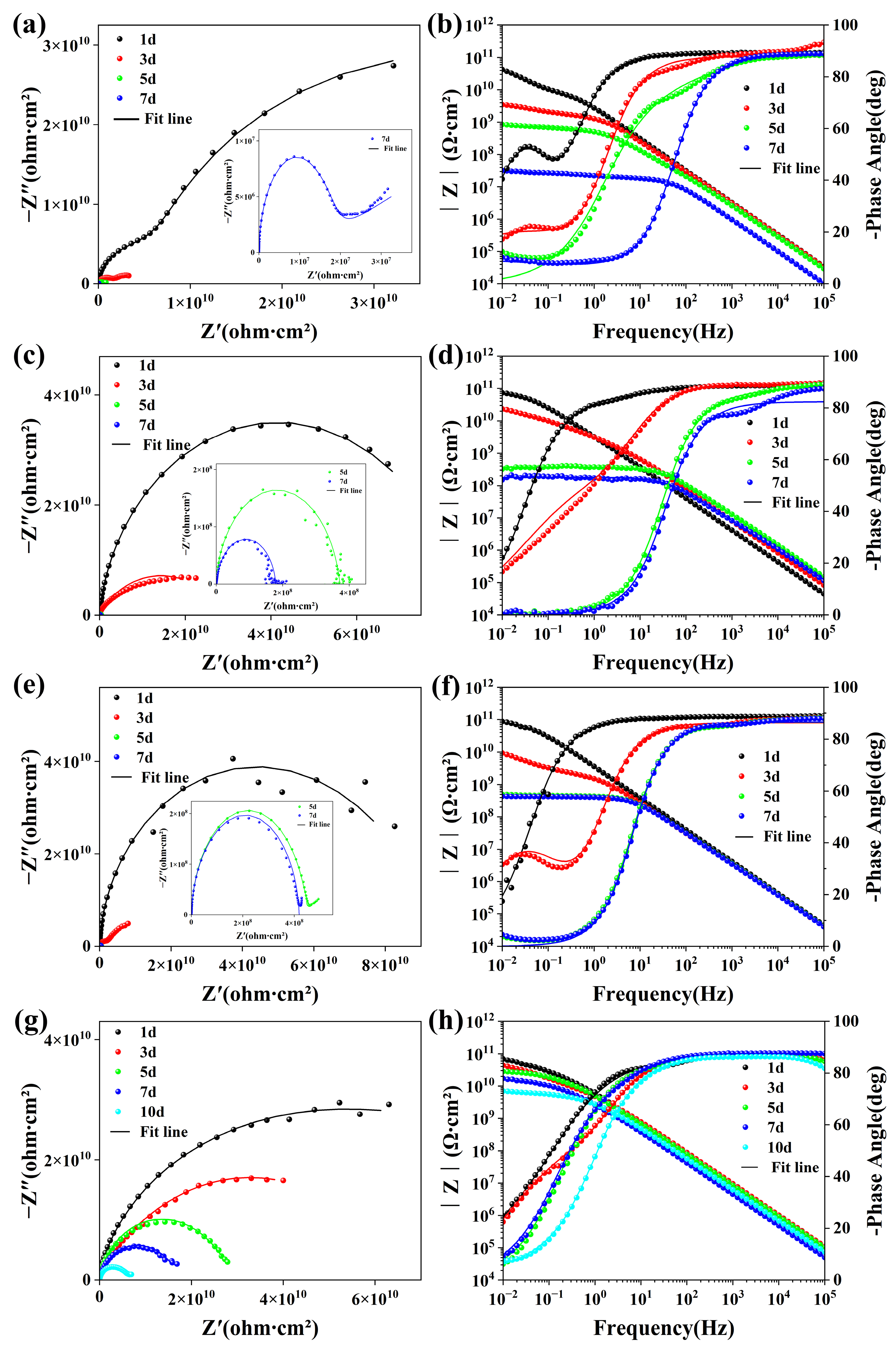
Figure 11.
Corrosion morphology of (a) EP, (b) LL/EP, (c) SL/EP, and (d) SLF/EP coatings before and after exposure to salt spray test for 240 h.
Figure 11.
Corrosion morphology of (a) EP, (b) LL/EP, (c) SL/EP, and (d) SLF/EP coatings before and after exposure to salt spray test for 240 h.

Figure 12.
Schematic representation of corrosion protection for the steel with (a) SLF/EP coating and (b) EP composite coating.
Figure 12.
Schematic representation of corrosion protection for the steel with (a) SLF/EP coating and (b) EP composite coating.

Figure 13.
(a) UV-Vis spectra of EP, LL/EP, SL/EP, and SLF/EP coatings; (b) FT-IR of EP, LL/EP, SL/EP, and SLF/EP coatings before and after 24 h UV aging.
Figure 13.
(a) UV-Vis spectra of EP, LL/EP, SL/EP, and SLF/EP coatings; (b) FT-IR of EP, LL/EP, SL/EP, and SLF/EP coatings before and after 24 h UV aging.

Figure 14.
Tribological properties of EP, LL/EP, SL/EP, and SLF/EP coatings under a load of 2 N: (a) coefficient of friction and (b) mean friction coefficient.
Figure 14.
Tribological properties of EP, LL/EP, SL/EP, and SLF/EP coatings under a load of 2 N: (a) coefficient of friction and (b) mean friction coefficient.
Disclaimer/Publisher’s Note: The statements, opinions and data contained in all publications are solely those of the individual author(s) and contributor(s) and not of MDPI and/or the editor(s). MDPI and/or the editor(s) disclaim responsibility for any injury to people or property resulting from any ideas, methods, instructions or products referred to in the content. |
© 2024 by the authors. Licensee MDPI, Basel, Switzerland. This article is an open access article distributed under the terms and conditions of the Creative Commons Attribution (CC BY) license (https://creativecommons.org/licenses/by/4.0/).
Share and Cite
MDPI and ACS Style
Yan, S.; Chen, X.; Zhang, A.; Tang, J. In Situ Synthesis of an Epoxy Resin Microwave Absorption Coating with Anti-Ultraviolet Aging Effects. Coatings 2024, 14, 514. https://doi.org/10.3390/coatings14040514
AMA Style
Yan S, Chen X, Zhang A, Tang J. In Situ Synthesis of an Epoxy Resin Microwave Absorption Coating with Anti-Ultraviolet Aging Effects. Coatings. 2024; 14(4):514. https://doi.org/10.3390/coatings14040514
Chicago/Turabian StyleYan, Shujun, Xin Chen, Angui Zhang, and Jun Tang. 2024. "In Situ Synthesis of an Epoxy Resin Microwave Absorption Coating with Anti-Ultraviolet Aging Effects" Coatings 14, no. 4: 514. https://doi.org/10.3390/coatings14040514
Note that from the first issue of 2016, this journal uses article numbers instead of page numbers. See further details here.