Article

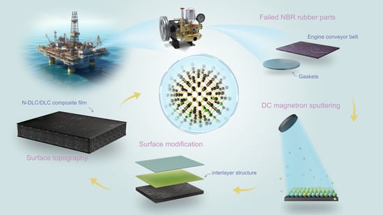
Nitrogen-Doped Diamond-like Carbon Buffer Layer Enhances the Mechanical and Tribological Properties of Diamond-like Carbon Films Deposited on Nitrile Rubber Substrate

1
Special Glass Key Laboratory of Hainan Province, School of Materials Science and Engineering, Hainan University, Haikou 570228, China
2
Key Laboratory of Advanced Technologies of Materials, College of Medicine, Ministry of Education, Southwest Jiaotong University, Chengdu 610031, China
3
School of Physics and Optoelectronic Engineering, Hainan University, Haikou 570228, China
*
Authors to whom correspondence should be addressed.
Coatings 2024, 14(4), 515; https://doi.org/10.3390/coatings14040515
Submission received: 14 March 2024 / Revised: 16 April 2024 / Accepted: 18 April 2024 / Published: 21 April 2024
(This article belongs to the Section Plasma Coatings, Surfaces & Interfaces)

Abstract

:
The poor adhesion between the DLC film and rubber restricts its application of seals. Introducing a suitable interlayer can bolster the adhesion of the coating or film. In this study, nitrogen-doped diamond-like carbon (N-DLC) emerged as the optimal intermediate layer between rubber and DLC. A series of N-DLC/DLC multilayer films were fabricated via DC magnetron sputtering on nitrile rubber (NBR) substrates, varying the substrate bias voltage (0 V, 100 V, 200 V). A scanning electron microscopy analysis revealed that the composite film surface was smoother than the DLC film alone. The results of Raman spectroscopy and X-ray photoelectron spectroscopy indicated a robust bond between nitrogen and carbon atoms in the composite film, with nitrogen facilitating the conversion of sp3C-C bonds into sp2C=C. Mechanical tests demonstrated that the N-DLC interlayer improved film adhesion and reduced the CoF of the composite film to 0.2–0.3. Specifically, the CoF of the N-DLC/DLC film prepared at 100 V was as low as 0.20, with a wear amount of 1.13 mg. Consequently, the inclusion of the N-DLC interlayer substantially enhanced the mechanical and tribological properties of DLC-coated NBR, rendering this coating highly advantageous for various applications.

Graphical Abstract

1. Introduction

Nitrile butadiene rubber (NBR) is a synthetic rubber that has excellent oil and heat resistance, making it suitable for various applications such as seals and bearings in the marine engineering and aerospace industries [1,2,3,4,5]. However, NBR is susceptible to significant friction and wear when it comes into contact with engineering materials, resulting in potential material loss and seal failure. Currently, numerous researchers have sought to address the shortcomings of NBR by enhancing formula design and processing technology. However, despite these efforts, various challenges remain in improving the tribological properties of rubber through surface modification and process optimization. Simultaneously, the adhesion between the substrate and the material of surface modification should also be considered [5,6,7]. Surface modification can significantly improve the surface wear resistance of materials without changing the matrix, and it has been studied for rubber surface modification. Diamond-like carbon (DLC) is an appealing coating material for NBR because of its characteristics such as low friction, high hardness, and chemical inertness [8,9,10]. However, there are a few obstacles to overcome in the deposition of DLC films on NBR substrates, including insufficient adhesion, excessive residual stress, and mismatched mechanical characteristics.
It is well known that enhancing the bonding strength at the interface between the film and the matrix is one of the key factors in increasing the mechanical properties of DLC films [11]. Peng et al. studied N-doped hydrogenated DLC (a-C:H:N) coatings, and the prepared coatings reduced the internal stress and surface hardness of the carbon film, but the wear resistance was not improved [12]. Wu et al. fabricated DLC/Ti-DLC films with varying Ti-DLC contents on an NBR substrate using the dual-target magnetron sputtering method. By incorporating titanium (Ti) into the interface transition layer of Ti-DLC, that composite film exhibits a comparatively low coefficient of friction (CoF), high hardness, and excellent uniformity [8]. While the sandwich design significantly improves the mechanical properties, the toughness of the film is decreased by the large metal particles, and the wear resistance in tribological applications is not increased. To enhance the adhesion of DLC films to NBR substrates, many researchers typically consider common options such as silane coupling agents, metal bonding layers, and polymeric interlayers as interlayer materials. However, the brittle fracture of the film still results in higher friction and wear under higher loads [13]. It has been demonstrated that membrane-based bonding can be enhanced using nitrogen-doped transition layers [14,15,16]. At the same time, N-DLC films face challenges in adhesion, such as mechanical property mismatches, coating uniformity, and environmental factors, which require finding solutions to optimize their adhesion properties and improve stability.
Applying bias voltage during the deposition of N-DLC and DLC films influences film growth, adhesion strength, residual stress, surface energy, and interface morphology [17,18]. Higher biasing voltages enhance film–substrate interactions, leading to denser films with stronger adhesion, while lower voltages may result in weaker adhesion [19]. By optimizing biasing voltage parameters, researchers can tailor the deposition process to improve adhesion characteristics, ultimately enhancing the performance and durability of N-DLC and DLC coatings in diverse applications.
This study investigates the structure and properties of the NBR/N-DLC/DLC composite film system, where N-DLC serves as an intermediate layer (approximately 80 nm thick) between NBR and DLC. DC magnetron sputtering was employed to deposit multilayer films on nitrile rubber substrates using varying deposition biases. Through the optimization of the substrate bias parameters, we achieved strong adhesion and outstanding tribological properties in the NBR/N-DLC/DLC coating system, offering a novel approach for the surface modification of hard coatings on NBR.

2. Materials and Methods

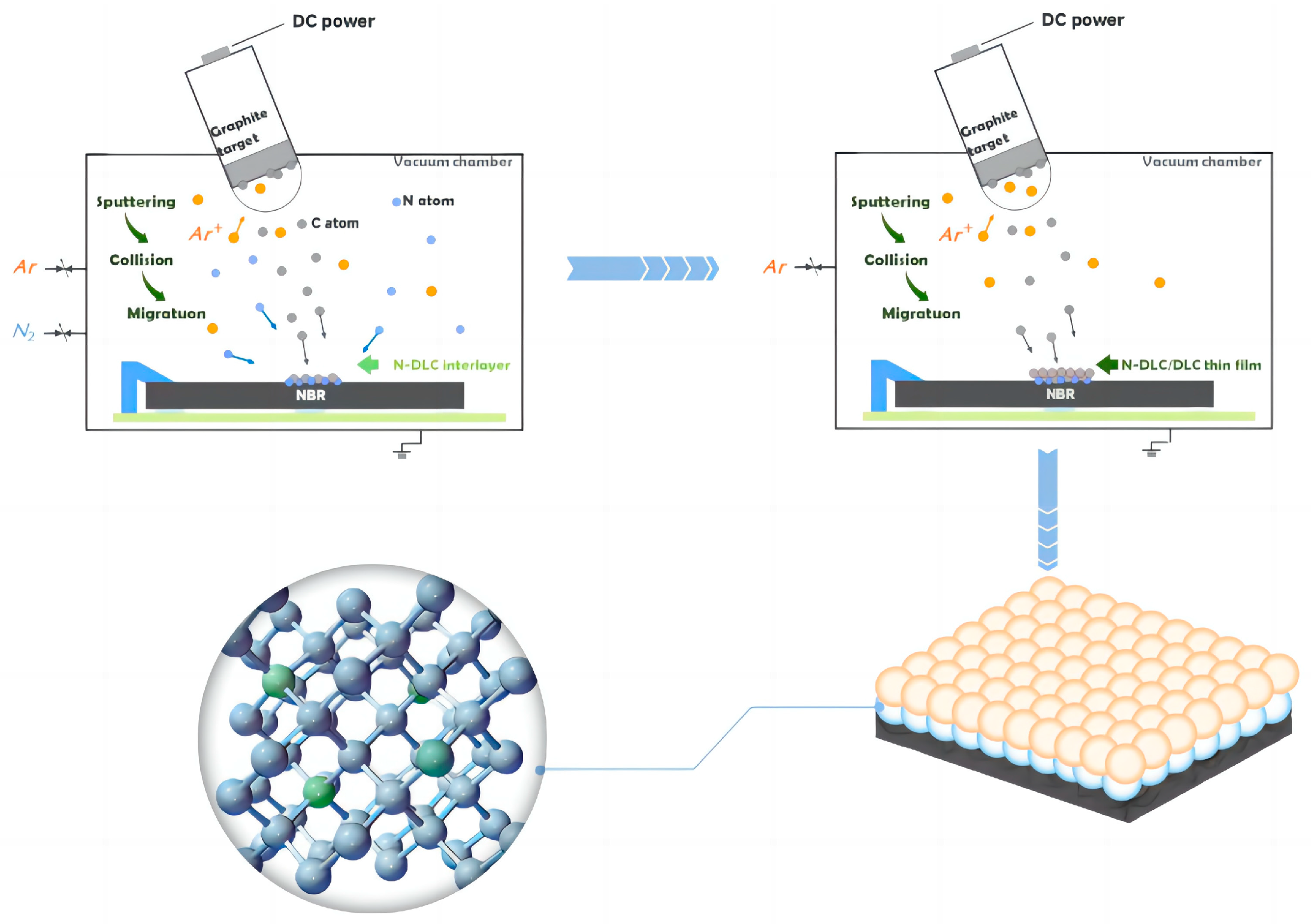
2.1. Films Preparation

Nitrile rubber (20 mm × 20 mm × 6 mm) and silicon wafer (30 mm × 10 mm × 0.5 mm) were used as substrates in this work. The substrates underwent ultrasonic cleaning in deionized water followed by ethanol for 10 min before they were placed in the vacuum chamber. Using a DC power supply magnetron discharge, a balanced magnetron sputtering system (GLH200E, KYZK Co., Ltd., ShenYang, China) with uniformity, a high-intensity magnetic field, and multi-polar properties was used to prepare the films. A DC voltage power was applied to create a negative bias between the target and the substrate during the DC magnetron sputtering process. A graphite target (Φ76.2 mm × 5 mm) was positioned at a 45° angle 80 mm above the sample stage. High-purity argon plasma was utilized to sputter the target and substrates for 10 min (−600 V bias voltage), respectively, in order to clean their surfaces before installing the DLC layer.
High-purity argon (Ar) was used as the sputtering gas (30 sccm) and high-purity nitrogen (N2) as the reaction gas for depositing the intermediate layer, with a deposition pressure of 1.4 Pa. The N-doped DLC intermediate layer (M1, M2, and M3) was prepared via sputtering for 30 min at bias voltages of 0 V, −100 V, and −200 V. The film preparation parameters are shown in Table 1.
The diamond-like films deposited without the transition layer under the same bias voltage conditions (bias voltages of 0 V, −100 V, and −200 V) were labeled as P1, P2, and P3. They will appear in some of the following characterizations for comparison. The main parameters of the film are shown in Table 2.
Diamond-like carbon films were deposited outside the transition (interlayer) layer for 30 min at a bias voltage of −100 V. The prepared composite coatings were labeled as C1, C2, and C3, respectively. The main coating parameters of the multilayer films are detailed in Table 3, while the deposition process is shown in Figure 1.

2.2. Characterization

A field emission scanning electron microscope (GeminiSEM 360, Carl Zeiss AG, Jena, Germany) was used to characterize the surface morphology of the N-DLC interlayer and the surface morphology of the multilayer films. The chemical bonding structures of the N-DLC interlayer and the multilayer films were determined via X-ray photoelectron spectroscopy (XPS; Thermo Fisher Scientific, Waltham, MA, USA, Escalab 250Xi) with monochromatic aluminum (Al) Kα radiation at an energy level of 1486.6 eV. Prior to obtaining XPS spectra, no ion sputtering was employed. To calibrate the energy of the measured XPS spectral data, the peak center position of the carbon 1s peak was set to 284.4 eV as a reference energy. The structure of the multilayer films and DLC was determined using a Raman spectrometer (Nano Finder 30A, Tokyo Instruments, INC, Japan) with a 514 nm laser and acquired within the range of 50 cm−1 to 4000 cm−1. In order to further analyze the uniformity of the N-DLC interlayer and the N-DLC/DLC composite film, the Raman mapping was further observed on an area of 100 μm × 100 μm using silicon substrate because rubber substrate may contain various organic compounds notwithstanding the silicon substrate having minimal Raman activity compared to rubber. Using silicon as the substrate can reduce background interference in Raman spectra, allowing for a clearer identification and analysis of the carbon film’s Raman signature. The laser power was carefully regulated at 1 mW to optimize the signal intensity of the DLC film [8].
The adhesion strength of the N-DLC/DLC multilayer films was assessed utilizing a micro-scratch tester (CETR-UMT, Bruker, Billerica, MA, USA) equipped with a 25 μm diameter diamond stylus, and the load applied to the coatings was progressively increased from 0.1 N to 3 N with a scratch length of 2 mm. It should be pointed out that there is no comparison between the film bonding forces measured under different test conditions because the critical load measured through scratch experiments depends on many factors, such as indenter geometry, sliding rate, force loading rate, and contact mode. Evidently, these factors are different for different test conditions. The evaluation of the bonding strength of the film needs to be carried out under the same testing conditions to obtain more accurate results. The mechanical properties of N-DLC/DLC films were analyzed using a nanoindenter (CETR-UMT, Bruker). The load was incrementally raised to a peak value of 1 mN over 10 s, then maintained for another 10 s. Subsequently, the load was reduced to 0.1 mN and held constant for 45 s to compensate for thermal drift. Five random tests were performed on every sample, and the distance between adjacent indentations was greater than 10 mm. The hardness and modulus of elasticity of the N-DCL/DLC multilayer films were determined with the Oliver–Pharr method [20]. The wear performance of the N-DLC/DLC multilayer films at room temperature (25 °C, 45% RH) was evaluated using a ball-on-disk tribometer (CETR-UMT, Bruker). The ZrO2 ball (diameter of 1.6 mm) was chosen as the tribo-pair with the films, the wear load was 0.3 N, and it was slid on a circular path with a radius of 4 mm at a speed of 100 revolutions per minute for 30 min. Then, the wear tracks and chemical bonding of the NBR/N-DLC/DLC composite coating were examined using a laser confocal microscope (VK-using X200 series, KEYENCE) and a Raman spectrometer (Japan-Horiba Scientific-LabRAM HR Evolution). After each friction test (three), the change in mass of the sample was measured with a balance (LabX Ready, XSE105) to obtain data on the amount of wear.

3. Results and Discussion

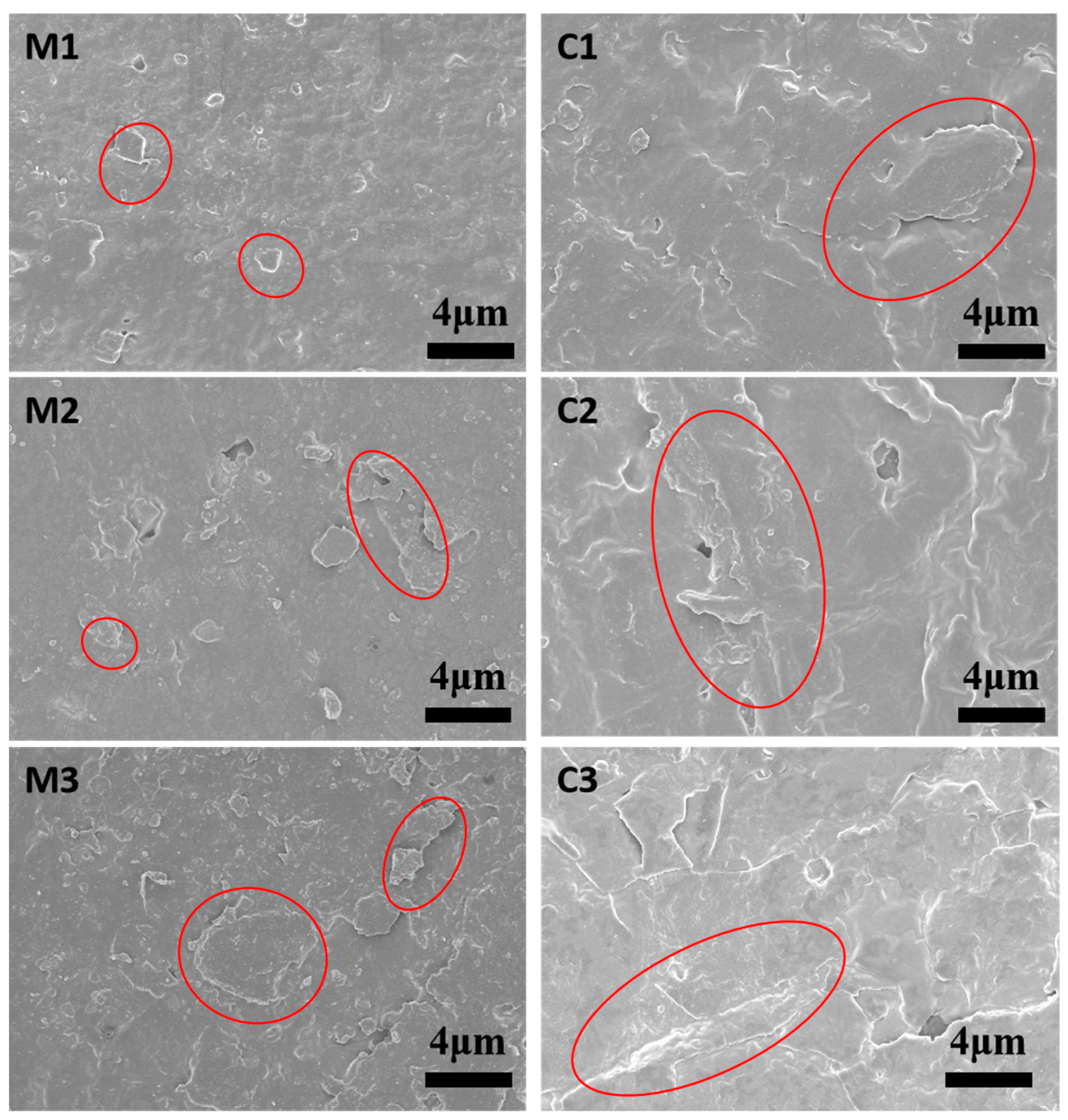
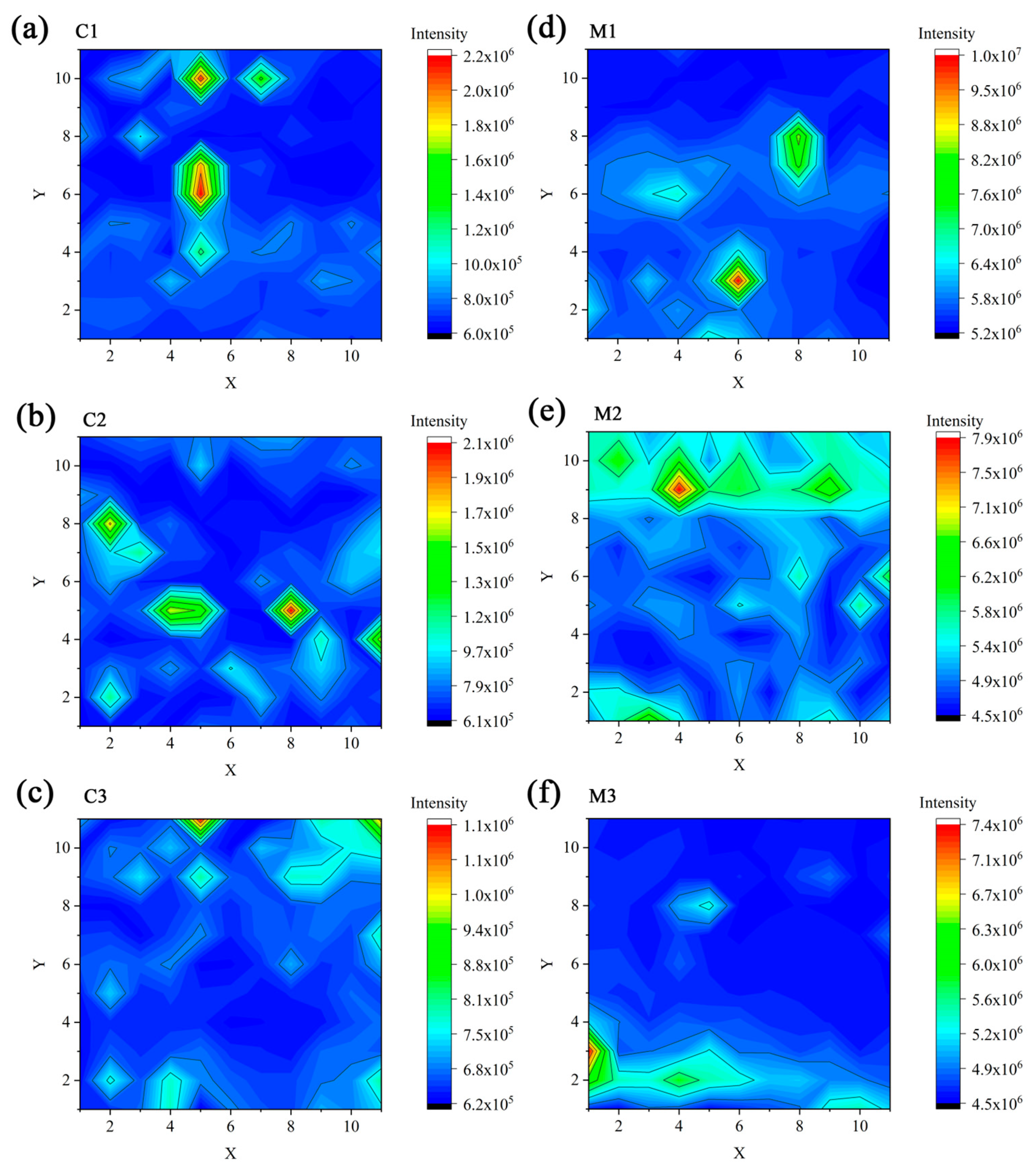
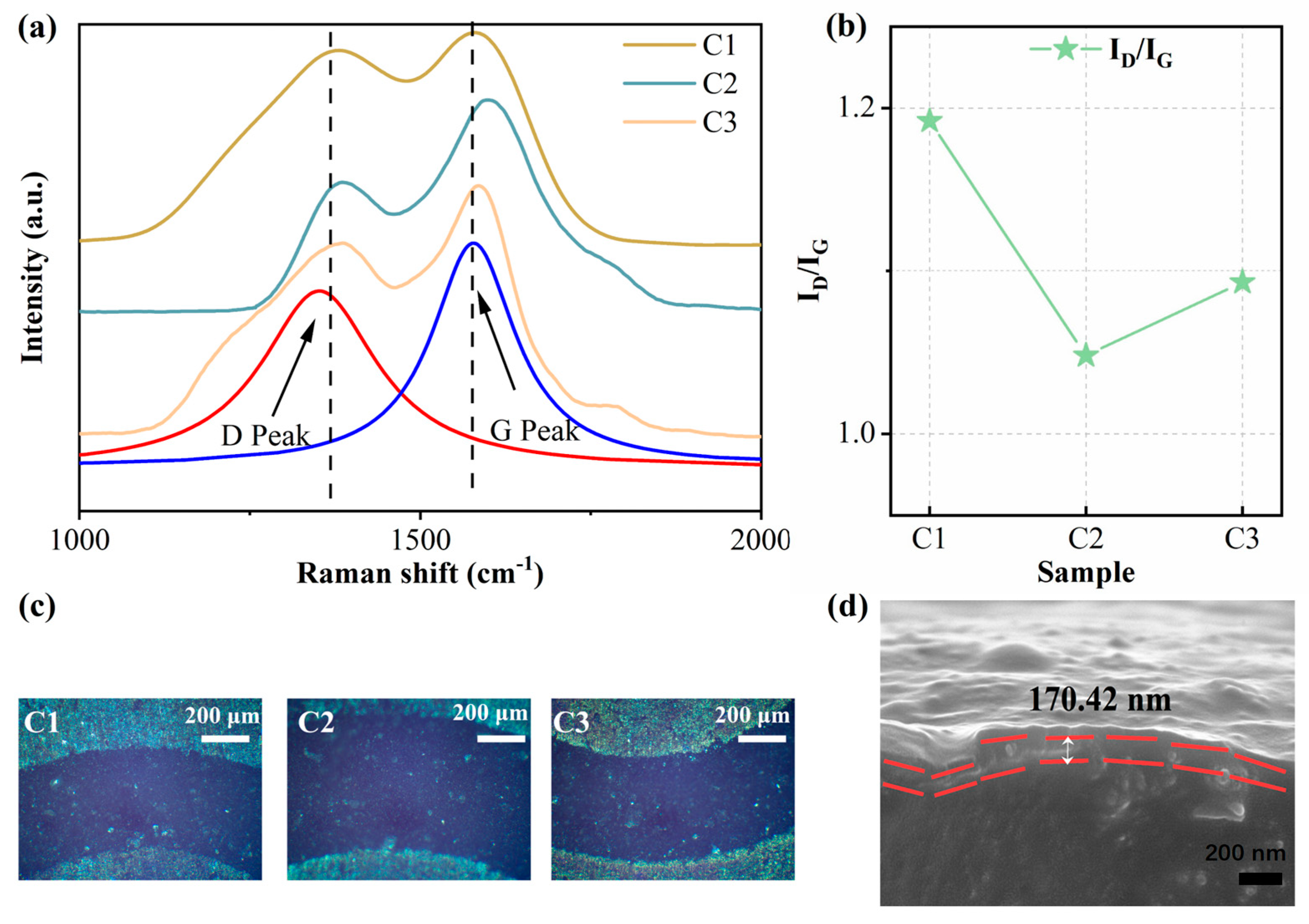
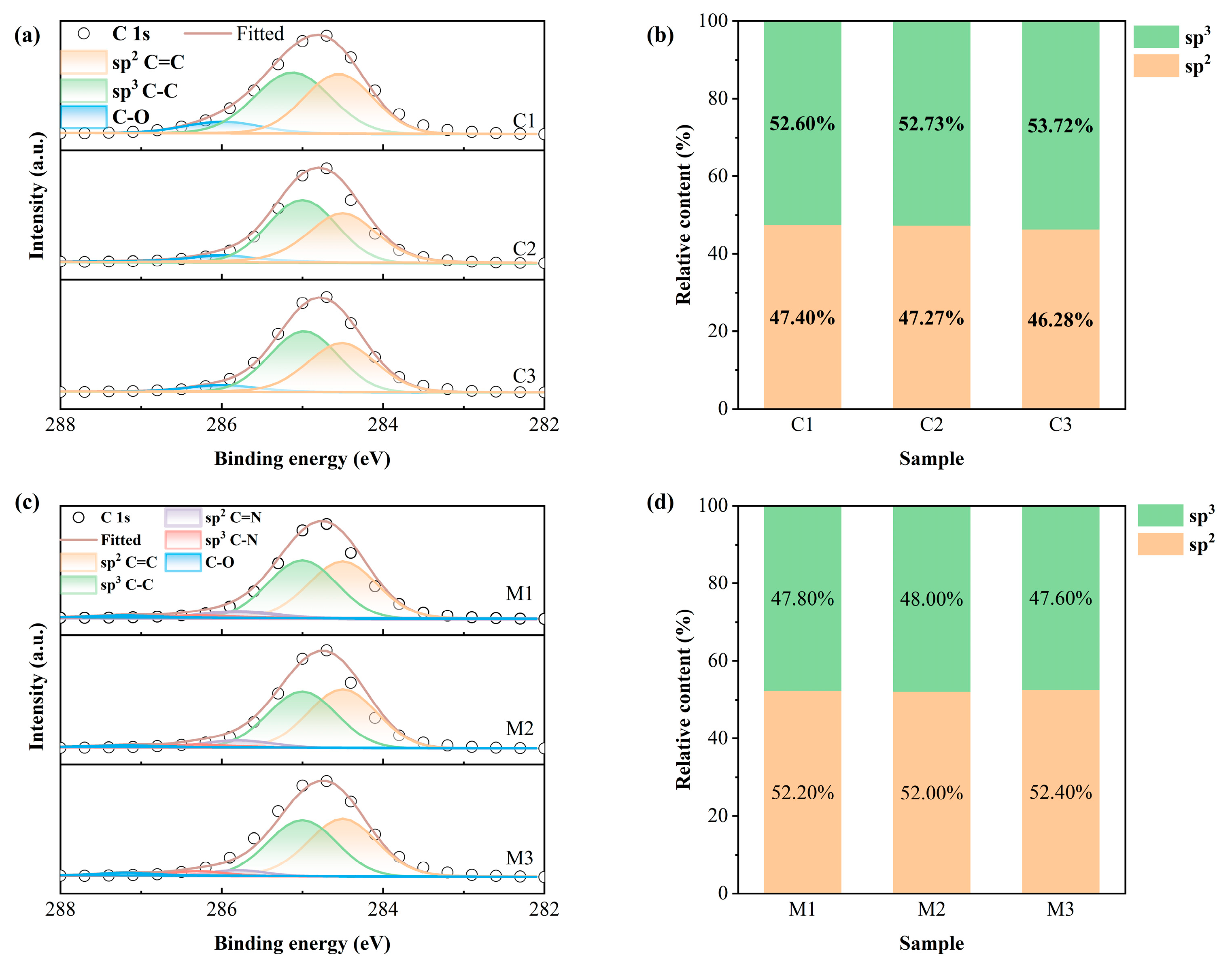
3.1. Morphology and Structure

The red circles in Figure 2 shows the irregular cracks and broken patches of the as-prepared DLC films coated on NBR. This is brought on by the variation in temperature during the film deposition process, which is further influenced by the difference in the DLC film’s and the rubber base’s coefficients of thermal expansion. At the same time, these cracks release some of the internal stresses in the DLC films and improve the toughness of DLC films on NBR [21]. The presence of the N element affects the nucleation and mutual collision of carbon atoms during the deposition of DLC films [22]. The morphology of the N-DLC interlayer in this study is shown in Figure 2 (M1, M2, and M3), which shows that the surface of the N-DLC interlayer is smoother than that of the DLC films (C1, C2, and C3).
Figure 3 shows the Raman spectra and corresponding ID/IG ratios of deposited DLC films with and without N-DLC interlayers at different bias voltages. As shown in Figure 3a, the spectra were fitted via the Gaussian function, which possesses two peaks in each spectrum. The D peak is formed due to a specific vibrational pattern of the sp2C=C carbon atom in the carbon film, whereas the G peak is formed by the expansion of sp2C=C to sp3C-C [23,24]. The Raman results indicate that the ID/IG of the N-DLC/DLC composite film does not change significantly due to the same deposition bias voltage of the outer layer. Simultaneously, the major peak of the DLC film’s symmetry center stays comparatively steady as the negative bias voltage rises. Jang et al. used N to replace some of the carbon atoms in the tetrahedral amorphous carbon in the film, indicating that the degree of graphitization of the film is related to the number of carbon atoms in the N-substituted amorphous carbon [25,26]. According to this study, the structure of the pure DLC film covering the outer surface of the multilayer film is mostly unaffected by the N-DLC interlayer, although it does have an impact on the chemical bonding state of the carbon atoms in the DLC film. The results are shown in Figure 3b,c. Generally speaking, when nitrogen enters the carbon grid, nitrogen atoms preferentially combine with carbon atoms to form p bonds, forming many new sp2 sites [27]. In this case, these new sp2 sites combine with each other and promote the graphitization process of the DLC film [28]. For more information, refer to Figure S1 in the Supplementary Materials, which shows the surface roughness of the final DLC film with that of both the substrate and N-DLC buffer layer. In order to further investigate the properties of N-doped multilayer films, the Raman mapping of the N-DLC interlayer was performed.
The N-DLC interlayer and the multilayer film containing the interlayer were further investigated via Raman mapping at different bias voltages. As shown in Figure 4, the DLC films exhibit a uniform color distribution over a 100 μm × 100 μm area, indicating the existence of a homogeneous chemical structure at the microscopic level [8,29]. Raman mapping shows that N-DLC interlayers with 0 V, −100 V, and −200 V interlayer bias voltages maintain homogeneity. Meanwhile, the homogeneity of the N-DLC/DLC multilayer films was also maintained under different conditions. This suggests that the bias voltage’s influence is insensitive to the film’s surface uniformity. Notably, even at lower energies, the energetic particles’ contact with the NBR substrate results in an increased level of NBR ionization. Consequently, the film experiences an inherent densification process that enhances its consistency.
Figure 5 shows the fitted XPS C1s spectra of thin carbon films (composite film and interlayer) deposited on NBR at different interlayer bias voltages. As shown in Figure 5a, there are three typical peaks in the C1s spectra of the multilayer films, which represent the sp2C=C, sp3C-C, and C-O bonds, respectively [30,31]. Of all the peaks in the multilayer films, the C-C bond peak at 285.1 eV has the most area, which indicates a higher sp3 content in the surface DLC film. DLC films frequently contain C-O bonds because of the film’s surface oxidation in the environment. As shown in Figure 5c, when the DLC film is doped with nitrogen, the original spectrum of C1s is decomposed into five peaks, located at 284.4 ± 0.1 eV, 285.1 ± 0.1 eV, 285.9 ± 0.1 eV, 286.5 ± 0.2 eV, and 287.3 ± 0.1 eV. These represent sp2C=C, sp3C-C, C=N, C-N, and C-O bonds, respectively [12]. Among the observed peaks, the C=C bond peak at 284.4 eV has the most area. This is contrary to the result of Figure 5a, indicating that the addition of nitrogen has a favorable effect on the conversion of sp3C-C bonds to sp2C=C. This discovery aligns with the conclusions reached from the Raman spectroscopy analysis. This is confirmed by the variation of the sp2C=C/sp3C-C ratio, the results of which are shown in Figure 5b,d.
It is worth mentioning that, when nitrogen is doped into the DLC film, two peaks appear: C=N (285.9 ± 0.1 eV) and C-N (286.5 ± 0.2 eV); sp3C-N indicates that sp3-hybridized carbon atoms are bonded to nitrogen atoms to form σ bonds; and sp2C=N means that the sp2-hybridized carbon atom is bonded to the nitrogen atom to form a σ+π double bond [12,32,33]. The results show that the nitrogen and carbon atoms in the multilayer films are well bonded. The corresponding content percentages of sp2C=C and sp3C-C obtained from the fitting results are shown in Figure 5b,d, which are consistent with the Raman-derived 0.92, 0.89, and 0.91 (ID/IG) for the N-DLC/DLC composite coatings. N1s spectra of the interlayer were also decomposed into sp2N=C and sp3N-C bonds. The change tendency of sp2N-C/sp3N-C is the same as that shown in Figure 5d. The detailed information can be seen in the Supplementary Materials and Figures S2 and S3. In particular, the N-DLC interlayer sp2/sp3 results of 1.09, 1.03, and 1.10 (M1, M2, and M3, come from Figure 5d) are significantly different from the multilayer films with sp2/sp3 values of less than one. This is because N doping encourages the film’s graphitization process [25].

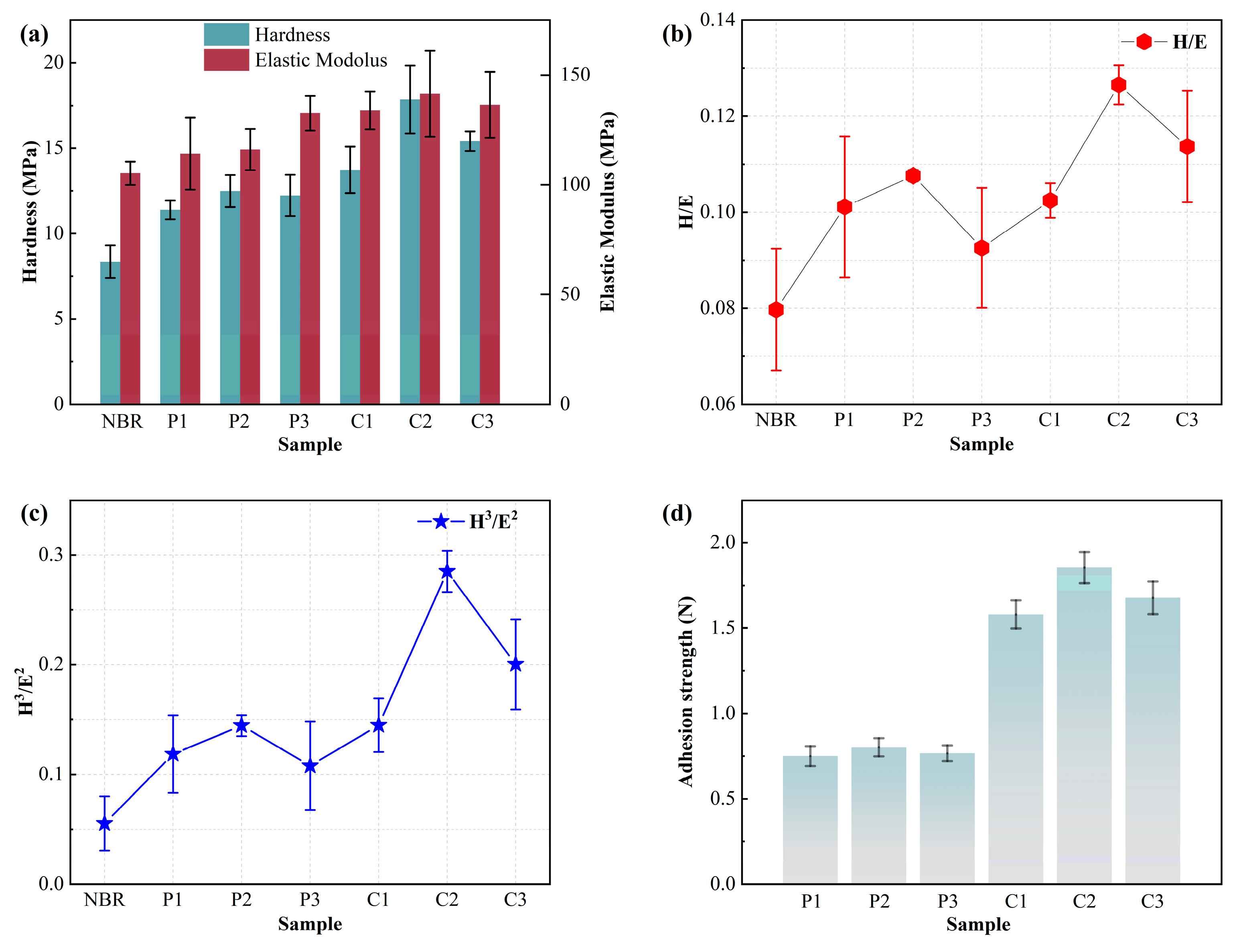
3.2. Mechanical Properties

The hardness and Young’s modulus results of the DLC and multilayer films were calculated using the Oliver–Pharr method and are shown in Figure 6a. Owing to the natural elasticity and viscous flow of NBR, high loading and duration may cause the recorded Young’s modulus value to rise [34]. Therefore, the nanoindenter was maintained at the maximum indentation load (1 mN) for 10 s while compensating for temperature drift in order to reduce the inaccuracy [8,35]. It should be noted that the indentation rebound depth exceeds 600 nm throughout the loading process, which is greater than the thickness of the composite film, which is about 170 nm. It should be noted that by appropriately regulating the discharge settings, the deposition rate is guaranteed to be extremely reproducible from run to run, minimizing the disparities in the groupings’ film thicknesses. Therefore, the total hardness of the NBR, N-DLC interlayer, and DLC should be the measured hardness value [36]. The general characteristics of materials are more realistic in real-world applications. As a result, the rubber and film’s composite hardness and modulus are more practically significant.
The Young’s modulus (E) and hardness (H) of the films with and without a N-DLC interlayer are significantly different, and the results are shown in Figure 6a. It is easy to see that the hardness of the DLC films with the N-DLC interlayer is slightly higher than that of the DLC without the interlayer, with the C2 sample having the highest hardness of 17.8 MPa. It has been shown that the hardness and Young’s modulus of hydrogen-free DLC films are influenced by the carbon bond configuration [37,38,39]. In this study, the N-DLC interlayer affects the hardness and Young’s modulus. That is, the addition of the interlayer enhances the mechanical properties of multilayer structures, including stiffness and behavior [40]. The H/E values of pure DLC film on NBR varied from 0.092 to 0.107, and the H/E values of DLC film with the N-DLC interlayer on NBR varied from 0.102 to 0.126; the results are shown in Figure 6b. Higher H/E values resist the impact of the matrix and do not fracture when a load is applied, which is associated with an increase in the mechanical work dissipated during plastic deformation [41,42,43]. In this study, DLC films with the N-DLC interlayers have higher H/E values. The H3/E2 values can effectively characterize a material’s resistance to plastic deformation [44,45]. The H3/E2 value of sample C2 is 0.285, markedly exceeding that of the pure DLC films (0.107–0.144), and the result is shown in Figure 6c. According to reports, H/E and H3/E2 are significant markers for assessing a membrane’s capacity to withstand plastic and elastic deformation, respectively [46]. As a result, it was determined that the C2 sample in the current investigation had superior wear resistance due to its optimal hardness, H/E, and H3/E2.
The bond strength of multilayer films was assessed using scratch testing to determine the critical breaking load between the film and the substrate, and the results are shown in Figure 6d. The research results show that the composite film with a N-DLC interlayer exhibits a higher critical load than the pure DLC film. When a carbon atom forms four equivalent sp3 hybrid orbitals through sp3 hybridization, it forms a σ bond with the lone pair of electrons of the nitrogen atom, which is formed by the overlap of the two orbitals [12,32,33]. As a result, adding nitrogen strengthens the interface’s bonding strength and increases the stability of the chemical connections there.

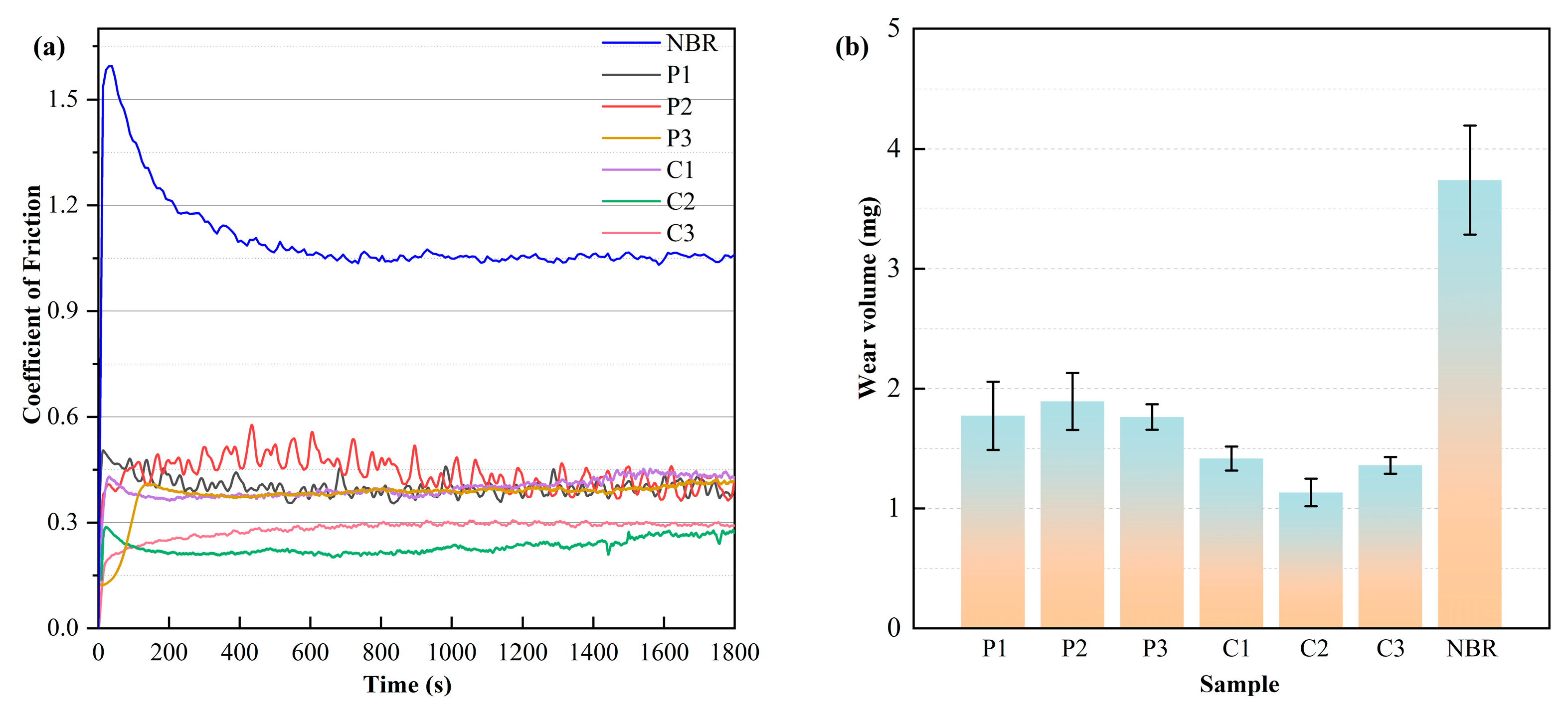
3.3. Tribological Properties

Figure 7a presents the coefficient of friction (CoF) of the films and NBR substrate. The CoF of NBR is about 1.0. Other films exhibit different properties due to the influence of the negative bias voltage of the interlayer with different adhesion strengths. Obviously, the CoF of the multilayer films containing the interlayer is lower than that of the pure DLC films. During the 1800 s test, the CoF of the pure DLC films remained basically unchanged at around 0.5. In particular, sample C2 has the lowest CoF value, from about 0.2 to 0.3, and remains stable during the testing process, with excellent tribological properties. The difference in CoF between the films is related to the addition of the N-DLC interlayer, which is doped with nitrogen atoms to disrupt the carbon bonding structure [47]. The curve in Figure 7a shows that the composite film with the N-DLC interlayer has a lower CoF. This aligns with the outcomes of the multilayer films’ XPS C1s spectrum investigation.
In order to investigate the abrasion resistance of DLC films on rubber substrates, film wear measurements were carried out, and the results are shown in Figure 7b. Under dry friction conditions, the highest wear rate was observed for NBR. Both the quantity of wear and the coefficient of friction were considerably lower following the DLC surface deposition. Among them, C2 with the N-DLC interlayer has the least amount of wear. This is due to the fact that it has the largest H3/E2 and, therefore, better wear resistance [45]. In order to better study the friction mechanism, the wear traces were analyzed via Raman analysis.
Raman spectra were also used to analyze the wear tracks of multilayer films, as seen in Figure 8a. As shown in Figure 8b, the ID/IG increases significantly at the wear traces relative to the composite film surface. Reducing the direct contact between friction surfaces is facilitated via the formation of a graphite-like structure at the wear mark, as indicated by the increase in ID/IG. The composite film’s wear scar experienced graphitization as a result of frictional heat buildup, which encourages the transformation of sp3C-C bonds into sp2C=C bonds. In friction applications, graphitization enhances the coating’s performance during friction, leading to improved wear resistance and stability.
There is a clear compaction layer on the wear track of the N-DLC/DLC multilayer films, and the results are shown in Figure 8c. The formation of the compaction layer is due to the mechanical action of the sp2-rich surface under high Hertzian stresses [30,48,49,50]. The formation of this compacted layer not only increases the stability of the surface but also provides support and protection to the composite film during friction. This supporting effect helps to minimize direct contact and reduce friction, thus enabling the composite film to maintain a low coefficient of friction.

4. Conclusions

The bias voltage of the substrate was varied to deposit N-DLC/DLC films with different bias voltages: 0 V, 100 V, and 200 V. The multilayer structure enhances the adhesion force between the film and the substrate, consequently improving the mechanical and tribological properties of DLC films. Compared to the DLC film prepared at −100 V, the multilayer N-DLC/DLC film exhibits superior properties, including enhanced adhesion strength, lower CoF, and reduced wear volume. The optimal performance was observed with N-DLC/DLC biased at 100 V, demonstrating a CoF of 0.20 and a wear volume of 1.13 mg. The tribological properties of DLC films are influenced by various factors, such as surface roughness, hardness, elastic modulus, H/E ratio, and adhesion strength. In addition to producing unexpected outcomes, the study approach validated its influence and promise in real-world applications.

Supplementary Materials

The following supporting information can be downloaded at https://www.mdpi.com/article/10.3390/coatings14040515/s1: Figure S1: AFM image of the final DLC film with that of both the substrate and N-DLC buffer layer. Figure S2: (a) XPS N1s spectra of interlayer film deposited on NBR at different bias voltages; (b) corresponding sp2 and sp3 percentages of sp2N-C/sp3N-C. Figure S3: N/C percentage of interlayer films deposited on NBR under different bias voltages.

Author Contributions

Data curation, Investigation, and Methodology, Y.S., C.H., and F.W.; Funding Acquisition and Supervision, F.W.; Project Administration, Q.D. and F.W.; Writing—Original Draft, Y.S., N.Z., and Y.W.; Writing—Review and Editing, Y.L., Z.W., Q.D., and F.W. All authors have read and agreed to the published version of the manuscript.

Funding

This project is supported by the Hainan Provincial Natural Science Foundation of China (420RC525) and the Hainan Province Science and Technology Special Fund (ZDYF2019206).

Institutional Review Board Statement

Not applicable.

Informed Consent Statement

Not applicable.

Data Availability Statement

The data presented in this study are available upon request from the corresponding author.

Conflicts of Interest

The authors declare no conflicts of interest.

References

  1. Dong, C.L.; Yuan, C.Q.; Bai, X.Q.; Yan, X.P.; Peng, Z. Tribological properties of aged nitrile butadiene rubber under dry sliding conditions. Wear 2015, 322, 226–237. [Google Scholar] [CrossRef]
  2. Ahmed, F.S.; Shafy, M.; Abd El-megeed, A.A.; Hegazi, E.M. The effect of γ-irradiation on acrylonitrile–butadiene rubber NBR seal materials with different antioxidants. Mater. Des. (1980–2015) 2012, 36, 823–828. [Google Scholar] [CrossRef]
  3. Delfin, F.A.; Brühl, S.P.; Dommarco, R.C.; Forsich, C.; Heim, D. Impact of relative humidity and deposition parameters on the tribological behavior of soft DLC coatings. Surf. Coat. Technol. 2023, 474, 130100. [Google Scholar] [CrossRef]
  4. Wu, Y.; Li, K.; Shi, B.; Qi, J.; Zhou, X.; Wang, Y.; Zheng, K.; Liu, Y.; Yu, S. The effect of sputtering power on the structural and tribological behaviors at elevated temperature of Ta/Si co-doped DLC films. Surf. Coat. Technol. 2024, 482, 130688. [Google Scholar] [CrossRef]
  5. Liu, J.Q.; Li, L.J.; Wei, B.; Wen, F.; Cao, H.T.; Pei, Y.T. Effect of sputtering pressure on the surface topography, structure, wettability and tribological performance of DLC films coated on rubber by magnetron sputtering. Surf. Coat. Technol. 2019, 365, 33–40. [Google Scholar] [CrossRef]
  6. Wu, Y.; Liu, J.; Han, C.; Cao, H.; Jiang, H.; Deng, Q.; Wen, F.; Pei, Y. Improvement of the mechanical and tribological behaviors by Ti-C interlayer for diamond-like carbon films on nitrile butadiene rubber. Mater. Sci. Eng. B 2023, 290, 116289. [Google Scholar] [CrossRef]
  7. Liu, J.; Yang, T.; Cao, H.; Deng, Q.; Pan, C.; Wen, F. Diamond-like carbon films for tribological modification of rubber. Nanotechnol. Rev. 2022, 11, 2839–2856. [Google Scholar] [CrossRef]
  8. Pei, Y.T.; Bui, X.L.; Van der Pal, J.P.; Martinez-Martinez, D.; De Hosson, J.T.M. Flexible diamond-like carbon film coated on rubber. Prog. Org. Coat. 2013, 76, 1773–1778. [Google Scholar] [CrossRef]
  9. Pei, Y.T.; Bui, X.L.; De Hosson, J.T.M. Flexible protective diamond-like carbon film on rubber. Scr. Mater. 2010, 63, 649–652. [Google Scholar] [CrossRef]
  10. Liu, J.; Wu, Z.Y.; Cao, H.T.; Wen, F.; Pei, Y.T. Effect of bias voltage on the tribological and sealing properties of rubber seals modified by DLC films. Surf. Coat. Technol. 2019, 360, 391–399. [Google Scholar] [CrossRef]
  11. Lubwama, M.; Corcoran, B.; McDonnell, K.A.; Dowling, D.; Kirabira, J.B.; Sebbit, A.; Sayers, K. Flexibility and frictional behavior of DLC and Si-DLC films deposited on nitrile rubber. Surf. Coat. Technol. 2014, 239, 84–94. [Google Scholar] [CrossRef]
  12. Peng, J.; Huang, J.; Peng, Y.; Xiao, Y.; Yang, M. Investigating the effect of bias voltage on the microstructural thermal stability and tribological performance of N-doped hydrogenated diamond-like carbon coatings. Surf. Coat. Technol. 2022, 451, 129064. [Google Scholar] [CrossRef]
  13. Bhattacherjee, S.; Niakan, H.; Yang, Q.; Hu, Y.; Dynes, J. Enhancement of adhesion and corrosion resistance of diamond-like carbon thin films on Ti–6Al–4V alloy by nitrogen doping and incorporation of nanodiamond particles. Surf. Coat. Technol. 2015, 284, 153–158. [Google Scholar] [CrossRef]
  14. Vahidi, A.; Serra, R.; Ferreira, F.; Cavaleiro, A.; Oliveira, J. Assessment of thermomechanical stability of DLC films deposited by Ne-HiPIMS technology for high-temperature applications. Wear 2023, 532, 205126. [Google Scholar] [CrossRef]
  15. Capote, G.; Ramírez, M.A.; Da Silva PC, S.; Lugo, D.C.; Trava-Airoldi, V.J. Improvement of the properties and the adherence of DLC coatings deposited using a modified pulsed-DC PECVD technique and an additional cathode. Surf. Coat. Technol. 2016, 308, 70–79. [Google Scholar] [CrossRef]
  16. Yan, X.; Xu, T.; Chen, G.; Yang, S.; Liu, H. Study of structure, tribological properties and growth mechanism of DLC and nitrogen-doped DLC films deposited by electrochemical technique. Appl. Surf. Sci. 2004, 236, 328–335. [Google Scholar] [CrossRef]
  17. Zeng, H.; Liu, J.; Yang, T.; Deng, Q.; Wen, F. Effect of local pressure difference caused by argon flow on properties of DLC films on rubber. J. Vac. Sci. Technol. A 2023, 41, 053410. [Google Scholar] [CrossRef]
  18. Chen, Y.; Su, F.; Li, H.; Li, Q.; Sun, J.; Lin, S. Hydrogen-free DLC films fabricated using superimposed HiPIMS-DCMS deposition system: Bias voltage effects. Surf. Coat. Technol. 2023, 470, 129820. [Google Scholar] [CrossRef]
  19. Han, C.; Yang, T.; Lin, X.; Song, Y.; Xie, M.; Deng, Q.; Wen, F. Effect of bias gradient delta on mechanical and tribological properties of DLC films sputtered on ACM. Surf. Coat. Technol. 2024, 481, 130626. [Google Scholar] [CrossRef]
  20. Oliver, W.C.; Pharr, G.M. An improved technique for determining hardness and elastic modulus using load and displacement sensing indentation experiments. J. Mater. Res. 1992, 7, 1564–1583. [Google Scholar] [CrossRef]
  21. Liu, G.; Wen, Z.; Chen, K.; Dong, L.; Wang, Z.; Zhang, B.; Qiang, L. Optimizing the microstructure, mechanical, and tribological properties of Si-DLC coatings on NBR rubber for its potential applications. Coatings 2020, 10, 671. [Google Scholar] [CrossRef]
  22. Bai, C.; Gong, Z.; An, L.; Qiang, L.; Zhang, J.; Yushkov, G.; Nikolaev, A.; Shandrikov, M.; Zhang, B. Adhesion and friction performance of DLC/rubber: The influence of plasma pretreatment. Friction 2021, 9, 627–641. [Google Scholar] [CrossRef]
  23. Su, F.; Chen, G.; Sun, J. Synthesis of hydrogenated DLC film by PECVD and its tribocorrosion behaviors under the lubricating condition of graphene oxide dispersed in water. Tribol. Int. 2019, 130, 1–8. [Google Scholar] [CrossRef]
  24. Meškinis, Š.; Čiegis, A.; Vasiliauskas, A.; Šlapikas, K.; Gudaitis, R.; Yaremchuk, I.; Fitio, V.; Bobitski, Y.; Tamulevičius, S. Annealing effects on structure and optical properties of diamond-like carbon films containing silver. Nanoscale Res. Lett. 2016, 11, 146. [Google Scholar] [CrossRef] [PubMed]
  25. Jang, Y.J.; Kang, Y.J.; Kitazume, K.; Umehara, N.; Kim, J. Mechanical and electrical properties of micron-thick nitrogen-doped tetrahedral amorphous carbon coatings. Diam. Relat. Mater. 2016, 69, 121–126. [Google Scholar] [CrossRef]
  26. Marton, M.; Kovalčík, D.; Vojs, M.; Zdravecká, E.; Varga, M.; Michalíková, L.; Veselý, M.; Redhammer, R.; Písečný, P. Electrochemical corrosion behavior of amorphous carbon nitride thin films. Vacuum 2012, 86, 696–698. [Google Scholar] [CrossRef]
  27. Rodil, S.E.; Muhl, S. Bonding in amorphous carbon nitride. Diam. Relat. Mater. 2004, 13, 1521–1531. [Google Scholar] [CrossRef]
  28. Wang, M.; Zhang, L.; Lu, W.; Lin, G. Plasma diagnosis of tetrahedral amorphous carbon films by filtered cathodic vacuum arc deposition. Plasma Sci. Technol. 2023, 25, 065506. [Google Scholar] [CrossRef]
  29. Voevodin, A.A.; Walck, S.D.; Zabinski, J.S. Architecture of multilayer nanocomposite coatings with super-hard diamond-like carbon layers for wear protection at high contact loads. Wear 1997, 203, 516–527. [Google Scholar] [CrossRef]
  30. Yang, T.; Xie, M.; Wang, W.; Wang, C.; Qi, X.; Deng, Q.; Wen, F. Low friction and wear of Nitrogen-doped diamond-like carbon films deposited on NBR with different flows of N2 by DC-MS. Vacuum 2024, 220, 112774. [Google Scholar] [CrossRef]
  31. Wang, X.; Zhang, X.; Wang, C.; Lu, Y.; Hao, J. High temperature tribology behavior of silicon and nitrogen doped hydrogenated diamond-like carbon (DLC) coatings. Tribol. Int. 2022, 175, 107845. [Google Scholar] [CrossRef]
  32. Sharifahmadian, O.; Mahboubi, F. A comparative study of microstructural and tribological properties of N-DLC/DLC double layer and single layer coatings deposited by DC-pulsed PACVD process. Ceram. Int. 2019, 45, 7736–7742. [Google Scholar] [CrossRef]
  33. Merlen, A.; Buijnsters, J.G.; Pardanaud, C. A guide to and review of the use of multiwavelength Raman spectroscopy for characterizing defective aromatic carbon solids: From graphene to amorphous carbons. Coatings 2017, 7, 153. [Google Scholar] [CrossRef]
  34. Musil, J. Hard and superhard nanocomposite coatings. Surf. Coat. Technol. 2000, 125, 322–330. [Google Scholar] [CrossRef]
  35. Oliver, W.C.; Pharr, G.M. Measurement of hardness and elastic modulus by instrumented indentation: Advances in understanding and refinements to methodology. J. Mater. Res. 2004, 19, 3–20. [Google Scholar] [CrossRef]
  36. Ray, S.C.; Pong, W.F.; Papakonstantinou, P.J.T.S.F. Iron, nitrogen and silicon doped diamond like carbon (DLC) thin films: A comparative study. Thin Solid Films 2016, 610, 42–47. [Google Scholar] [CrossRef]
  37. Robertson, J. Deposition mechanisms for promoting sp3 bonding in diamond-like carbon. Diam. Relat. Mater. 1993, 2, 984–989. [Google Scholar] [CrossRef]
  38. Egiza, M.; Ali, A.M.; Diab, M.R.; Hemaya, N.; Murasawa, K.; Yoshitake, T. Synthesis and comprehensive synchrotron-based structural analysis of Si-doped nanodiamond composite films deposited on cemented carbide. Surf. Coat. Technol. 2023, 471, 129867. [Google Scholar] [CrossRef]
  39. Egiza, M.; Naragino, H.; Tominaga, A.; Hanada, K.; Kamitani, K.; Sugiyama, T.; Yoshitake, T. Effects of air exposure on hard and soft X-ray photoemission spectra of ultrananocrystalline diamond/amorphous carbon composite films. Coatings 2018, 8, 359. [Google Scholar] [CrossRef]
  40. Robertson, J. Diamond-like amorphous carbon. Mater. Sci. Eng. R Rep. 2002, 37, 129–281. [Google Scholar] [CrossRef]
  41. Leyland, A.; Matthews, A. On the significance of the H/E ratio in wear control: A nanocomposite coating approach to optimised tribological behaviour. Wear 2000, 246, 1–11. [Google Scholar] [CrossRef]
  42. Ishpal, I.; Kumar, S.; Dwivedi, N.; Rauthan, C.M.S. Investigation of radio frequency plasma for the growth of diamond like carbon films. Phys. Plasmas 2012, 19, 033515. [Google Scholar] [CrossRef]
  43. Dwivedi, N.; Kumar, S.; Malik, H.K. Superhard behaviour, low residual stress, and unique structure in diamond-like carbon films by simple bilayer approach. J. Appl. Phys. 2012, 112, 023518. [Google Scholar] [CrossRef]
  44. Hu, X.; Martini, A. Atomistic simulation of the effect of roughness on nanoscale wear. Comput. Mater. Sci. 2015, 102, 208–212. [Google Scholar] [CrossRef]
  45. Chechenin, N.G.; Bøttiger, J.; Krog, J.P. Nanoindentation of amorphous aluminum oxide films II. Critical parameters for the breakthrough and a membrane effect in thin hard films on soft substrates. Thin Solid Films 1995, 261, 228–235. [Google Scholar] [CrossRef]
  46. Moseenkov, S.I.; Kuznetsov, V.L.; Zolotarev, N.A.; Kolesov, B.A.; Prosvirin, I.P.; Ishchenko, A.V.; Zavorin, A.V. Investigation of amorphous carbon in nanostructured carbon materials (A Comparative Study by TEM, XPS, Raman Spectroscopy and XRD). Materials 2023, 16, 1112. [Google Scholar] [CrossRef] [PubMed]
  47. Nakazawa, H.; Magara, K.; Takami, T.; Ogasawara, H.; Enta, Y.; Suzuki, Y. Effects of source gases on the properties of silicon/nitrogen-incorporated diamond-like carbon films prepared by plasma-enhanced chemical vapor deposition. Thin Solid Film. 2017, 636, 177–182. [Google Scholar] [CrossRef]
  48. Song, H.; Ji, L.; Li, H.; Liu, X.; Wang, W.; Zhou, H.; Chen, J. External-field-induced growth effect of an aC: H film for manipulating its medium-range nanostructures and properties. ACS Appl. Mater. Interfaces 2016, 8, 6639–6645. [Google Scholar] [CrossRef] [PubMed]
  49. Manimunda, P.; Al-Azizi, A.; Kim, S.H.; Chromik, R.R. Shear-induced structural changes and origin of ultralow friction of hydrogenated diamond-like carbon (DLC) in dry environment. ACS Appl. Mater. Interfaces 2017, 9, 16704–16714. [Google Scholar] [CrossRef]
  50. Liu, S.; Zhang, C.; Osman, E.; Chen, X.; Ma, T.; Hu, Y.; Luo, J.; Ali, E. Influence of tribofilm on superlubricity of highly-hydrogenated amorphous carbon films in inert gaseous environments. Sci. China Technol. Sci. 2016, 59, 1795–1803. [Google Scholar] [CrossRef]
Figure 1. The schematic diagram illustrates the deposition process of the N-DLC intermediate layer and the composite film.
Coatings 14 00515 g001
Figure 2. The surface morphology of DLC films deposited on NBR at different interlayer bias voltages was investigated using scanning electron microscopy (SEM).
Coatings 14 00515 g002
Figure 3. (a) Raman spectra of the DLC/N-DLC multilayer films and DLC films deposited on nitrile rubber under different interlayer bias voltages; (b) ID/IG ratio of DLC/N-DLC; (c) ID/IG ratio of DLC.
Coatings 14 00515 g003
Figure 4. Raman mapping of the deposited N-DLC interlayer and N-DLC/DLC multilayer films (the abscissa and ordinate represent the positions of points, 11 × 11); (a) C1, (b) C2, (c) C3, (d) M1, (e) M2, and (f) M3.
Coatings 14 00515 g004
Figure 5. (a,c) XPS C1s spectra of carbon films (composite film and interlayer) deposited on NBR at different interlayer bias voltages; (b,d) corresponding sp2 and sp3 percentages.
Coatings 14 00515 g005
Figure 6. (a) Hardness and Young’s modulus; (b) H/E values; (c) H3/E2 values; and (d) adhesion strength of NBR coated with composite film and DLC.
Coatings 14 00515 g006
Figure 7. (a) Coefficient of Friction and (b) wear volume of NBR coated with composite film and DLC.
Coatings 14 00515 g007
Figure 8. (a) Raman spectra of multilayer films with different interlayer bias voltages at the wear marks; (b) ratio of ID to IG at the corresponding wear mark; (c) morphology of the wear marks; and (d) a scanning electron microscope image of the C2 fracture cross-section.
Coatings 14 00515 g008
Table 1. The N-DLC interlayer of experimental process parameters.
Sample No.Bias Voltages/VDC Power Supply/WDeposition Time/minN2
Flow/sccm
Working Pressure/Pa
M10503031.4
M2−100
M3−200
Table 2. The top-layer DLC of experimental process parameters.
Sample No.Bias Voltages/VDC Power Supply/WDeposition Time/minWorking Pressure/Pa
P1050301.4
P2−100
P3−200
Table 3. The multilayer films of experimental process parameters.
Sample No.InterlayerTop-layerWorking Pressure/Pa
Bias Voltages/VDC Power Supply/WDeposition Time/minN2
Flow/sccm
Bias Voltages/VDC Power Supply/WDeposition Time/min
C1050303−10050301.4
C2−100
C3−200
Disclaimer/Publisher’s Note: The statements, opinions and data contained in all publications are solely those of the individual author(s) and contributor(s) and not of MDPI and/or the editor(s). MDPI and/or the editor(s) disclaim responsibility for any injury to people or property resulting from any ideas, methods, instructions or products referred to in the content.

