
Study on the Wettability and Abrasion Resistance of Ultrafast-Laser-Textured Ti Surface
by
 ,
,
Yuankun Hou
1,2,
Weiling Guo
3,
Pengyuan Sun
2,
Yanfang Zhang
2,
Tong Ding
2,
Zhiguo Xing
3,* and
Sefei Yang
2,* 1
Medical School of Chinese PLA, Beijing 100853, China
2
Department of Stomatology, The First Medical Center, Chinese PLA General Hospital, Beijing 100853, China
3
National Key Lab for Remanufacturing, Army Academy of Armored Forces, Beijing 100072, China
*
Authors to whom correspondence should be addressed.
Coatings 2024, 14(4), 516; https://doi.org/10.3390/coatings14040516
Submission received: 5 March 2024
/
Revised: 16 April 2024
/
Accepted: 17 April 2024
/
Published: 22 April 2024
(This article belongs to the Section Corrosion, Wear and Erosion)
Abstract
:Titanium (Ti) materials are highly valued in the medical field for their outstanding biocompatibility and corrosion resistance. However, challenges such as suboptimal wettability and wear resistance can impact the tribological properties of titanium implants, potentially leading to implant failure. This study explores the application of ultrafast pulsed laser processing to create two distinct structures, circular pits and grooves, on the surface of titanium materials. The samples underwent low-surface-energy treatment, after which the wettability and wear resistance of the textured surfaces were evaluated. The findings indicate that the textured surfaces exhibit improved hydrophobic properties and reduced surface wear. Specifically, the textured surfaces demonstrated a remarkable 73.68% reduction in wear compared to the untextured surfaces. These results underscore the potential of etching textured structures onto titanium surfaces to enhance their wear resistance, thereby offering promising implications for the improvement of titanium implant performance.
1. Introduction
In the medical field, titanium (Ti) materials are widely utilized in the production of medical devices, prosthetic implants, and dental restorative materials due to their exceptional biocompatibility and corrosion resistance. These materials are non-toxic, posing no harm to human tissues, and are less likely to cause rejection. In addition, they exhibit a robust performance in bodily and tissue fluids, making them an optimal choice for medical implants [1]. In 1975, Branemark made a pivotal discovery that bone tissue could establish a direct bioconnection with Ti surfaces, introducing the concept of osseointegration. Since then, titanium and titanium alloys have been used in the manufacture of dental implants to address the issue of tooth loss [2]. Titanium zirconium alloys formed by alloying titanium with chromium serve as alternative materials for titanium-based implants, improving the mechanical properties of titanium-based implants [3]. Research has found that the performance of the surface oxides of materials is more stable when the chromium content is 50% [4]. However, compared to titanium–chromium alloys, the wear particles formed after the wear of pure titanium implants are smaller and have less impact on the peri-implant tissues [5]. Nickel–titanium alloys are often used as stents for vascular surgery due to their shape memory effect, but its ability to promote cell adhesion and osteogenesis is not as good as that of pure titanium implants [6].
Despite its advantages, Ti is characterized by poor frictional properties, including a high coefficient of friction, low surface hardness, and severe adhesive wear, which can diminish its tribological properties and increase the risk of implant failure [7]. To address these challenges, surface modification techniques have been employed to enhance the tribological properties and biocompatibility of Ti implants [8,9]. These techniques encompass surface texturing and coating methods [10,11,12,13]. However, there is a paucity of in vivo studies on coatings. Xing et al. [14] used siRNA-modified particles to create coatings with hierarchical nanostructures on the surface of grade 2 commercial pure titanium implants, and conducted in vitro and in vivo studies. Their findings indicated a reduction in the number of bone trabeculae around the coated implants and negligible increases in trabecular volume and thickness compared to the in vitro study. This resulted in a lower level of new bone formation, as observed in studies involving osteoporotic mice and aged Beagles. Limited literature exists on this phenomenon. However, it is hypothesized that the phenomenon may be attributed to the small drilling protocol (diameter of the drilled pit) used during implantation, which induces friction in the bone–implant contact area [15,16] and transverse shear stresses [17], leading to the surface wear of the implant.
The shortcomings of titanium (Ti) implants, such as material failure due to wear during implantation, can be addressed through coating methods. However, conventional coating and surface grafting techniques often introduce impurity ions and are not ideal for modifying biomaterial surfaces. In contrast, surface texturing techniques offer a means to enhance wear and corrosion resistance by controlling the material’s surface morphology. The laser surface texturing technique is frequently employed to create a regular and uniform micrometer-scale morphology on Ti surfaces, which enhances the material’s wear resistance [18,19] and represents a promising surface modification approach. Unlike traditional methods, ultrafast lasers act on materials for very brief periods with minimal thermal conduction effects, thereby avoiding thermal damage to the surrounding material. Moreover, owing to their high instantaneous energy, ultrafast lasers can achieve high-precision cutting, engraving, and micro–nano-processing of various materials with complex shapes. Consequently, these lasers have been increasingly applied in the surface modification of biomedical metal implant materials in recent years. Pan et al. [20] demonstrated that microstructuring the surface of Ti6Al4VTi alloys using an ultrafast laser could reduce the coefficient of friction (COF) and wear mass loss by 68.9% and 90%, respectively. Similarly, Kirner et al. [21] reported that the ultrafast laser processing of commercial grade-1 Ti samples enhanced frictional properties, leading to reduced wear. Laser-fabricated microstructures hold promise for mitigating wear and tear during implantation.
In specific applications of medical implants, circular pits and grooves are common surface treatments. They both create microstructures on the surface of the implants to enhance their biocompatibility and functionality. However, circular pits and grooves have some differences in shape and function.
Circular pits are achieved by forming circular deep holes on the implant surface. Pits can provide a larger surface area, facilitating cell and tissue attachment and growth. This structure can increase the contact area between the implant and the surrounding tissues, promoting the growth of bone cells and bone integration. Therefore, circular pits are often used in bone substitute materials and bone implants, such as artificial joints and dental implants.
Grooves are linear indentations often formed by cutting or carving the implant surface. Grooves are commonly used to improve the stability and fixation of the implant with the surrounding tissues. They can provide better surface texturing and increase the friction between the implant and bone or soft tissue, thus enhancing the stability of the implant. Groove structures also help to create a biomechanical pattern for new bone formation, promoting bone integration and stability. Therefore, grooves are commonly used in implant fixation devices such as bone screws, pins, and scaffolds.
In summary, in medical implants, circular pits and grooves have different applications. Circular pits are suitable for increasing the contact area, promoting bone cell growth and integration, while grooves are suitable for enhancing the stability and fixation of the implant, promoting bone integration and stability. By choosing the appropriate surface treatment method based on specific medical application requirements, the performance and reliability of the implants can be improved.
The surface wettability and structure have an important effect on wear resistance, so the study of the wettability of the textured Ti surface is necessary [22,23,24,25]. A study utilized a 1064 nm pulsed picosecond laser to create micro–nano hierarchical structures on the surface of a titanium alloy and found that the microstructure has the effect of regulating surface wettability [26]. The Cassie model, also known as the Cassie–Baxter model, is a theoretical framework used in the study of wetting behavior at solid–liquid interfaces [27]. It describes the equilibrium contact angle of a liquid droplet on a rough or textured solid surface. The equilibrium contact angle in the Cassie model is determined by the ratio of the solid–liquid interfacial energy to the total interfacial energy, including the solid–air and liquid–air interfaces. This model is particularly relevant in understanding superhydrophobic surfaces, where water droplets bead up and roll off due to the composite interface created by surface roughness and air pockets. Berni et al. used pulsed electron deposition technology to prepare yttria-stabilized zirconia coatings on a metal substrate and found a strong correlation between the friction coefficient and wettability during the initial stages of tribological testing [28]. Wenzel (1936) first proposed the relationship between surface roughness and wetting. Increasing surface roughness can enhance wetting due to chemical properties. For instance, a chemically hydrophobic surface will become even more hydrophobic with increased surface roughness [29].
In this study, the wear resistance of textured and chemically modified titanium (Ti) surfaces was investigated using an ultrafast pulsed laser to create circular pit and groove structures on the Ti surface. The wettability of the ultrafast-laser-textured Ti surface was examined, and the friction properties and mechanisms of various textures under dry friction conditions were analyzed.
2. Experiments and Methods
2.1. Surface Ti Modification—Ultrafast Laser Processing and Chemical Modification
In this study, an ultrafast laser micromachining system (FemtoYL-40, YSL Photonics, Wuhan, China) was employed. The system operated at a pulse width (W) of 2 ps, a wavelength (λ) of 1030 nm, and a repetition frequency of 1 kHz. The Ti samples measuring 20 mm × 20 mm × 5 mm were subjected to direct etching using the multi-pulse replica molding method, with adjustments made to the laser optical system. Subsequently, the samples were ultrasonically cleaned with ethanol for 30 min. During the experiments, the ultrafast laser pulses had an energy of 100 μJ, a spot diameter of 50 μm, and an energy density of 0.5 J/cm2. The samples were positioned on a three-dimensional moving platform, and the laser was focused onto them using a 180 mm convex lens. This lens was utilized to vertically focus the laser onto the sample for laser processing. Micro- and nanostructures were created in selected areas, consisting of circular pit and groove-type patterns. The circular pits had a diameter of 45 μm and a depth of 50 μm, with surface densities of 10%, 20%, and 90%, denoted as K1, K2, and K3, respectively. The grooves had a width of 50 μm, a depth of 50 μm, and surface densities of 50%, 70%, and 90%, denoted as C1, C2, and C3, respectively, as shown in Table 1, and the laser-etched titanium plate samples are shown in Figure 1.
The samples underwent surface modification by immersion in a 20 mM perfluorodecyltrichlorosilane ethanol solution for 12 h at room temperature to improve the hydrophobicity of titanium surfaces. The samples were dried at room temperature (25 °C) for later use. The samples K1, K2, and K3, treated with low surface energy, are denoted as Kt1, Kt2, and Kt3, respectively. Similarly, the samples C1, C2, and C3, after treatment with low surface energy, are denoted as Ct1, Ct2, and Ct3, respectively, as shown in Table 2.
2.2. Characterization and Analysis (Math.)
The surface morphology of the etching zone was observed using a JSM-6700F Scanning Electron Microscope (Japan Electronics Co., Ltd., Akishima, Japan). The static contact angle of the droplets on the surface of the modified samples was characterized using an OCA20 video optical contact angle meter (DATAPHYSICS, Stuttgart, Germany). Using the parameter of static contact angle, a liquid is placed on the surface of the textured Ti, and spherical droplets are usually formed when the liquid incompletely wets the textured Ti surface. For the wettability test, the droplet volume size was taken as 5 μL; the parameters of circular pit weave and groove weave on the ultrafast-laser-texturized surface were examined using a UP-2000 three-dimensional morphometer (Rtec Instrument, San Jose, CA, USA). The roughness of the samples was measured using an atomic force microscope (BRUKER Dimension Icon, Saarbruken, Germany).
3. Results and Discussion
3.1. Microstructure Characterization
The textured Ti surface was investigated by SEM to analyze the microscopic morphology. Figure 2 displays the microscopic morphology of the circular pits created using the ultrafast laser technology, with panels (a), (b), and (c) showcasing the surface morphologies of the circular pits with surface densities of K1, K2, and K3, respectively. Panel (a) reveals protruding structures within the circles, characterized by prominent cracks. Panels (b) and (c) exhibit the circular pit structures with pronounced cracks along the edges, supplemented by numerous smaller cracks.
In Figure 3, the structure of ultrafast-laser-textured surface grooves is depicted. Panels (a) and (b) display the ultrafast-laser-textured grooves structures with areal densities of 50% and 70%, respectively. Both images reveal a recast layer on the inner wall of the grooves, along with a multitude of cracks and laser-induced structures at the groove’s edge. Panel (b) additionally exhibits evidence of melting at the groove’s base. Panel (c) portrays a groove structure with a surface density of 90%, where a laser-induced strip structure of 1–5 μm is prominent at the groove’s center.
When ultrafast lasers are employed to create circular pits on titanium surfaces, the laser’s energy is concentrated on a small area, causing the localized vaporization and evaporation of the titanium material. This rapid cooling process releases thermal stress and pressure, leading to the formation of circular pits. The material at the periphery is exposed to high-energy beams, resulting in melting; however, rapid cooling and solidification generate a re-melted layer and additional micro burrs [30,31]. The coalescence of these remelted layers contributes to the formation of protrusions and cracks at the circular pit’s edge.
Previous research [32,33,34] has suggested that the interaction between the incident laser beams and titanium surfaces produces plasmon interference, a key factor in forming laser-induced periodic surface structures (LIPSSs). The insufficient vaporization of the titanium material by the incident laser can lead to plasma plume generation on the surface and the interference of plasma plasmons, resulting in induced line-like structures at the edges of the groove structures. The formation of cracks at these edges is attributed to the high intensity of femtosecond laser pulses, causing rapid material heating followed by thermal shock, which induces material expansion and contraction, ultimately leading to crack formation.
Figure 4 presents the XPS high-resolution spectra of the C, O, and Ti elements on the surfaces of the circular pit textures and groove textures. Figure 4a,d depict the XPS high-resolution spectra of the C element on these surfaces, revealing peaks corresponding to C-C, C-O-C, and O-C=O after fitting. The C-C peak at 284.80 eV was identified as the classical standard peak for Cls [30,31]. Figure 4b,e show the XPS high-resolution spectra of the O element on the surfaces of the circular pit textures and groove textures. The fitted peaks correspond to (-O-Ti) and (-O-H/C=O-), where one corresponds to lattice oxygen in TiO2 and Ti2O3 formed after high-temperature laser ablation, while the other corresponds to the pollution and adsorption of atmospheric water and foreign carbon on the textured surface [33,34,35]. Figure 4c,f depict the XPS high-resolution spectra of the Ti element on the surfaces of the circular pit textures and groove textures. The presence of TiO2 and Ti2O3 oxides on the Ti alloy surface, formed due to high-temperature laser ablation, is evident, corresponding to the Ti4+ and Ti3+ states, respectively. These oxides play a crucial role in reducing the material’s coefficient of friction and providing significant lubrication during frictional wear [36,37].
3.2. Wettability Study
To enhance the contact angle, the samples underwent treatment with low-surface-energy modification. Figure 5 illustrates the contact angles before and after the laser modification of the Ti samples. Initially, the contact angle of the Ti surface was 66.5°, indicating the surface presented hydrophilic properties with the droplets. After modification, the contact angle of the Ti increased to 94.4°, reducing the surface energy, enlarging the contact angle, and improving the hydrophobic properties.
Figure 6 displays the contact angles of the circular pit and groove structures. The contact angles for K1, K2, and K3 were 119.4°, 120.5°, and 131.6°, respectively, demonstrating some level of hydrophobicity, though not achieving superhydrophobicity. Similarly, C1, C2, and C3 exhibited contact angles of 110.3°, 119.6°, and 122.7°, respectively, indicating some hydrophobicity without reaching superhydrophobicity. The contact angle gradually increased with the area proportion of the circular pits and grooves, in accordance with the Cassie wetting model. As the area proportion of these recessed structures increased, the proportion of air within a unit area also increased, leading to a rise in the contact angle.
Figure 7 shows the surface contact angles of the circular pits and groove structures modified using an ethanol solution of perfluorodecyl trichlorosilane. Overall, the surface contact angle increased after low-surface-energy modification, with Kt3 and Ct3 achieving contact angles greater than 150°, indicating superhydrophobicity. This phenomenon arises from the larger percentage of surface structures and higher surface roughness, generating more air phase structures that reduce the contact area between the droplet and the structure, thereby increasing the contact angle. The low-surface-energy modification produces a fluorosilane film on the structure’s surface, with hydrophobic functional groups that repel droplets, reduce the surface energy, increase the contact angle, and reduce the wettability performance. Table 3 provides a specific comparison of the contact angle data for the different structures on the Ti surface before and after modification.
When a liquid contacts the surface of circular pits and grooves, the surface texture prevents the liquid from fully entering the recessed area, causing the liquid to gather at the edges of the pits and grooves. This phenomenon is known as the “Cassie–Baxter effect” [38]. Since the liquid cannot penetrate the recessed area completely, the contact area between the liquid and the implant surface is reduced, increasing the resistance to liquid sliding on the surface and reducing the adhesive forces between the liquid and the implant material. Therefore, the textured surface can reduce the adhesion of bacteria or blood clots and enhance the hydrophobicity of the implant. The key cause of a superhydrophobic surface forming is the increased roughness of the circular pits and grooves that are etched onto the titanium surface using a femtosecond laser. These rough structures allow water droplets to maintain a highly aggregated state on the surface instead of spreading uniformly, which prevents water droplets from fully contacting with the surface, thus generating a high degree of hydrophobicity.
The quantitative analysis of the average surface roughness (Ra) and root mean square roughness (Rq) indicates that in the case of the circular pits and grooves, the surface roughness increases with the density of the texture. As the texture density increases, the surface contact angle gradually increases, enhancing hydrophobicity while reducing wettability. The detailed roughness values are as shown in Table 4. Combining the wetting experiments, it can be concluded that when the roughness of a hydrophobic surface increases, the contact angle of the surface increases, enhancing its hydrophobicity.
3.3. Tribological Property Analysis
An analysis of the frictional properties of the laser-modified samples K1, K2, K3, C1, C2, and C3 was performed. Figure 8 illustrates the evaluation of the friction coefficients for the textured and non-textured surfaces under a load of 10 N, a scratch length of 2 mm, and a frequency of 2 Hz. The graph highlights that the non-textured sample exhibited a higher and more variable friction coefficient. In particular, Figure 8a shows that the circular pits had a higher friction coefficient with greater fluctuations compared to the grooves. For instance, K1 and K3 displayed higher and more variable friction coefficients. Conversely, K2 exhibited a relatively smaller and more stable friction coefficient. Similarly, Figure 8b demonstrates that C1 and C3 had higher and more variable friction coefficients, while C2 showed a relatively smaller and more stable friction coefficient.
The abrasion contours of the textured surface are presented in Figure 9. Figure 9a displays the abrasion contours of the different pit densities. It can be observed that the abrasion depth of K1 was approximately 59 μm, with an abrasion width of about 3200 μm. The bottom of the abrasion mark was relatively smooth, while the edges were uneven. In contrast, the abrasion depth of K2 was 51 μm, with a width of 3200 μm, and both the abrasion mark and edges were relatively smooth. The abrasion depth of K3 was about 59 μm, with a width of about 3700 μm, and a smooth bottom, with a toothed structure on the right edge of the wear mark. Similarly, Figure 9b shows the contour lines of the abrasion marks of the different groove densities. The abrasion depth of C1 was approximately 36 μm, with a width of about 3160 μm, and a relatively smooth bottom. C2 had an abrasion depth of about 36 μm, a width of about 2800 μm, and a bottom with up-and-down fluctuations in a serrated shape. C3 exhibited an abrasion depth of about 43 μm, a width of about 2900 μm, and a relatively smooth bottom.
The contour lines of the abrasion marks provide direct insight into the width and depth of the abrasion, facilitating the measurement of the wear area. This information is valuable for calculating the wear rate using the appropriate formula, thus enabling further analysis of the wear mechanism.
where W is the volume wear rate mm3/(N·m); V is the wear volume mm3; P is the load, N; ν is the sliding speed, m/s; t is the sliding time, s.
According to the wear rate formula, it is evident that the wear rate of the circular pit structure of K2 is lower, with a more uneven bottom surface, indicating unstable wear. This instability is attributed to the generation of crack particles during friction. Similarly, the wear rate of the groove structure of C2 is the lowest, with the bottom of the groove being relatively smooth and free from cracks, indicating fewer wear particles. The rough edges are a result of protrusions formed by particle wear during friction.
The results suggest that a higher density of microtextures may not always be beneficial. A higher texture density can lead to easier plastic deformation and peeling of the contact surface during friction, as well as an increased likelihood of stress concentration within the Ti material. This can promote crack initiation and propagation, thereby reducing wear resistance. Conversely, Ti materials with a lower texture density are more susceptible to particle intrusion or embedding, accelerating wear.
Figure 10 illustrates the abrasion resistance mechanism of the Ti surface with different woven structures prepared by the ultrafast laser. The figure demonstrates that the circular pits and grooves on the Ti surface can store abrasive debris and attenuate the wear rate of the contact surface [39]. When the friction pair contacts a superhydrophobic surface, the circular pit structure offers several advantages. Firstly, it can store abrasive particles, preventing them from falling off or spreading. In addition, when abrasive particles are embedded in the circular pits, the contact area between them and the friction pair increases, resulting in a load dispersion effect that reduces surface wear. This effect allows the abrasive particles to withstand greater frictional forces, delaying the surface wear process. In comparison, in the groove structure, detached abrasive particles are embedded in the grooves, providing load support and acting as rolling axes during friction. The design of the grooves allows abrasive particles to roll smoothly, reducing direct contact with the friction pair and thereby reducing surface wear.
This research indicates that the groove structure is more wear-resistant than the circular pit structure under the same conditions. The groove structure can store abrasive particles more effectively, enabling them to better withstand loads and reduce frictional resistance. In addition, the contact between the surface of the groove structure and the friction pair is more even, and the groove shape can improve lubrication conditions, further reducing wear. Therefore, under the same conditions, the groove structure can better withstand the load of the friction pair, reduce surface wear, and exhibit superior wear resistance compared to the circular pit structure.
4. Conclusions
In order to improve the abrasion resistance of Ti, the surface of Ti was processed using an ultrafast laser with different densities of circular pits and grooves, and the surface texture was subjected to wettability and tribological tests, and the following conclusions were obtained:
- (1)
- The morphology of the Ti surface processed with an ultrafast laser is more uniform, and the textured surface exhibits better hydrophobicity compared with the flat surface, and the greater the structural density of the textured Ti surface, the better its hydrophobicity.
- (2)
- At a load of 10 N, an abrasion mark length of 2 mm, and a frequency of 2 Hz on the textured surface, the wear resistance of the two structures is best when the structural density of the pit is 20%, the structural density of the grooves is 70%, and the structural wear resistance of the grooves is better than that of the circular pits.
- (3)
- According to the wear resistance mechanism of the superhydrophobic circular pit structures and groove structures, it can be inferred that under hydrophobic conditions, the ultrafast-laser-etched groove structure exhibits better wear resistance compared to the circular pit structure because the groove structure not only stores more friction-generated abrasive particles but also allows the exfoliated abrasive particles to exhibit a rolling lubrication effect during friction and, therefore, reduces the surface wear more effectively.
Author Contributions
Conceptualization, Y.H.; validation, W.G.; formal analysis and methodology, P.S.; investigation and resources, Y.Z.; data curation, T.D.; writing—original draft, Y.H.; writing—review and editing: Y.H.; supervision, S.Y. and Z.X.; funding acquisition, Z.X. All authors have read and agreed to the published version of the manuscript.
Funding
This paper was financially supported by the National Natural Science Foundation of China (52275227).
Institutional Review Board Statement
Not applicable.
Informed Consent Statement
Not applicable.
Data Availability Statement
The data presented in this study are available on request from the corresponding author.
Acknowledgments
The authors are very grateful to Zhiguo Xing and Weiling Guo for their technical assistance and to Sefei Yang and Bing Zhong for their careful guidance.
Conflicts of Interest
The authors declare no conflicts of interest.
References
- Jiang, L.; Huang, W.; Liu, C.; Guo, Y.; Chen, C.; Wang, J.; Yu, W. The effects of stored energy on wear resistance of friction stir processed pure Ti. Results Phys. 2019, 12, 1276–1284. [Google Scholar] [CrossRef]
- Brunette, D.M.; Tengvall, P.; Textor, M.; Thomsen, P. Titanium in Medicine: Material Science, Surface Science, Engineering, Biological Responses and Medical Applications; Springer: Berlin/Heidelberg, Germany, 2001. [Google Scholar]
- Olmedo, D.G.; Tasat, D.; Duffó, G.S.; Cabrini, R.; Guglielmotti, M.B. Systemic and Local Tissue Response to Titanium Corrosion; In Tech: Rejeka, Croatia, 2012. [Google Scholar]
- Tan, T.; Zhao, Q.; Kuwae, H.; Ueno, T.; Chen, P.; Tsutsumi, Y.; Mizuno, J.; Hanawa, T.; Wakabayashi, N. Surface properties and biocompatibility of sandblasted and acid-etched titanium–zirconium binary alloys with various compositions. Dent. Mater. J. 2022, 41, 266–272. [Google Scholar] [CrossRef] [PubMed]
- Olander, J.; Ruud, A.; Wennerberg, A.; Stenport, V.F. Wear particle release at the interface of dental implant components: Effects of different material combinations. An in vitro study. Dent. Mater. 2022, 38, 508–516. [Google Scholar] [CrossRef] [PubMed]
- Plant, S.D.; Grant, D.M.; Leach, L. Behaviour of human endothelial cells on surface modified NiTi alloy. Biomaterials 2005, 26, 5359–5367. [Google Scholar] [CrossRef] [PubMed]
- Bailey, R.; Sun, Y. Unlubricated sliding friction and wear characteristics of thermally oxidized commercially pure titanium. Wear 2013, 308, 61–70. [Google Scholar] [CrossRef]
- Ramachandran, R.A.; Barão, V.A.; Ozevin, D.; Sukotjo, C.; Pai, P.S.; Mathew, M. Early predicting tribocorrosion rate of dental implant titanium materials using random forest machine learning models. Tribol. Int. 2023, 187, 108735. [Google Scholar] [CrossRef] [PubMed]
- Barão, V.A.; Ramachandran, R.A.; Matos, A.O.; Badhe, R.V.; Grandini, C.R.; Sukotjo, C.; Ozevin, D.; Mathew, M. Prediction of tribocorrosion processes in titanium-based dental implants using acoustic emission technique: Initial outcome. Mater. Sci. Eng. C 2021, 123, 112000. [Google Scholar] [CrossRef] [PubMed]
- Chen, K.; Yang, X.; Zhang, Y.; Yang, H.; Lv, G.; Gao, Y. Research progress of improving surface friction properties by surface texture technology. Int. J. Adv. Manuf. Technol. 2021, 116, 2797–2821. [Google Scholar] [CrossRef]
- Nsilani Kouediatouka, A.; Ma, Q.; Liu, Q.; Mawignon, F.J.; Rafique, F.; Dong, G. Design methodology and application of surface texture: A review. Coatings 2022, 12, 1015. [Google Scholar] [CrossRef]
- Zheng, J.X.; Tian, K.S.; Qi, J.Y.; Guo, M.R.; Liu, X.Q. Advances in fabrication of micro-optical components by femtosecond laser with etching technology. Opt. Laser Technol. 2023, 167, 109793. [Google Scholar] [CrossRef]
- Gu, Y.; Xia, K.; Wu, D.; Mou, J.; Zheng, S. Technical characteristics and wear-resistant mechanism of nano coatings: A review. Coatings 2020, 10, 233. [Google Scholar] [CrossRef]
- Xing, H.; Wang, X.; Xiao, G.; Zhao, Z.; Zou, S.; Li, M.; Richardson, J.J.; Tardy, B.L.; Xie, L.; Komasa, S.; et al. Hierarchical assembly of nanostructured coating for siRNA-based dual therapy of bone regeneration and revascularization. Biomaterials 2020, 235, 119784. [Google Scholar] [CrossRef]
- Silva, G.A.F.; Faot, F.; da Rosa Possebon, A.P.; da Silva, W.J.; Cury, A.A.D.B. Effect of macrogeometry and bone type on insertion torque, primary stability, surface topography damage and titanium release of dental implants during surgical insertion into artificial bone. J. Mech. Behav. Biomed. Mater. 2021, 119, 104515. [Google Scholar] [CrossRef]
- Deppe, H.; Grünberg, C.; Thomas, M.; Sculean, A.; Benner, K.-U.; Bauer, F.J.M. Surface morphology analysis of dental implants following insertion into bone using scanning electron microscopy: A pilot study. Clin. Oral Implants Res. 2015, 26, 1261–1266. [Google Scholar] [CrossRef]
- Guan, H.; Van Staden, R.; Loo, Y.C.; Johnson, N.; Ivanovski, S.; Meredith, N. Influence of bone and dental implant parameters on stress distribution in the mandible: A finite element study. Int. J. Oral Maxillofac. Implants 2009, 24, 866–876. [Google Scholar]
- Song, J.; Huang, H.; Wang, X.; Shi, W. Status and prospects of surface texturing: Design, manufacturing and applications. Surf. Sci. Technol. 2023, 1, 21. [Google Scholar] [CrossRef]
- Earl, C.; Castrejón-Pita, J.R.; Hilton, P.A.; O’Neill, W. The dynamics of laser surface modification. J. Manuf. Process. 2016, 21, 214–223. [Google Scholar] [CrossRef]
- Pan, X.; Cai, Z.; Wang, X.; Liu, P.; Luo, S.; Zhou, L. Investigations on femtosecond laser-induced surface modification and periodic micropatterning with anti-friction properties on Ti6Al4V titanium alloy. Chin. J. Aeronaut. 2022, 35, 521–537. [Google Scholar] [CrossRef]
- Kirner, S.V.; Slachciak, N.; Elert, A.M.; Griepentrog, M.; Fischer, D.; Hertwig, A.; Sahre, M.; Dörfel, I.; Sturm, H.; Pentzien, S.; et al. Tribological performance of titanium samples oxidized by fs-laser radiation, thermal heating, or electrochemical anodization. Appl. Phys. A 2018, 124, 326. [Google Scholar] [CrossRef]
- Li, M.; Li, Y.; Xue, F.; Jing, X. A robust and versatile superhydrophobic coating: Wear-resistance study upon sandpaper abrasion. Appl. Surf. Sci. 2019, 480, 738–748. [Google Scholar] [CrossRef]
- Jiao, Y.; Zhang, T.; Ji, J.; Guo, Y.; Wang, Z.; Tao, T.; Xu, J.; Liu, X.; Liu, K. Functional Microtextured Superhydrophobic Surface with Excellent Anti-Wear Resistance and Friction Reduction Properties. Langmuir 2022, 38, 13166–13176. [Google Scholar] [CrossRef] [PubMed]
- He, Y.; Wang, L.; Wu, T.; Wu, Z.; Chen, Y.; Yin, K. Facile fabrication of hierarchical textures for substrate-independent and durable superhydrophobic surfaces. Nanoscale 2022, 14, 9392–9400. [Google Scholar] [CrossRef] [PubMed]
- Yang, Z.; Zhu, C.; Zheng, N.; Le, D.; Zhou, J. Superhydrophobic Surface Preparation and Wettability Transition of Titanium Alloy with Micro/Nano Hierarchical Texture. Materials 2018, 11, 2210. [Google Scholar] [CrossRef] [PubMed]
- Liu, T.L.; Chen, Z.; Kim, C.J. A dynamic Cassie-Baxter model. Soft Matter 2015, 11, 1589–1596. [Google Scholar] [CrossRef] [PubMed]
- Khaskhoussi, A.; Calabrese, L.; Patané, S.; Proverbio, E. Effect of chemical surface texturing on the superhydrophobic behavior of micro–nano-roughened AA6082 surfaces. Materials 2021, 14, 7161. [Google Scholar] [CrossRef] [PubMed]
- Berni, M.; Marchiori, G.; Gambardella, A.; Boi, M.; Bianchi, M.; Russo, A.; Visani, A.; Marcacci, M.; Pavan, P.; Lopomo, N. Effects of working gas pressure on zirconium dioxide thin film prepared by pulsed plasma deposition: Roughness, wettability, friction and wear characteristics. J. Mech. Behav. Biomed. Mater. 2017, 72, 200–208. [Google Scholar] [CrossRef] [PubMed]
- Wenzel, R.N. Resistance of solid surfaces to wetting by water. Ind. Eng. Chem. 1936, 28, 988–994. [Google Scholar] [CrossRef]
- Huang, M.; Zhao, F.; Cheng, Y.; Xu, N.; Xu, Z. Origin of laser-induced near-subwavelength ripples: Interference betwee surface plasmons and incident laser. ACS Nano 2009, 3, 4062–4070. [Google Scholar] [CrossRef] [PubMed]
- Greczynski, G.; Hultman, L. Compromising science by ignorant instrument calibration-need to revisit half a century of published XPS data. Angew. Chem. 2020, 132, 5034–5038. [Google Scholar] [CrossRef]
- Greczynski, G.; Hultman, L. Reliable determination of chemical state in x-ray photoelectron spectroscopy based on sample-work-function referencing to adventitious carbon: Resolving the myth of apparent constant binding energy of the C1s peak. Appl. Surf. Sci. 2018, 451, 99–103. [Google Scholar] [CrossRef]
- Kroger, F.A.; Vink, H.J. Relations between the concentrations of imperfections in crystalline solids. J. Phys. Chem. Solids 1958, 5, 307–435. [Google Scholar] [CrossRef]
- Kröger, F.A.; Nachtrieb, N.H. The Chemistry of Imperfect Crystals. Phys. Today 1964, 17, 66–69. [Google Scholar] [CrossRef]
- Krishna, D.N.G.; Philip, J. Review on surface-characterization applications of X-ray photoelectron spectroscopy (XPS): Recent developments and challenges. Appl. Surf. Sci. Adv. 2022, 12, 100332. [Google Scholar] [CrossRef]
- Hierro-Oliva, M.; Gallardo-Moreno, A.M.; González-Martín, M.L. XPS Analysis of Ti6Al4V Oxidation under UHV Conditions. Metall. Mater. Trans. A 2014, 45, 6285–6290. [Google Scholar] [CrossRef]
- Li, X.X.; Zhou, Y.; Li, Y.X.; Ji, X.L.; Wang, S.Q. Dry Sliding Wear Characteristics of Ti-6.5Al-3.5Mo-1.5Zr-0.3Si Alloy at Various Sliding Speeds. Metall. Mater. Trans. A 2015, 46, 4360–4368. [Google Scholar] [CrossRef]
- Cassie, A.B.D.; Baxter, S. Wettability of porous surfaces. Trans. Faraday Soc. 1944, 40, 546–551. [Google Scholar] [CrossRef]
- Gu, Y.; Yan, M.; Yu, J.; Xia, K.; Ma, L.; Mou, J.; Wu, D.; Tang, J. Effect of the Bionic Circular Groove Non-Smooth Structure on the Anti-Wear Performance of the Two-Vane Pump. Lubricants 2022, 10, 231. [Google Scholar] [CrossRef]
Figure 1.
Laser-etched titanium plate samples.

Figure 2.
Micro- and nanomorphology of (a) K1, (b) K2, (c) K3.
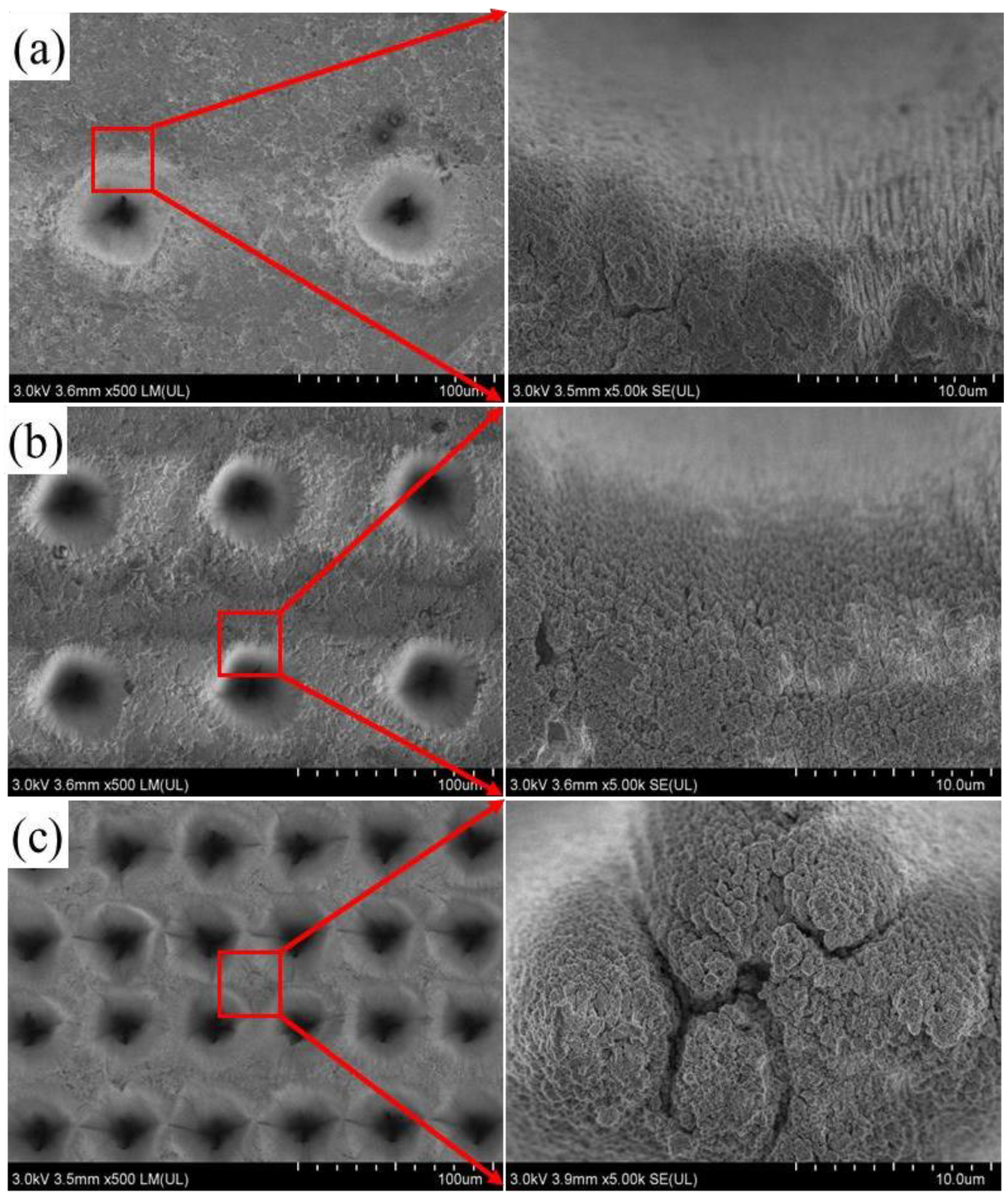
Figure 3.
Micro- and nanomorphology of (a) C1, (b) C2, (c) C3.
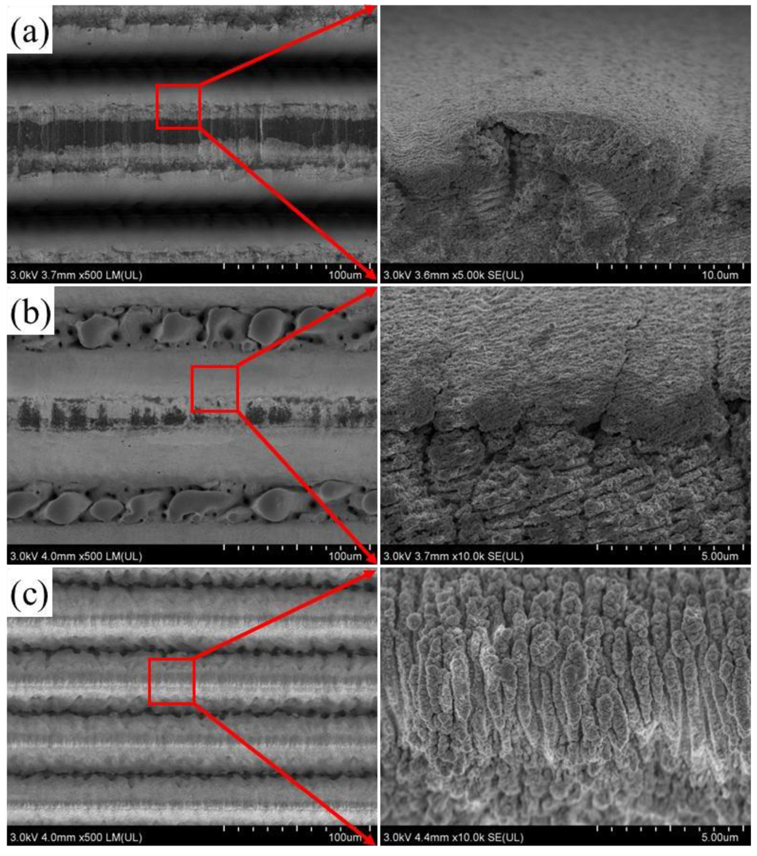
Figure 4.
XPS spectrum: (a–c) are C, O, and Ti high-resolution spectra of the circular pit structure; (d–f) are the C, O, and Ti high-resolution spectra of the grooves.
Figure 4.
XPS spectrum: (a–c) are C, O, and Ti high-resolution spectra of the circular pit structure; (d–f) are the C, O, and Ti high-resolution spectra of the grooves.
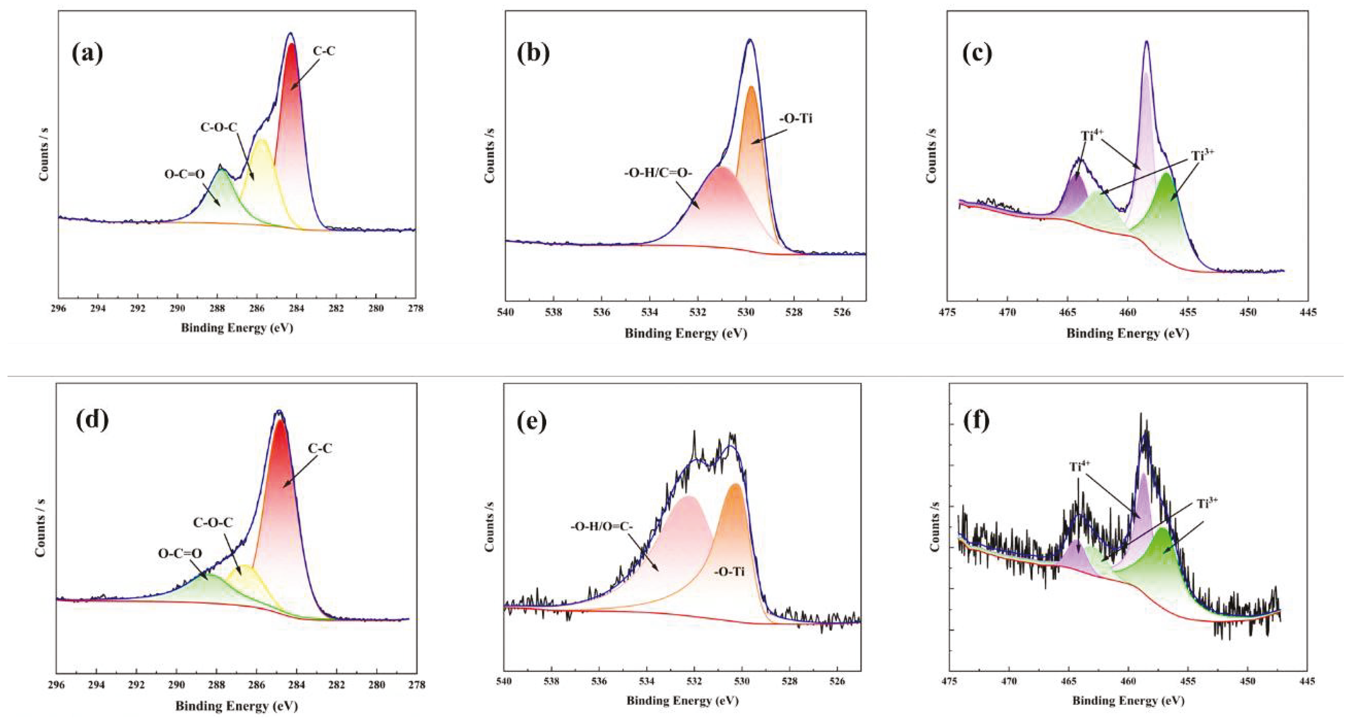
Figure 5.
Contact angle of (a) Ti and (b) Ti after modification.

Figure 6.
Contact angle of (a) K1, (b) K2, (c) K3, (d) C1, (e) C2, and (f) C3.

Figure 7.
Contact angle of (a) Kt1, (b) Kt2, (c) Kt3, (d) Ct1, (e) Ct2, and (f) Ct3.
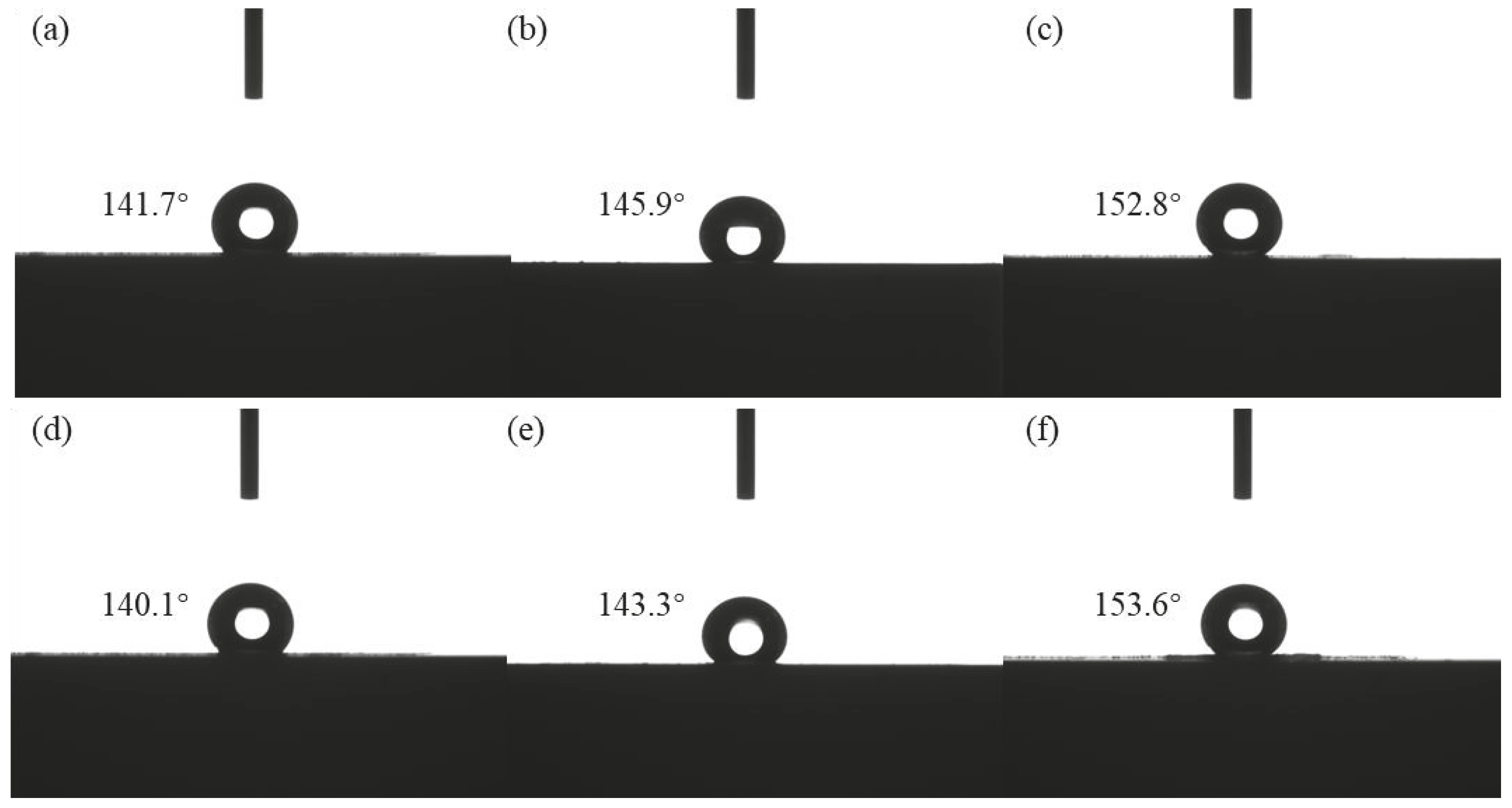
Figure 8.
Friction coefficients of textured surfaces with different densities: (a) circular pit structure, (b) groove structure.
Figure 8.
Friction coefficients of textured surfaces with different densities: (a) circular pit structure, (b) groove structure.

Figure 9.
Contour lines of abrasion marks on structures with different weave densities (a). Circular pit structure, (b) groove structure.
Figure 9.
Contour lines of abrasion marks on structures with different weave densities (a). Circular pit structure, (b) groove structure.

Figure 10.
Wear-resistant mechanism of (a) circular pits and (b) grooves.


Table 1.
The parameter of textured Ti.
| Denoted Name | Shape | Diameter | Depth | Density |
|---|---|---|---|---|
| K1 | 45 | 50 | 10% | |
| K2 | Circle | 45 | 50 | 20% |
| K3 | 45 | 50 | 90% | |
| C1 | 50 | 50 | 50% | |
| C2 | Groove | 50 | 50 | 70% |
| C3 | 50 | 50 | 90% |
Table 2.
The parameters of textured Ti after chemical modification.
| Denoted Name | Shape | Diameter | Depth | Density |
|---|---|---|---|---|
| Kt1 | 45 | 50 | 10% | |
| Kt2 | Circle | 45 | 50 | 20% |
| Kt3 | 45 | 50 | 90% | |
| Ct1 | 50 | 50 | 50% | |
| Ct2 | Groove | 50 | 50 | 70% |
| Ct3 | 50 | 50 | 90% |
Table 3.
Comparison of contact angle data for different structures on Ti surface.
| Ti Substrate | K1 | K2 | K3 | C1 | C2 | C3 | |
| Contact angle | 66.5° | 119.4° | 120.5° | 131.6° | 110.3° | 119.6° | 122.7° |
| Ti Substrate | Kt1 | Kt2 | Kt3 | Ct1 | Ct2 | Ct3 | |
| Contact angle after modification | 94.4° | 141.7° | 145.9° | 152.8° | 140.1° | 143.3° | 153.6° |
Table 4.
Comparison of the Ra and Rq for different structures on Ti surface.
| Ti Substrate | K1 | K2 | K3 | C1 | C2 | C3 | |
| Ra | 1.3 ± 0.04 | 1.5 ± 0.05 | 1.6 ± 0.06 | 1.8 ± 0.03 | 1.6 ± 0.07 | 1.7 ± 0.04 | 1.9 ± 0.05 |
| Rq | 1.4 ± 0.07 | 1.6 ± 0.06 | 1.7 ± 0.07 | 1.9 ± 0.04 | 1.7 ± 0.08 | 1.8 ± 0.05 | 2.0 ± 0.06 |
| Ti Substrate | Kt1 | Kt2 | Kt3 | Ct1 | Ct2 | Ct3 | |
| Ra after modification | 1.4 ± 0.01 | 1.6 ± 0.08 | 1.7 ± 0.05 | 2.0 ± 0.07 | 1.7 ± 0.02 | 1.8 ± 0.06 | 2.0 ± 0.03 |
| Rq after modification | 1.5 ± 0.03 | 1.7 ± 0.09 | 1.8 ± 0.02 | 2.1 ± 0.09 | 1.8 ± 0.05 | 1.9 ± 0.08 | 2.1 ± 0.04 |
Disclaimer/Publisher’s Note: The statements, opinions and data contained in all publications are solely those of the individual author(s) and contributor(s) and not of MDPI and/or the editor(s). MDPI and/or the editor(s) disclaim responsibility for any injury to people or property resulting from any ideas, methods, instructions or products referred to in the content. |
© 2024 by the authors. Licensee MDPI, Basel, Switzerland. This article is an open access article distributed under the terms and conditions of the Creative Commons Attribution (CC BY) license (https://creativecommons.org/licenses/by/4.0/).
Share and Cite
MDPI and ACS Style
Hou, Y.; Guo, W.; Sun, P.; Zhang, Y.; Ding, T.; Xing, Z.; Yang, S. Study on the Wettability and Abrasion Resistance of Ultrafast-Laser-Textured Ti Surface. Coatings 2024, 14, 516. https://doi.org/10.3390/coatings14040516
AMA Style
Hou Y, Guo W, Sun P, Zhang Y, Ding T, Xing Z, Yang S. Study on the Wettability and Abrasion Resistance of Ultrafast-Laser-Textured Ti Surface. Coatings. 2024; 14(4):516. https://doi.org/10.3390/coatings14040516
Chicago/Turabian StyleHou, Yuankun, Weiling Guo, Pengyuan Sun, Yanfang Zhang, Tong Ding, Zhiguo Xing, and Sefei Yang. 2024. "Study on the Wettability and Abrasion Resistance of Ultrafast-Laser-Textured Ti Surface" Coatings 14, no. 4: 516. https://doi.org/10.3390/coatings14040516
Note that from the first issue of 2016, this journal uses article numbers instead of page numbers. See further details here.