.jpg)
Anticorrosion Method Combining Impressed Current Cathodic Protection and Coatings in Marine Atmospheric Environment


1
College of Chemistry and Environment, Guangdong Ocean University, Zhanjiang 524088, China
2
College of Mechanical Engineering, Guangdong Ocean University, Zhanjiang 524088, China
*
Author to whom correspondence should be addressed.
Coatings 2024, 14(5), 524; https://doi.org/10.3390/coatings14050524
Submission received: 25 March 2024
/
Revised: 22 April 2024
/
Accepted: 22 April 2024
/
Published: 24 April 2024
(This article belongs to the Special Issue Investigation on Corrosion Behaviour of Metallic Materials)
Abstract
:In this study, a new anticorrosion method combining impressed current cathodic protection (ICCP) with coatings that can be applied to marine atmospheric environments is proposed. As the corrosion medium fills the cracks and pores of the coating, an electrolyte film layer is inevitably formed on the metal surface. Therefore, a graphene conductive coating with excellent chemical inertness and shielding performance is selected as the intermediate coating to form an electrolytic cell system with a metal substrate serving as the cathode and a graphene coating serving as the auxiliary anode. By studying the surface corrosion morphologies and electrochemical signals of the coating samples at different protection potentials and coating thicknesses, the optimal potential is determined to be 0.6 V, and the optimal coating thickness is determined to be 20 μm. The samples protected by the joint method have lower corrosion rates and better anticorrosion performance than those protected by the coatings alone.
1. Introduction
To resist marine corrosion to the environment, marine structures use a variety of corrosion control methods based on coating protection methods [1,2]. Coatings, as the primary option for steel structure corrosion protection, effectively delay metal corrosion by covering the metal surface with a protective film, which acts as a barrier against external media. However, the presence of nanoscale pores in the coating itself and of micrometer- and millimeter-sized pores formed during painting and use can increase the air and water permeability of the coating [3,4]. The thin liquid film on the surface gradually penetrates the coatings, leading to failure of the coating and the inability to provide long-term protection [5]. Moreover, ICCP is a widely used anticorrosion technology in marine engineering that is mainly used to protect ships, pipelines, reinforced concrete, and other structures from corrosion [6,7,8]. ICCP has the advantages of a low cost, remote monitoring ability, and greenness/environmental protection ability. However, due to the lack of macroscopic continuous conductive electrolytes in the atmosphere, ICCP is rarely used in marine atmospheric environments [9]. Therefore, overcoming the limitations of individual protective techniques and meeting the diverse requirements remain pressing issues in the field of marine engineering.
Combining ICCP with coatings in an atmospheric environment and in a seawater environment can inhibit the generation of corrosion products in coating defects. These defects can delay coating failure, thereby improving the corrosion protection effect of marine engineering equipment in the atmospheric environment. Against this background, researchers have investigated combined corrosion prevention techniques. Refait [10] studied coupons alternately immersed in seawater and exposed to the atmosphere placed in the tidal zone. He attempted to create a localized environment to maintain the liquid electrolyte around the metal. However, this method is difficult to apply on a large scale in the atmospheric environment and is similar to traditional cathodic protection techniques. The key to achieving cathodic protection in the atmospheric environment is to create an ionic conductive state. Ge [11] applied a specifically formulated coating containing the solid electrolyte sodium alumina as the ionically conducting component. The coating not only isolates metal substrates from the atmospheric environment but also provides an electrical path for impressed currents. However, the preparation of coatings is relatively complex, which has prevented this technology from becoming widespread.
This paper proposes an anticorrosion method to enhance the corrosion protection of marine engineering equipment in the atmospheric environment. This approach can overcome the limitations of traditional ICCP and compensate for the weaknesses of coatings, which are not able to provide effective long-term protection. This protection system is based on the principle of using a microporous channel-filled electrolyte to combine ICCP with coatings. Graphene is composed of sp2-bonded carbon atoms densely packed in a honeycomb lattice. It presents a variety of properties, such as gas impermeability, chemical (acid/base/salt) resistance, a large aspect ratio, thermal stability, eco-friendliness, surface flexibility, and excellent mechanical properties [12]. Thus, graphene powder is chosen as the functional filler to prepare a graphene conductive coating. The graphene coating, as the intermediate coating of the sandwich composite coatings, has great anticorrosion performance, which is mainly due to the following two aspects. On the one hand, the graphene lattice can form a corrosion barrier on the metal surface, which can effectively prevent the penetration of corrosive media, thereby improving the corrosion resistance and the lifespan of the coating [13,14,15]. On the other hand, when coating cracks and pores appear, the corrosive medium permeates through the pores to the protected substrate surface, forming an electrolyte membrane layer [16,17]. This layer provides a pathway between the metal substrate and graphene conductive coating [18]. By applying ICCP to the substrate, an electrolytic cell system is formed, with the protected metal substrate serving as the cathode and graphene serving as the auxiliary anode. Since the auxiliary anodes are uniformly distributed on the metal surface, the potential distribution is relatively uniform. Cathodic protection can also be achieved with less electrolyte.
In this study, the anticorrosion performance of this joint method is evaluated by analyzing the surface corrosion morphologies and electrochemical signals of scratched and scratch-free samples exposed to a marine atmosphere for 20 days. Moreover, the coating degradation behaviors and metal corrosion states under different protection potential and coating thickness parameters are investigated to understand and improve the protection mechanisms of the novel method.
2. Materials and Methods
2.1. Materials and Specimens
Graphene powder with a diameter of 3~15 was purchased from Shenzhen Juzhan Materials Technology Co., Ltd. (Shenzhen, China). Waterborne epoxy resin and deionized water were supplied by Guangdong Kecheng Laboratory Equipment Co., Ltd. (Zhanjiang, China). Epoxy universal primer and polyurethane antifouling topcoat were supplied by Fuzhou Allgall Technology Co., Ltd. (Fuzhou, China).
The values of the corrosion development trend constants of Q235 carbon steel ranged from 0.7 to 1.5. It was greatly affected by environmental changes and could intuitively demonstrate the influences of changing the protection mechanism on the corrosion of the metal. Thus, the 150 mm × 100 mm × 5 mm long Q235 carbon steel plate (Table 1) was used as the metal material for research in this study.
First, the Q235 carbon steel was sequentially wet abraded with 280#, 500#, 800#, and 1000# grit carbide metallographic sandpapers, cleaned with anhydrous ethanol and acetone, and then air-dried. Next, the wire was welded to the substrate as a cathode lead. Then, the surface was evenly coated with the epoxy universal primer, graphene composite coating, and polyurethane antifouling topcoat. The graphene composite coating was manufactured by mixing graphene powder, waterborne epoxy resin, and deionized water at a ratio of 1:1:2. After mixing and stirring, the graphene powder was completely dispersed through ultrasonic waves, as shown in Figure 1. When the graphene coating was not dry, a conductive carbon fiber was attached to one side of the layer, and a wire was connected to the other side as an anode lead. Finally, a power supply was connected in series between the substrate and the graphene coating.
Because the coating always has a certain air permeability and water permeability, it cannot be completely isolated from the outside world [19,20]. The permeation of the electrolytes allows for the formation of pathways between the metal substrate and the graphene coating. Figure 2 shows the structure and working principle of the joint method.
2.2. Marine Atmospheric Exposure Site
Figure 3 shows that the samples were placed in the exposure field of Zhanjiang city, Donghai Island, Guangdong Province. A 20-day experiment in a marine atmospheric environment was conducted. Zhanjiang city is located in the southernmost part of mainland China, with a longitude of 109°31′~110°55′ E and a latitude of 20°~21°35′ N. This city includes the entire Leizhou Peninsula and part of the northern peninsula. The climate of this city is a maritime monsoon climate, with an average annual temperature of approximately 22.8 °C and an annual rainfall of approximately 2000 mm.
2.3. Electrochemical Characterization
The electrochemical tests used a traditional three-electrode system (Figure 4). In this system, we used a silver chloride electrode serving as the reference electrode, a 2 cm × 2 cm platinum plate serving as the counter electrode, a sample serving as the working electrode, and a 3.5 wt% NaCl solution serving as the electrolyte. The test area was 19.6 mm2.
EIS was carried out at the open-circuit potential (OCP), and the amplitude of the AC excitation signal was 10 mV in the frequency range of 105~10−2 Hz. Then, the acquired ElS data were fitted with an equivalent circuit using Zview 2.7 software. To minimize the influences of the surrounding environment on the measurement signals, the samples were placed in a Faraday cage during the measurement process.
The open-circuit potential test time was 15 min. The scanning interval for the potentiodynamic polarization test was 0.05 V with a scanning rate of 0.1 mV/s.
3. Results and Discussion
3.1. Determination of the Optimum Protection Potential
In this experiment, an impressed voltage system of two coating samples connected in series was adopted, and one coating sample surface was carved with an X-shaped scratch. A potentiometer was connected in series in this circuit to adjust the voltage. The voltages of each group of circuits were fixed at 0 V, 0.6 V, 1.2 V, and 1.8 V, indicating that the impressed protection voltages of a single coating sample were 0 V, 0.3 V, 0.6 V, and 0.9 V. After the samples were retrieved, the surface morphologies of the scratch samples were recorded with the infinite-focus three-dimensional microscope and camera. Then, the impedances of the scratch-free samples were recorded by an electrochemical workstation and Tait cell kit.
Figure 5 shows the surface corrosion morphologies of the scratched samples before and after peeling off the coating under different protection voltages. The impressed voltages of the samples from left to right were 0 V, 0.3 V, 0.6 V, and 0.9 V. According to the image before peeling off the coating, the corrosion products that accumulated at the scratches of the sample with an impressed voltage of 0.6 V were the least abundant and did not spread to the coating. The corrosion degree of the sample with an impressed voltage of 0.3 V was the second highest. For the samples with impressed voltages of 0 V and 0.9 V, the corrosion products were highly enriched on the scratch. The corrosion products of the samples in the marine atmospheric environment diffuse with the aid of water, so there were many obvious corrosion products on the coating surfaces around the scratches. After the coating was stripped by a muffle furnace at a high temperature, the corrosion of the substrate under the coating could be detected by the infinite-focus three-dimensional microscope. The samples without an impressed voltage not only exhibited severe corrosion at the scratch but the substrate also had uniform corrosion. The corrosion rust spots were uniformly distributed over a large area of the substrate. Obviously, when the impressed voltage was 0 V or 0.9 V, the surface of the sample substrate had the most corrosion marks, followed by the surface of the sample with an impressed voltage of 0.3 V. The surface of the sample with an impressed voltage of 0.6 V had the fewest corrosion marks. This finding demonstrated that the best protective effect of the substrate was approximately 0.6 V for the scratched coating sample.
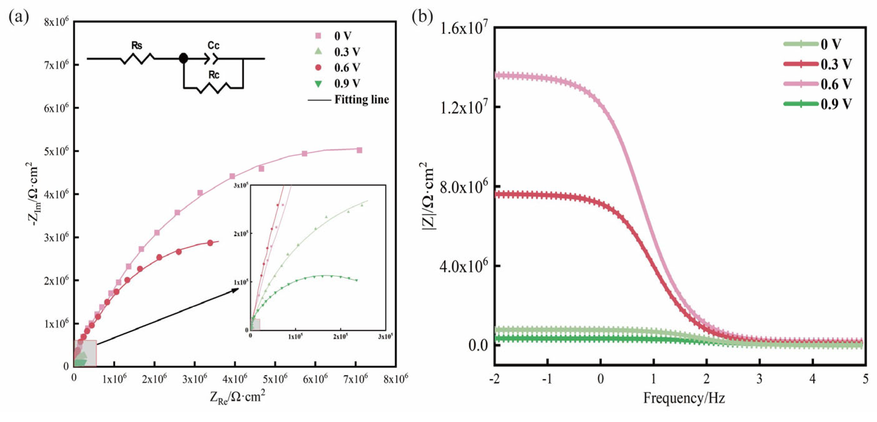
Figure 6 shows the EIS images of the scratch-free samples under different protection voltages. In the proposed system, the metal substrate and the graphene conductive coating underwent galvanic corrosion under impressed voltage. Although the metal substrate received electrons, the graphene coating used as an auxiliary anode suffered some deterioration during use, resulting in an overall reduction in impedance [21]. The Nyquist diagram (Figure 6a) shows that the impedances of the samples with impressed voltages were lower than the sample without impressed voltages. Moreover, the impedance of the impressed voltage samples did not linearly change with the impressed voltage. When the impressed voltage was 0.6 V, the impedance was closest to the sample without impressed voltages and much greater than the samples with impressed voltages of 0.6 V and 0.9 V. Thus, a high impressed voltage effectively protected the metal substrate better and increased the degradation of the graphene coating.
Typically, the impedance at a low frequency () is one of the main parameters used to evaluate the corrosion resistance of a coating sample. This phenomenon is directly related to the corrosion resistance of the coating sample. A high impedance would indicate an enhanced corrosion resistance of the coating. According to the Bode diagram (Figure 6b), when the frequency was 0.01 Hz, the barrier ability decreased in the following order: 0.6 V 0.3 V 0 V 0.9 V. Thus, the most suitable voltage was approximately 0.6 V when the coating was intact. This voltage would not damage the coating protection technology and would cause the least interference.
3.2. Determination of the Optimal Graphene Coating Thickness
In this experiment, the thicknesses of the graphene coatings in the five coating samples were controlled to 10 , 15 , 20 , 25 , and 30 . The dry film thickness of each coating was measured and averaged over five measurements to ensure that the margin of error was maintained at 2 . Each coating sample was carved with an X-shaped scratch. Then, the samples were split into two groups, one with an impressed voltage of 0.6 V and the other without impressed voltage. The samples were tested for their open-circuit potential, and potentiodynamic polarization testing was performed by an electrochemical workstation and the Tait cell kit after retrieval.
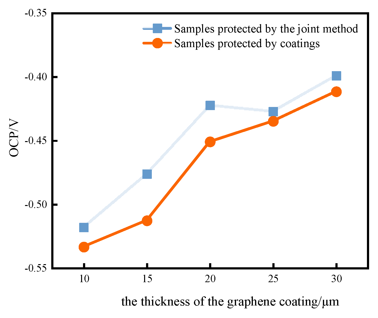
Figure 7 shows the open-circuit potentials of the scratched samples with different coating thicknesses. In general, the greater the risk of water and corrosive media diffusing into the interface between the coating and the metal, the more susceptible the coating is to corrosion. The open-circuit potentials of the samples with impressed voltages were greater than the samples without impressed voltages. Thus, it can be observed that the presence of ICCP could enhance the corrosion resistance of the coating samples, and the novel anticorrosion method could function in a marine atmospheric environment. In addition, the figure shows that the overall open-circuit potential tended to increase as the thickness of the graphene coating increased. At thicknesses of 10~20 , the open-circuit potential moved significantly in a positive direction. At thicknesses of 20~30 , the change in the open-circuit potential became flat. Therefore, it was not possible to improve the protective performance of the combined anticorrosion system by further increasing the thickness.
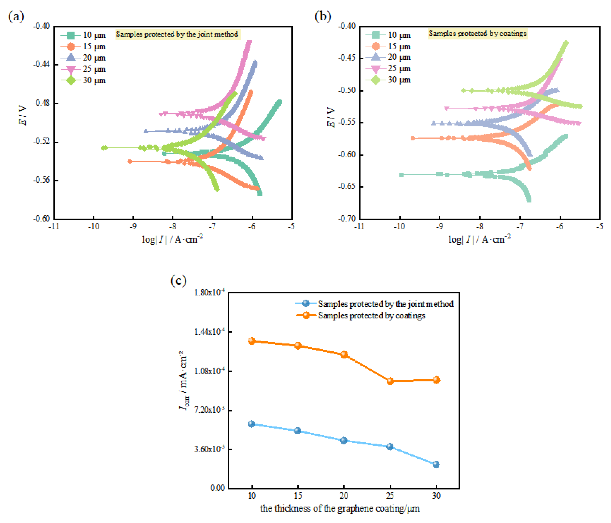
Figure 8 shows the potentiodynamic polarization curves and the corrosion current density (Icorr) variations. As the thickness of the graphene coating increased, the Icorr values of the samples without impressed voltages increased, ranging from 1.36 × 10⁻⁴ mA/cm2 to 9.87 × 10⁻⁴ mA/cm2, while the Icorr values of the samples with impressed voltages significantly decreased, ranging from 2.15 × 10⁻⁵ mA/cm2 to 5.88 × 10⁻⁵ mA/cm2. Because the graphene coating effectively inhibited corrosion, its atomic lattice could prevent the intercalation of oxidizing species and the penetration of corrosive media by virtue of its impermeability [22]. The thicker the coating was, the more difficult it was for corrosion products to reach the metal substrate. As a result, the Icorr tended to decrease overall. However, if defects were present, the graphene layer lost the benefit of shielding protection [23]. Cathodic protection delivered a current to the scratched area in this case, reducing the number of active sites or forming a protective film. Moreover, the electrolyte membrane layer, which was present in the coating cracks and pores, protected the scratch-free site. As a result, the metal at the scratch had a low corrosion rate and was in a protected state [24]. Overall, the samples with impressed voltages had better corrosion resistance than the samples without impressed voltages.
4. Conclusions
- (1)
- In this paper, a novel corrosion prevention method that effectively combines the advantages of coatings and ICCP (impressed current cathodic protection) technology is proposed. The method constructs a sandwich composite coating system. The microscopic electrolyte membrane layer provides a pathway between the metal substrate and the conductive graphene coating, allowing ICCP to improve the corrosion protection of equipment in the marine atmospheric environment.
- (2)
- Wherever the coatings are stripped before and after, the scratched sample with an impressed voltage of 0.6 V has the least corrosion, while the samples with impressed voltages of 0 V and 0.9 V have the most severe corrosion. The graphene conductive coating serving as the auxiliary anode suffers to an extent with increasing impressed voltage. However, the resistance of the scratch-free sample with an impressed voltage of 0.6 V is similar to the sample without an impressed voltage, and the protection effect is the greatest. The results show that 0.6 V can effectively protect the carbon steel substrate for a long time.
- (3)
- As the thickness of the graphene coating increases, it becomes increasingly difficult for the corrosion products to reach the metal substrate; thus, the open-circuit potentials shift in the positive direction. Moreover, the scratched samples with impressed voltages have higher open-circuit potentials and lower corrosion current densities than those without impressed voltages. This further confirms that the method provides excellent corrosion protection. Considering the efficiency of corrosion prevention methods and the cost of application, the protective characteristics of the combined anticorrosion system are ensured by the optimal thickness of the graphene coating of 20 μm.
Author Contributions
Conceptualization, P.D. and J.H.; methodology, P.D.; software, H.H. and L.Z.; validation, J.S., H.H. and L.Z.; formal analysis, J.S.; investigation, L.Z.; resources, J.H.; data curation, J.S. and L.Z.; writing—original draft preparation, J.S.; writing—review and editing, J.S.; visualization, P.D.; supervision, H.H.; project administration, J.H.; funding acquisition, J.H. All authors have read and agreed to the published version of the manuscript.
Funding
The authors were sincerely grateful for the financial support from the Natural Science Foundation of Guangdong Province (No. 2021A1515012129) and the Science & Technology Development Foundation of Zhanjiang (No. 2022A01029).
Institutional Review Board Statement
Not applicable.
Informed Consent Statement
Not applicable.
Data Availability Statement
Data are contained within the article.
Conflicts of Interest
The authors declare no conflicts of interest.
References
- Li, X.; Zhang, D.; Liu, Z.; Li, Z.; Du, C.; Dong, C. Materials science: Share corrosion data. Nature 2015, 527, 441–442. [Google Scholar] [CrossRef] [PubMed]
- Deshpande, P.; Kolekar, A.; Bhopale, A.; Kalendova, A.; Kohl, M. ICCP of mild steel in association with zinc based paint coating. Mater. Today Proc. 2022, 50, 1660–1665. [Google Scholar] [CrossRef]
- Wu, W.; Zeng, Z.; Cheng, X.; Li, X.; Liu, B. Atmospheric corrosion behavior and mechanism of a Ni-Advanced weathering steel in simulated tropical marine environment. J. Mater. Eng. Perform. 2017, 26, 6075–6086. [Google Scholar] [CrossRef]
- Price, J.S.; Figueira, B.R.; Soucek, D.M. Corrosion protection systems and fatigue corrosion in offshore wind structures: Current status and future perspectives. Coatings 2017, 7, 25. [Google Scholar] [CrossRef]
- Zhang, H.; Sun, W.; Wang, L.; Wang, J.; Wang, S.; Liu, G. A mechanically and chemically stable superhydrophobic coating for preventing marine atmospheric corrosion. Surf. Interfaces 2021, 27, 101537. [Google Scholar] [CrossRef]
- Mitolo, M.; Pettinger, A. Interactions between cathodically protected pipelines and grounding systems. IEEE Trans. Ind. Appl. 2016, 52, 3694–3698. [Google Scholar] [CrossRef]
- Guo, B.; Qiao, G.; Li, D.; Ou, J. Multi-species reactive transport modeling of electrochemical corrosion control in saturated concrete structures including electrode reactions and thermodynamic equilibrium. Constr. Build. Mater. 2021, 278, 122228. [Google Scholar] [CrossRef]
- Feng, R.; Wang, J.; Zhu, J.; Dong, Z. Fatigue behavior of corroded reinforced concrete continuous beams with multi-intervention system. Eng. Struct. 2021, 231, 111748. [Google Scholar] [CrossRef]
- Anwar, S.M.; Sujitha, B.; Vedalakshmi, R. Light-weight cementitious conductive anode for ICCP of steel reinforced concrete application. Constr. Build. Mater. 2014, 71, 167–180. [Google Scholar] [CrossRef]
- Refait, P.; Jeannin, M.; Sabot, R.; Antony, H.; Pineau, S. Corrosion and cathodic protection of carbon steel in the tidal zone: Products, mechanisms and kinetics. Corros. Sci. 2015, 90, 375–382. [Google Scholar] [CrossRef]
- Ge, D.; Zhang, Z.; Zhang, C.; Xu, N. Novel technique of impressed current cathodic protection in atmospheric environments. Br. Corros. J. 2013, 24, 265–268. [Google Scholar]
- Ashok, S.S.K.; Shahid, B.; Ramesh, K.; Ramesh, S. New perspectives on graphene/graphene oxide based polymer nanocomposites for corrosion applications: The relevance of the graphene/polymer barrier coatings. Prog. Org. Coat. 2021, 154, 106215. [Google Scholar]
- Bunch, J.S.; Verbridge, S.S.; Alden, J.S.; Van Der Zande, A.M.; Parpia, J.M.; Craighead, H.G.; McEuen, P.L. Impermeable atomic membranes from graphene sheets. Nano Lett. 2008, 8, 2458–2462. [Google Scholar] [CrossRef] [PubMed]
- Berry, V. Impermeability of graphene and its applications. Carbon 2013, 62, 1–10. [Google Scholar] [CrossRef]
- Papageorgiou, G.D.; Kinloch, A.I.; Young, J.R. Mechanical properties of graphene and graphene-based nanocomposites. Prog. Mater. Sci. 2017, 90, 75–127. [Google Scholar] [CrossRef]
- Chen, Y.; Wu, L.; Yao, W.; Wu, J.; Xiang, J.; Dai, X.; Wu, T.; Yuan, Y.; Wang, J.; Jiang, B.; et al. Development of metal-organic framework (MOF) decorated graphene oxide/MgAl-layered double hydroxide coating via microstructural optimization for anticorrosion micro-arc oxidation coatings of magnesium alloy. J. Mater. Sci. Technol. 2022, 130, 12–26. [Google Scholar] [CrossRef]
- Aidin, B.K.; Benyamin, Y.; Masoud, M. Effect of ZnO pore-sealing layer on anticorrosion and in-vitro bioactivity behavior of plasma electrolytic oxidized AZ91 magnesium alloy. Mater. Lett. 2020, 258, 126779. [Google Scholar]
- Yang, Z.; Che, J.; Zhang, Z.; Yu, L.; Hu, M.; Sun, W.; Gao, W.; Fan, J.; Wang, L.; Liu, G. High-efficiency graphene/epoxy composite coatings with outstanding thermal conductive and anticorrosion performance. Compos. Part A 2024, 181, 108152. [Google Scholar] [CrossRef]
- Cui, G.; Bi, Z.; Zhang, R.; Liu, J.; Yu, X.; Li, Z. A comprehensive review on graphene-based anti-corrosive coatings. Chem. Eng. J. 2019, 373, 104–121. [Google Scholar] [CrossRef]
- Zhang, F.; Ju, P.; Pan, M.; Zhang, D.; Huang, Y.; Li, G.; Li, X. Self-healing mechanisms in smart protective coatings: A review. Corros. Sci. 2018, 144, 74–88. [Google Scholar] [CrossRef]
- Quezada-Renteria, A.J.; Chazaro-Ruiz, F.L.; Rangel-Mendez, R.J. Poorly conductive electrochemically reduced graphene oxide films modified with alkyne chains to avoid the corrosion-promoting effect of graphene-based materials on carbon steel. Carbon 2020, 167, 512–522. [Google Scholar] [CrossRef]
- Zhang, R.; Yu, X.; Yang, Q.; Cui, G.; Li, Z. The role of graphene in anticorrosion coatings: A review. Constr. Build. Mater. 2021, 294, 123613. [Google Scholar] [CrossRef]
- Zhou, S.; Yao, W.; Wang, Z.; Ma, L.; Lu, Z.; Hou, C. The first-principles calculations to explore the mechanism of oxygen diffusion on vacancy defective graphene in marine environment. Appl. Surf. Sci. 2020, 525, 136585. [Google Scholar] [CrossRef]
- Wang, X.; Wang, Z.; Chen, Y.; Song, X.; Yang, Y. Effect of a DC Stray Current on the corrosion of X80 pipeline steel and the cathodic disbondment behavior of the protective 3PE coating in 3.5% NaCl solution. Coatings 2019, 9, 29. [Google Scholar] [CrossRef]
Figure 1.
SEM image of graphene/epoxy coating.
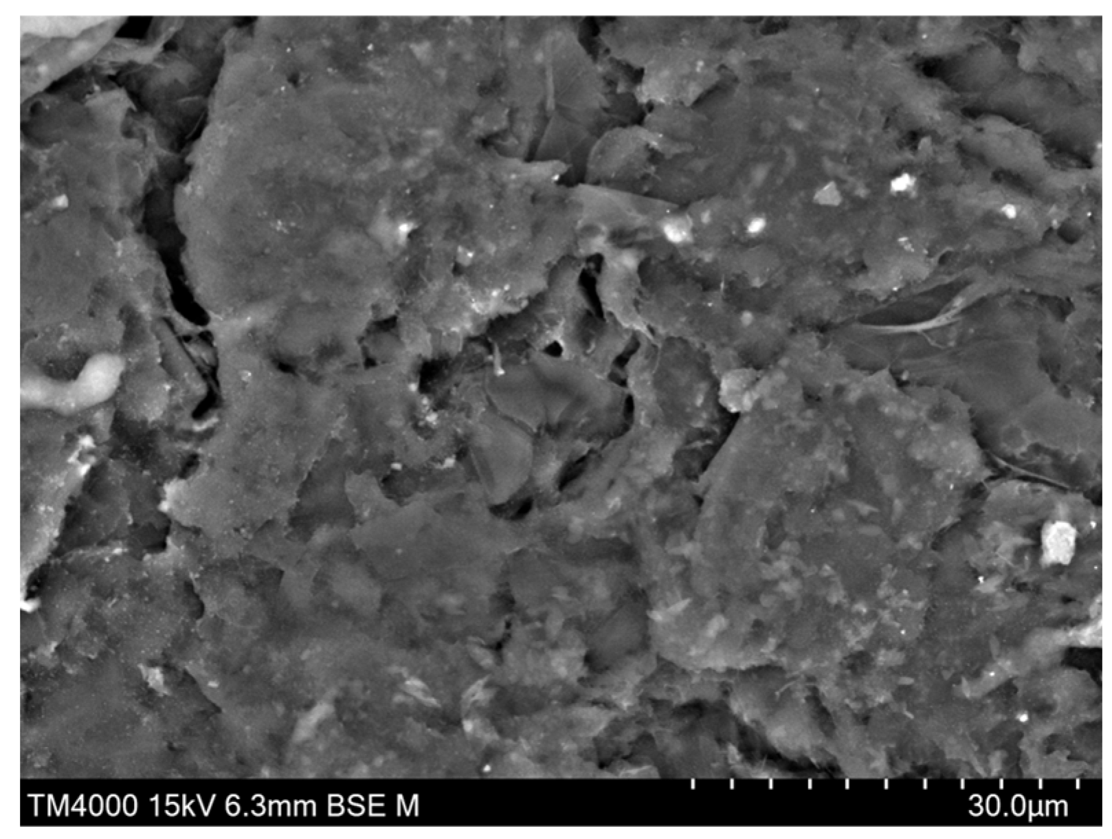
Figure 2.
Structure and principle of the joint method.
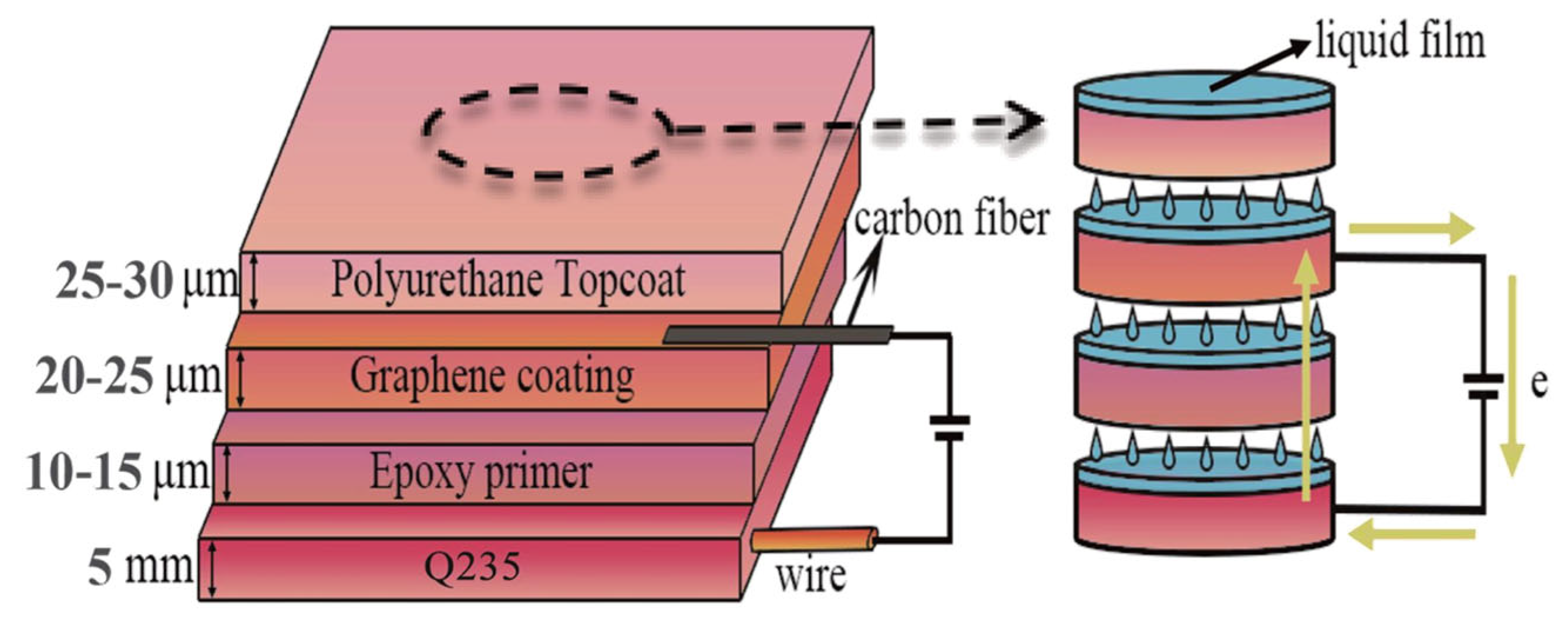
Figure 3.
Experimental site.
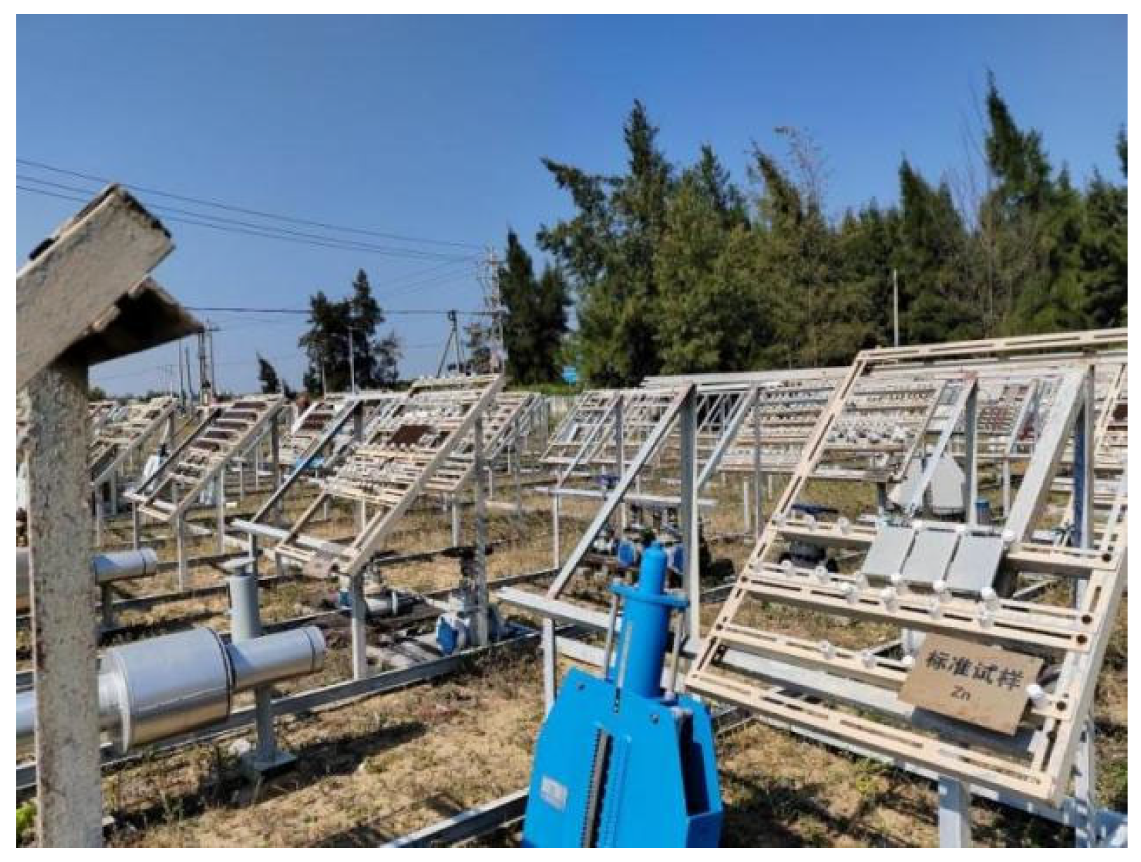
Figure 4.
Schematic diagram of the coating sample test system.

Figure 5.
Surface morphologies of the scratched samples before and after peeling off the coating under different protection voltages.
Figure 5.
Surface morphologies of the scratched samples before and after peeling off the coating under different protection voltages.
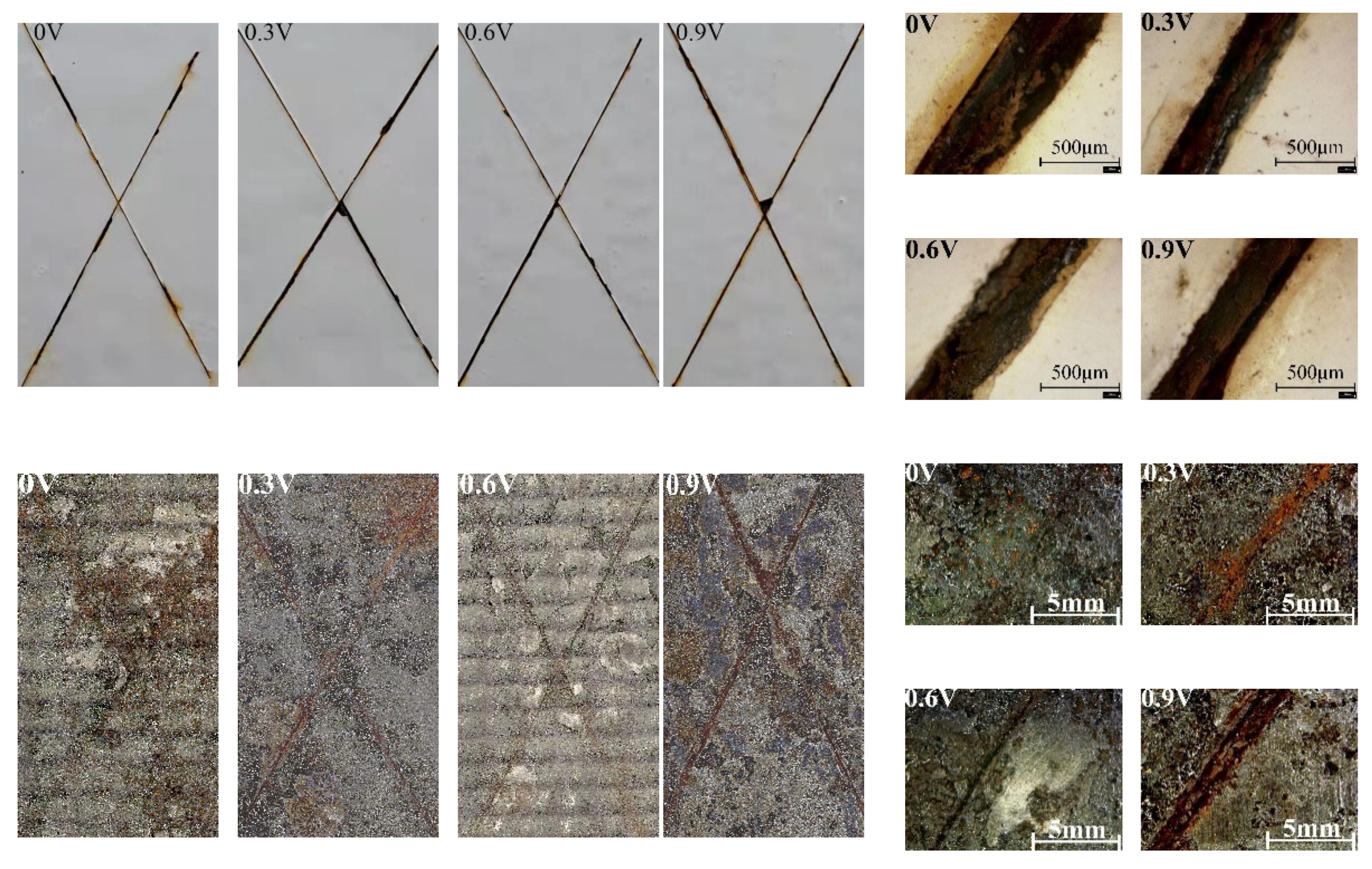
Figure 6.
Nyquist (a) and Bode (b) impedance plots of scratch-free samples under different protection voltages.
Figure 6.
Nyquist (a) and Bode (b) impedance plots of scratch-free samples under different protection voltages.

Figure 7.
Open-circuit potentials of the scratched coating samples with different thicknesses.

Figure 8.
Potentiodynamic polarization curves (a,b) and corrosion current density variations (c) in scratched coating samples at different thicknesses.
Figure 8.
Potentiodynamic polarization curves (a,b) and corrosion current density variations (c) in scratched coating samples at different thicknesses.

Table 1.
Chemical composition of material.
| Element wt (%) | ||||||||
|---|---|---|---|---|---|---|---|---|
| Material | C | Si | Mn | P | S | Cr | Ni | Cu |
| Q235 | 0.15 | 0.19 | 0.5 | 0.023 | 0.015 | ≤0.3 | ≤0.3 | ≤0.3 |
Disclaimer/Publisher’s Note: The statements, opinions and data contained in all publications are solely those of the individual author(s) and contributor(s) and not of MDPI and/or the editor(s). MDPI and/or the editor(s) disclaim responsibility for any injury to people or property resulting from any ideas, methods, instructions or products referred to in the content. |
© 2024 by the authors. Licensee MDPI, Basel, Switzerland. This article is an open access article distributed under the terms and conditions of the Creative Commons Attribution (CC BY) license (https://creativecommons.org/licenses/by/4.0/).
Share and Cite
MDPI and ACS Style
Deng, P.; Shangguan, J.; Hu, J.; Huang, H.; Zhou, L. Anticorrosion Method Combining Impressed Current Cathodic Protection and Coatings in Marine Atmospheric Environment. Coatings 2024, 14, 524. https://doi.org/10.3390/coatings14050524
AMA Style
Deng P, Shangguan J, Hu J, Huang H, Zhou L. Anticorrosion Method Combining Impressed Current Cathodic Protection and Coatings in Marine Atmospheric Environment. Coatings. 2024; 14(5):524. https://doi.org/10.3390/coatings14050524
Chicago/Turabian StyleDeng, Peichang, Juyu Shangguan, Jiezhen Hu, Huan Huang, and Lingbo Zhou. 2024. "Anticorrosion Method Combining Impressed Current Cathodic Protection and Coatings in Marine Atmospheric Environment" Coatings 14, no. 5: 524. https://doi.org/10.3390/coatings14050524
Note that from the first issue of 2016, this journal uses article numbers instead of page numbers. See further details here.