Magnetic Properties and Microstructure of FePt(BN, Ag, C) Films

Department of Materials Science and Engineering, National Chung Hsing University, Taichung 40227, Taiwan
*
Author to whom correspondence should be addressed.
Coatings 2018, 8(10), 358; https://doi.org/10.3390/coatings8100358
Submission received: 24 August 2018
/
Revised: 1 October 2018
/
Accepted: 4 October 2018
/
Published: 9 October 2018
(This article belongs to the Special Issue Advanced Thin Films Deposited by Magnetron Sputtering)
Abstract
:The microstructure and magnetic properties of FePt(BN, Ag, C) granular films grown on the MgTiON intermediate layer with and without the MoC inserting layer were studied. Without the MoC inserting layer, the 6 nm thick FePt film is continuous, which favors the domain wall motion magnetization reversal process and shows a lower out-of-plane coercivity (Hc) value of 6.7 kOe. The FePt(BN, Ag, C) granular film was grown in ball- and square-like grains with an almost vertical contact angle, and the out-of-plane coercivity (Hc) was increased to 15.5 kOe. When the MoC with a thickness of 3 nm was capped on the MgTiON intermediate layer, the FePt grains with and without (BN, Ag, C) segregants were both formed in large trapezoidal islands with a low contact angle morphology. The out-of-plane Hc value changed from 14.9 to 13.2 kOe and the reduced coercivity was due to larger grain sizes and a lower ordering degree of the FePt(BN, Ag, C) film.
1. Introduction
The L10 FePt film with (001) texture, which is a promising heat assisted magnetic recording media tool (HAMR) with a high magnetocrystalline anisotropy (Ku) of 5 × 10⁷ erg/cm3, and the prototype of FePt media are currently being evaluated in industry [1,2,3,4]. The proper segregants are important terms for FePt media and have high aspect ratio columnar grains and an in-plane uniform granular grains structure. The (Ag, C) segregants were co-sputtered with FePt film in the early study [5]. The carbon segregant shows strong phase separation ability and can easily interrupt the FePt columnar grain growth laterally. The FePtC film shows a uniform in-plane granular grains structure but with the spherical grains and second nucleated FePt layer (t > 6 nm) in cross-sectional TEM images [6]. In addition to the C single segregant, the transition-metal oxide segregants were also required and have been extensively studied before now [7,8,9]. However, the addition of all the oxide segregants deteriorated the ordering degree, perpendicular anisotropy and out-of-plane coercivity of FePt film [7]. Only the Cr2O3 segregant shows less degradation of out-of-plane coercivity due to a lower cohesive energy and a positive mixing enthalpy [7]. For chemical electronegative oxide segregants such as GeO2 and SiO2, there are more covalent bonds which should also be considered to maintain the ordering and orientation of FePt grains during growth [10]. Non-oxide segregants such as nitride, and FePt segregant, the FePtC/FePt(BN)/FePtC trilayers and the FePt-SiNx-C film which were all studied, are still not fully understood [11,12]. The FePt layer with the BN segregant may impart less of a spherical shape on magnetic grains and out of plane coercivity as compared to carbon- and oxide-segregants, respectively. Different stacks of FePtC/FePt(BN, C) layers with different compositional gradients will also influence the final morphology and magnetic properties of grains. The BN with lower electronegativity (1.0) as compared to GeO2 (2.1), and SiO2 (1.9), was used as a segregant to decrease the strong phase separation ability of carbon to avoid the spherical grains. It’s suggested that the formation of bonding between C and BN. In this study, the (BN, C, Ag) multiple segregants with volumes ranging from 10%–30% were used and compared to the effects of the compositional MgTiON intermediate layer with and without the thin MoC inserted layer on the morphology of FePt grains. Due to the varied surface- and interface-energy, the FePt grains show a different morphology and contact angle on modified surfaces. The FePt(BN, C, Ag) film deposited on MgTiON (002)/CrRu (002) shows higher chemical ordering, higher (001) orientation and vertical contact angle of grains, as compared to our previous works which use 25–30 nm thick MoC (002) as the intermediate layer [13,14].
2. Materials and Methods
The FePt(6 nm)(BN, Ag, C)(x vol.%)/MoC(y nm)/MgTiON(30 nm)/CrRu/glass (x = 0, 10; y = 0, 3) films were deposited onto Corning (Eagle 2000, Corning Display Technologies, Taipei, Taiwan) glass substrates using a high-vacuum magnetron sputtering (Pbase = 5 × 10⁻⁷ Torr) under a working pressure of 10−3 Torr. The CrRu seed layer with a thickness of 80 nm was sputtered on glass substrate at 215 °C. The MgTiON intermediate layer with a thickness of 30 nm was deposited by using (Mg0.5Ti0.5)(O0.9N0.1) target at 435 °C. The thinner MoC inserting layer with a thickness of 3 nm was prepared by using Mo40C60 alloy target at 435 °C. Finally, the FePt film with a thickness of 6 nm was fixed and co-sputtered with 10 vol.% (BN, Ag, C) at 470 °C. (The volume concentration of (BN, Ag, C) was changed from 10 vol.% to 30 vol.%, and the optimal condition for FePt (001) texturing was 10 vol.%). The atomic chemical compositions of B, C, N, and Ag were 15%, 51%, 25% and 9%, respectively, measured by energy dispersive spectrum (EDS). The reference sample (0, 0) was FePt film, prepared under the same condition but without (BN, Ag, or C) segregants and the MoC inserting layer. The crystallographic structure was investigated by X-ray diffraction (XRD), and θ/2θ diffraction patterns were collected using a standard X-ray diffractometer (D8 Discover, Bruker, Billerica, MA, USA). Both in-plane and out-of-plane field-dependent magnetization loops were measured at room temperature by using a superconducting quantum interference device (SQUID) magnetometer (MPMS-XL, Quantum design, San Diago, CA, USA). The film microstructure and the surface roughness were investigated by using transmission electron microscopy (TEM, JEOL JEM-2010, Tokyo, Japan) and atomic force microscopy (AFM, Veeco DI-3100, Plainview, NY, USA), respectively.
3. Results and Discussion
3.1. Structure for FePt(BN, Ag, C)/MoC/MgTiON/CrRu/Glass Films
Figure 1 shows the XRD patterns of the FePt(BN, Ag, C)(x vol.%)/MoC(y nm)/MgTiON/CrRu/glass films, (x, y) = (a) (0, 0), (b) (10, 0), (c) (0, 3), (d) (10, 3). The (002) textured CrRu seed layer and the MgTiON intermediate layer with similar relative integrated intensities are indexed. The 6 nm thick FePt films grown on MgTiON show L10 FePt (001) superlattice diffraction peaks and the (002) fundamental reflections in Figure 1. The chemical ordering parameter of bulk and thick FePt film without crystalline texture can be estimated from [(I(001)/I(002))/(I*(001)/I*(002))]1/2 [15,16]. For (001) textured and thin FePt film, the Lorentz and absorption factors were further corrected and the theoretical ratio of FePt (001) superlattice peak to (002) fundamental peak was calculated as a function of FWHM and thickness from FePt film [16]. In Figure 1, the integrated intensities of (001)/(002) peak ratios and ordering degrees were (a) 2.2 (0.79), (b) 1.9 (0.68), (c) 2.6 (0.84), and (d) 2.4 (0.76), respectively. The ordering degree of FePt film slightly deteriorated with (BN, Ag, C) segregants but increased with the MoC inserted layer.
3.2. Magnetic Properties of FePt/MoC/MgTiON/CrRu/Glass Films
In our previous work, the magnetic properties of FePt film improved significantly with the thinner MoC inserted layer due to the change in microstructure [7]. In this study, the (BN, Ag, C) segregants were co-sputtered with FePt film and the out-of-plane coercivity and nucleation field values of the FePt(BN, Ag, C) films were compensated with thinner MoC inserted layer. The corresponding out-of-plane and in-plane magnetic hysteresis loops of the FePt(BN, Ag, C)(x vol.%)/MoC(y nm)/MgTiON/CrRu/glass films, (x, y) = (a) (0, 0), (b) (10, 0), (c) (0, 3), (d) (10, 3), measured by SQUID with a maximum applied field of 5 T are shown in Figure 2. All the FePt and FePt(BN, Ag, C) films illustrate a perpendicular magnetization with in-plane hysteresis loop areas.
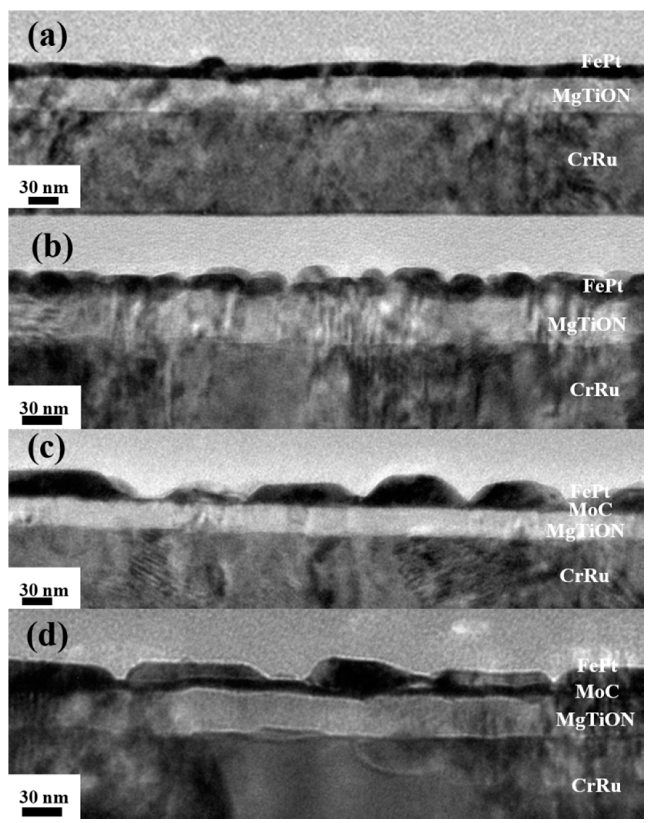
The 6-nm thick FePt film deposited on the MgTiON intermediate layer was a continuous layer, as evidenced in Figure 3a, and shows a lower out-of-plane Hc of 6.7 kOe in Figure 2a. With (BN, Ag, C) segregants, the FePt grains were separated into ball-like and square-like islands as shown in Figure 3b, and the out-of-plane coercivity (Hc) increased to 15.5 kOe in Figure 2b. Based on the microstructural morphology, the magnetization reversal process of FePt film changed from domain wall motion (incoherent behavior) to a more coherent-like behavior. The out-of-plane Hc was not high enough because of the reorientation of the perpendicular magnetic anisotropy of the FePt(BN, Ag, C) film towards the in-plane direction due to the decreased chemical ordering parameter, evidenced in Figure 1 [17]. With a 3-nm thick MoC inserted layer, the FePt film shows an out-of-plane Hc of 14.9 kOe in Figure 2c and the Hc decreased to 13.2 for the FePt(BN, Ag, C) film in Figure 2d. However, the FePt and FePt(BN, Ag, C) films with the MoC inserted layer show a higher number of nucleation fields with values of 6.8 kOe (>4.6 kOe in (a)) and 5.1 kOe (>3.2 kOe in (b)), and more square-like loops in Figure 2c,d which means that there is more uniformity of grains anisotropy (Ku,grain). The nucleation field in Figure 2b is significantly lower than in the other samples due to both the film morphology and the reorientation of the perpendicular magnetic anisotropy of FePt film towards the in-plane direction, due to the decreased chemical ordering parameters as evidenced in Figure 1 [17]. The diffraction peak around 49.06° in Figure 1b is the convolution of the Bragg peaks of the (200) fcc (at 47.75°) and (002) L10 (at 49.27°) phases, whereas the in-plane anisotropy is due to the contribution of a disordered soft magnetic fcc phase [17]. According to previous works [13,14] and current results in Figure 3c, the FePt film deposited on the MoC layer always forms the big trapezoidal islands due to the excess carbon diffused up to separate part of the FePt grains, and each island contains many interacted FePt grains as observed in Figure 7c,d in Reference [14]. As a result, adding the (BN, Ag, C) segregants only had a minor effect on the worm-line separation of FePt grains, and a negative effect on the FePt ordering degree and grains size. Finally, the FePt film shows a smaller out-of-plane Hc with (BN, Ag, C) segregants.
3.3. Microstructure of FePt/MoC/MgTiON/CrRu/Glass Films
In Figure 3a, the FePt film is more continuous on the MgTiON layer without the MoC inserted layer, and the MgTiON layer is also continuous on the CrRu alloy seed-layer. This suggests that FePt films prefer the layer growth mode (Frank-Van der Merwe) on the MgTiON intermediate layer which is also evidenced in reference [18].
With segregants (BN, Ag, C), the FePt grains were separated into different morphologies during growth. In Figure 3b, the ball- and square-like FePt grains range from 15 to 30 nm when observed. When the FePt film were deposited on the MoC layer with a thickness ranging from 3 to 25 nm [13,14], trapezoidal islands were always obtained as evidenced in Figure 3c.
In this work, the segregants (BN, Ag, C) with 10 vol.% were added to FePt films. However, the FePt grains were also agglomerated into the trapezoidal islands, as illustrated in Figure 3d, and the base length of the trapezoidal island was around 100 nm. This suggests that the FePt film prefer the island growth (Volmer-Weber growth mode) on the MoC(3 nm)/MgTiON intermediate layer even without segregants (BN, Ag, C), and that the lower interface energy between FePt/MoC (2.1/2.45) makes a small de-wetting (or contact) angle of around 47° as shown in Figure 4c.
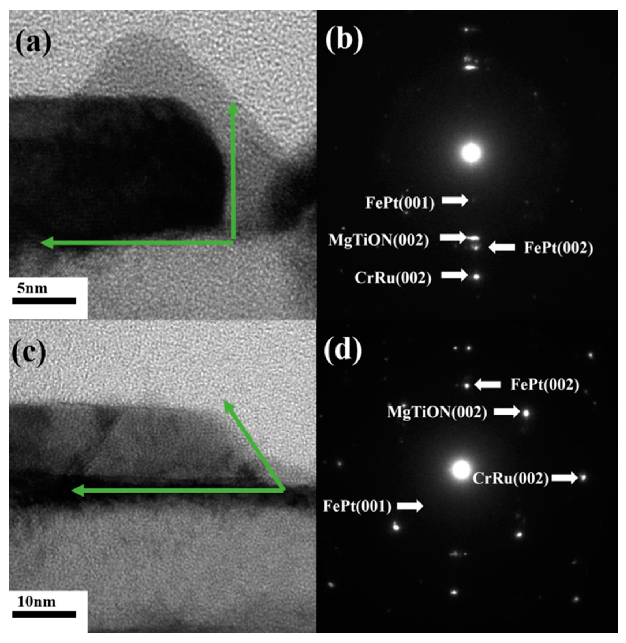
Figure 4 shows magnified cross-sectional TEM images and selected area diffraction (SAD) patterns of Figure 3b,d. In Figure 4a, the square-like FePt grains are observed with almost vertical contact angles, and the corresponding selected area diffraction (SAD) pattern is shown in Figure 4b. From SAD pattern, the FePt (001)/(002), CrRu (002), and MgTiON (002) were indexed. Figure 4c shows that the FePt grains agglomerated to form trapezoidal islands when the FePt film was deposited on the MoC inserted layer, and (d) illustrates the diffraction pattern. From the SAD pattern, the FePt (001), (002), MgTiON (002), CrRu (002) diffraction planes were indexed. Figure 5 shows the plan-view TEM images of the FePt(BN, Ag, C)(x vol.%)/MoC(y nm)/MgTiON/CrRu/glass films, (x, y) = (a) (0, 0), (b) (10, 0), (c) (0, 3), (d) (10, 3). In Figure 5a,b, the FePt shows that the granular structure and the average in-plane grains size decreases from 9.08 to 8.89 nm with (BN, Ag, C) segregants. In Figure 5c,d, the FePt also have granular structures but some worm-shape like areas are observed. Part of FePt grains are interconnected and form a large magnetic cluster with thick boundaries. If the interacted FePt was estimated separately, the average in-plane FePt grains size would be 7.43 and 8.04 nm, respectively, as shown in Figure 5c,d. Figure 6 shows the surface roughness of the FePt(BN, Ag, C)(x vol.%)/MoC(y nm)/MgTiON/ CrRu/glass films, (x, y) = (a) (0, 0), (b) (10, 0), (c) (0, 3), (d) (10, 3), measured by tapping mode, and the average surface roughness is 1.9, 2.9, 1.6, and 3.4 nm, respectively. Due to the morphology of grains, the FePt films show higher surface roughness with the MoC inserted layer.
To investigate in detail the effect of the (BN, Ag, C) segregants and of the MoC inserted layer on magnetic behavior, the magnetization reversal of the FePt(BN, Ag, C)(x vol.%)/MoC(y nm)/MgTiON/CrRu/glass films, (x, y) = (a) (0, 0), (b) (10, 0), (c) (0, 3), (d) (10, 3) were investigated by measuring the angular dependence of the switching field, Hsw vs. φ (Figure 7), (where φ is the angle between the applied field H and the easy axis EA) (see inset in Figure 7), and comparing the results with the theoretical Kondorsky (incoherent switching by domain wall motion in high exchange coupled systems) [19] and Stoner-Wohlfarth (S-W, coherent rotation for isolated particles) models [20]. The angular dependence of the switching field was determined by measuring, at different values (ranging between 0° and 90°), a series of easy-axis Direct Current Demagnetization (DCD) curves using a non-conventional procedure that allows a meaningful comparison of experiments with simple models (Figure 7a) [21]. After full saturation of the sample under a perpendicular field by SQUID, the easy axis DCD curves were collected by measuring at each angle φ the component of the remanent magnetization along the easy-axis direction (Mre). The remanent curves were used to determine the remnant coercivity Hcr (defined as the field where the remanence is equal to zero), which represents well the switching field (Hsw). The reference (0, 0) sample is the only one presenting a continuous morphology as shown in Figure 3a, and consequentially, it has the lowest coercivity whilst its angular dependence of the switching field is very close to the Kondorsky curve. The addition of segregant materials lead to a change in the film morphology to ball-like grains, which reflects an increase of the coercivity and coherent processes (thus indicating that the segregant material has a positive effect), as evidenced by the angular dependence of the switching field; the shape of the angular curve can also be due to the K2 anisotropy constant. When a thin MoC layer is used, the shape of the hysteresis loops looks more squared (higher nucleation field), but both the samples are made of islands and the effect of the segregant material is not clear, however the angular dependence of the switching field is similar in the two samples. A very slight increase of coherent processes seems to be present in the FePt(Ag, BN, C) sample thus probably suggesting that the grains are more separated. From TEM images in Figure 3 and Figure 5c,d, the separated FePt grains were formed in a big trapezoidal island which is 100 nm in average base length. The formation of the islands’ morphology is due to the interface energy between FePt and MoC, and the excess carbon which diffused up from the Mo40C60 layer (actually MoC + C phases) to the FePt layer during deposition. From the FePt grains boundaries (shown in Figure 5c,d), the grains are more separated (less worm-like areas in (d)) but the grains size show a very slight increase which seems to correlate with the hysteresis loops when the segregant material is added, resulting in a reduction of coercivity. In addition to reference (0, 0) and (0, 3) samples, the normalized switching field reaches a minimum value around 30° and then it increases for larger angles as seen with (10, 0) and (10, 3) samples (with (BN, Ag, C) segregants. The observed symmetry breaking, as well as the shift of the angle where the minimum switching field occurs (with respect to the theoretical 45° value for an ideal S-W system), can be due either to the coexistence of coherent or incoherent reversal processes, the latter being due to the presence of inter-grain interactions, or to a non-zero fourth-order anisotropy constant [3].
4. Conclusions
The textured FePt (001) film with (BN, Ag, C) multiple segregants was grown on the MgTiON (002) and MoC(3 nm)/MgTiON (002) layers. The FePt(BN, Ag, C) granular film shows ball- and square-like grains with vertical contact angles in cross-sectional TEM images, and has a higher out-of-plane Hc as compared to the FePt continuous layer. After inserting a 3-nm thick MoC layer, the FePt nucleation field increased, and the morphology of grains changed to large trapezoidal islands containing interacted magnetic grains, with a higher surface roughness. The excess C in MoC diffused up to separated FePt into trapezoidal islands during deposition, whilst the (BN, Ag, C) segregants had only a minor effect on microstructure and magnetic property.
Author Contributions
J.-L.T. designed the experiments, analyzed the data; Y.-R.C. and J.-Y.C. performed the experiments; T.-W.H. and C.D. performed the microstructure and surface investigation; J.-L.T. and C.-J.H. wrote the paper.
Funding
This research was funded by Ministry of Science and Technology, Taiwan (No. MOST 106-2221-E-005-034), Solar Applied Materials Technology Corp., Taiwan (No. 107D520).
Acknowledgments
The authors would like to thank Gaspare Varvaro from Istituto di Struttura della Materia, CNR, Roma, Italy, for magnetic measurement support.
Conflicts of Interest
The authors declare no conflict of interest. The founding sponsors had no role in the design of the study; in the collection, analyses, or interpretation of data; in the writing of the manuscript, and in the decision to publish the results.
References
- Hono, K.; Takahashi, Y.K. L10-FePt granular films for heat-assisted magnetic recording media. In Ultrahigh Density Magnetic Recording; Varvaro, G., Casoli, F., Eds.; Pan Stanford Publishing: Singapore, 2016; pp. 246–277. [Google Scholar]
- Weller, D.; Parker, G.; Mosendz, O.; Lyberatos, A.; Mitin, D.; Safonova, N.Y.; Albrecht, M. Review Article: FePt heat assisted magnetic recording media. J. Vac. Sci. Technol. B 2016, 34, 060801. [Google Scholar] [CrossRef] [Green Version]
- Weller, D.; Mosendz, O.; Parker, G.; Pisana, S.; Santos, T.S. L10 FePtX–Y media for heat-assisted magnetic recording. Phys. Status Solidi A 2013, 210, 1245–1260. [Google Scholar] [CrossRef]
- Ju, G.P.; Peng, Y.G.; Chang, E.K.C.; Ding, Y.; Wu, A.Q.; Zhu, X.; Kubota, Y.; Klemmer, T.J.; Amini, H.; Gao, L.; et al. High density heat-assisted magnetic recording media and advanced characterization—Progress and challenges. IEEE Trans. Magn. 2015, 51, 3201709. [Google Scholar] [CrossRef]
- Zhang, L.; Takahashi, Y.K.; Perumal, A.; Hono, K. L10-orderedhighcoercivity (FePt)Ag–C granular thin films for perpendicular recording. J. Magn. Magn. Mater. 2010, 322, 2658–2664. [Google Scholar] [CrossRef]
- Varaprasad, B.S.D.C.S.; Wang, J.; Shiroyama, T.; Takahashi, Y.K.; Hono, K. Columnar structure in FePt–C granular media for heat-assisted magnetic recording. IEEE Trans. Magn. 2015, 51, 3200904. [Google Scholar] [CrossRef]
- Shiroyama, T.; Varaprasad, B.S.D.C.S.; Takahashi, Y.K.; Hono, K. Microstructure and magnetic properties of FePt–Cr2O3 films. IEEE Trans. Magn. 2014, 50, 3202404. [Google Scholar] [CrossRef]
- Deng, J.Y.; Dong, K.F.; Peng, Y.G.; Ju, G.P.; Hu, J.F.; Chow, G.M.; Chen, J.S. Effect of TiON-MgO intermediate layer on microstructure and magnetic properties of L10 FePt-C-SiO2 films. J. Magn. Magn. Mater. 2016, 417, 203–207. [Google Scholar] [CrossRef]
- Li, H.H.; Dong, K.F.; Peng, Y.G.; Ju, G.P.; Chow, G.M.; Chen, J.S. Microstructures and magnetic properties of FePt thin films on TiON intermediate layer. IEEE Trans. Magn. 2014, 50, 3201007. [Google Scholar] [CrossRef]
- Yang, E.; Ho, H.; Laughlin, D.E.; Zhu, J.G. Columnar grain growth of FePt(L10) thin films. J. Appl. Phys. 2012, 111, 07B720. [Google Scholar] [CrossRef]
- Hellwig, O.; Mosendz, O.; Weller, D. Layered Segregant Heat Assisted (52) Magnetic Recording (Hamr) Media. U.S. Patent 20160099017, 7 April 2016. [Google Scholar]
- Dong, K.F.; Li, H.H.; Peng, Y.G.; Ju, G.P.; Chow, G.M.; Chen, J.S. Nanocomposite L10 FePt–SiNx and FePt–SiNx–C films with large coercivity and small grain size on a TiN intermediate layer. J. Magn. Magn. Mater. 2012, 324, 2637–2644. [Google Scholar] [CrossRef]
- Tsai, J.L.; Tseng, Y.T.; Li, C.R.; Fu, S.C. Magnetization reversal process in Fe/FePt films. Appl. Phys. Lett. 2010, 96, 062512. [Google Scholar] [CrossRef]
- Tsai, J.L.; Tzeng, J.L.; Hu, K.C.; Li, H.K.; Pan, Z.Y.; Chang, Y.S.; Liao, C.C. Microstructure and magnetic properties of FePt film with combined MoC/(Mg–X)O (X=Cu, Ni, Co) intermediate layers. J. Magn. Magn. Mater. 2017, 422, 262–270. [Google Scholar] [CrossRef]
- Yang, E.; Laughlin, D.E.; Zhu, J.G. Correction of order parameter calculations for FePt perpendicular thin films. IEEE Trans. Magn. 2012, 48, 7–12. [Google Scholar] [CrossRef]
- Granz, S.D.; Kryder, M.H. Granular L10 FePt (001) thin films for heat assisted magnetic recording. J. Magn. Magn. Mater. 2012, 324, 287–294. [Google Scholar] [CrossRef]
- Kaidatzis, A.; Psycharis, V.; Giannopoulos, G.; Garcia-Martin, J.M.; Niarchos, D. Magnetic anisotropy axis reorientation at ultrathin FePt films. Phys. Status Solidi RRL 2016, 11, 1600386. [Google Scholar] [CrossRef]
- Tsai, J.L.; Li, H.K.; Pan, Z.Y.; Chang, Y.S.; Chen, Y.R.; Pi, C.; Wu, Y.T.; Chang, C.W. Magnetic properties and microstructure of FePt films with MgTiON intermediate layer. IEEE Trans. Magn. 2017, 53, 8108404. [Google Scholar] [CrossRef]
- Kondorsky, E. On hysteresis in ferromagnetics. J. Phys. USSR 1940, 2, 161–181. [Google Scholar]
- Stoner, E.C.; Wohlfarth, E.P. A mechanism of magnetic hysteresis in heterogeneous alloys. IEEE Trans. Magn. 1991, 27, 3475–3518. [Google Scholar] [CrossRef]
- Varvaro, G.; Testa, A.M.; Agostinelli, E.; Fiorani, D.; Laureti, S.; Springer, F.; Brombacher, C.; Albrecht, M.; Del Bianco, L.; Barucca, G.; et al. Study of microstructure and magnetization reversal mechanism in granular CoCrPt:SiO2 films of variable thickness. Mater. Chem. Phys. 2013, 141, 790e796. [Google Scholar] [CrossRef]
Figure 1.
XRD of FePt(BN, Ag, C)(x vol.%)/MoC(y nm)/MgTiON/CrRu/glass films, (x, y) = (a) (0, 0), (b) (10, 0), (c) (0, 3), (d) (10, 3).
Figure 1.
XRD of FePt(BN, Ag, C)(x vol.%)/MoC(y nm)/MgTiON/CrRu/glass films, (x, y) = (a) (0, 0), (b) (10, 0), (c) (0, 3), (d) (10, 3).

Figure 2.
Magnetic hysteresis loops of the FePt(BN, Ag, C)(x vol.%)/MoC(y nm)/MgTiON/CrRu/glass films, (x, y) = (a) (0, 0), (b) (10, 0), (c) (0, 3), (d) (10, 3).
Figure 2.
Magnetic hysteresis loops of the FePt(BN, Ag, C)(x vol.%)/MoC(y nm)/MgTiON/CrRu/glass films, (x, y) = (a) (0, 0), (b) (10, 0), (c) (0, 3), (d) (10, 3).

Figure 3.
The cross-sectional TEM images of the FePt(BN, Ag, C)(x vol.%)/MoC(y nm)/MgTiON/CrRu/glass films, (x, y) = (a) (0, 0), (b) (10, 0), (c) (0, 3), (d) (10, 3).
Figure 3.
The cross-sectional TEM images of the FePt(BN, Ag, C)(x vol.%)/MoC(y nm)/MgTiON/CrRu/glass films, (x, y) = (a) (0, 0), (b) (10, 0), (c) (0, 3), (d) (10, 3).

Figure 4.
(a,c) The magnified cross-sectional TEM images and (b,d) selected area diffraction (SAD) patterns of Figure 3b,d.
Figure 4.
(a,c) The magnified cross-sectional TEM images and (b,d) selected area diffraction (SAD) patterns of Figure 3b,d.

Figure 5.
The plan-view TEM images of the FePt(BN, Ag, C)(x vol.%)/MoC(y nm)/MgTiON/CrRu/glass films, (x, y) = (a) (0, 0), (b) (10, 0), (c) (0, 3), (d) (10, 3).
Figure 5.
The plan-view TEM images of the FePt(BN, Ag, C)(x vol.%)/MoC(y nm)/MgTiON/CrRu/glass films, (x, y) = (a) (0, 0), (b) (10, 0), (c) (0, 3), (d) (10, 3).

Figure 6.
The surface roughness of the FePt(BN, Ag, C)(x vol.%)/MoC(y nm)/MgTiON/CrRu/glass films, (x, y)= (a) (0, 0), (b) (10, 0), (c) (0, 3), (d) (10, 3).
Figure 6.
The surface roughness of the FePt(BN, Ag, C)(x vol.%)/MoC(y nm)/MgTiON/CrRu/glass films, (x, y)= (a) (0, 0), (b) (10, 0), (c) (0, 3), (d) (10, 3).

Figure 7.
(a) A series of room temperature normalized (Mre/Ms) easy axis DCD curves of reference sample (0, 0) collected with the field and applied along different angles with respect to the sample easy axis; (b) Angular dependence of the normalized switching field (Hsw/Hsw,0°) as a function of the (BN, Ag, C) segregants and MoC inserted layer ; the curve of the reference sample (Ref) is also reported together with the theoretical curves corresponding to the Stoner-Wohlfarth and Kondorsky switching models.

© 2018 by the authors. Licensee MDPI, Basel, Switzerland. This article is an open access article distributed under the terms and conditions of the Creative Commons Attribution (CC BY) license (http://creativecommons.org/licenses/by/4.0/).
Share and Cite
MDPI and ACS Style
Tsai, J.-L.; Chen, Y.-R.; Chen, J.-Y.; Hsu, T.-W.; Dai, C.; Hsu, C.-J. Magnetic Properties and Microstructure of FePt(BN, Ag, C) Films. Coatings 2018, 8, 358. https://doi.org/10.3390/coatings8100358
AMA Style
Tsai J-L, Chen Y-R, Chen J-Y, Hsu T-W, Dai C, Hsu C-J. Magnetic Properties and Microstructure of FePt(BN, Ag, C) Films. Coatings. 2018; 8(10):358. https://doi.org/10.3390/coatings8100358
Chicago/Turabian StyleTsai, Jai-Lin, Yu-Ren Chen, Jyun-You Chen, Ting-Wei Hsu, Cheng Dai, and Chia-Jen Hsu. 2018. "Magnetic Properties and Microstructure of FePt(BN, Ag, C) Films" Coatings 8, no. 10: 358. https://doi.org/10.3390/coatings8100358
Note that from the first issue of 2016, this journal uses article numbers instead of page numbers. See further details here.