Article

Lanthanum-Silica Sol-Gel Coatings for Protecting Metallic Materials in Museums: Approaches to Copper, Bronze, Lead and Steel

by
Javier Peña-Poza
1,
Fernando Agua
1,
Cristina Gil
2,
María-Ángeles Villegas
1,* and
Manuel García-Heras
1
1
Instituto de Historia, CSIC, 28037 Madrid, Spain
2
Facultad de Educación, Campus María Zambrano, Universidad de Valladolid, 40005 Segovia, Spain
*
Author to whom correspondence should be addressed.
Coatings 2018, 8(4), 138; https://doi.org/10.3390/coatings8040138
Submission received: 9 February 2018 / Revised: 9 April 2018 / Accepted: 10 April 2018 / Published: 12 April 2018
(This article belongs to the Special Issue Communications from TechnoHeritage 2017)

Abstract

:
Museum objects made from metals face the challenge of delaying corrosion in exhibition rooms, showcases and holdings. This study examined some innovative solutions used to protect such items based on sol-gel coatings doped with lanthanum. These coatings were prepared from sols based on TEOS as a precursor. Lanthanum acetate/nitrate was added as a doping agent and corrosion inhibitor. The coatings were deposited upon slabs of copper, bronze, lead and steel, since they are among the most common metals present in museums items. The coatings application was accomplished by immersion-extraction, and the remaining sols were gelled and characterized by Fourier transformed infrared spectroscopy and differential thermal analysis and thermogravimetry. To evaluate the behaviour and resistance of the coatings, tests of accelerated aging were carried out in climatic and Kesternich chambers, as well as under an atmosphere saturated with organic acids and under UV irradiation. The simulated conditions tested were undertaken to approach real conditions inside a conventional museum showcase. The microstructure of the coatings before and after accelerated aging tests was observed through optical and field emission scanning electron microscopies. The results indicated that these coatings can be a useful preventive, conservation avenue to protect copper, bronze and lead items exhibited in museums.

1. Introduction

Many museum objects and collections are composed of metals and alloys or, at least, have metallic components. As is known, the conservation of metals is critical to guard against the threat of corrosion, degradation and loss of material from the objects [1]. Since the thermodynamic trend of metal corrosion cannot be avoided, strategies to delay it as far as possible must be enhanced and investigated. Protection procedures, patination techniques and paint systems commonly used for modern metals and metallic objects cannot be applied with any guarantee of safety to historical materials and museum items [2,3]. This is because such items need nonaggressive products, easy application and reversibility as far as possible. Moreover, low-cost protective materials are preferred since museums budgets are limited.
Bearing this in mind, few conventional protective procedures are useful for metallic museum items. Among them, sol-gel coatings technology offers a suitable solution [4,5], even though the coatings’ reversibility is only partial. Even so, it is a practical, versatile and inexpensive procedure that can give more advantages than inconveniences for deeply corroded pieces and objects, e.g., archaeological items both unearthed and rescued from the sea waters.
Much research has been carried out on sol-gel formulations applied as consolidants for Heritage materials, e.g., different kinds of stones, Portland cement mortars, ceramic tiles, stained glasses, etc. In stones, sol-gel preparations were developed with the aim of reducing cracks inside the stone and/or to modify its hydrophobic character or porous size distribution [6,7,8,9]. The results seem to be promising, although some improvements are still needed. For instance, the simple TEOS gel compares less favorably with hydroxyapatite, which when formed at the grains boundaries, improves mechanical properties and yields low variations in porosity and pore size distribution. Moreover, some applications need the simultaneous use of a surfactant to achieve coarse and more uniform pore size to avoid cracks inside the stone [8,10]. For potash-lime-silicate glasses from medieval stained-glass windows, protective coatings based on sol-gel technology have proven to be good enough to guarantee adhesion and resistance against ageing and acids such as HCl, HNO3 and H2SO4, even when applied without a thermal densification treatment [11,12]. However, silicon alkoxide/alkylalkoxide hybrid-based gels deposited upon ceramic tiles did not improve the protection provided by Paraloid B-72 (only one coat), even though some polymerization took place and the hydrophobic properties were partially modified by the sol-gel layer [13].
Concerning the usefulness of sol-gel coatings on metallic substrates, they have been widely proved upon steel, aluminum, zinc, magnesium, copper and their alloys [14,15,16], with the aim of replacing nonenvironmentally friendly Cr6+ anticorrosive compounds and improving the properties of the metallic substrate. Some strategies have been implemented: hybrid organic-inorganic formulations, multilayered coats, functional purposes, barrier effect, self-repairing mechanism, etc. Sol-gel protective coatings, upon the above-mentioned metals and alloys, also improve upon many industrial applications since these layers are resistant against water, oxidation, abrasion, etc. [17].
Sol-gel coatings doped with lanthanide compounds have been developed and applied for corrosion protection in a wide variety of metallic substrates and alloys [18,19,20,21,22]. These lanthanide compounds improve the sol-gel’s protective benefits [23,24]. Moreover, some investigations have pointed out the capabilities of the combination of lanthanum salts and organic additives, such as benzotriazole and citric acid [25,26].
Corrosion protection measures for metallic museum items have been tested on objects exhibited in both showcases and in exhibition rooms, but these should also be carried out for items conserved in holdings and being transported, e.g., for temporary exhibitions. Therefore, the objectives of the present study were fitted as far as possible to deal with these issues. They can be summarized in three stages:
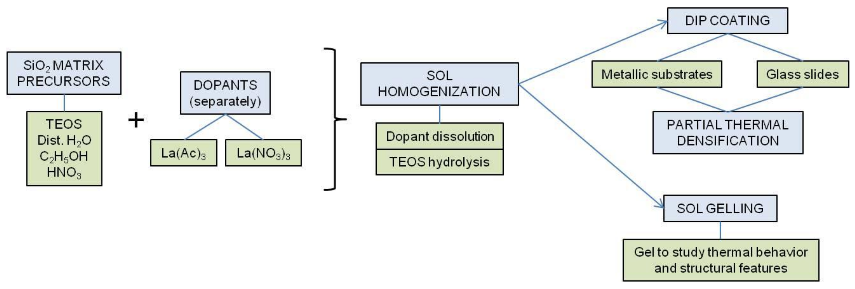
  • Design of environmentally friendly sol-gel coatings doped with corrosion inhibitors: lanthanum salts.
  • Production of these doped sol-gel coatings as a chemically active layer upon copper, bronze, lead and steel substrates.
  • Study of the coatings’ behaviour under laboratory conditions: thermal, structural, chemical and optical.
Two lanthanum salts have been investigated as corrosion inhibitors: lanthanum acetate and lanthanum nitrate. The former is believed to be a compatible compound both with the silica matrix to be formed by hydrolysis and partial polycondensation of silicon tetraethoxide, and with the solvent to be used during the sol preparation (ethanol). The –CH2–CH3 group is present in these three sol components (silica matrix precursor, solvent and dopant), which could improve the gel’s homogeneity in terms of residual organic matter entrapped in the silica network. Moreover, the acetate ions will remain in the gel stage since their thermal decomposition is expected to be at about 450–480 °C (lanthanum oxycarbonate formation) and above 910 °C (lanthanum oxide formation) [27,28]. The latter, lanthanum nitrate, was chosen for its lower release temperature of N O 3 groups (from ~60 °C) with respect to that of –CH2–CH3 groups (~450 °C), which could favour the partial thermal densification of the doped coatings.

2. Materials and Methods

The metal substrates used were copper, bronze, lead and steel slabs from 1.0 to 1.5 mm in thickness and at about 20 mm × 30 mm in size. These metallic substrates were selected on the basis of their frequent presence in cultural heritage items, particularly in museums environments. Table 1, Table 2, Table 3 and Table 4 show, respectively, the results of the chemical analyses carried out for these metallic substrates. Such analyses were undertaken by the respective suppliers.
The sol-gel coatings matrix was obtained from tetraethoxysilane (TEOS) and the active sol-gel dopants were lanthanum acetate and lanthanum nitrate, used separately. Other sol components were absolute ethanol, HNO3 0.01–0.10 M (up to pH ~ 3 in the corresponding sols) and distilled water. All the chemicals used were analytical grade reagents. The scheme of Figure 1 summarizes the synthesis steps.
The sol-gel formulation was calculated to obtain a theoretical mol composition of 1La2O3·99SiO2 (theoretical total densification of the corresponding gel). The sol silica matrix consisted of 1 mol TEOS, 3 mol distilled water, 8 mol absolute ethanol and the necessary volume of HNO3 to get a sol pH ~ 3. The mixture, once stirred and homogenized, yields a pre-hydrolyzed silica sol to which the active La3+-dopant was added (0.02 mol La(CH3COO)3, (La(Ac)3) or 0.02 mol La(NO3)3). After dissolution of the lanthanum salt and further homogenization of the sols, they were ready to be applied as coatings upon the metallic substrates. For comparison purposes, a pure-silica-undoped sol was also prepared to coat the substrates.
The coatings deposition was carried out by dipping, using a home-made device at a constant withdrawal rate of 2 mm s−1, under controlled environmental conditions (25 °C and 35% relative humidity). The partial thermal densification of the coatings was accomplished in a forced air stove at 60 °C for 72 h. Under such conditions the average coatings’ thickness was about 220 ± 15 nm, as estimated by the interference fringe method from the corresponding UV-Vis transmittance spectra of the coated samples [29].
Apart from the coated metallic samples, common glass slides were additionally coated with the same sols to be used in the optical coatings characterization since, for this purpose, transparent and colourless substrates are needed. Moreover, the remaining sols, once all the coatings were applied, were gelled in a forced air stove at 35 °C for 48 h, and then grounded to a fine powder to be used for the structural and thermal characterization of the gels used to obtain the coatings.
The macroscopic aspect of the coatings both on metallic and glass substrates was homogeneous, transparent and colourless.
The UV-Vis transmittance spectra of the coated glass samples were recorded with a Shimadzu 3100 double-beam spectrophotometer (Shimadzu Corporation, Kyoto, Japan) equipped with an integrating sphere. Samples were placed behind a 1 mm width slit mask and the spectra were recorded from 200 to 800 nm with 0.5 nm spectral resolution.
The thermal behaviour of the coatings (grounded gelled materials) was analyzed by differential thermal analysis (DTA) and thermogravimetric analysis (TGA) using a TA Instruments equipment model Q-600 (Waters Corporation, Milford, MA, USA), with a platinum sample holder under air atmosphere and a heating rate of 10 °C min−1 up to 700 °C.
The structural features of the coatings (grounded gelled materials) were investigated by Fourier transformed infrared (FTIR) spectroscopy. The spectra were recorded on the powdered samples diluted in anhydrous KBr (pellets technique) with a spectrometer Perkin Elmer model Spectrum BX (Perkin Elmer Inc., Waltham, MA, USA).
The quality of the coatings was checked with conventional optical microscopy (OM), and petrographic microscopy (PM) observations. The optical microscope was a Motic 168 (Motic Microscopy, Hong Kong, China), and the petrographic one was a Kyowa Bio-Pol 2 polarizing light microscope (Kyowa Electronic Instruments Co. Ltd., Tokyo, Japan). Micrographs were recorded with a Moticam 2500 digital camera.
The chemical resistance of the coatings was tested by accelerated ageing cycles in a climatic chamber Dycometal model CCK-81 following the ISO-9142 standard [30], and in a Kesternich chamber Dycometal model VCK-300 under SO2 atmosphere following the DIN-50018 standard [31]. Additionally, some other resistance tests were carried out: (i) under an organic acids atmosphere (mixture of HCOOH and CH3COOH, since these are the chemicals usually present in the emissions inside museum showcases [32]); and (ii) optical-ultraviolet (UV) irradiation tests carried out for 21 days, at least. Table 5 summarizes the experimental details of the weathering, chemical and optical resistance tests carried out.
The microstructural and textural features of the coatings were observed by field emission scanning electron microscopy (FESEM) with a Hitachi S4800FEM equipment (Hitachi, Tokyo, Japan). Local chemical analyses were undertaken by energy dispersive X-ray spectrometry (EDS) with an Oxford X-Max EDS micro-analyzer attached to the microscope.

3. Results

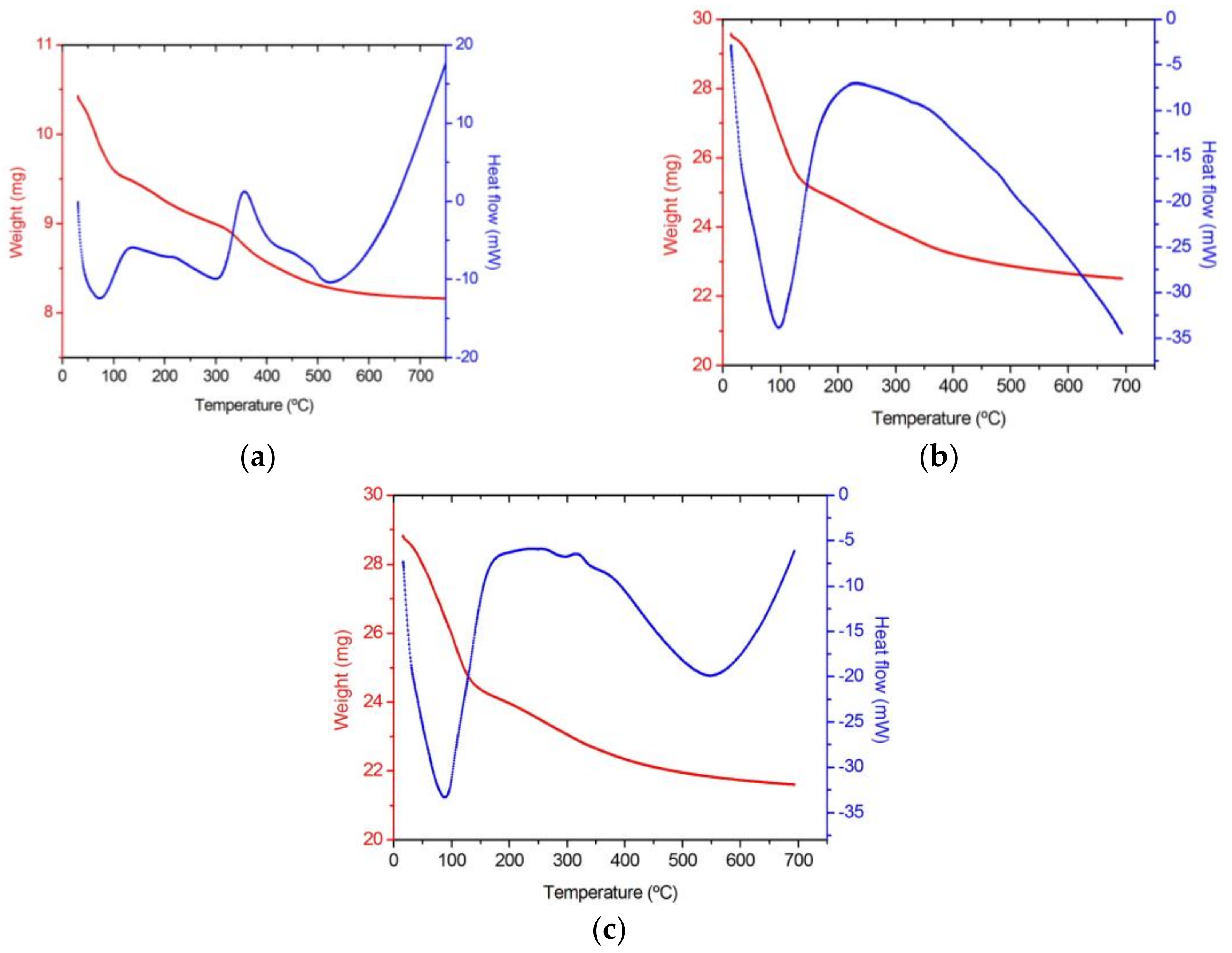
3.1. Thermal Behaviour

Figure 2 shows the DTA-TGA diagrams for the undoped pure-silica gel as well as for the gels doped with lanthanum acetate and lanthanum nitrate.
Table 6 summarizes the assignments of the thermal effects detected and the corresponding weight losses for the same gel samples. The thermal effects in lanthanum-doped gels are similar to those of the pure-silica-undoped gel, but some of them overlap. In addition, the incorporation of both lanthanum dopants delays the loss of adsorbed water and alcohols from the sol and the oxidation of the organic precursors. Therefore, a progressive delay of the thermal evolution of the sol-gel matrix takes place.
TGA diagrams give some additional information on the gels’ behavior (Table 7). At the temperature of partial densification of the coatings (60 °C), the smallest weight loss percentage corresponds to the undoped sample, while in the doped samples it is slightly higher due to the release of adsorbed water additionally associated with the lanthanum salts and perhaps ethanol. The highest weight loss percentage of the La(NO3)3 doped sample could be explained by the early decomposition of nitrate groups at about 60 °C, which cannot be discarded. Regarding the temperatures at which the 5% weight loss takes place, they decrease from the undoped sample to the doped ones, and the sample doped with La(NO3)3 shows the lowest value for the same reason stated above: the beginning of the nitrates’ decomposition. Likewise, the final weight loss percentages at the end of the test (~700 °C) increase from the undoped sample to the La(Ac)3 and to the La(NO3)3 doped samples, which indicates some more intense densification of doped samples. Temperatures and weight loss percentages at which the maximum weight loss rates occur in each sample indicate that both doped samples behave similarly, while the undoped sample losses the lowest weight at the lowest temperature. This could be explained by the early release of water and ethanol in the pure silica sol-gel network not disturbed by dopants.

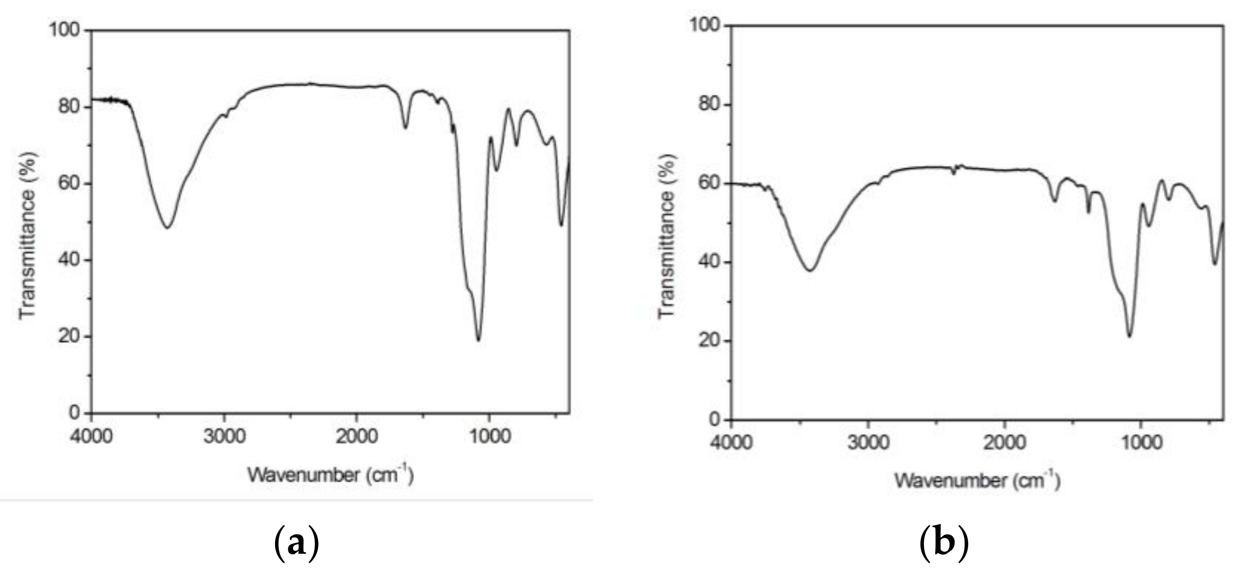
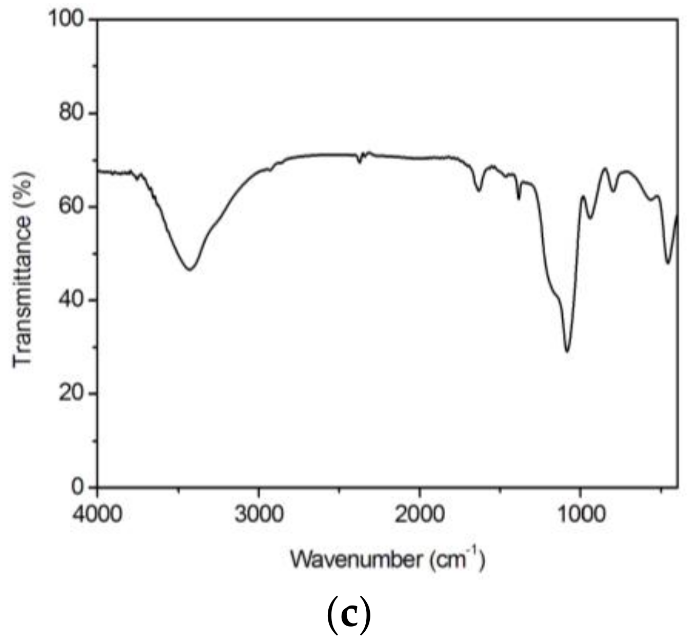
3.2. Structural Features

FTIR spectra of doped and undoped gel samples are shown in Figure 3. The main vibration assignments are summarized in Table 8.
The bands and assignments of the pure-silica-undoped sample are also present or shifted in the lanthanum-acetate-doped sample, which in addition shows other bands due to La(Ac)3. The same occurs for the lanthanum-nitrate-doped sample, which in addition shows other bands due to La(NO3)3. However, no bands due to chemical bonds such as La–O–Si were identified [33,34,35]. This means that La3+-ions are physically entrapped in the pores of the silica sol-gel network and, hence, they remain free enough to react during a common corrosion process.

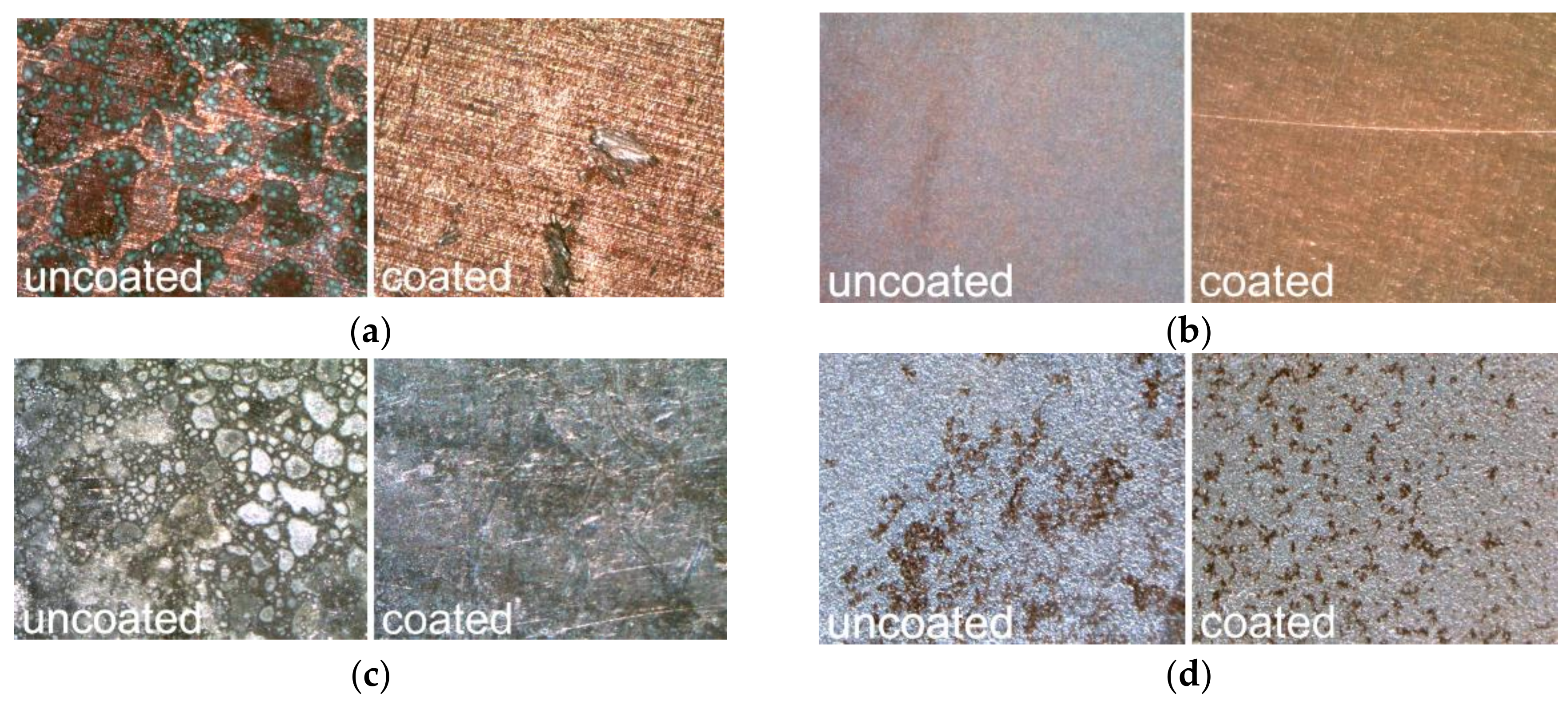
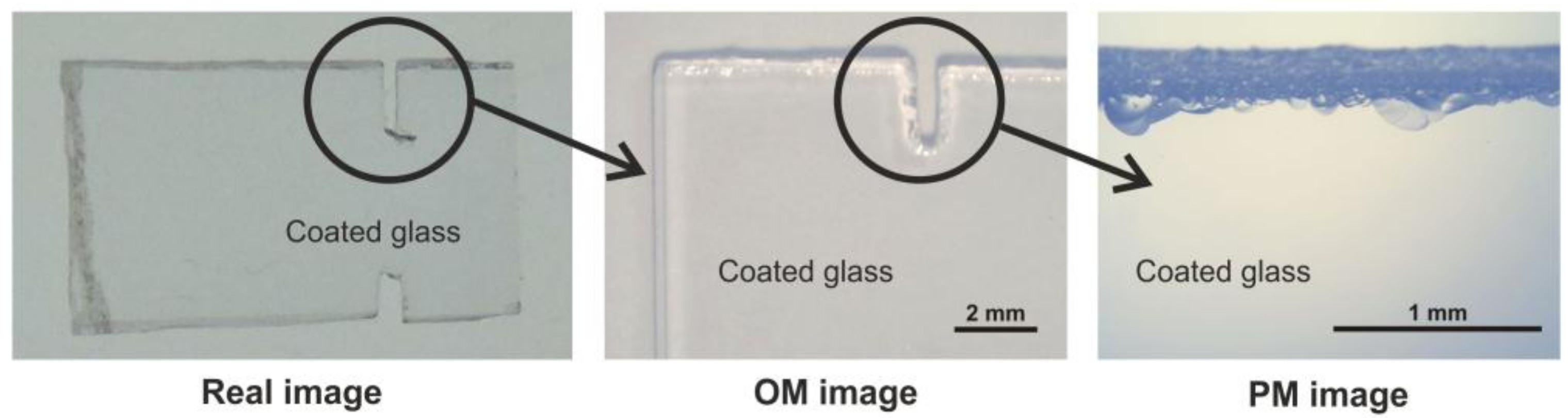
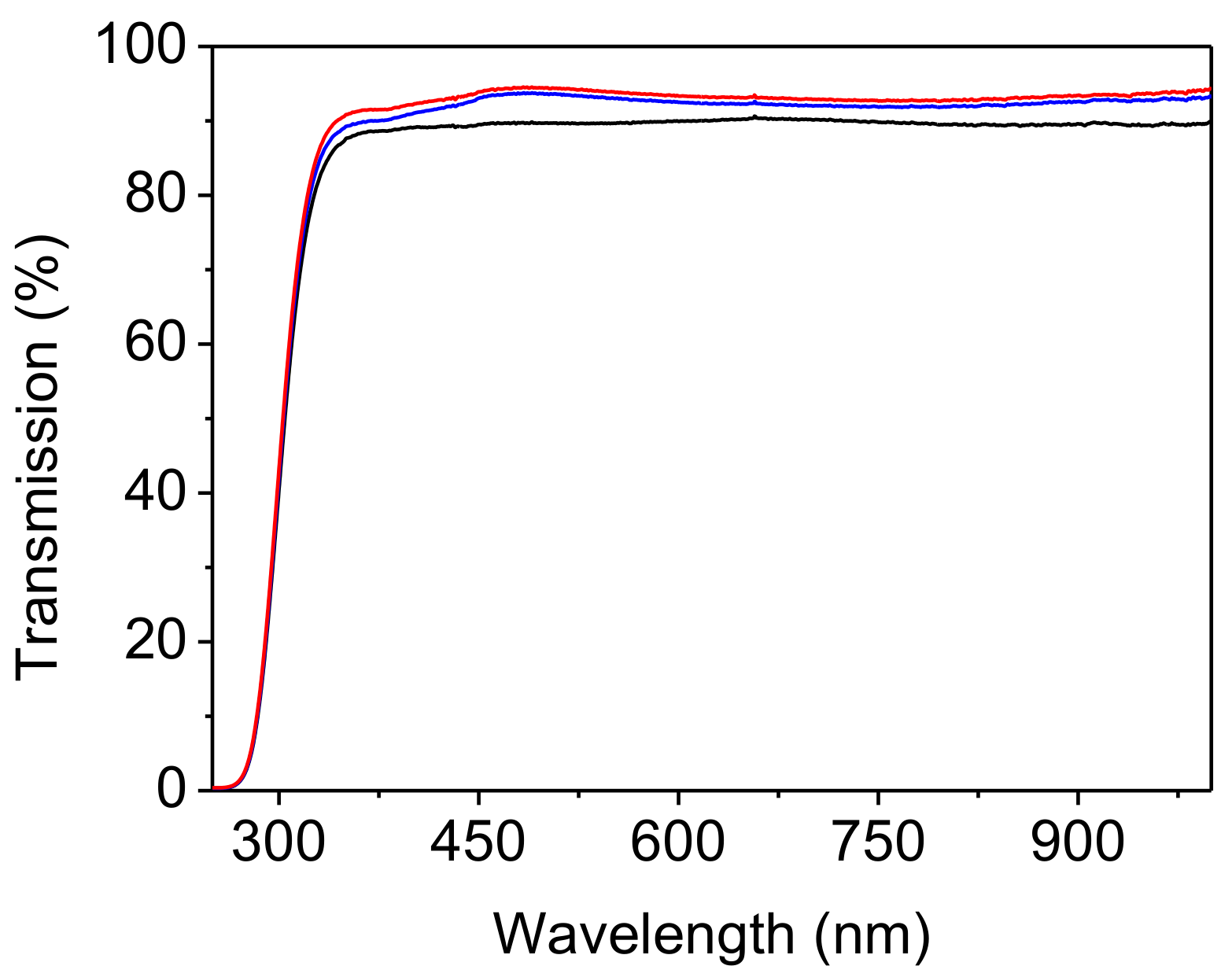
3.3. Macroscopic Quality

After the accelerated ageing treatment in the climatic chamber, all the metallic coated substrates resist well the weathering conditions (up to 55 °C and 85% relative humidity, 21 days). After the treatment in the Kesternich chamber, which simulates a polluted environment (up to 40 °C and 100% relative humidity under SO2 atmosphere), copper, bronze and lead coated samples do not show deterioration or corrosion signs, while small surface pits appeared in coated steel. The same occurs after treatment under a mixture of organic acids (formic and acetic acids), i.e., only the coated steel samples show deterioration signs and the formation of more or less interconnected pits (Figure 4).
PM observations pointed out both the optical quality and the resistance of coatings after the accelerated weathering tests were carried out. For instance, Figure 5 shows the aspect of one of the glass slides coated with La(Ac)3 doped silica after the most aggressive treatment under the Kesternich chamber conditions. Apart from the typical conchoidal fractures due to the glass piece cutting, no signs of alteration can be identified in the PM image, as well as in the corresponding OM image.
All the coated samples were irradiated with UV light for at least 21 days, and after this treatment the coatings’ appearance upon metallic substrates is neutral, colorless and transparent, with the same aspect as before the irradiation, except for the steel substrates in which the coated area appeared slightly yellowish. Nevertheless, no deterioration signs were observed in any kind of samples.
Concerning the optical quality of the coated samples, Vis transmission spectra recorded on glass slides coated with lanthanum-doped silica (Figure 6) show transmission percentages slightly higher than on the uncoated glass slide. This is attributed to the higher refractive index of the uncoated glass slide related to the lanthanum-doped silica coatings. Therefore, the optical quality of lanthanum-doped coatings is optimal to preserve the original appearance of metallic substrates in terms of brightness and reflection.

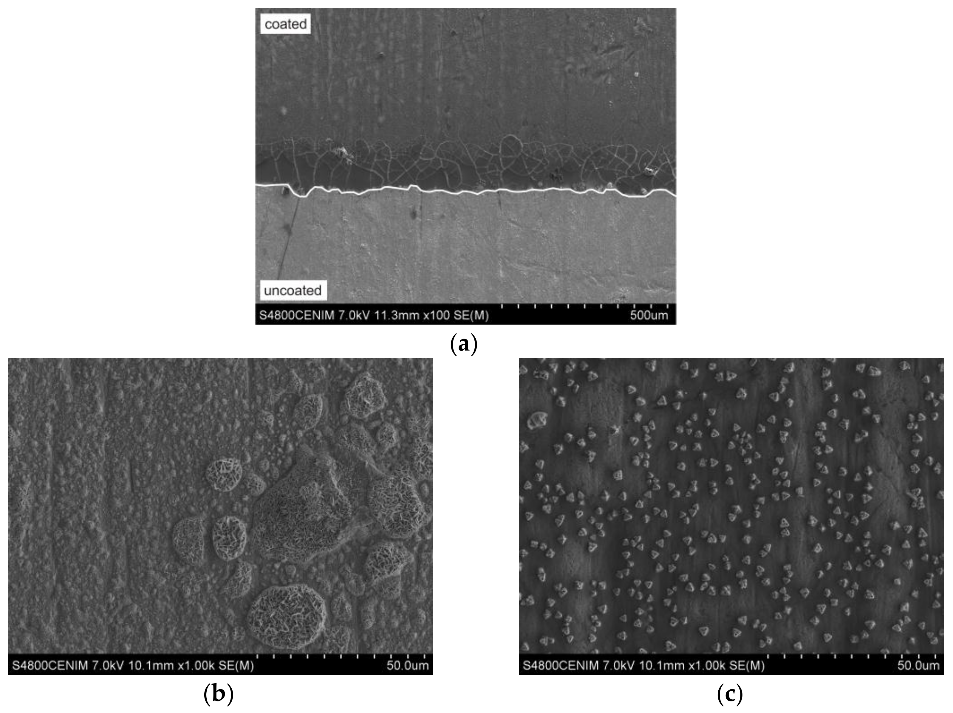
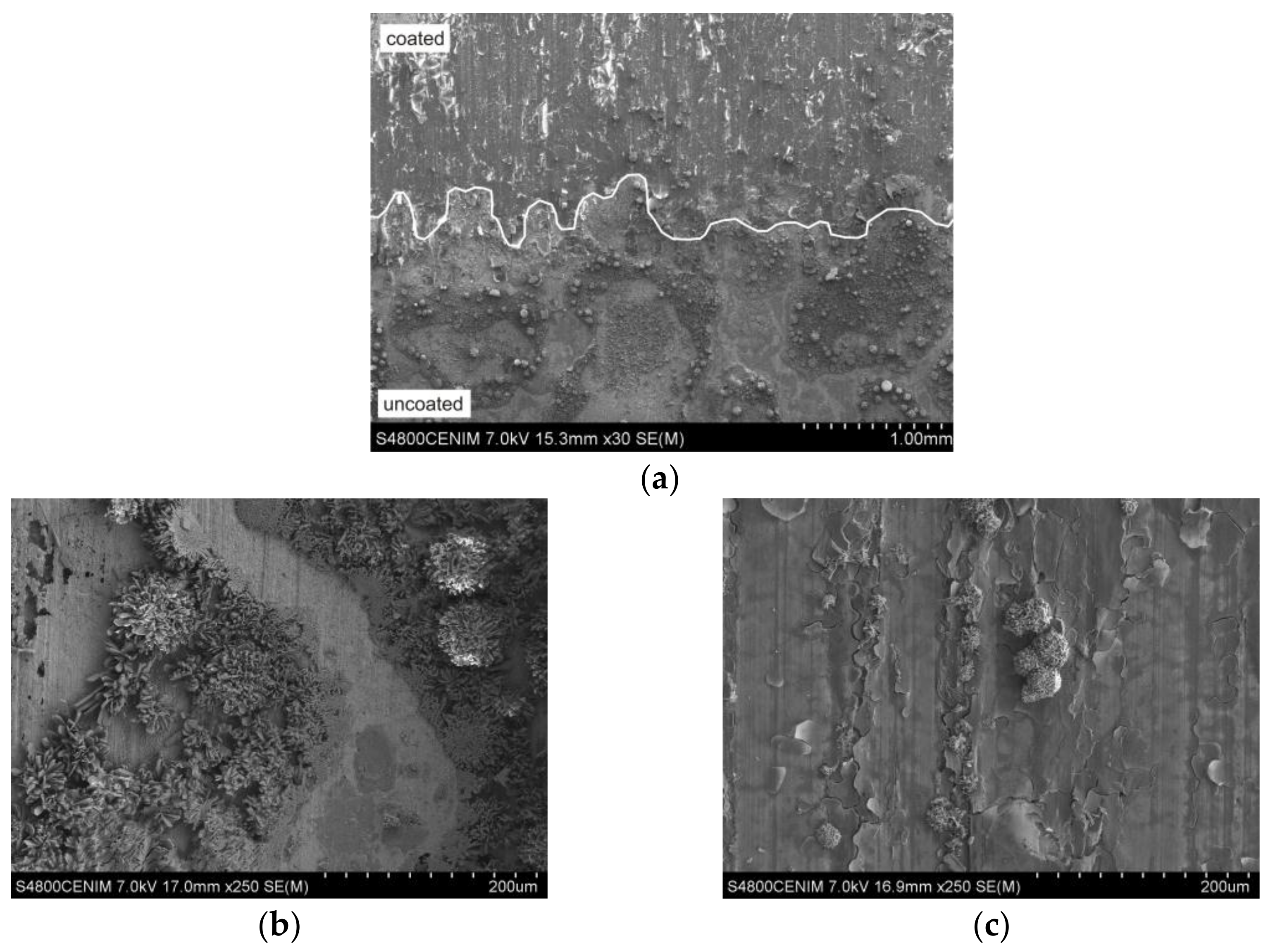
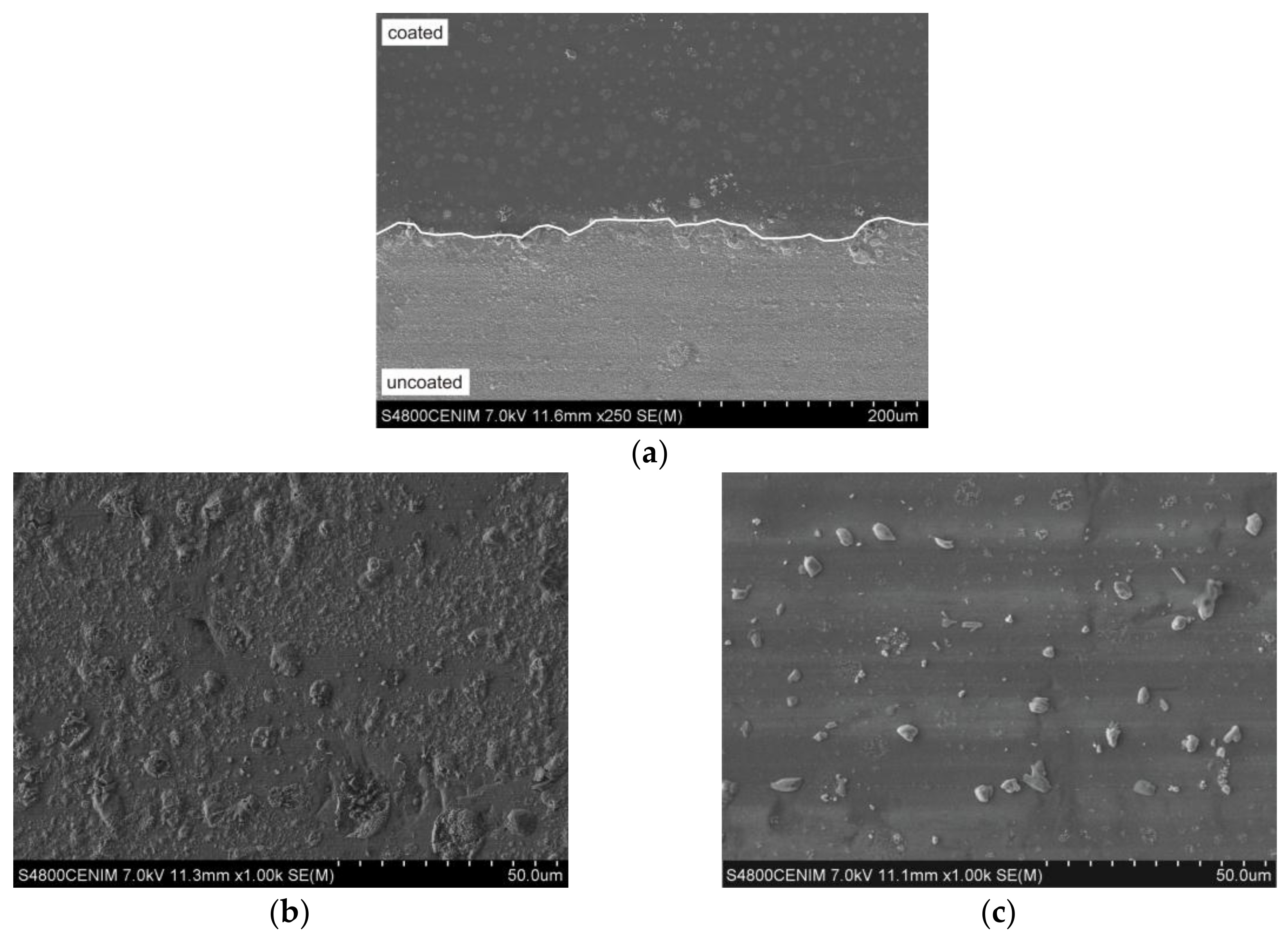
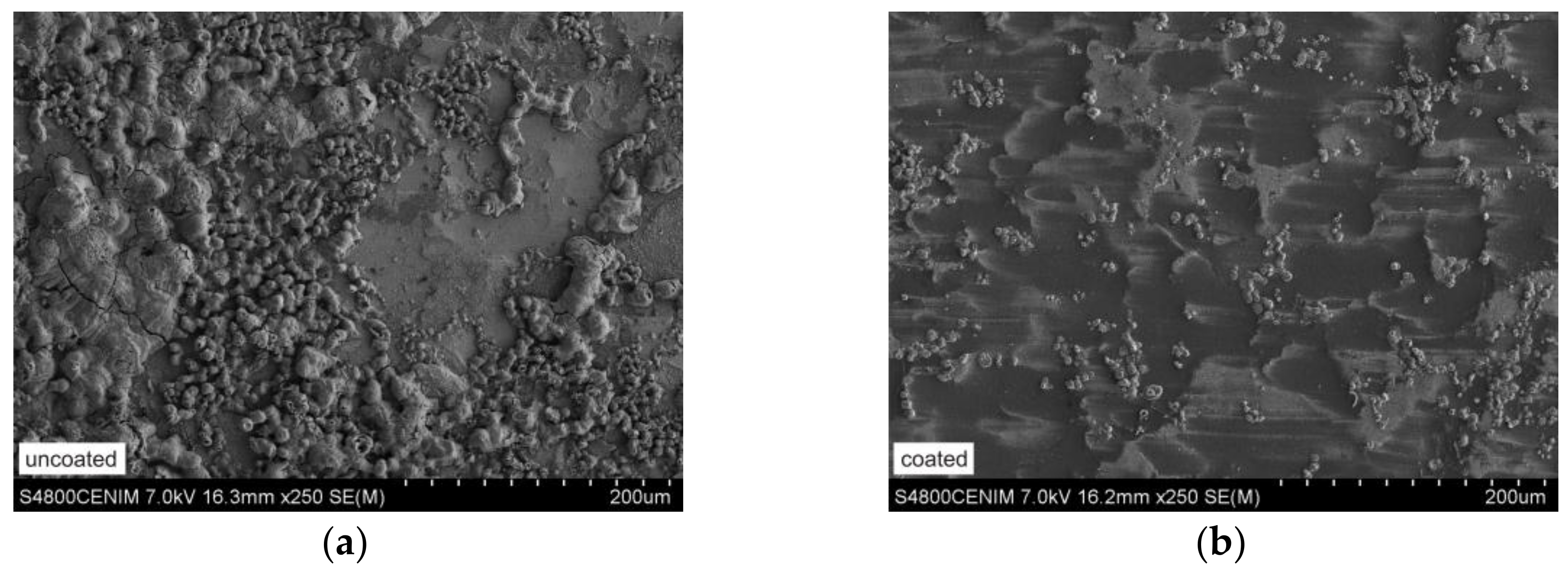
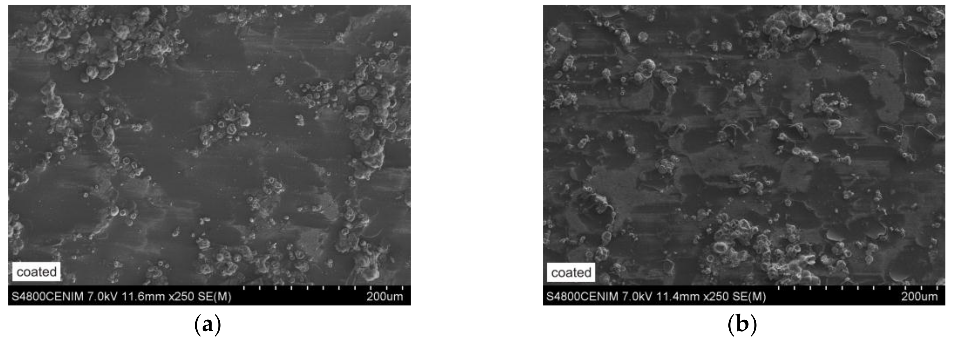
3.4. Microstructural Features

A selection of micrographs corresponding to the results after the most aggressive treatments are shown in this section for each kind of metallic substrate, even though all possible combinations of accelerated weathering tests and metallic substrates coated with the two lanthanum active dopants were carried out and observed by FESEM.
In copper substrates after the treatment in the Kesternich chamber (Figure 7a), the uncoated area shows a heterogeneous surface of corrosion crust with quickly crystallized precipitates (Figure 7b), while in the coated area the sol-gel layer doped with La(NO3)3 appears cracked and a precipitate emerging from the metallic substrate is slowly formed near the cracks (Figure 7c).
Figure 8a shows a FESEM micrograph of a bronze substrate after treatment under organic acids atmosphere. A corrosion crust with abundant precipitates is formed in the uncoated area (Figure 8b). However, the sol-gel layer doped with La(Ac)3 is preserved in the coated area in which the first signs of a precipitate formation can be observed (Figure 8c).
After the organic acids treatment, the lead substrates (Figure 9a) in the uncoated area show a corrosion crust formed by heterogeneous precipitates (Figure 9b). In the corresponding coated area, the sol-gel layer, doped with La(Ac)3, is preserved and a very homogeneous precipitate appears (Figure 9c).
FESEM observations carried out in steel substrates after treatment in the climatic chamber present noticeable differences between the microstructure of coated and uncoated areas. Similar to the former cases, the uncoated area shows a corrosion crust composed of quickly crystallized heterogeneous precipitates (Figure 10a). In the coated area, the coating was deposited upon the lower steel surface (polishing valleys) and the first signs of precipitation upon the higher steel surface can be observed (Figure 10b).
The results obtained after the treatment in the Kesternich chamber revealed that the sol-gel coating fails and a thick corrosion crust was formed. The results were even worse after treatment under organic acids atmosphere: in both doped La(Ac)3 and La(NO3)3 coatings, the sol-gel coating was cracked on the coated area and precipitates appear from the metallic bulk of the sample (Figure 11a,b, respectively).
In this case, the sol-gel coating is cracked and also covers the lower steel surface, while the upper steel surface remains almost uncoated. This is due to the low thickness of the sol-gel layer applied (at about 220 nm). Therefore, a thicker layer would be needed to cover both lower and upper surfaces of the steel substrate.

4. Discussion

As is known, sol-gel silica matrices are partially porous materials even when deposited as thin coatings, as they were prepared here (~220 nm). Such residual porosity is preserved when the thermal densification is carried out at a moderate temperature (60 °C in the present work), and this enhances the reactivity of the sol-gel components, including the active dopants (La3+-ions). In this sense, DTA-TGA results pointed out the additional improvement provided by the incorporation of La3+-ions into the sol-gel silica network, since a progressive delay of the thermal evolution of the sol-gel matrix occurs, which extends the range of the thermal activity of dopants to face the corrosive processes to be produced and then mitigated.
Moreover, La3+-ions are not chemically bonded to the sol-gel silica network, as is demonstrated by the FTIR spectra recorded. This means that they are probably physically entrapped in the porous network and, hence, they are able to react both with external chemicals (e.g., pollutant emissions) and with the metallic substrates. In other words, they are free to behave as an active (reactive) corrosion inhibitor.
As the OM and PM observations and Vis spectrometry demonstrated at the macroscopic scale, the lanthanum-doped coatings provide all physical properties desired, i.e., adequate transparency, achromacity and optimal optical transmission. Thus, they will not change at all the original aspects of the metallic substrates in terms of brightness and reflection. This is an important subject for objects of cultural heritage interest, e.g., museum items, valuable and historical pieces and objects.
The coated (both lanthanum acetate and nitrate) copper substrates resist well the chemical attack of the accelerated treatments carried out in the climatic chamber, under organic acids atmosphere and with UV irradiation. Since the coating remains unaltered, it works as a barrier layer in these cases. However, when coated copper substrates are exposed to an artificial polluted environment (in the Kesternich chamber under SO2 atmosphere), coating breakage occurs and the beginning of a slow precipitation is observed (Figure 7). The emerging precipitate is deposited in the microcracks and seals the surface. Thus, a self-repairing mechanism takes place.
Coated (both lanthanum acetate and nitrate) bronze substrates are resistant to all the treatments tested. Nevertheless, the samples treated under the organic acids atmosphere showed some initial signs of surface precipitation, even though the coating is preserved (no cracks appeared) (Figure 8). This means that in bronze substrates the sol-gel coatings have provided a protective barrier effect.
A similar behavior against the accelerated weathering treatments was observed in coated lead substrates. In these samples the sol-gel coating is preserved and a very homogeneous precipitate appears upon the surface (Figure 9). Once again, a protective barrier effect takes place against corrosion.
Coated steel substrates (both doped with lanthanum acetate and nitrate) are resistant against the climatic chamber treatment and the UV irradiation (protective barrier effect). However, they show macroscopic corrosion signs after the treatments carried out in the Kesternich chamber and under the organic acids atmosphere: the sol-gel coating remains deposited on the lower steel surface due to residual polishing roughness, while the upper surface parts were almost uncoated. This is due to the very low thickness of the sol-gel coating (~220 nm). As a consequence the coating fails and a corrosion crust is formed on the surface (Figure 10). Moreover, in some cases (e.g., lanthanum-nitrate-doped coating after the organic acids treatment) the coating appeared cracked with disperse heterogeneous precipitate not accumulated in the cracks. Thus, neither the protective barrier effect nor the self-repairing mechanism took place.
Taken into account the former issues, the proposed mechanism is as follows. The initial state of the coated metallic substrates exposed to a regular environment (air) is characterized by the presence of Si–O–Si siloxane network, Si–OH terminal silanol groups, La3+-ions in interstitial sites and/or solvated in open pores of the silica matrix. Further, during the accelerated weathering and chemical resistance tests the oxygen reduction
½ O2 + H2O +2 e → 2 OH
takes place as the cathodic reaction, and the metal oxidation occurs
Me0 → Men+ + n e
as the anodic reaction. In this situation, La3+-ions can react and behave as a corrosion inhibitor following, for instance, some precipitation or complexation
La3+ + 3 OH → La(OH)3
The products of such reactions would be the chemical species responsible for the self-repairing mechanism when homogeneous, fine-grain sized particles (precipitate) are deposited near the micro-cracks and thereby sealing them.

5. Conclusions

Concentration of 1 mol % La2O3 with respect to the sol-gel coating formulation has proven to be adequate for La3+-ions to remain entrapped in interstitial sites of the silica matrix, thereby behaving as an active corrosion inhibitor.
The anticorrosive behavior of La3+-ions proceeds by means of a self-repairing mechanism, probably by precipitation of lanthanum oxo-hydroxydes and/or formation of coordination complexes.
Weathering and chemical resistance of lanthanum-doped coatings upon the metallic substrates tested is good enough to ensure a protective role of these sol-gel coatings upon copper, bronze and lead, while steel substrates need thicker coatings.

Acknowledgments

J. Rubio, Ceramic and Glass Institute (CSIC) for thermal analysis and infrared spectra. Project MINEICO/FEDER MAT2015-65445-C2-2-R and program Geomateriales 2 ref. S2013/MIT-2914 (CAM-EU) for financial support. TechnoHeritage Network on Science and Technology for the Conservation of Cultural Heritage for professional support.

Author Contributions

M.-A.V. has been the principal investigator and she has written the manuscript with the collaboration of C.G. and M.G.-H. J.P.-P. and F.A. have carried out the experiments and elaborated the manuscript images. The scientific discussion of results and their interpretation has been done by J.P.-P., F.A., C.G., M.-A.V. and M.G.-H. All the authors have read and approved the final version of the manuscript

Conflicts of Interest

The authors declare no conflict of interest.

References

  1. Chico, B.; de la Fuente, D.; Morcillo, M. Corrosión atmosférica de metales en condiciones climáticas extremas. Bol. Soc. Esp. Ceram. Vidr. 2000, 39, 329–332. (In Spanish) [Google Scholar] [CrossRef]
  2. Black, L.; Allen, G.C. Nature of lead patination. Brit. Corros. J. 1999, 34, 192–197. [Google Scholar] [CrossRef]
  3. Julve, E. Un fenómeno corrosivo deseable: La atractiva pátina verde de los edificios nórdicos y centroeuropeos. An. Quím. 2006, 102, 68–72. (In Spanish) [Google Scholar]
  4. Bethencourt, M.; Botana, F.J.; Calvino, J.J.; Marcos, M.; Rodríguez-Chacón, M.A. Lanthanide compounds as environmentally friendly corrosion inhibitors of aluminum alloys. A review. Corros. Sci. 1998, 40, 1803–1819. [Google Scholar] [CrossRef]
  5. Dumont, B.; Thiery, R.; Welter, J.M.; Duterne, M. Hybrid sol-gel clear coatings for decoration brass profiles. Rev. Met. Paris 2001, 98, 783–788. [Google Scholar] [CrossRef]
  6. Zárraga, R.; Cervantes, J.; Salazar-Hernández, C.; Wheeler, G. Effect of the addition of hydroxyl-terminated polydimethylsiloxane to TEOS-based stone consolidants. J. Cult. Herit. 2010, 11, 138–144. [Google Scholar] [CrossRef]
  7. Barberana-Fernández, A.M.; Carmona-Quiroga, P.M.; Blanco-Varela, M.T. Interaction of TEOS with cementitious materials: Chemical and physical effects. Cem. Concr. Compos. 2015, 55, 145–152. [Google Scholar] [CrossRef]
  8. Mosquera, M.J.; de los Santos, D.M.; Rivas, T. Surfactant-synthesized ormosils with application to stone restoration. Langmuir 2010, 26, 6737–6745. [Google Scholar] [CrossRef] [PubMed]
  9. Franzoni, E.; Graziani, G.; Sassoni, E. TEOS-based treatments for stone consolidation: Acceleration of hydrolysis-condensation reactions by poulticing. J. Sol Gel Sci. Technol. 2015, 74, 398–405. [Google Scholar] [CrossRef]
  10. Mosquera, M.J.; de los Santos, D.M.; Rivas, T.; Sanmartín, P.; Silva, B. New nanomaterials for protecting and consolidating stone. J. Nano Res. 2009, 8, 1–12. [Google Scholar] [CrossRef]
  11. De Bardi, M.; Hutter, H.; Schreiner, M.; Bertoncello, R. Sol–gel silica coating for potash–lime–silica stained glass: Applicability and protective effect. J. Non Cryst. Solids 2014, 390, 45–50. [Google Scholar] [CrossRef]
  12. Dal Bianco, B.; Bertoncello, R. Sol–gel silica coatings for the protection of cultural heritage glass. Nucl. Instrum. Met. Phys. Res. B 2008, 266, 2358–2362. [Google Scholar] [CrossRef]
  13. Constâncio, C.; Franco, L.; Russo, S.; Ajinho, C.; Pires, J.; Vaz, M.F.; Carvalho, A.P. Studies on polymeric conservation treatments of ceramic tiles with Paraloid B-72 and two alkoxysilanes. J. Appl. Polym. Sci. 2010, 116, 2833–2839. [Google Scholar] [CrossRef]
  14. Zucchi, F. Sol-gel coatings for the preservation of metallic heritage artefacts. In Corrosion and Conservation of Cultural Heritage Metallic Artefacts, 1st ed.; Dillmann, P., Watkinson, D., Angelini, E., Adriaens, A., Eds.; European Federation of Corrosion (EFC) Series; Woodhead Publishing Limited: Oxford, UK, 2013; pp. 540–551. ISBN 9781782421542. [Google Scholar]
  15. Figueira, R.B.; Fontinha, I.R.; Silva, C.J.R.; Pereira, E.V. Hybrid sol-gel coatings: Smart and green materials for corrosion mitigation. Coatings 2016, 6, 12. [Google Scholar] [CrossRef]
  16. Figueira, R.B.; Silva, C.J.R.; Pereira, E.V. Organic–inorganic hybrid sol–gel coatings for metal corrosion protection: A review of recent progress. J. Coat. Technol. Res. 2014, 12, 1–35. [Google Scholar] [CrossRef]
  17. Wang, D.; Bierwagen, G.P. Sol–gel coatings on metals for corrosion protection. Prog. Org. Coat. 2009, 64, 327–338. [Google Scholar] [CrossRef]
  18. Arenas, M.A.; Bethencourt, M.; Botana, F.J.; de Damborenea, J.; Marcos, M. Inhibition of 5083 aluminum alloy and galvanised steel by lanthanide salts. Corros. Sci. 2001, 43, 157–170. [Google Scholar] [CrossRef]
  19. García-Heras, M.; Jiménez-Morales, A.; Casal, B.; Galván, J.C.; Radzki, S.; Villegas, M.A. Preparation and electrochemical study of cerium-silica sol-gel thin films. J. Alloys Compd. 2004, 380, 219–224. [Google Scholar] [CrossRef]
  20. Montemor, M.F.; Ferreira, M.G.S. Corrosion performance of a two-step pre-treatment for galvanized steel based on lanthanum nitrate and silanes. Surf. Interface Anal. 2004, 36, 773–776. [Google Scholar] [CrossRef]
  21. Xiaoxiao, W.; Gang, K.; Ziwen, S.; Chunshan, C. Preparation and corrosion performance of lanthanum nitrate conversion coating on hot-dip Galfan steel. Chin. J. Mater. Res. 2016, 30, 269–276. [Google Scholar] [CrossRef]
  22. Yasakau, K.A.; Zheludkevich, M.L.; Ferreira, M.G.S. Lanthanide salts as corrosion inhibitors for AA5083. Mechanism and efficiency of corrosion inhibition. J. Electrochem. Soc. 2008, 155, C169–C177. [Google Scholar] [CrossRef]
  23. Bethencourt, M.; Botana, F.J.; Cauqui, M.A.; Marcos, M.; Rodríguez, M.A.; Rodríguez-Izquierdo, J.M. Protection against corrosion in marine environments of AA5083 Al-Mg alloy by lanthanide chlorides. J. Alloys Compd. 1997, 250, 455–460. [Google Scholar] [CrossRef]
  24. Abuín, M.; Serrano, A.; Llopis, J.; García, M.A.; Carmona, N. Silica doped with lanthanum sol–gel thin films for corrosion protection. Thin Solid Films 2012, 520, 5267–5271. [Google Scholar] [CrossRef]
  25. Fan, H.; Li, S.; Shi, Z.; LV, X.; Zhao, Z. Studies of the conversion coatings formed by combined use of lanthanum salt and benzotriazole on commercial brass. Anti Corros. Method. Mater. 2012, 59, 32–38. [Google Scholar] [CrossRef]
  26. Gang, K.; Lingyan, L.; Jintang, L.; Chunshan, C.; Zheng, Z. Study on lanthanum salt conversion coating modified with citric acid on hot dip galvanized steel. J. Rare Earth 2010, 28, 461–465. [Google Scholar] [CrossRef]
  27. Patil, K.C.; Chandrashekhar, G.V.; George, M.V.; Rao, C.N.R. Infrared spectra and thermal decompositions of metal acetates and dicarboxylates. Can. J. Chem. 1968, 46, 257–265. [Google Scholar] [CrossRef]
  28. Edwards, D.A.; Hayward, R.N. Transition metal acetates. Can. J. Chem. 1968, 46, 3443–3446. [Google Scholar] [CrossRef]
  29. García, M.A.; Paje, S.; Llopis, J.; Villegas, M.A. Influencia de las condiciones de preparación en la luminiscencia de recubrimientos de sílice pura. Bol. Soc. Esp. Ceram. Vidr. 2000, 39, 641–646. (In Spanish) [Google Scholar] [CrossRef]
  30. ISO-9142 Guía Para la Selección de Condiciones de Envejecimiento Normalizadas de Laboratorio Para Someter a Ensayo Juntas Pegadas; AENOR: Madrid, Spain, 2004. (In Spanish)
  31. DIN-50018 Sulfur Dioxide Corrosion Testing in a Saturated Atmosphere; DIN Deutsches Institut für Normung e.V.: Berlin, Germany, 1997.
  32. Tétreault, J.; Cano, E.; van Bommel, M.; Scott, D.; Dennis, M.; Barthés-Labrousse, M.G.; Minel, L.; Robbiola, L. Corrosion of copper and lead by formaldehyde, formic acid and acetic acid vapours. Stud. Conserv. 2003, 48, 237–250. [Google Scholar] [CrossRef]
  33. Krol, D.M.; Smets, B.M.J. Group III ions in sodium silicate glass, 2, Raman study. Phys. Chem. Glasses 1984, 25, 119–125. [Google Scholar]
  34. Smets, B.M.J.; Krol, D.M. Group III ions in sodium silicate glass, 1, X-ray photoelectron study. Phys. Chem. Glasses 1984, 25, 113–118. [Google Scholar]
  35. Ellison, A.J.G.; Hess, P.C. Vibrational spectra of high-silica glasses of the system K2O-SiO2-La2O3. J. Non Cryst. Solids 1991, 127, 247–258. [Google Scholar] [CrossRef]
  36. Rizzo da Rocha, S.M.; da Silva Queiroz, C.A.; Abrao, A. Synthesis and characterization of lanthanum acetate for application as a catalyst. J. Alloys Compd. 2002, 344, 389–393. [Google Scholar] [CrossRef]
  37. Bünzli, J.C.G.; Moret, E.; Yersin, J.R. Vibrational spectra of anhydrous lanthanum, europium, gadolinium, and dysprosium nitrates and oxinitrates. Helv. Chim. Acta 1978, 61, 762–771. [Google Scholar] [CrossRef]
  38. Klingenberg, B.; Vannice, M.A. Influence of pretreatment on lanthanum nitrate, carbonate, and oxide powders. Chem. Mater. 1996, 8, 2755–2768. [Google Scholar] [CrossRef]
Figure 1. Scheme of the synthesis steps for obtaining sol-gel coatings and bulk gels.
Coatings 08 00138 g001
Figure 2. DTA and TGA diagrams of some of the samples studied. (a) Pure SiO2 gel; (b) La(Ac)3 doped gel; (c) La(NO3)3 doped gel.
Coatings 08 00138 g002
Figure 3. FTIR spectra of some of the samples studied. (a) Pure SiO2 gel; (b) La(Ac)3 doped gel; (c) La(NO3)3 doped gel.
Coatings 08 00138 g003aCoatings 08 00138 g003b
Figure 4. MO images of uncoated and coated areas of some of the samples studied after the weathering tests indicated. (a) Copper, x14, La(NO3)3 doped coating, Kesternich Chamber; (b) Bronze, x14, La(Ac)3 doped coating, organic acids treatment; (c) Lead, x14, La(NO3)3 doped coating, Kesternich Chamber; (d) Steel, x7, La(NO3)3 doped coating, organic acids treatment.
Coatings 08 00138 g004
Figure 5. Photograph, OM image and PM image of a glass slide piece coated with La(Ac)3 doped silica after the treatment in the Kesternich chamber.
Coatings 08 00138 g005
Figure 6. Visible spectra of some of the samples studied. Black line: uncoated common glass slide. Blue line: glass slide coated with La(Ac)3 doped silica. Red line: glass slide coated with La(NO3)3 doped silica.
Coatings 08 00138 g006
Figure 7. (a) FESEM image of a copper substrate in the coated/uncoated interface (La(NO3)3 doped coating) after the weathering test in the Kesternich Chamber; (b) Detail of the uncoated area; (c) Detail of the coated area.
Coatings 08 00138 g007
Figure 8. (a) FESEM image of a bronze substrate in the coated/uncoated interface (La(Ac)3 doped coating) after the weathering test under organic acids atmosphere; (b) Detail of the uncoated area; (c) Detail of the coated area.
Coatings 08 00138 g008
Figure 9. (a) FESEM image of a lead substrate in the coated/uncoated interface (La(Ac)3 doped coating) after the weathering test under organic acids atmosphere; (b) Detail of the uncoated area; (c) Detail of the coated area.
Coatings 08 00138 g009
Figure 10. FESEM image of a steel substrate after the weathering test in the climatic chamber: (a) Uncoated area; (b) Coated area (La(Ac)3 doped coating).
Coatings 08 00138 g010
Figure 11. FESEM image of a steel substrate after the weathering test under organic acids atmosphere: (a) Coated area (La(Ac)3 doped coating); (b) Coated area (La(NO3)3 doped coating).
Coatings 08 00138 g011
Table 1. Chemical composition of the copper substrates.
SubstratesChemical Composition (wt %)
CopperCuOthers
99.95rest
Table 2. Chemical composition of the bronze substrates.
SubstratesChemical Composition (wt %) (min–max)
BronzeCuSnPbZnNiOthers
rest6–85–83.5–5.50–20–1
Table 3. Chemical composition of the lead substrates.
SubstratesChemical Composition (wt %)
LeadCuSnZnFeSbBiAsAgCdPb
0.03190.00040.00030.00070.00050.02330.00020.00160.0009rest
Table 4. Chemical composition of the steel substrates.
SubstratesChemical Composition (wt %)
SteelFeCMnPSSiAl
rest0.0520.2460.0190.0240.0070.051
Table 5. Experimental details of the weathering and chemical treatments carried out.
TreatmentTest EquipmentConditionsTime
Accelerated ageingClimatic chamberStandard ISO-9142
23 °C 85% RH 1 day
55 °C 28% RH 1 day
23 °C 85% RH 3 days
55 °C 28% RH 2 days
21 days
Accelerated ageing under SO2 atmosphereKesternich corrosion chamberStandard DIN 50018
40 °C 100% RH
0.5 L SO2 8 h closed door
16 h open door
1 cycle
Organic acidsDesiccatorAcetic acid + formic acid (0.01 vol. %) saturated atmosphere7 days
UV irradiationUV lamp300 W21 days
Table 6. DTA and TGA assignments of some of the samples studied.
Gel SampleDTATGA
T (°C)EffectT (°C)Effect
100 SiO2
Blank
73ENDO Loss adsorbed water and alcoholsRoom-100Great loss of water and alcohols
130–220EXO Organic precursors oxidation100–300Great loss due to organic matter release
356EXO Organic groups decomposition300–400
522ENDO Si-OH groups release500–600Small loss of chemically bonded water
1La2O3·99SiO2
La(Ac)3
97ENDO Loss adsorbed water and alcoholsRoom-135Great loss of water and alcohols
130–275EXO Organic precursors oxidation130–400Great loss due to organic matter release
350EXO Organic groups decomposition
500–ENDO Si-OH groups release500–Progressive loss of chemically bonded water
1La2O3·99SiO2
La(NO3)3
87ENDO Loss adsorbed water and alcoholsRoom-140Great loss of water and alcohols
140–295EXO Organic precursors oxidation140–400Great loss due to organic matter release
300–400EXO Organic groups decomposition
545ENDO Si-OH groups release500–Progressive loss of chemically bonded water
Table 7. Additional data concerning TGAs of some of the samples studied.
Dopant in the CoatingWeight Loss at 60 °C (%)Temperature at Which 5% Weight Loss Occurs (°C)Final Weight Loss at 700 °C (%)Temperature at Which Maximum Weight Loss Rate Occurs (°C)Weight Loss at the Maximum Weight Loss Rate (%)
None (blank)3.3671.6721.5965.174.03
La(Ac)33.5570.2623.8894.919.03
La(NO3)34.0667.1025.0589.948.47
Table 8. FTIR assignments of some of the samples studied [36,37,38].
Gel SampleWavenumber (cm−1)AssignmentIntensity 1Observations
100 SiO2
Blank
465δ Si–O–SiXXXXSiloxane matrix
577; 801νs Si–O–SiXXX; XXXSiloxane matrix
951ν Si–OHXXXRaw alkoxides
1085ν Si–O; vas Si–OXXXXXSi–OCH3; Si–O–Si
1166νs C–OXXXXX, xRaw alkoxides
1286νas C–OXX, xRaw alkoxides
1398; 1450δ CH2X; XSi–R
1637ν C=CXXXRaw alkoxides
2921; 2988ν C–H; ν C–HX; XSi–R; –OCH2CH3
3430ν O–HXXXXXSi–OH
1La2O3·99SiO2
La(Ac)3
463δ Si–O–Si ; π COO–XXXSiloxane matrix; La(Ac)3
564ν La–OXXXLa(Ac)3
800νs Si–O–SiXXXSiloxane matrix
948ν Si–OH; ν C–CXXXRaw alkoxides; La(Ac)3
1083ν Si–O; vas Si–O; ν CH3XXXXXSi–OCH3; Si–O–Si; La(Ac)3
1154νs C–OXXXXX, xRaw alkoxides
1384δs CH3XXXLa(Ac)3
1460δas CH3XLa(Ac)3
1632ν C=CXXXRaw alkoxides
2854; 2925νs C–H; ν C–HXLa(Ac)3; Si–R
3433ν O–HXXXXXSi–OH
1La2O3·99SiO2
La(NO3)3
457δ Si–O–SiXXXXSiloxane matrix
565ν La–OXXXLaO(NO3)
798ν NO3XXXLa(NO3)3
944ν Si–OHXXXRaw alkoxides
1084ν Si–O; vas Si–OXXXXXSi–OCH3; Si–O–Si
1160νs C–OXXXXX, xRaw alkoxides
1387; 1463δ CH2X; XSi–R
1632ν C=CXXXRaw alkoxides
2850; 2925νs C–HXSi–R
3429ν O–HXXXXXSi–OH
Note: 1 XXXXX very intense; XXXX intense; XXX medium; XX low; X very low; x shoulder.

