1. Introduction
Coatings which are immersed or permanently in contact with water will inevitably accumulate organisms on their surface, i.e., bio-fouling will take place. This phenomenon is of major relevance in many application fields. In marine coatings, for example, the accumulation of fouling leads to an increased drag resistance and higher fuel consumption [
1]. Furthermore, it requires frequent maintenance and dry-dock repair which have a highly negative environmental and economic impact [
2]. A second example is in the medical field, where coatings are applied on medical devices, such as catheters and contact lenses to provide a certain lubricious property. Accumulation of foulants such as blood cells, components from body fluids or even bacteria and viruses would increase the friction resulting in wounds due to the rupture of cells and also induce infections [
3,
4]. However, another very relevant example is in membranes for water purification, where the filtration process and the quality of water is highly affected by surface fouling, including inorganic scaling/deposition, colloidal fouling, organic fouling and biofouling in general [
5].
Several anti-fouling (AF) strategies have been reported for polymer coatings in which the characteristics of the top surface, i.e., chemical composition and topography, are critical for the effectiveness and long time performance of this surface functionality, as discussed in several literature reviews available [
6,
7,
8,
9,
10]. More recently, hydrophilic high surface energy coatings emerged as an interesting option to prevent the adhesion of foulants, most of them making use of the well-known anti-fouling character of polyethylene glycol (PEG)-based derivatives [
11,
12,
13,
14,
15]. Although the working principle of this type of coating is still unclear and several mechanisms have been proposed by different authors [
9,
16,
17], it is widely assumed that the use of hydrophilic polymeric surfaces allows the formation of a hydration layer by means of hydrogen bonding between the water molecules and the hydrophilic polymer, which reduces the probability of proteins to adhere to the surface, thus reducing the initial attachment and subsequent accumulation of foulants. However, once the coating is damaged and the surface characteristics (in this case the hydrophilicity) are lost upon wear, degradation or attachment of the first biorganisms, the AF properties are no longer effective and the wet surfaces will become rapidly fouled. Introducing a self-repairing mechanism, which can intrinsically replenish the damaged surface with new hydrophilic AF chemical moieties, would allow a high AF performance level throughout the life-time of the coatings, with major economic and environmental benefits.
As previously demonstrated for analogous hydrophobic coatings [
18,
19,
20], an intrinsic and spontaneous self-replenishing mechanism can be incorporated in coatings by fulfilling some design requirements. The coating should contain: (i) a reservoir of hydrophilic dangling chains chemically bonded to the bulk network; (ii) these dangling chains should be sufficiently mobile, e.g., typically governed by a low
Tg of the polymer components, to reorient upon creation of new interfaces; and (iii) a proper hydrophilic–hydrophobic balance between all the coating components (i.e., dangling chains and network polymer precursors), which will provide the driving force for the reorientation of the dangling chains towards the air–coating, or in this case, water–coating, interface once damage occurs.
To date, most of the self-replenishing systems found in literature are hydrophobic, while the development of self-healing hydrophilic coatings is still scarcely addressed [
21,
22,
23,
24]. In one of the few examples, Minko et al. settled guidelines towards the design of materials with long-lasting hydrophilicity and anti-fouling properties. The hydrophilicity and AF properties of PEG 2D surface-grafted and 3D-network grafted films, possessing PEG chains in the surface and inside the network film, were studied and compared. For the measuring time of four weeks used, the 3D-grafting structures demonstrated much higher hydrophilicity stability and fouling resistant properties than the 2D films due to the spontaneous rearrangement of the chains stored inside the film [
23]. In a more recent publication self-assembled microgel spheres with grafted hydrophilic chains were synthesized. The films presented oil-repellent and AF properties, and were able to self-repair after induced damage. Also in this case, the self-healing function was attributed to the 3D structure combined with the presence of a reservoir of hydrophilic chains [
24].
It should also be noted that, while for some specific applications an easily degradable polymer coating may be required (e.g., for short-term medical implants), for many others, the overall long term stability of the hydrophilic self-healing coatings when immersed in water and the absence of leachable materials (i.e., resulting from bulk or network degradation) are essential, e.g., in the marine field and especially on medical devices in contact with the human skin or body-fluids.
Due to their interesting thermal and mechanical properties, aliphatic Poly(carbonates) (PCs) find applications in a wide variety of fields, such as in regenerative medicine, drug delivery and in the coatings industry [
25,
26,
27,
28]. Furthermore, PCs typically present longer hydrolytic stability in water when compared to polyesters, are highly transparent to visible light and have a tunable and generally low
Tg value [
29,
30,
31]. Although this low
Tg can be envisaged as a major drawback for some applications, they are advantageous for preparing protective and functional coatings which are required to interact favorably with water. This type of polymer can confer long-time water stability and high transparency to the coatings while immersed in water, and also the proper mobility in the system for self-replenishing. Additionally, PCs can be easily prepared by Cationic Ring Opening Polymerization (CROP) via green approaches using organic acids (e.g., trifluoromethanesulfonic acid, TFA) as catalysts, resulting in metal-free polymers which are very attractive for medical and marine coatings in general.
The current study focuses on developing hydrophilic self-replenishing coatings, targeting application areas such as marine or medical AF coatings. To this purpose we designed three component polyurethane-based networks, with a mixture of tri-branched and linear poly(1,3-propylene)carbonates (PC) as polymeric matrix, a triisocyanate (tHDI) as crosslinker and PEG moieties as hydrophilic dangling chains, which preferentially orient towards the water-coating interfaces providing AF properties.
The preparation of the AF hydrophilic networks and their characterization by FTIR, DSC, static and dynamic contact angle and water uptake measurements is presented. The long-term stability and appearance of the coatings in water is addressed and the anti-fouling potential is discussed, based on preliminary protein adsorption measurements.
The design of the coatings was directed to provide self-replenishing characteristics, i.e., to recover the surface hydrophilicity and related functionalities. The recoverability of the surface properties in water is demonstrated by dynamic contact angle measurements, before and after, controlled damage which was intentionally induced at the coatings surface.
2. Experimental
2.1. Materials
Firstly, 1,3-propanediol, ethyl chloroformate, triethylamine (TEA), trifluoroacetic acid (TFA, 99% for HPLC), pyridine, poly(ethylene glycol) methyl ether with average Mn of 550 and 2000 g·mol−1 (mPEG550 and mPEG2000, respectively), and Fibrinogen (FB, ~340 kDa) were purchased from Sigma-Aldrich (St. Louis, MO, USA) Poly(ethylene glycol) methyl ether average Mn 1000 g·mol−1 (mPEG1000) was purchased from TCI Chemicals (Tokyo, Japan). A polyisocyanate crosslinker, Desmodur N3600 containing primarily a trimer of hexamethylenediisocianate (further noted as tHDI, hydroxyl group functionality 2.8) was kindly supplied by Perstorp (Malmö, Sweden). Aluminium oxide 90 active neutral (activity stage I) used for column chromatography was purchased from Merck (Kenilworth, NJ, USA). The Phosphate Buffer Saline (PBS) solution 1X with pH 7.4 was purchased from Thermo Fischer Scientific (Waltham, MA, USA). Organic solvents were purchased from Biosolve (Dieuze, France). Trimethylolpropane (TMP) was purchased from Merck and dried at 45 °C during 3 h before use. All the other chemicals were used as received.
2.2. Characterization Techniques and Procedures
Thermogravimetric Analysis (TGA) and Differential Scanning Calorimetry (DSC). The thermal properties of the coatings (5–10 mg samples) were studied on a TGA-TA Q500 equipment (from TA Instruments, New Castle, DE, USA), heating from 25 to 600 °C at 10 °C/min under a nitrogen flow. DSC measurements were performed on a DSC-TA Q100 (from TA Instruments). Samples (6–8 mg) were measured with a heating–cooling–heating cycle that runs from −80 °C to 80 °C at 10 °C/min under a nitrogen flow. The second heating run was selected for the analyses of the results. The coating thicknesses were measured on a Veeco Dektak 150 profilometer (from Veeco, Plainview, NY, USA).
Extractables. The amount of non-reacted or non-network incorporated species was extracted from coatings by immersing a known amount of coating detached from the substrate (typically 50–100 mg) in water and acetone. After 24 h immersion the coatings were dried overnight in vacuum at 45 °C. The weight loss (%) was calculated from the mass of coating after extraction divided by the mass coating before extraction ×100. Each coating was measured in triplicate. Water and acetone liquid extracts were evaporated at room temperature and afterwards vacuum dried at 45 °C overnight to recover and analyze the extracted solid residues by 1H-NMR.
Contact Angle. Static and dynamic contact angle measurements were performed on a OCA30 contact angle system (from DataPhysics, Regensburg, Germany) by using distilled water as a probe liquid. For static measurements water droplets of 8 µL were deposited on the surface. For dynamic measurements the advancing water contact angle (CAAdv) was measured with the ARCA software tool in the following way: a 2 µL droplet was first placed on the surface. Water was then injected into the droplet up to 8 µL at 0.5 µL/s. After a waiting period of 2 s water was retracted from the droplet by using the same settings as for the water injection. Each coating was measured in triplicate. All measurements were done in coatings previously soaked in water to minimize the water absorption effect.
Water uptake. The water uptake (%) was calculated from the following equation: Wt − W0/W0 × 100, where Wt is the weight of the swollen coating at a specific time and W0 the initial weight of the dry coating. Each coating was measured in triplicate. Typically, ~50–100 mg of the free standing film coatings were immersed in demineralized water. The amount of absorbed water was measured gravimetrically at several immersion times. The water absorption experiments allowed to determine the percentage of water uptake after 24 h as well as the degradation of the coatings which was evaluated over one year.
Coating damage. Controlled damage was induced on dry coatings by using a setup previously described for self-replenishing studies on hydrophobic coatings [
19]. A piece of 1200/4000 grit silicon carbide sand paper (2 × 2.4 cm
2) was glued to a metal disk which was loaded with additional metal rings with a final mass of 30.9 g, resulting in a constant pressure on the abrasion area of about 4300 Pa. To perform the abrasion test, the sandpaper (with the metal disks on top of it) was applied on the coatings surface and moved manually along the parallel direction (back and forth). The extent of damage was detected by measuring the thickness (Dektak 150 profilometer, from Veeko) and the surface wettability (CA
Adv) before and after damage. The sand paper was replaced every 50 cycles to avoid transfer of debris and contamination. The surface hydrophilicity recovery was quantified by calculating the Self-Replenishing Efficiency (SRE), where CA
initial is the water CA of the coatings before damage and CA
final is the water CA measured after damage and a specific time of self-replenishing.
Protein adsorption. Coatings applied on glass substrates (20 mm × 20 mm) were first washed with acetone (5 × 1 mL) and extracted overnight with 25 mL of water to get rid of all non-reacted or non-network incorporated components (extractables) that could interfere in the measurement. The extracted coatings were dried in vacuum at 45 °C overnight. The dried coatings were rehydrated by immersing them in 5 mL of PBS solution for 1 h. Next, the PBS soaked coatings were incubated for 24 h with 700 µL of 1 mg·mL
−1 FB protein solution in PBS, ensuring that the full coating surface was covered by the protein containing solution. Afterwards the coatings were washed (with 2 × 450 µL of PBS) to remove the non-adsorbed proteins. Following procedures previously reported in literature [
24,
32], the amount of adsorbed proteins was determined in an indirect way by measuring the non-adsorbed proteins and subtracting this value from the initial known protein feed. For the quantification of the protein in the PBS solutions, the characteristic absorbance of the Fibrinogen proteins at 280 nm [
33] was analyzed on a HP 8453 UV–Vis spectrophotometer equipped with a Peltier cell using a quartz cuvette (1 cm path length). Each coating was measured in triplicate. The absorbance values obtained were interpolated in the corresponding Fibrinogen calibration curves, built from PBS protein solutions of 0.1–1 mg·mL
−1 and having a good linearity in the measured concentration range with an R
2 of 0.9999. (Calibration curved provided in the
Supplementary Materials, Figure S1).
2.3. Polymer Synthesis: Trimethylene Carbonate (TMC) Monomer and Polycarbonate (PC)
The monomer (TMC) and polymer (PC) were synthesized by applying the optimized conditions previously described by us [
34]. TMC synthesis: Ethyl chloroformate (25 mL, 0.262 mol) was added to a solution of 1,3-propanediol (10 g, 0.132 mol) dissolved in 500 mL of tetrahydrofuran (THF), in a dry nitrogen atmosphere. The reaction mixture was cooled with an ice bath and TEA was added dropwise over a period of 30 min. After 2 h the white precipitate formed, triethylamine hydrochloride, was filtered off through a neutral aluminum oxide column. The filtered solution was then concentrated in a rotavapor and a white solid was precipitated in 200 mL of diethyl ether and left overnight in the fridge. The white precipitate (TMC) was collected by filtration and washed with diethyl ether (3 × 20 mL). TMC was dried overnight under vacuum at 35 °C before use. Yield: 54%.
1H-NMR (CDCl
3, 400 MHz, δ in ppm): 2.14 (m, 2H), 4.45 (t, 4H).
13C-NMR (CDCl
3, 125 MHz, δ in ppm): 21.3, 67.9, 148.5. ATR FT-IR (ν in cm
−1): 2954.9 (C–H st), 1 728.2 (C=O st), 1188.1 (C–O st as).
PC synthesis: TMC (5.2 g, 51 mmol) and TMP (324 mg, 2.4 mmol) where added to a flask with 56 mL of dry toluene (monomer concentration 0.9 M). The mixture was immersed in an oil bath at 35 °C and left under dry nitrogen flow for 15 min. After this time TFA (184 µL, 2.4 mmol) was added. Then three vacuum–dry nitrogen cycles were applied to the mixture to ensure oxygen and water free conditions. The reaction mixture was stirred for 48 h and thereafter 0.6 mL of pyridine were added to neutralize the acid and stop the reaction. The toluene fraction was evaporated in the rotavapor and the resulting oil was dissolved in 15 mL of DCM. The reaction mixture dissolved in DCM was precipitated in 500 mL of diethyl ether and the polymer was obtained after decantation of the solvent and washing with diethyl ether (2 × 60 mL) as a colorless and sticky oil. Yield: 91%. PC characterization: 1H-NMR (CDCl3, 400 MHz, δ in ppm): 0.91 (t), 1.53 (m), 1.92 (m), 2.05 (m), 3.74 (t), 4.11 (s), 4.30–4.24 (m). 13C-NMR (CDCl3, 125 MHz, δ in ppm): 7.25, 21.88, 28.03, 31.63, 42.69, 58.86, 64.30, 64.48, 65.03, 154.79, 154.90, 155.26. ATR FT-IR (ν in cm−1): 3 554.8 (OH), 2 970.4 (C–H st), 1 735.9 (C=O st), 1 226.7 (C–O st as). GPC Mn 2826 g·mol−1, Đ = 1.19. MALDI maximums (m/z): 1339 (linear, number of TMC repeating units, n = 12)) and 1805 (tri-branched, 3n = 16) g/mol. Polymer mixture molar composition: ~34% linear, ~66% tri-branched. Polymer mixture hydroxyl group functionality per mol: 2.7. Tg = −36 °C.
Polymer characterization. 1H-NMR and 13C-NMR spectra were recorded on a Varian (Palo Alto, CA, USA) and Bruker (Billerica, MA, US) spectrometer operating at 400/100 MHz or 500/125 MHz (Varian Inova). CDCl3 with TMS as an internal standard was used as the solvent. Fourier Transform-Infrared (FT-IR) Attenuated Total Reflectance (ATR) Spectroscopy was performed on a Varian 3100 FT-IR spectrometer with DTGS detector, collecting an average of 50 scans in the frequency range from 600 to 4000 cm−1. GPC measurements were performed on a Waters Alliance system GPC equipped with a Waters model 1515 pump and a model 2414 refractive index detector. A set of two columns (SDV 500 Å, PSS, 30 cm, 40 °C and a guard column (SDV 5 µm, PSS) was used and THF was selected as eluent with a flow of 1 mL·min−1. The system was calibrated using narrow molecular mass polystyrene standards ranging from 139 to 39,000 g·mol−1. The polymers were dissolved in THF at a concentration of 1 mg·mL−1. Matrix-assisted laser desorption/ionization time-of-flight mass spectrometry (MALDI-ToF MS) measurements were performed on a Voyager-DE Pro instrument (Perspective Biosystems, Framingham, MA, USA). The polymers were dissolved in THF at a concentration of 5 mg·mL−1. Potassium trifluoroacetate (KTFA) was used as the ionizing agent and trans-2-[3-(4-tert-butylphenyl)-2-methyl-2-porpenylidene] malononitrile (DCTB) was used as matrix. The isotopic distributions were analyzed using DataExplorer Advanced Biosystems (version 4.4).
2.4. Coatings Preparation
Coating solutions were prepared from stock solutions of PC (25 wt %), crosslinker tHDI (50 wt %) and mPEG550 (or mPEG1000, or mPEG2000) (25 wt %) in dry cyclohexanone. mPEG1000 and mPEG2000 stock solutions were heated at 50 °C for several minutes until complete dissolution was achieved. Stock solutions were mixed at NCO:OH functional group mol ratio of 1.1 and PCL:mPEG functional group mol ratio of 9, reaching a final coating solution solid content of 27–28 wt %. As a control sample (reference coating) a coating was prepared without mPEG chains, containing only PC and tHDI. The stock solution and final coating solution were prepared under argon atmosphere. The glass substrates (dimensions 20 × 75 mm2 or 20 × 20 mm2) were rinsed with acetone, ethanol, dried overnight at 100 °C and finally treated for 15 min with UV/ozone (PSD-UVT from NovaScan, Avenue Boone, IA, USA). The coatings solutions were applied with a doctor blade squared applicator with a 120 µm spacing on the previously cleaned substrates. The coatings were cured by a using first applying 125 °C for 2 h and a second, overnight curing/drying step at 60 °C, both in dry nitrogen atmosphere. The typical thickness of the coatings obtained after curing was between 7 and 10 µm.
The coatings were also prepared as free standing films by using aluminum cups (with ~6 cm diameter). Approximately 0.8–1 g of coating solution were poured into the cups and cured in the same way as described previously. The typical thicknesses for free standing films were ~40 µm.
3. Results and Discussion
3.1. Polycarbonate (PC) Polymers Synthesis
The PC polymeric matrix used in this work was synthesized with optimized polymerization conditions as described in our previous work [
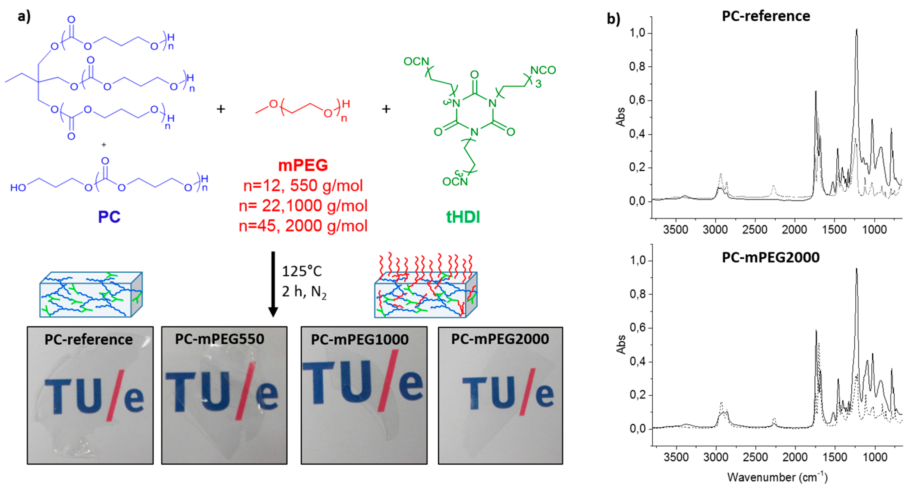
34]. Briefly, trimethylene carbonate (TMC) was used as monomer and a trifunctional alcohol, trimethylolpropane (TMP), was used as initiator, obtaining a polymer mixture composed of a ~66% of tri-branched and ~34% of linear polycarbonate (the PC polymer mixture chemical structures are represented in
Figure 1). This polymer mixture was always obtained due to the coexistence of two polymerization mechanisms, the Activated Chain End (ACE) and Activated Monomer (AM) mechanism. A complete characterization by NMR, GPC and MALDI was crucial to discriminate the polymer composition and characteristics, as the difference between the two types of polymers is only detectable by MALDI (full polymer synthesis and characterization details are given in
Section 2).
This approach allowed the preparation of metal-free polymers, with low Đ value, well-known chemical structure and composition and very high stability in aqueous conditions, as will be demonstrated. These are valuable characteristics when biomedical, pharmaceutical or non-toxic materials for green technologies are targeted.
3.2. Coatings Preparation and Characterization: Surface Wettability and Stability
The coatings solutions were prepared by combining stock solutions of the synthesized PC polymers with the different molecular weight mPEG hydrophilic dangling chains, mPEG550, mPEG1000 or mPEG2000, and the crosslinker tHDI, from now on referred as PC-mPEGy, where “y” represents the mPEG molecular weight, i.e., 550, 1000 or 2000 g·mol−1. A reference coating composed by PC and tHDI was also made in order to study the effect of mPEG chains in the polycarbonate coatings properties (named as PC-reference). The variation of mPEG with different molecular weight was done to investigate the influence of the dangling chain length in the coating features: hydrophilicity, anti-fouling properties and self-replenishing behavior.
Crosslinking of the coatings was done with thermal curing via the reaction between the tHDI isocyanate groups and the hydroxyl groups present in both the PC polymer precursors and the mPEG dangling chains, producing a polyurethane network (
Figure 1a).
The chemical crosslinking of the coatings was analyzed with FTIR by measuring the initial coating solution before curing and the obtained film after curing. PC-reference and PC-mPEG2000 FTIR spectra are shown in
Figure 1b as representative examples. After the curing reaction, the characteristic vibration bands of the isocyanate (υNCO ≈ 2300 cm
−1) and hydroxyl groups (υOH ≈ 3500 cm
−1) were no longer present and the new vibration bands assigned to the urethane bonds formation at (δNH ≈ 1500 cm
−1 and υNH ≈ 3400 cm
−1) were detected. It is worth noting that for some coatings, e.g., PC-mPEG2000 (
Figure 1b, bottom), a residual isocyanate peak remains after curing. This can be due to the slight excess of tHDI crosslinker added in the coating formulation (NCO:OH functional group mol ratio of 1.1) and the higher viscosity of mPEG2000, which has also a slight influence on the amount of extractable residues obtained in these coatings, as discussed below. Nevertheless, all the synthesized PC coatings were free of application defects, colorless and highly transparent after curing, as can be observed in
Figure 1a.
To investigate further the incorporation of the different components in the cross-linked network, extraction experiments were performed in water and acetone to determine the coatings mass loss (
Table 1). The coatings mass loss after curing is attributed to non-reacted or non-network incorporated components which dissolve into the extraction solvents. For both, acetone and water extraction, the coatings remained visually unchanged after the immersion time. When comparing the water and acetone weight loss values, a lower weight loss was observed in water for all the coatings, which was expected due to the better solubility of all the coating components in acetone. This was confirmed by the
1H-NMR analyses performed on the dried solid residues (
Figure S2, Supplementary Materials). In the residues from the acetone extract, traces of all the coating components, PC, mPEG dangling chains and tHDI crosslinker, were detected. For the residues of the water extracts, mPEG and tHDI were mostly found, since the PC polymer is nearly insoluble in water. Overall, the low amount of weight loss detected, reaching a maximum of six percent in acetone for PC-mPEG2000, confirms that covalently bonded coating networks were efficiently formed and are rather stable in the tested solvents.
The highest weight loss registered for PC-mPEG2000 coatings in both solvents can be related to an incomplete reaction of the isocyanate groups due to a lower availability of the hydroxyl groups, in view of the higher molecular weight of PEG2000, its higher viscosity and lower solubility, which ultimately affects more strongly the chain mobility and its incorporation to the network. This observation is also corroborated by the remaining isocyanate peak observed in the FTIR spectrum after curing (
Figure 1b), as discussed above.
After confirming proper network formation, the influence of the dangling chains on the coatings properties, i.e., water uptake, wettability and
Tg, was analyzed (
Table 1). The incorporation of the PEG-based hydrophilic dangling chains allowed tuning of the coatings hydrophilicity. The hydrophilicity of the coatings increased with the length of the dangling chains, as denoted by the ability of absorbing more water and the lower static water contacts angles obtained. This is in accordance with the expectation that the introduction of more hydrophilic ethylene oxide units in the network via the dangling chains will allow more water–polymer interactions via hydrogen bonding. As for the thermal properties of the coatings, a decrease in
Tg was observed when introducing mPEG, this decrease being more pronounced for the longer dangling chains.
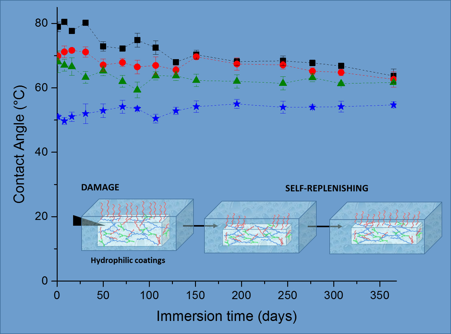
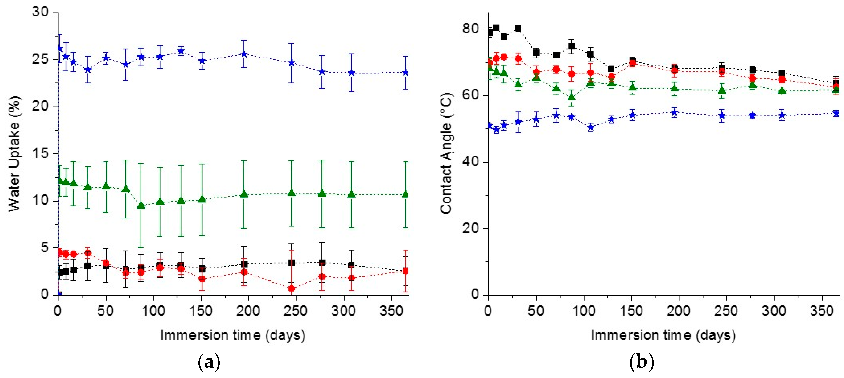
In the search for materials with long-time durability, the stability and appearance of the coating along with the surface wettability in time are important parameters. The stability of the coatings was estimated by measuring the water uptake in time. The cleavage of the urethane and carbonate bonds could lead to a more hydrophilic network and probably loss of the network structural integrity, meaning that a higher capacity of absorbing water and thus an increase in the water uptake value should be observed in time. On the other hand, the release of small coating fragments of coating into the solvent could also lead to a decrease in water uptake. As for the surface wettability, a decrease of the water contact angle would indicate the formation of more hydrophilic groups on the surface, most likely due to degradation as explained before. On the contrary, an increase in contact angle would indicate a loss of the hydrophilicity due to the loss of the hydrophilic dangling chains at the surface.
In spite of all these possible scenarios, the water uptake and contact angle of the PC coatings prepared remained remarkably constant over one year of immersion in water, as can be seen in
Figure 2, demonstrating the excellent stability of the coatings. Interestingly the coatings appearance was also the same as the initial coatings, keeping their integrity, transparency and not developing any color in time, which is a further indication of absent degradation (
Figure S3). The excellent stability of the coatings was further confirmed by the low weight loss of the coatings after one year immersion in water, reaching a maximum of only ~3.1% loss (
Figure S3). The most notable difference was observed for the reference coatings. After one year immersion, their water CA decreased to a value close to the one of the PC-mPEG500 and PC-mPEG1000. Since the water uptake (
Figure 2) and the mass loss (
Figure S3) of the reference coatings were not significantly changed, this CA change could be due to rearrangements in the polymer films and a higher exposure of the more hydrophilic segments of the polymer network to the water interfaces.
3.3. Evaluation of Anti-Fouling Properties
Biofouling is a complex process that involves several stages [
35]. In the first minute after immersion of a material in water proteins adsorb on the surfaces forming a conditioning film which establishes the proper environment (biofilm or slime) for the attachment of bigger organisms during the next stages, micro- and macro-fouling. The fouling problem is even more complex due to the fact that it is also influenced by external factors, like water salinity, oxygen concentration, temperature and light-exposure period, which vary across the globe and for the type of water [
1]. A simplified, laboratory-accessible way to evaluate the anti-fouling properties is to quantify the first stage of biofouling by measuring the protein adsorption on surfaces. Thus surfaces presenting a low protein adsorption value can be considered to be of high potential for anti-fouling since the prevention of primary phase of fouling (biofilm formation) ensures the impossibility of bigger organisms to adsorb and settle afterwards.
In this study, Fibrinogen (FB) was selected as model protein-foulant to evaluate the fouling potential of the PC coatings prepared. The quantification of the adsorbed FB was done by UV/Vis spectroscopy and making use of the characteristic absorption peak of these proteins at 280 nm, due to the presence of aromatic aminoacids in their chemical structure [
32,
33]. The coatings were fully covered with a known amount of a PBS solution of FB. The adsorbed proteins were quantified by determining the proteins remaining in the PBS solution (not-absorbed) after 24 h of incubation and with reference to a previously prepared calibration curve (see
Figure S1 in Supplementary Materials).
The FB adsorption value was determined to be very close to 10 µg·cm
−2 for all the coatings prepared which is normally considered as a low protein adsorption value in the related AF literature (
Table 2) [
24]. Such low protein adsorption values denote the very good stability of these coatings and their high potential for AF. In fact, the protein adsorption determination procedure was sometimes rather difficult and inconclusive due to the very low values measured. For this purpose the coatings were always measured in triplicate and with extra care to avoid contamination or any loss of material from the PBS solutions.
As can be seen from
Table 2, the introduction of the shortest mPEG hydrophilic dangling chains, mPEG550, resulted in the maximum decrease of protein adsorption value as compared to the reference. However, when increasing the coating hydrophilicity further, i.e., introducing the mPEG1000 or mPEG2000 chains, the protein adhesion values did not decrease further, with the protein adsorption value for these coatings very close to the value of the PC-reference coating. Hence, no clear correlation was found between the reference coatings and the increasing hydrophilicity via the introduction of mPEG dangling chains with different length. The presence of a mPEG molecular weight threshold value for which a minimum of protein adsorption value is found was also reported by others when using FB or other proteins like Bovine Serum Albumin (BSA) [
36,
37].
Although protein–PEG interactions have been widely studied, they are still far from being understood, and up to date there is not a clear explanation for this. A possible explanation which has been put forward for the lower efficiency of high molecular weight PEG relates either to the difficulty in achieving an optimum chain density at the surface due to possible entanglements (which is crucial for achieving a minimum protein adsorption value), or to the reduced mobility of the longer PEG chains [
37,
38]. Another possible explanation relies on the solubility of PEG in aqueous solutions with high salt concentrations, with particularly sensitivity to sodium and potassium phosphate salts, which are in fact present in the PBS solution used for the FB experiments [
39,
40]. Hence, our results showing inefficient protein adsorption reduction when using high molecular weight mPEG chains can be due to the reduced solubility of the mPEG in the PBS solution that hinders the water–polymer hydrogen bonding interactions and favors protein adsorption. Since we cannot determine in this work the accurate surface coverage of the coatings by the dangling chains, we can also not discard, however, the possibility of entanglements causing a lower chain density for the longest mPEG chains.
3.4. Self-Replenishing Behavior: Surface Hydrophilicity Recovery after Damage
To study the self-replenishing of the surface functionalities that guarantee the extended life-time of the hydrophilicity and the long-term use of the coatings, a controlled damage was introduced by a setup previously used for analogous self-replenishing coatings, as described elsewhere [
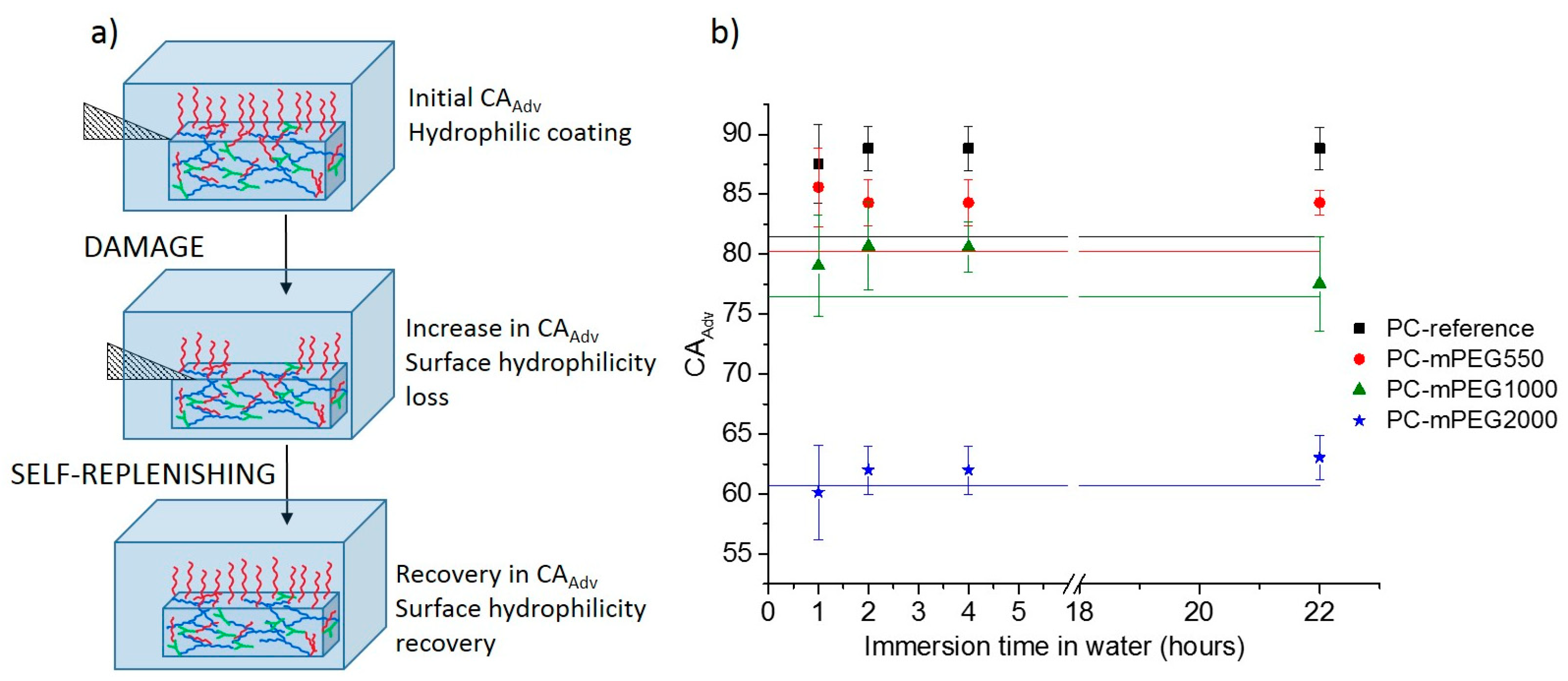
19]. Briefly, coatings were damaged with sand paper by applying a constant force and moving a specific weight back and forth on top of the coating for a specific number for 150 cycles. Afterwards the coatings were re-immersed in water at room temperature and at different recovery times, up to 22 h (
Figure 3a).
The thickness of the coatings was re-measured after the damage confirming the removal of a few micrometers of the most external top coating layers. The decrease in thickness was in the range of 0.5 ± 0.1 µm for the PC-reference coating in the range of 1.3 ± 0.2 µm for the softer mPEG containing coatings. The extent of recovery, concerning the initial loss of hydrophilicity, was evaluated by comparing the initial dynamic water contact angle (CA
Adv) of the water-soaked coatings before (
Figure 3a) and after damage, at different times of recovery in water, e.g., 1 h, 2 h, 4 h and 22 h (
Figure 3b) and quantified by calculating the Self-Replenishing Efficiency (
Table 2).
The damage experiments were first done on dry and also wet conditions (i.e., coatings immersed in water); however, only the results from the “dry-damage” could be used reliably, since during the “wet-damage” the coatings were often detached from the substrate hampering the analyses afterwards. Note that in real systems, a primer would probably be required to ensure the adhesion of the hydrophilic coatings to different substrates.
After the “dry damage” the coatings were immediately immersed in water to re-expose the newly created surfaces to water for the replenishing to take place. One of the limitations of this procedure is that after the damage and re-immersion in water, the coatings need to absorb water and swell; hence, it was not possible to estimate the extent of damage immediately after it takes place, and a reliable measurement of the water CA
Adv could only be done after one hour of immersion (
Figure 3). This was the time needed for the coatings to reach a maximum swelling ratio, as estimated from the swelling ratio (
Wt/
W0) profiles (
Figure S4, Supplementary Materials) and to minimize the effect of the water absorption on CA measurements.
An initial increase in the water CA
Adv after damage, i.e., loss of hydrophilicity, as compared to the initial water CA
Adv of the non-damaged coatings (solid straight lines in
Figure 3b), was observed for all coatings except for the PC-mPEG2000 (
Figure 3b).
For the PC-reference coating, an increase in CA
Adv was detected after damage and one hour of recovery in water. This increase in hydrophobicity can be explained by the fact that the damage imposed removes a few micrometers of the initial coatings surface, which may be slightly more hydrophilic than the bulk, as it may contain residual unreacted hydroxyl groups or more hydrophilic segments. Hence, when the bulk of the coatings is exposed by the damage, more hydrophobic segments will be at the new created surfaces increasing the newly measured water CA
Adv. Upon re-immersion in water, the PC-reference coating is not able to recover the initial hydrophilicity, not even after 22 h of immersion. This was expected since this coating does not contain additional hydrophilic dangling chains in the bulk, and the surface initially formed during the curing process with eventually more hydrophilic segments was lost during the damage, i.e., the PC-reference has no reservoir of hydrophilic components,
Figure 3b (black squares).
For the mPEG-containing coatings, a different replenishing behavior was found depending on the type of PEG used. For PC-mPEG550 and PC-mPEG1000 after damage and one hour recovery, a significant increase in CA
Adv was detected (
Figure 3b). After 22 h of immersion in water, the PC-mPEG550 presented a partial or null CA
Adv recovery in water, but the PC-mPEG1000 was able to recover the initial CA
Adv. The ability to recover the surface composition results from the combination of a low
Tg, that ensures the proper mobility of the dangling chains towards the water–coating interface, and the dangling chain length which also endows these mobility and interface reorientation [
41]. These coatings present similar
Tg values (
Table 1) thus showing that the mPEG dangling chain length plays a major role on the self-replenishing ability, i.e., only for PC-mPEG1000 the surface hydrophilicity was fully recovered, as demonstrated by the calculated SRE (
Table 2).
For PC-mPEG2000 coatings, no significant change of the water CA
Adv was detected either after the damage, or any of the recovery times (
Figure 3b). In this case, the combination of a much lower
Tg (
Table 1) and longer dangling chains seems to provide very stable hydrophilic coatings which can recover their hydrophilicity on damaged surfaces really fast (at least on a time-scale shorter than one hour, hence, not possible to detect with our procedure) upon immersion on water at room temperature. In fact, the excellent stability shown for all the PC coatings (
Figure 2), and in particular for the PC-mPEG1000 and PC-mPEG2000, already hinted that the surface composition of these coatings is very stable and/or fully replenishes in time, as the water CA remained constant throughout one year.
4. Conclusions
PC polymers were successfully used in the preparation of cross-linked hydrophilic coatings, which are colorless and transparent, with very low leachable amounts. The coatings present tunable hydrophilicity depending on the type (molecular weight) of mPEG dangling chains added to the cross-linked network, as well as an excellent long-term stability in water, as shown by the unchanged visual appearance and constant surface hydrophilicity after one year of immersion in water.
The proper selection of the coatings components confers an intrinsic self-replenishing driving force due to the hydrophobic/hydrophilic balance between the bulk and surface-oriented components. Once the hydrophilicity was reduced upon surface damage, the hydrophilic dangling chains in the bulk (i.e., in the reservoir) are exposed at the new wet and damaged surfaces and their reorientation towards the water coating interface takes place, minimizing the exposure of the more hydrophobic segments of the PC coatings. The combination of a low Tg and sufficient mPEG dangling chain length ensured the system mobility and the nearly 100% recovery of the surface hydrophilicity for the PC-mPEG1000 and PC-mPEG2000 coatings. Furthermore, these coatings showed an excellent stability in water throughout a one year evaluation period which may be due to the efficient preparation of cross-linked networks in which all the components (including the hydrophilic dangling chains) are covalently bonded, as well as to the self-replenishing processes taking place during the period that the coatings are immersed in water.
Finally, all the coatings exhibit low protein (Fibrinogen) adhesion on their surfaces, reaching a real minimum of protein adsorption for the PC-mPEG550, which demonstrates the high potential of application of these coatings as anti-fouling and self-replenishing protective films. Further protein adhesion tests and anti-fouling studies should be conducted with different proteins and aqueous solutions containing various electrolytes and salt concentrations, which could influence the characteristics of the coatings interfaces leading to different AF behavior under the different aqueous environments.


