1. Introduction
Gears are very often exposed to very harsh conditions. This concerns gears used in the transmissions of chain and belt conveyors working in coal and open pit mines. The harsh conditions are primarily related to the contamination of the gear oil with hard particles coming from coal and lignite. This can cause intensive abrasive wear, scuffing, and even pitting, limiting the life of gears.
One of the ways to increase the life of gears in mining conveyors is the deposition of a thin, wear-resistant, low-friction coating onto gear teeth [
1]. In the literature, one can find information on successful applications of various coatings to reduce the tendency of gears to scuffing [
2,
3,
4,
5], micropitting [
6], and to possibly reduce friction [
7,
8]. However, another form of dangerous wear—pitting—may be accelerated when the coating is used [
9,
10,
11]; although, in some cases, the resistance to pitting may be improved [
12,
13].
A variety of thin coatings have been tested. They can be divided into two groups: Non-DLC (DLC—diamond-like carbon) and DLC coatings. Tested non-DLC coatings are, for example, Nb–S [
14], MoS
2/Ti, C/Cr [
4], TiN, and CrN [
15]. Concerning DLC coatings, they are either doped coatings: W-DLC [
2,
15,
16,
17], Cr-DLC [
18], and Si-DLC [
19]; or non-doped coatings: a-C:H [
18,
19,
20] or ta-C [
19]. The review of the literature allows one to state that it is the DLC coating that is currently used in the majority of tribological research works.
Apart from testing thin coatings, it is also important to select a proper oil to lubricate the coated parts [
15]. For decades, a lot of research works have been devoted to investigating the interaction between the lubricating additives in the oil with the steel surface [
21,
22,
23,
24,
25,
26,
27,
28,
29,
30,
31,
32], and the mechanisms of the interaction between steel surfaces and lubricants are well recognized.
Concerning the interaction between the oil and the thin coating, the publications are less frequent [
15,
18,
33,
34,
35,
36,
37,
38] and have been mostly issued in the last 20 years. Unlike the oil-steel interactions, when testing coatings, one can find different statements and observations in the literature. Some authors point out an effect of the coating’s elemental composition, occurrence of the transfer of material between the samples, forming of protective films on the surface, or even chemical reactions of the coating with the lubricating additives in the oil.
In a review paper, Kalin et al. [
33] compared oil-coating interactions when lubricating with oils with a mineral, synthetic ester, and polyalphaolefin (PAO) base using various tribosystems. They stated that non-doped DLC coatings can react with different types of additives (e.g., a friction modifier (FM), antiwear (AW), and extreme-pressure (EP) additives), and that the hydrogen content in DLC coatings plays a crucial role in the tribological performance under lubricated conditions.
Michalczewski et al. [
15] performed four-ball scuffing tests, where all the balls were coated with a W-DLC coating, lubricated with a mineral oil with EP additives. After rubbing the coating off the upper ball, the researchers noticed the transfer of steel onto the coated surface of the lower balls, modified by the products of chemical reactions of sulfur and phosphorus coming from the EP additives.
Vlad et al. [
34] performed four-ball scuffing tests, where the upper ball was coated with a W-DLC coating, lubricated by a polyalphaolefin (PAO) oil with an AW additive. They observed the transfer of the coating onto the steel counter-face of the bottom balls and the reaction of the AW additive with the steel surface, generating a protective film, consisting of phosphates, oxides, and sulfides as reaction products.
Mistry et al. [
35] performed ball-on-disc tests with a W-DLC coating deposited on both test specimens, lubricated with PAO oil with AW and EP additives. On the worn surface, they identified wear-reducing compounds (zinc sulfide and tungsten carbide) as well as friction reducing compounds (e.g., tungsten sulfide), which formed as a result of coating-lubricant interactions.
Vengudusamy et al. [
19] conducted a test on the non-doped and doped DLC coatings deposited on the test specimens of a minitraction machine (MTM), lubricated with a mineral base oil. They stated that one of the reasons for the reduction in friction may be the formation of a thin oxygen-containing layer. On the other hand, according to Yang et al. [
37], performing pin-on-flat experiments of the W-DLC/cast iron tribosystem, lubricated with a PAO oil with AW and FM additives, the lubricant additives reduce the formation of tungsten oxides, which is a more brittle material, that could lead to the failure of the coating, as is seen in base oil lubrication.
Yang et al. [
38] conducted reciprocating pin-on-plate experiments on a W-DLC/cast iron tribosystem lubricated with an oil withAW and FM additives. They stated that the formation of MoS
2, by chemical decomposition from MoDTC, is dominant in such a system, rather than the possible formation of WS
2. Similar observations were done by Haque et al. [
20] by performing reciprocating pin-on-plate experiments of the non-doped DLC/cast iron tribosystem, lubricated with a PAO oil with AW and FM additives. They observed the formation of a low friction MoS
2 sheet and ZnO/ZnS compounds at the interface, as well as the formation of a ZDDP tribofilm containing Zn/ZnO/ZnS.
The most often used lubrication in tribosystems with DLC coatings are oils with a mineral or PAO base. Concerning increasingly used polyalkylene glycol (PAG) oils, there are only a few papers on their interaction with a DLC coating (e.g., [
39]).
In most of the works referred to above, lubricating oils were “model oils” (i.e., they were formulated by the researchers to control their chemical composition and more precisely identify the surface phenomena). However, where an application of the coatings to increase the life of gears is at stake, it is necessary to use commercial, fully-formulated gear oils, having the performance level and viscosity grade close to the oils used in specific applications. Only a minority of the research works concern the use of fully-formulated, commercial oils (e.g., [
1,
15,
40,
41,
42]).
In the research and development works, before verification (component) tests are performed (e.g., on gears), screening tests on model, simple specimens are very often carried out. This approach is suggested (e.g., in the works [
43,
44,
45,
46,
47]). The reason is that component (gear) tests are very expensive and time-consuming. For example, gear pitting tests may require time counted in months. This is why the majority of tribological experiments on thin coatings are carried out using model, simple specimens, especially when testing pitting [
15,
48,
49,
50,
51].
This paper presents an effect of fully formulated gear oils, intended for the lubrication of gears made of 18CrNiMo7-6 steel (where one gear will be DLC-coated) on abrasion, scuffing, and pitting. The gear oils used had three types of base oils: Mineral, PAO, and PAG. The tests were performed using model, simple specimens. A new, commercially available W-DLC/CrN coating was tested, developed from the point of view of reducing the negative impact of high cyclic stress.
The final aim of the research is to improve the durability of the planetary transmissions in mining conveyors.
2. Materials and Methods
For research on abrasive wear and scuffing, the T-09 pin and vee block tribotester was employed. This device was developed and manufactured at the Institute for Sustainable Technologies–National Research Institute in Radom, Poland.
The tested tribosystem is shown in
Figure 1.
The tribosystem consisted of two vee blocks pressed at a certain load P against the test pin that rotated at the constant speed of n (290 rpm), driven by the test shaft through the shear pin inserted in the hole. The shear resistance of all the shear pins was almost identical. The friction contact was lubricated by the oil poured into the reservoir equipped with a heater, where the contact area was immersed. The initial temperature of the oil was set up at the level of 70 °C, which corresponds to the temperature expected in the transmissions of mining conveyors.
The abrasion test was carried out according to ASTM D2625 [
52], Procedure A, slightly modified. First, the run-in procedure was performed—testing at 1334 N for 3 min. Then, the regular test was carried out. In the first phase, the load of 2224 N was applied for 1 min or up to failure. If no failure was observed, the load was increased to 3336 N, and the test was performed for the next minute or up to failure. If no failure was observed, the load was again increased to 4448 N and the test was performed until failure.
Failure was indicated by a sharp torque rise of 1.13 Nm above the steady-state value, or the breakage of the shear pin, or the inability to maintain the load, or exceeding 10,000 s of the total time excluding the 3-min run-in (i.e., 164 min).
The resistance to abrasion was expressed by the endurance (wear) life, which is the total time of the runs before failure occurs, excluding the 3-min run-in. It was adopted that a minimum of 3 test runs constitute the final result.
The scuffing test was carried out according to ASTM D3233 [
53], Method A. First, the run-in procedure was performed—testing at 1334 N for 5 min. Then, the regular test was carried out—the load was continuously increased up to failure or until the maximum load was attained.
Failure was indicated by breakage of the shear pin or the test pin.
The resistance to scuffing was expressed by the load at failure or a maximum attainable load. It was adopted that a minimum of 4 test runs constitute the final result.
A comparison of the load change in both tests is shown in
Figure A1. Acontinuous load increase (
Figure A1b) gives very harsh test conditions and differentiates scuffing tests from abrasion tests.
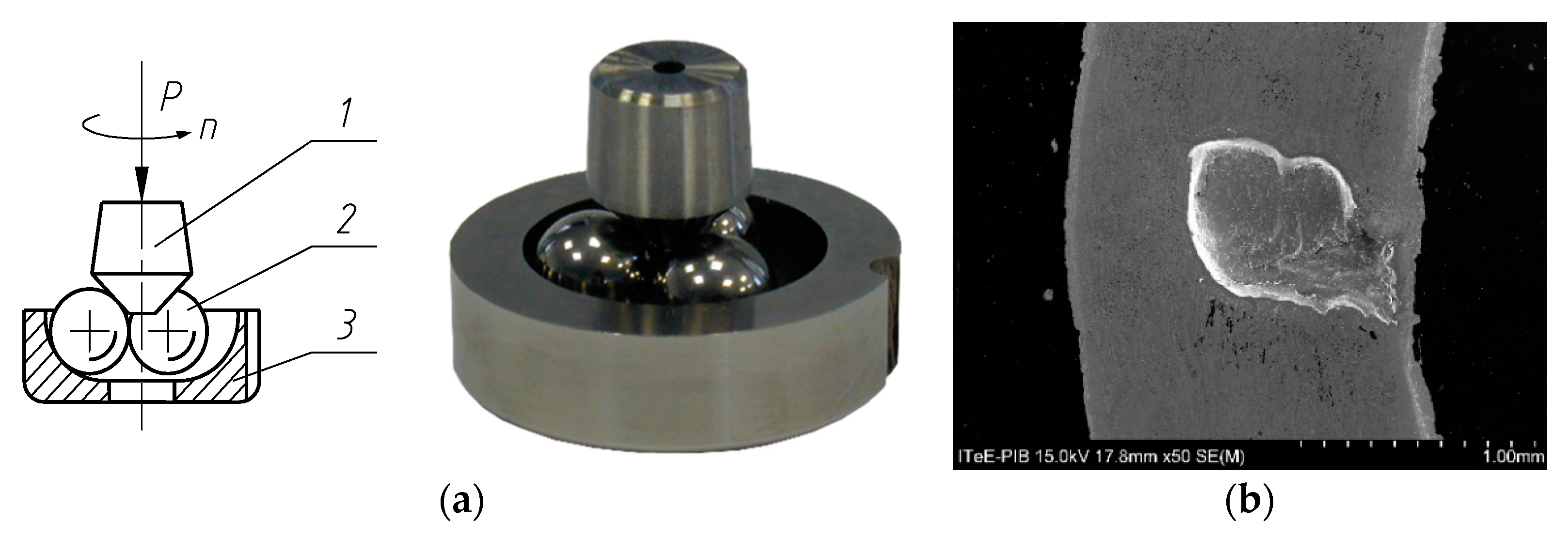
For research on pitting, the T-02U universal four-ball testing machine was employed. This device was developed and manufactured at the Institute for Sustainable Technologies–National Research Institute in Radom, Poland. In the tribosystem the top ball was replaced with a cone [
51].
The tested tribosystem and the SEM image of a typical pit on the cone are shown in
Figure 2.
Figure 2a shows that the tribosystem consisted of three balls (2) that were free to rotate in the special race (3) and were pressed at the required load
P against the cone (1). The cone was fixed in the ball chuck and rotated at the defined speed
n. The contact zone of the balls was immersed in the oil. The holder of the race (3) was equipped with a heater. As in the case of the previously described tests, the initial temperature of the oil was set up at the level of 70 °C.
The pitting test was performed according to IP 300 standard [
54]. Test conditions were as follows: Rotational speed of 1450 rpm, applied load of 3924 N (400 kgf), run duration until pitting occured, and the number of runs of 24. Only those runs for which pitting occurred on the cone were accepted. In each run, the time to pitting failure occurrence was measured.
After test completion, the 24 values (failure times) were plotted in Weibull co-ordinates (i.e., the estimated cumulative percentage failed against the failure time). Then, a straight line was fitted to the points. From the line, the fatigue life L10 was read off, which expresses the resistance to pitting. The value of L10 represents the life at which 10% of a large number of test cones would be expected to have failed.
The test pins, vee blocks, and cones were made of 18CrNiMo7-6 case-hardened steel, which is the material intended for the gears in mining conveyors. The hardness was 62 HRC. The roughness of the vee blocks and cones was Ra = 0.20 μm, and the pins was Ra = 0.52 μm. The balls and races (pitting tests) were made of 100Cr6 bearing steel.
The W-DLC/CrN, commercially available, antifriction coating was tested. The coating was deposited by reactive sputtering in the physical vapor deposition (PVD) process. One kind of specimen was coated (e.g., on the vee blocks (abrasion and scuffing tests) and on the cones (pitting tests)), leaving the counter-specimens uncoated. The reason for this is that, in the planetary transmissions of mining conveyors, only planetary pinions will be coated, leaving the ring and sun gears uncoated.
The microstructure of the coating revealed during qualitative glow-discharge optical emission spectrometry (GDOES)analysis is shown in
Figure 3.
The W-DLC/CrN coating represents an a-C:H:Me group.
Figure 3 shows that the coating consists of CrN adhesion layer adjacent to the steel substrate, followed by the WC interlayer, and then the WC/C layer (i.e., alternating lamellae of WC and a hydrocarbon layer doped with tungsten). WC/C layer exhibits antifriction properties. The producer of such coatings states that the friction coefficient at dry friction, when rubbing against a steel ball, is between 0.1 and 0.2. When the WC/C layer is worn away, the hard WC interlayer is exposed. This is followed by the exposure of CrN, and these layers have very good resistance to abrasion. The CrN layer is very ductile, and it additionally gives excellent support properties in cyclic loaded contacts. Actually, in the preliminary experiment, the coating used in this research gave a much better resistance to pitting than another DLC coating that was deposited on the adhesive layer of only chromium.
The basic properties of the W-DLC/CrN coating were the following: A thickness of 4.2 m, an adhesion in scratch tests of 151 N, a nanohardness of 12 GPa, a roughness Ra of 0.09 μm, and a roughness Rz of 1.04 μm. The thicknesses of the WC/C, WC, and CrN layers were the following, respectively: 1.9, 0.4, and 1.9 μm.
For lubrication, commercial industrial gear oils were used. They were a mineral oil, and two synthetic ones (i.e., one with a polyalphaolephine (PAO) base and one with a polyalkylene glycol (PAG) base, and all with the viscosity grade of VG 320. The most important difference is in theviscosity index (VI). For the mineral oil, VI = 95, for the PAO oil VI = 159, and for the PAG oil VI = 230. Such oils are used, for example, to lubricate the gears of mining conveyors.
To determine the features of the worn surface, the following analytical instruments were used: A field-emission scanning electron microscope (FE-SEM, SU-70, Hitachi, Tokyo, Japan), an energy dispersive spectrometer (EDS, Noran System 7, Thermo Scientific, Waltham, MA, USA), an optical profilometer (Talysurf CCI, Taylor Hobson, Leicester, UK), a stylus profilometer (Talysurf PGI 830, Taylor Hobson), an atomic force microscope (AFM, Q-Scope 250, Quesant Instrument Corporation, Agoura Hills, CA, USA), an optical microscope (MM-40, Nicon, Tokyo, Japan), and a microhardness meter (FM-800, Future-Tech Corp., Kawasaki, Japan). Prior to the microanalyses, the test specimens were washed with 95% n-hexane in an ultrasonic washer for 10 min, and then dried in the open air.
In reference to the EDS analysis, it was either qualitative analysis (surface maps for particular elements) or quantitative analysis(point analysis). Both types of analyses were performed at the accelerating voltage of 15 kV. For the quantification, the widely used correction method “Phi-Rho-Z” was employed. The quantitative analysis had no standards.
Concerning statistical analysis, for the results of the abrasion and scuffing tests, confidence intervals representing 95% probability were calculated. For the results of the pitting tests, confidence intervals representing 90% probability were calculated.
4. Discussion
4.1. Means of Analyses
To interpret the tribological results, surface elemental analyses and physico-mechanical analyses of the worn areas were conducted.
Figure A2 shows a photograph of the tested vee blocks and pin.
Figure A3 presents a photograph of the tested cones. In
Figure A2 and
Figure A3, white rectangles mark the places of surface elemental analyses.
4.2. Abrasion Tests
Figure 4, presented earlier, shows that the resistance to abrasion of the coating-steel tribosystem was much higher than for steel-steel, irrespective of the oil used. This is due to the action of the hard WC interlayer in the coating, and when WC is worn away, the CrN layer gives very good resistance to abrasion. However, the question is, “why did the PAG oil produce the worst result?”
Results of SEM/EDS surface analysis from the worn surfaces of the vee blocks is shown in
Figure 11.
In the case of the lubrication with the mineral oil, the outer layers of the W-DLC/CrN coating were worn away, namely, the low-friction layer of WC/C and the hard, wear-resistant interlayer of WC (having a total thickness of 2.3 μm), exposing the adhesive layer of CrN. For the PAO and PAG oils, the outer layers were partially worn. The coating removal was observed also in the earlier work by Michalczewski et al. [
15].
As in the above cited work [
15], the transfer of iron from the steel pin to the coated surface of the vee block due to friction was observed; although, in the case when the coated vee block was lubricated with the mineral oil, the transferred material was located mainly on the verges of the wear scar. The production of, for example, tungsten sulfide may be excluded, as suggested elsewhere (e.g., by Yang et al. [
38]), as the places of appearance of sulfur did not “overlap” the areas where tungsten was identified, as in the case of the PAO oil. Sulphur was, rather, “in line” with the traces of iron, which suggests that iron sulfide (FeS)was produced on the transferred layer of iron, or that this compound was transferred from the chemically changed surface of the test pin due to the chemical reactions of the EP additives in the oil with the steel.
Vlad et al. [
34] observed the transfer of the coating onto the steel counter-face. Thus, a possible transfer of the coating, identified by observing tungsten, to the surface of the test pin was also investigated.
Table 3 compiles the results of the EDS analysis of tungsten on the worn surfaces of the pins.
The results of the concentration of tungsten on the worn surface of a test pin working in the uncoated tribosystem may be considered to be a “background” signal. For the all tribosystems with the coated vee block, the maximum concentration of tungsten in the surface layer of the pins was higher than the background signal. This suggests the transfer of the external, low-friction layer of the coating, namely WC/C, to the pin surface, lowering the friction in this way and improving the results in the abrasion tests when the coated vee blocks were used. However, it does not explain the worse results obtained for the PAG oil.
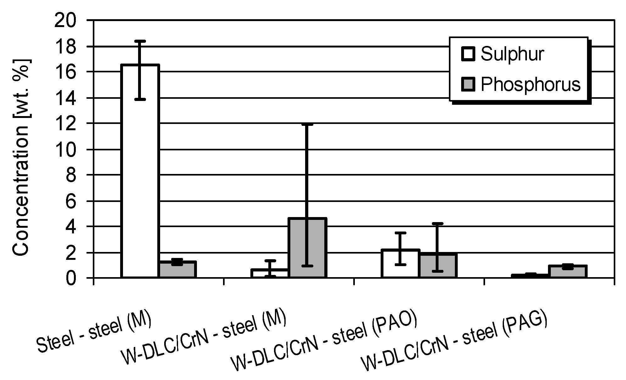
Results of the quantitative EDS analysis of the sulfur and phosphorus concentration in the worn surfaces of the vee blocks and pins are shown in
Figure 12 and
Figure 13, respectively. Each analysis was performed three times at different points. The scatters between the minimum and maximum values were added to the graphs.
The scatters of results showed a very inhomogeneous concentration of sulfur and phosphorus in the wear surface. The exception was the coating-steel tribosystem lubricated with the PAG oil.
It is known that the EP (extreme-pressure) additives (based on organic S–P compounds) form, for example, iron sulfide (FeS) [
21]. FeS compounds, apart from hampering the creation of adhesive bonds, with their five-fold lower shear strength and four-fold lower hardness than steel, facilitate shearing of the chemically modified surface asperities. The shear plane is transferred to the thin FeS layer, which protects the surface from tearing out the material from deeper layers, reducing the wear intensity. Under extreme pressure conditions, a dominating role is played by products of the chemical reaction of sulfur [
55].
In the steel-steel tribosystem, both on the worn surface of the vee blocks and of the pins, there were products of the reaction of sulfur, especially, with the steel surface—much more than when the coating was tested. In spite of this, the resistance to the abrasion of the coating-steel tribosystem was much higher than for steel-steel, irrespective of the oil used. As stated before, this is due to the action of the hard WC interlayer in the coating, and when WC is worn away, the CrN layer gives very good resistance to abrasion. Thus, the presence of the coating in the contact zone is of much greater significance than the chemical reactions with the oil.
Sulfur compounds found on the worn surface of the coated vee blocks were the result of chemical reactions of EP additives in the oil with the steel material, which was transferred from the test pin onto the vee block, and the transfer of chemically modified steel from the pin. Such a transfer was also observed in the earlier work [
15]. As stated by other researchers (e.g., Mistry et al. [
35] or Haque et al. [
20]), the appearance of sulfur compounds on the worn surfaces of the test specimens adds, beneficially, to the improvement of the tribological features. For the PAG oil, the concentration of sulfur in the worn area of the both test specimens was the lowest. It was accompanied by the relatively low concentration of phosphorus. This is a reason for the lowest resistance to abrasion, in this case, among the coating-steel tribosystems.
4.3. Scuffing Tests
Figure 7, presented earlier, shows that the resistance to scuffing of the coating-steel tribosystem was much higher than for steel-steel, irrespective of the oil used. The improvement of the resistance to scuffing was also observed by Kalin and Vižintin [
2], Martins et al. [
3,
4], and by the authors of this paper [
5] in case of the coated gears.
In this research, the improvement of the scuffing resistance was due to the action of the hard WC interlayer in the coating, and when WC was worn away, the CrN layer gave very good resistance to abrasion. A lower affinity of two different rubbing materials, than in the case of the uncoated contact, as well as the high hardness of the WC and CrN layers in the coating, led to a smaller tendency for the creation of adhesive bonds, which gave a lower tendency for scuffing. However, as in the abrasion tests, the question is, “why did the PAG oil produce the worst result?”
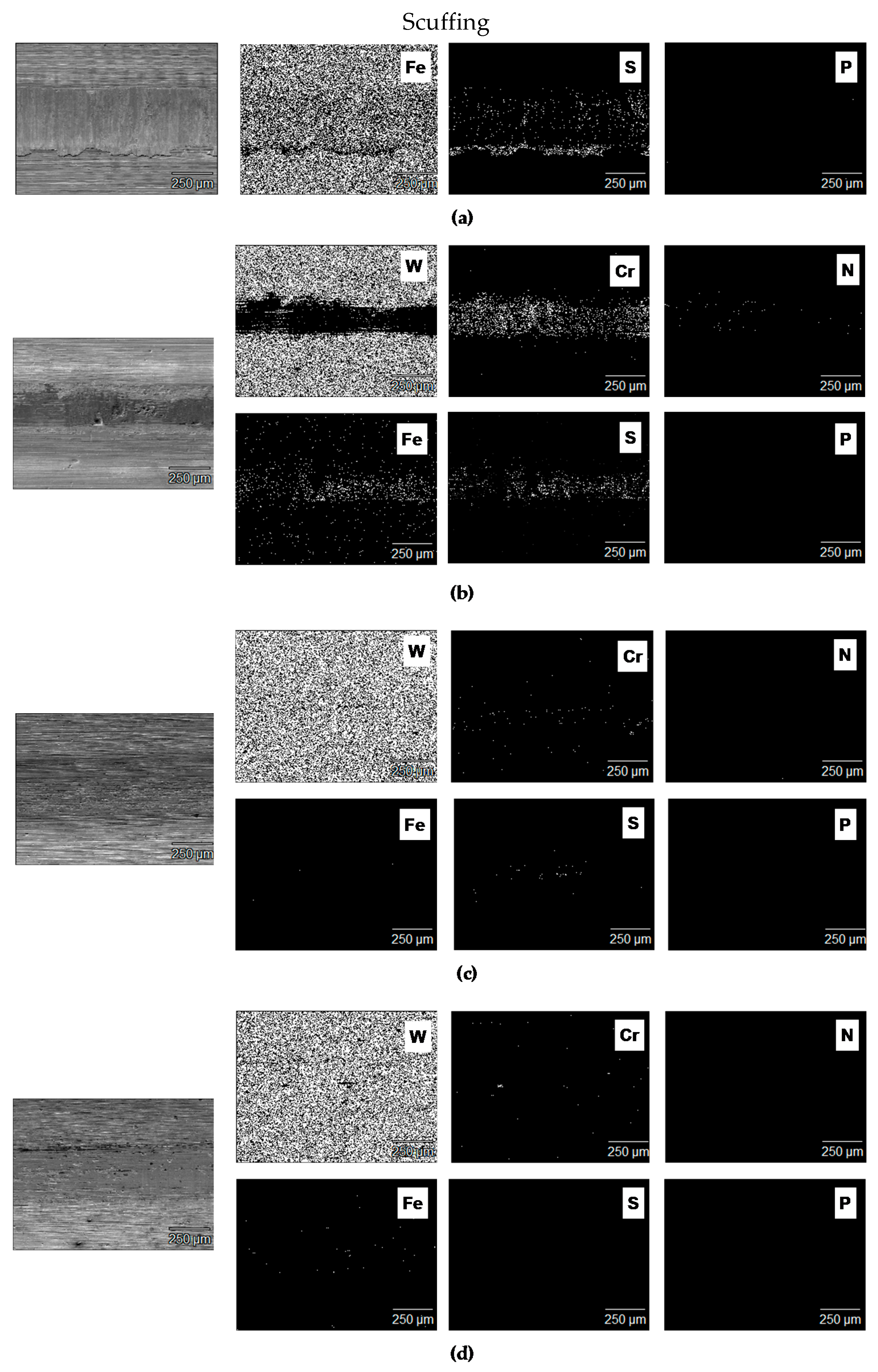
Results of SEM/EDS surface analysis from the worn surfaces of the vee blocks is shown in
Figure 14. Because, in the scuffing tests, in the case of lubrication by the PAO and PAG oils, the coating was unevenly worn along the wear scar, the analyses came from the dominating regions, in relation to the wear depth.
In the case of the lubrication with the mineral oil, the outer layers of the W-DLC/CrN coating were worn away, namely, the low-friction layer of WC/C and the hard, wear-resistant interlayer of WC (having a total thickness of 2.3 μm), exposing the adhesive layer of CrN. For the PAO and PAG oils, the outer layers were partially worn. The coating removal was also observed in the earlier work by Michalczewski et al. [
15].
The transfer of iron from the steel pin to the coated surface of the vee block due to friction was observed only in the case when the coated vee block was lubricated with the mineral oil. The production of, for example, tungsten sulfide, may rather be excluded, as suggested elsewhere (e.g., by Yang et al. [
38]), as the places of the appearance of sulfur did not “overlap” the areas where tungsten was identified, as in the case of the mineral oil lubricating the tribosystem with the coated vee block. Sulfur was, rather, “in line” with the traces of iron, which suggests that iron sulfide (FeS) was produced on the transferred layer of iron, or that this compound was transferred from the chemically changed surface of the test pin due to the chemical reactions of the EP additives in the oil with the steel.
As mentioned earlier, Vlad et al. [
34] observed the transfer of the coating onto the steel counter-face. Thus, a possible transfer of the coating, identified by observing tungsten, to the surface of the test pin was also investigated.
Table 4 compiles the results of the EDS analysis of tungsten on the worn surfaces of the pins.
The results of the concentration of tungsten on the worn surface of the test pin working in the uncoated tribosystem may be considered to be a “background” signal. For the tribosystems with the coated vee block lubricated with the PAO and PAG oils, the maximum concentration of tungsten in the surface layer of the pins was bigger than the background signal. This suggests the transfer of the external, low-friction layer of the coating, namely WC/C, to the pin surface, lowering the friction in this way and improving the results in the scuffing tests when the coated vee blocks were used. However, as in the abrasion tests, it does not explain the worst result obtained for the PAG oil.
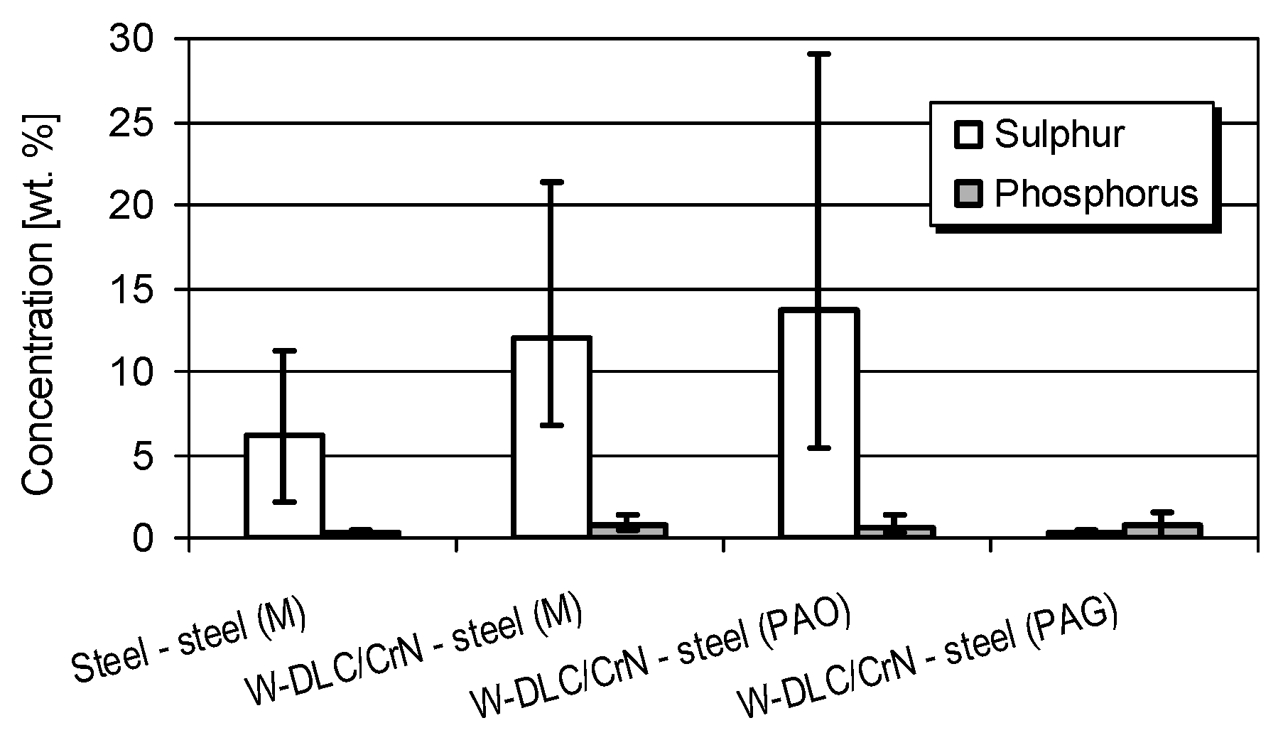
Results of the quantitative EDS analysis of the sulfur and phosphorus concentration in the worn surfaces of the vee blocks and pins are shown in
Figure 15 and
Figure 16, respectively. Each analysis was performed three times at different points. The scatters between the minimum and maximum values were added to the graphs.
As in the abrasion tests, the scatters of results showed a very inhomogeneous concentration of sulfur and phosphorus in the worn surface.
Under extreme pressure conditions during the scuffing tests, a dominating role was played by products of chemical reactions of sulfur [
55], and organic compounds containing sulfur were more reactive under such conditions. Therefore, in almost all cases, the concentration of sulfur was much higher than phosphorus, unlike in the abrasion tests.
As in the abrasion tests, in the steel-steel tribosystem, in the worn area on the coated vee blocks, there were products of the reaction of sulfur with the steel surface—more than on the coating surface. In spite of this, the resistance to the scuffing of the coating-steel tribosystem was much higher than for steel-steel, irrespective of the oil used. As it was stated before, this was a result of the lower affinity of two different rubbing materials, than in the case of the uncoated contact, as well as the high hardness of the WC and CrN layers in the coating, leading to a smaller tendency forthe creation of adhesive bonds and; therefore, there was a lower tendency for scuffing. Thus, as in the abrasion tests, the presence of the coating in the contact zone was of much greater significance than the chemical reactions with the oil.
Sulfur compounds found on the worn surface of the coated vee blocks were the result of the chemical reactions of EP additives in the oil with the steel material, which was transferred from the test pin onto the vee block, and the transfer of chemically modified steel from the pin. Such a transfer was also observed in the earlier work [
15]. As also stated by other researchers (e.g., Mistry et al. [
35] or Haque et al. [
20]), the appearance of sulfur compounds on the worn surfaces of the test specimens adds beneficially to the improvement of the tribological features. The appearance of sulfur compounds in the friction zone, in the case of the coating-steel contact, adds to the prevention of scuffing.
For the PAG oil, the concentration of sulfur in the worn area of both test specimens was the lowest. This was the reason for the lowest resistance to scuffing, in this case, among the coating-steel tribosystems.
4.4. Pitting Tests
Figure 9, presented earlier, shows that, when the coating was deposited on the test cone, the resistance to pitting dropped significantly, irrespective of the oil used. It was also shown that the mineral and PAG oils exhibit similar resistance to pitting. The PAO oil gave a slightly worse result.
The reduction of the resistance to pitting was also observed by Fujii et al. [
9] and by the authors of this paper [
10,
11] in case of the coated gears.
Results of SEM/EDS surface analysis from the worn surfaces of the test cones is shown in
Figure 17.
As can be seen from
Figure 17, irrespective of the oil used, the outer layers of the W-DLC/CrN coating were worn away, namely, the low-friction layer of WC/C and the hard, wear-resistant interlayer of WC (having a total thickness of 2.3 μm), exposing the adhesive layer of CrN. It was stated before that very big depths of the wear tracks on the coated cones were a result of plastic deformation of the substrate material. However, the presence of CrN layer is possible, because it is very ductile and adapts easily to the plastically deformed steel.
Results of quantitative EDS analysis of sulfur and phosphorus from the worn surfaces of the test cones are shown in
Figure 18. Each analysis was performed three times at different points. The scatters between the minimum and maximum values were added to the graphs.
Unlike in the sliding contact, during the pitting tests, EP additives in the oil may have played an adverse role, because their high corrosion aggressiveness may lead to creation of numerous depressions and micropits on the lubricated surface, being potential nuclei for “macropits”, reducing, in this way, the fatigue life. This was observed by, for example, Torrance et al. [
56] and Tuszynski [
57]. However, in the work by L’Hostis et al. [
58], it was stated that a sulfur-rich film is formed at the tip of the crack. This film can act as both a barrier film towards hydrogen permeation within the metal and/or as an inhibitor of oil decomposition. The latter is associated with the nascent surface’s ability to limit hydrogen generation. Without such hydrogen embrittlement, crack propagation is slowed down.
Mild friction conditions in the rolling contact during the pitting tests did not promote the chemical reactions of the EP additives in the oil with the steel surface. The concentration of sulfur and phosphorus in the surface layer was practically negligible. Thus, the better resistance to pitting given by the steel-steel tribosystem, than the coating-steel, irrespective of the oil used, can be explained from a physico-mechanical point of view.
The microhardness profiles in the surface layer were determined (
Figure 19). The analyses were performed along three different lines. The confidence intervals representing 95% probability were calculated and included in the graphs.
From
Figure 19, it was evident that, during the coating deposition process at the temperature of about 220–250 °C, due to phase transformations in the steel substrate, the microhardness dropped below the level observed for the uncoated steel. At the zone near the surface, which is most important for the fatigue life, the microhardness after deposition of W-DLC/CrN was lower than in the case of the uncoated sample. This correlates with the fatigue lives shown in
Figure 9; the lower the near-surface microhardness, the lower the fatigue life.
Another possible reason for the reduction of the fatigue life by the coating is related to the coating surface (
Figure 20).
One could observe numerous droplets on the surfaces of the coating, which can be considered defects that initiate pitting.
Yet another reason for the decrease of the pitting resistance is related to the coating and substrate residual stress. Vackel and Sampath [
59] found that coatings with higher compressive residual stress, hardness, and microstructural density enhanced the fatigue life of the coated specimens. However, coatings with tensile residual stress and somewhat weaker properties (hardness and stiffness) incurred a fatigue debit in the system. Varis et al. [
60] observed that good fatigue performance was related to the compressive stress state of the substrate.
The phase transformations in the substrate due to coating deposition can cause a decrease in the residual stress, being an additional factor of the pitting acceleration in this research.
5. Conclusions
The final aim of the research was to improve the durability of the planetary transmissions in mining conveyors by the antifriction coating deposited on gear teeth.
The paper presents the results of the selection of the gear oil intended for gears made of case-hardened 18CrNiMo7-6 steel. The tests were performed using model, simple specimens.
The W-DLC/CrN antifriction coating was tested, representing an a-C:H:Me group. The coating was deposited on one of the specimens in the tribological system (e.g., on the vee blocks (abrasion and scuffing tests) and on the cones (pitting tests)), leaving the counter-specimens uncoated.
For lubrication, commercial industrial gear oils were used. They were the mineral oil, and two synthetic ones; one with a PAO base and one with a PAG base, and all with the viscosity grade of VG 320.
For the three gear oils lubricating the (W-DLC/CrN)-steel tribosystem, the resistance to abrasion notably rosein comparison with the steel-steel tribosystem lubricated with the mineral oil. The mineral and PAO oils gave the same results. PAG oil gave the worst result.
A decisive reason for the very good features of the coating-steel tribosystem in the abrasion tests is related to the action of the hard WC interlayer in the coating, and when WC is worn away, the CrN layer giving very good resistance to abrasion. The behavior of the oil depends on the chemical reactions of its EP additives with the surface of the test pin, especially. For the PAG oil, the concentration of sulfur in the worn area was the lowest. This is the reason for the lowest resistance to abrasion, in this case, among the coating-steel tribosystems.
For the three gear oils lubricating the (W-DLC/CrN)-steel tribosystem, the resistance to scuffing significantly rose in comparison with the steel-steel tribosystem lubricated with the mineral oil. The highest resistance to scuffing was given by the mineral and PAO oils. Similar to the behavior during the abrasion tests, PAG oil gave the worst result.
A decisive reason for the very good features of the coating-steel tribosystem in the scuffing tests is the lower affinity of two different rubbing materials, than in the case of the uncoated contact, as well as the high hardness of the WC and CrN layers in the coating, leading to a smaller tendency for the creation of adhesive bonds and; therefore, there was a lower tendency to scuffing.
As in the case of the abrasion tests, the behavior of the oil depends on the chemical reactions of its EP additives with the surface of the test pin, especially. For the PAG oil, the concentration of sulfur in the worn area was the lowest. This is the reason for the lowest resistance to scuffing, in this case, among the coating-steel tribosystems.
When the coating was deposited on one specimen, the resistance to pitting significantly dropped, irrespective of the oil used. The mineral and PAG oils exhibited similar resistance to pitting. The PAO oil gave a slightly worse result.
Unlike during the abrasion and scuffing tests performed in pure sliding contact, mild friction conditions in the rolling contact during the pitting tests did not promote the chemical reactions of the EP additives in the oil with the surface. Thus, the better resistance to pitting given by the steel-steel tribosystem than the coating-steel, irrespective of the oil used, can be explained from a physico-mechanical point of view. During the coating deposition process, due to phase transformations in the steel substrate, the microhardness dropped below the level observed for the uncoated steel. This correlates with the fatigue lives; the lower the near-surface microhardness, the lower the fatigue life.
To conclude, taking into consideration various criteria (i.e., the resistance to abrasion, scuffing, wear, and roughness of the test specimens), the PAO gear oil is well suited for the lubrication of the (W-DLC/CrN)-18CrNiMo7-6 tribosystem. Although this oil gave a slightly worse resistance to pitting than the other oils lubricating the coating–steel contact, the decisive reason for such a statement is that PAO exhibits a much better viscosity index than mineral oils, which is desired in the very extreme working conditions of mining conveyors. Such a material combination has a great application potential, since it gives the desired high resistance to abrasion and scuffing.

 ,
, 


