Effect of Multiple-Pass Friction Stir Processing on Hardness and Corrosion Resistance of Martensitic Stainless Steel

1
Institute of Applied Physics and Materials Engineering, University of Macau, Macau 999078, China
2
Department of Electromechanical Engineering, University of Macau, Macau 999078, China
*
Author to whom correspondence should be addressed.
Coatings 2019, 9(10), 620; https://doi.org/10.3390/coatings9100620
Submission received: 28 August 2019
/
Revised: 23 September 2019
/
Accepted: 24 September 2019
/
Published: 27 September 2019
(This article belongs to the Special Issue Recent Advances in Friction Stir Processed Coatings)
Abstract
:In the present study, the influence of multi-pass friction stir processing (FSP) of AISI 420 martensitic stainless steel on the microstructure, hardness, and corrosion behavior was investigated. Similar to single-pass FSPed 420, the multi-pass FSPed specimens with different overlapping ratios incurred microstructural change at the center and retreating side of the second track with martensite, retained austenite, and chromium carbides. Overlapping of the two successive tracks in the multi-pass FSPed 420 led to back-tempering and a local drop in hardness at the advancing side of the second track. The precipitation of chromium carbides in the tempered regions of the multi-pass FSPed specimens became the active sites for preferential corrosion attack in the 3.5 wt.% NaCl solution at 25 °C.
1. Introduction
Friction stir welding (FSW) is a solid-state joining technology, which was invented at The Welding Institute (TWI), United Kingdom (UK) in 1991 [1,2]. Friction stir processing (FSP) was developed based on the working principle of FSW by Mishra et al. [3]. In FSP, a non-consumable rotating tool is plunged into a workpiece and moves along the required regions [2]. The translation of the rotating tool creates a characteristic asymmetry between the two sides of the processed zone, one is the advancing side (AS), where the direction of the tool rotation is the same as that of the tool translation, and the other one is the retreating side (RS), where the direction of the tool rotation is opposite to that of the tool translation [4]. FSP is applied for various purposes including fabricating surface composites [5], microstructural homogeneity [6,7], surface modification or hardening [8], and grain refinement [9].
Martensitic stainless steels (MSSs) are commonly used for manufacturing components with excellent mechanical properties but moderate corrosion resistance. MSSs are mainly used for mixer blades, offshore platforms for oil extraction, and cutting tools [10]. However, the annealed MSSs are not supposed to be used directly due to the presence of comparably soft and low-strength ferrite and carbides [11]. Consequently, MSSs are commonly used after conventional heat treatment, and their hardness can be enhanced. However, conventional hardening inside a furnace may not be suitable for large components. Moreover, brittleness and cracking are common problems in the heat-treated parts quenched at a very high cooling rate. As only the localized regions of an engineering component in tribological contact require high hardness and wear resistance, its surface has to be thermally treated while the internal core should be kept tough. Hardening using flame, induction, laser beam, and FSP are the alternative methods for improving the hardness and wear resistance of the surface. Nevertheless, the shortcoming of flame hardening is the possibility of part distortion, while high-frequency induction hardening requires close and precise coupling between the part and the coil [12]. Although laser transformation hardening can avoid thermal distortion, the size of hardened depth is limited by the dwell time and laser power density [13]. For achieving larger hardened depth, the problems of oxidation, melting, or vaporization of the surface often accompany the increasing laser power density and dwell time. Compared with these methods, FSP can accurately control hardness of the processed zone by optimizing the tool design and processing parameters [14].
In practice, a certain degree of overlapping of consecutive single passes (i.e., multi-pass) is required in FSP for achieving large area coverage [15]. The impact of multi-pass FSPed high-carbon steel (AISI 1080) on the friction and wear performance was investigated by Aldajah and his co-workers [15]. Improvement in wear resistance of the high-carbon steel by FSP was due to reduced plasticity of the near-surface material during sliding contact. Puli and Janaki Ram [16] reported that a single track of friction-surfaced AISI 440C coating exhibited superior corrosion resistance as compared to the conventional heat-treated sample, but no report on the corrosion behavior of the multi-pass can be found in the literature. On the other hand, the effect of multi-pass FSP on the microstructure and corrosion behavior of pure Ti in 0.5 M H2SO4 solutions was reported by Fattah-Alhosseini [17]. It was found that the grain size could be decreased to submicron size upon increasing the number of successive FSP passes because of severe plastic deformation and continuous dynamic recrystallization. Potentiodynamic polarization tests of the FSPed pure Ti showed that grain refinement resulted in a decrease in both corrosion and passive current densities, as well as a noble shift in corrosion potential.
According to a previous study on single-pass FSPed AISI 420 done by the present authors [18], the heat input was found to be higher in the AS and center than that in the RS. In the whole processed area, RS was more active in the corrosive medium due to some undissolved carbides dispersed in the martensite matrix. The region which was depleted in Cr acted as the initiation site for pitting. As a result, pitting corrosion was more severe in the RS of the FSPed zone because of a micro-galvanic effect [18]. On the other hand, Leal et al. reported that the defects including the tunnel or cavity left in single-pass FSWed aluminum alloys could be removed by a second overlapping pass [19]. However, the effect of multi-pass FSP on corrosion behavior and hardness change of MSSs cannot be found in the literature. Overlapping ratio was reported to be a key parameter of laser transformation hardening of AISI 420 for achieving required surface hardness and maintaining corrosion resistance of overlapped regions [20]. In this study, the effect of overlapping ratio on the microstructure, hardness, and corrosion properties of the multi-pass FSPed AISI 420 was investigated. The results for as-received, conventionally heat-treated, and single-pass FSPed AISI 420 were also included for comparison.
2. Experimental details
2.1. Materials
In this work, an annealed AISI 420 martensitic stainless-steel plate (with dimensions of 50 mm × 100 mm × 6 mm) was used for FSP. The composition of AISI 420 in weight percentage (wt.%) is shown in Table 1. In addition to FSPed 420, annealed 420 (designated as AR420) and conventional hardened 420 (heated at 1000 °C for 1 h, followed by water quenching) (designated as AQ420) were investigated for comparison purposes.
2.2. Friction Stir Processing (FSP)
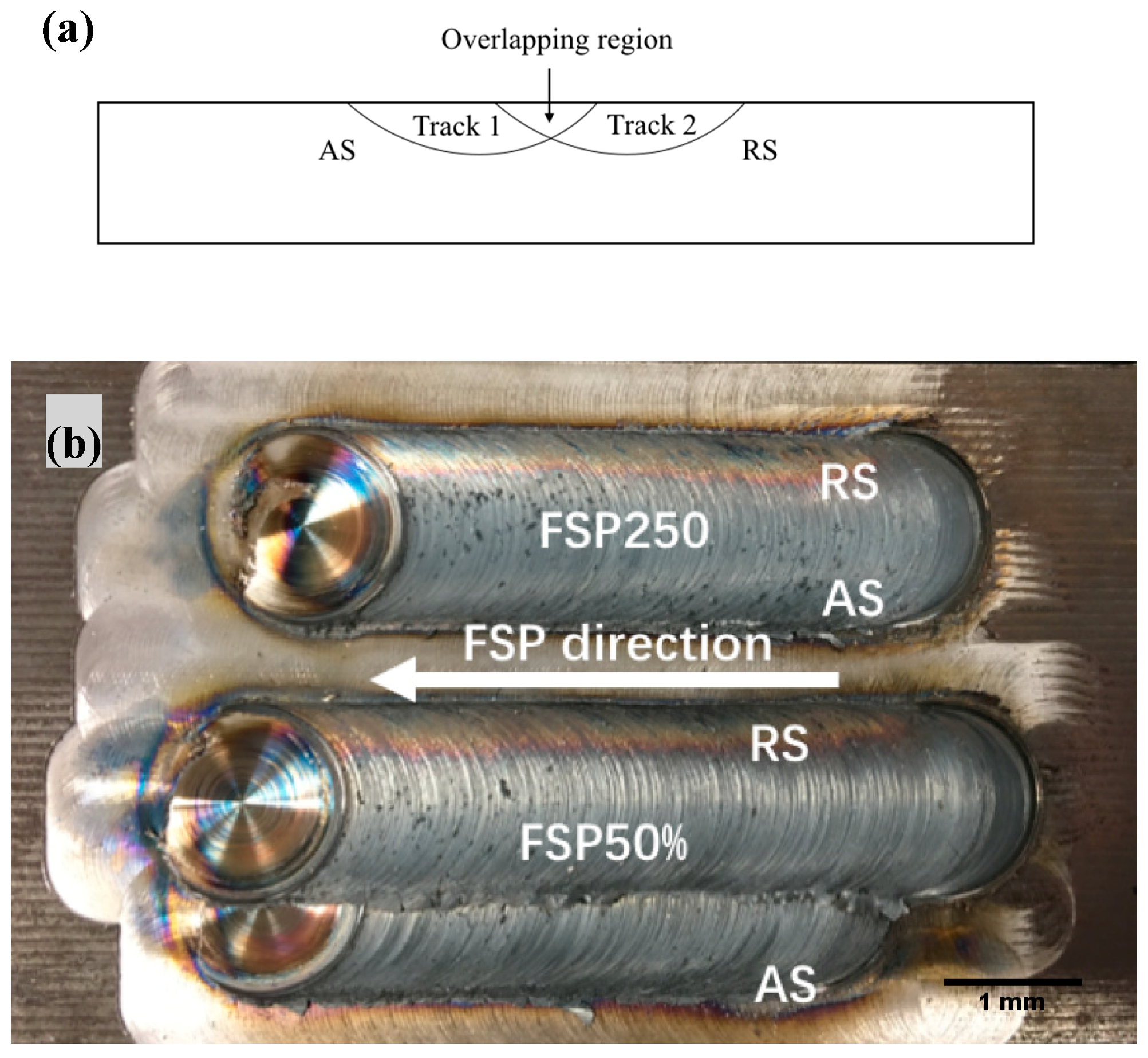
FSP of AISI 420 was conducted using an FSW machine (FSW-TS-M16, Beijing, China) manufactured by China FSW Center. The stirring tool for FSP was made of W–Re alloy with a 15-mm-diameter shoulder without pin. It was tilted at 1.5° and plunged into the AISI 420 plates at a depth of 0.1 mm. To avoid oxidation of the surface of the specimens, FSP was carried out in an Ar shielding atmosphere with a flow rate of 15 L/min. The experimental set-up for FSP was reported elsewhere [18]. A rotational speed of 2000 rpm and traverse speed of 250 mm/min of the stirring tool were used as the processing conditions for achieving higher hardness and corrosion resistance [18]. The schematic diagram for multi-pass overlapping of two FSPed tracks is shown in Figure 1a. After the first pass and cooling, the second track was overlapped with the first one. The overlap ratio (OR) of the multi-pass FSPed specimen is defined as follows [21]:
where d is the width of the single-pass track, and l is the distance between centers of the successive passes. In this study, ORs of 25%, 50%, and 75% were achieved, and the specimens fabricated in these processing conditions were designated as FSP25%, FSP50%, and FSP75%, respectively. The effect of OR on the properties of the multi-pass FSPed specimens was investigated.
2.3. Metallographic and Microstructural Studies
The specimens were cross-sectioned, mounted, and polished with 1-µm diamond paste and then etched with acidified ferric chloride solution for revealing the microstructure. The microstructure was investigated using an optical microscope (OM) and a scanning electron microscope (SEM, Hitachi S-3400N, Tokyo, Japan). The phases were identified using an X-Ray diffractometer (XRD, Rigaku MiniFlex 600, Tokyo, Japan) with a Cu Kα source. The scan rate used was 1°/min with 2θ ranging from 40° to 100°. The analysis of grain size and content of retained austenite of the FSPed samples was carried out using a field-emission SEM (Zeiss Sigma, Oberkochen, Germany) equipped with an electron backscatter diffraction (EBSD) detector. Aztec HKL from Oxford Instruments software (Oxford, England), Channel 5-Tango, was used for indexing and post-processing EBSD maps. EBSD can distinguish different phases through different diffraction patterns which occur when a stationary electron beam interacts with a tilted crystalline sample.
2.4. Hardness Test
The hardness profiles of the specimens were evaluated using a Vickers hardness tester (Wilson VH3100, Lake Bluff, IL, USA) at a load of 1 kg and load time of 10 s, conforming to ASTM standard E384 [22]. At least three trials along the centerlines of the FSPed zones in the transverse direction, and 0.2 mm below the top surface in the longitudinal direction were carried out for every specimen.
2.5. Corrosion Test
Potentiodynamic polarization tests in 3.5 wt.% NaCl solution were done with a Princeton Applied Research VersaStat II potentiostat conforming to ASTM Standard G61-86 [23]. The solution was open to air, and the temperature was kept constant at 25 ± 1 °C using an electronic water bath. The specimens were ground with the 1000-grit emery papers. A saturated calomel electrode (SCE) was used as the reference electrode, and two parallel graphite rods served as the counter electrodes. An initial delay of 120 min prior to polarization was adopted for the specimen to reach a steady-state condition at free corrosion potential (Ecorr vs. SCE). Then, the potential scan began at 200 mV below the Ecorr vs. SCE and was increased in the noble direction at a rate of 0.167 mV/s and terminated at a current density of 1 mA/cm2. From the polarization curves, the free corrosion potential (Ecorr vs. SCE) and the corrosion current density (Icorr) were extracted by Tafel extrapolation, and the pitting potential (Epit vs. SCE) was determined at the inflection point. At least three polarization tests were carried out for all specimens.
3. Results and Discussion
3.1. Microstructure
Figure 1b shows the typical single-pass FSPed specimen (FSP250) and multi-pass FSPed specimen (FSP50%). After a first track was produced, a second parallel pass was processed in the same direction by shifting in a distance (l) away from center of the first track. The AS of the second track was overlapped over the RS of the first one, and both tracks were produced in the same direction. According to Gandra et al. [24], the characteristics of the FSPed surface are highly influenced by the overlapping direction because of the asymmetric nature of material flow. The aim of overlapping the AS of the second track over the RS of the first track is to compensate for the inadequate heat produced at the RS of the first track [18].
From the previous study of the present authors, AR420 was found to mainly contain α-ferrite and precipitated carbide particles (M23C6) [18]. When AR420 was heated above the austenitizing temperature, the α-ferrite and M23C6 were transformed into austenite (α), which was then transformed into needle-shaped martensite (α’) after water quenching (designated as AQ420 with small undissolved M23C6 dispersed in the martensitic matrix [18]. The grain sizes of ferrite in AR420 and martensite in AQ420 were found to be 4 µm and 2 µm [18]. Figure 2a shows the cross-sectional view of the single-pass FSPed 420 (FSP250) fabricated at 2000 rpm and 250 mm/min. The width and depth of the FSPed zone were 14.7 and 1.7 mm, respectively. The FSPed zone was basin-like, and the AR and RS were not symmetric. The AS was deeper than that of the RS because the heat generation of the stirring tool at the AS was more than that at the RS. The flow of material at the AS around the stirring tool underwent more thermal exposure and severe deformation because the tangential component of rotation and translational speeds were in the same direction. Avila et al. reported that the peak temperature at the AS was slightly higher than that at the RS [25]. Moreover, the difference between AS and RS becomes more significant as the translational speed increases [18].
The cross-sectional views of the multi-pass overlapped specimens (FSP75%, FSP50%, and FSP25%) are shown in Figure 2b–d. No pore or crack was found in the cross-sections of the specimens due to sufficient heat generation for softening the material and strong plastic flow in the FSPed zones [26]. An overlap ratio of 75% produced a larger overlapped area (indicated by white dashed lines in Figure 2b), but promoted an FSPed layer with more uniform hardened depth. On the contrary, the specimen processed with an overlap ratio of 25% showed a small overlapped area (indicated by white dashed lines in Figure 2d) with a non-uniform hardened depth.
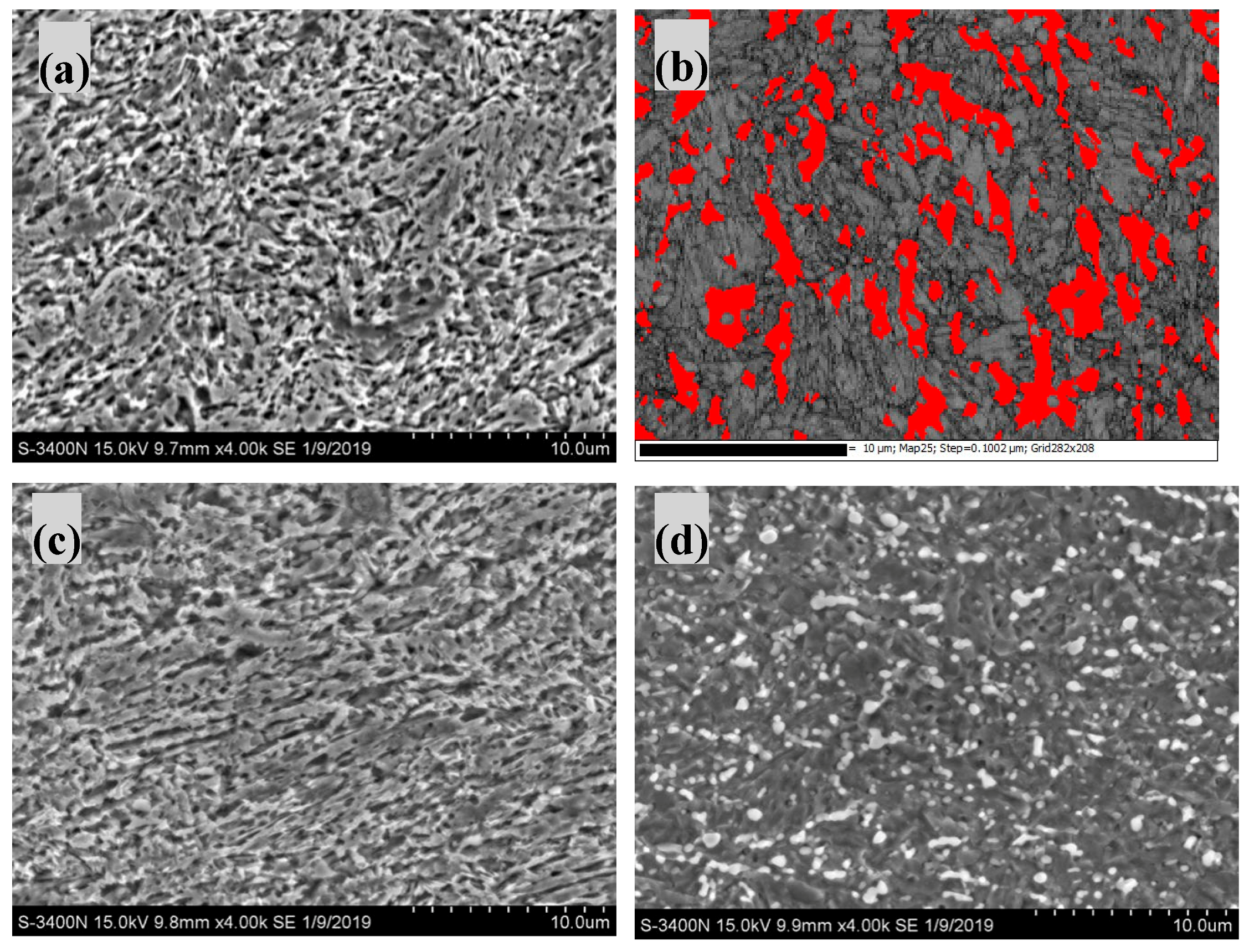
For the single-pass FSPed specimen (FSP250), the SEM micrographs of the AS, center, and RS, and the XRD pattern of the center are shown in Figure 3 and Figure 4, respectively. Figure 3b shows the EBSD band contrast superimposed with the phase maps (the red phase is austenite) at the AS. By analyzing the EBSD phase map, the AS of FSPed was found to contain 17.6% retained austenite. The AS and center mainly contained martensite and some retained austenite [18]. In addition to martensite, some undissolved carbides (M23C6) could be clearly seen in the RS due to incomplete austenization (Figure 3d and Figure 4) [27]. Compared with AQ420, the average grain size at the center of FSP250 was reduced from 2 to 0.74 μm as reported in the authors’ previous work [18]. As the austenite formed during FSP at austenitizing temperature was also dynamically recrystallized and then transformed into martensite during cooling, ultimately, the average grain size of the martensite formed after quenching at the center of processed zones of the FSPed specimen was reduced.
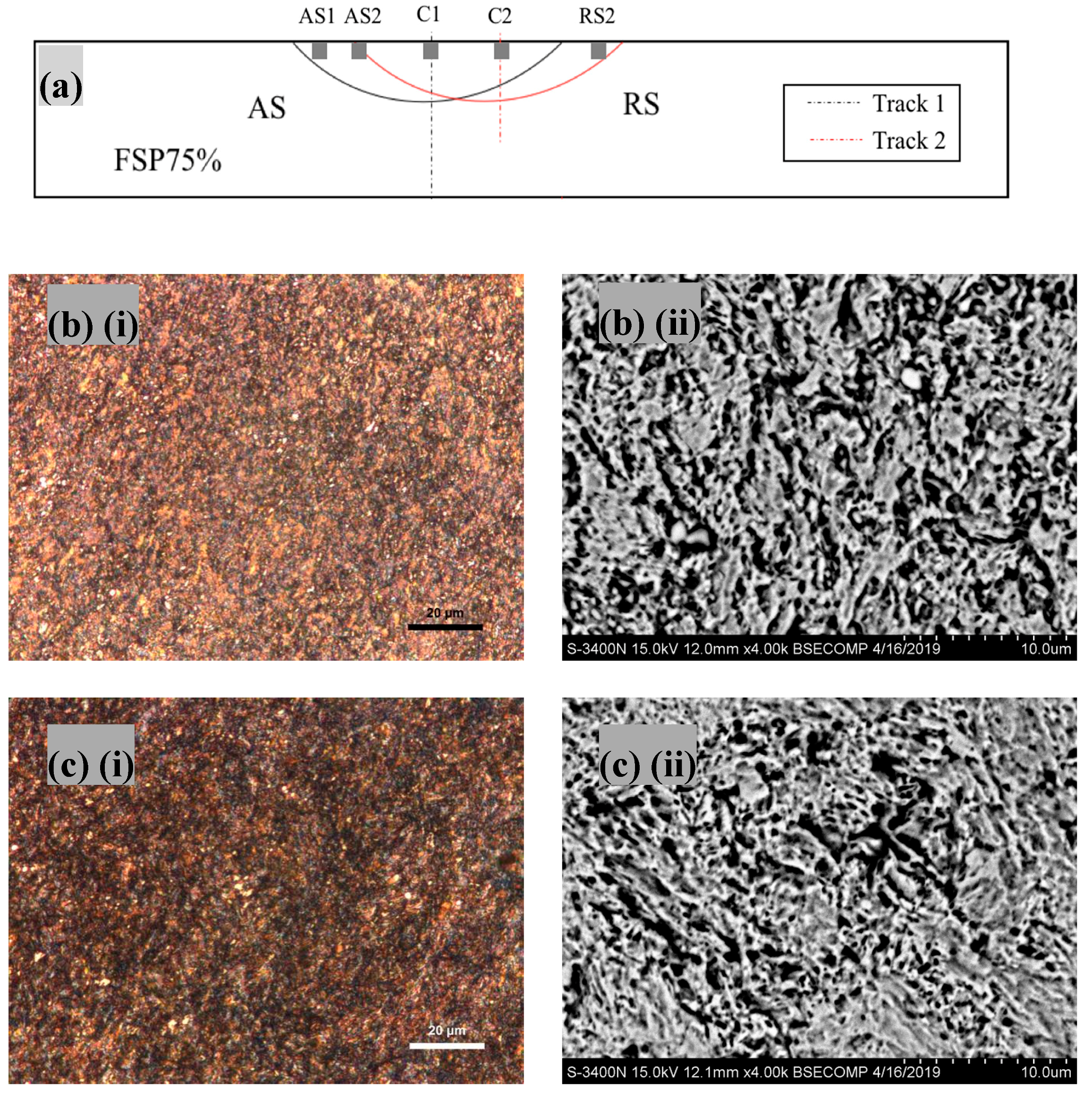
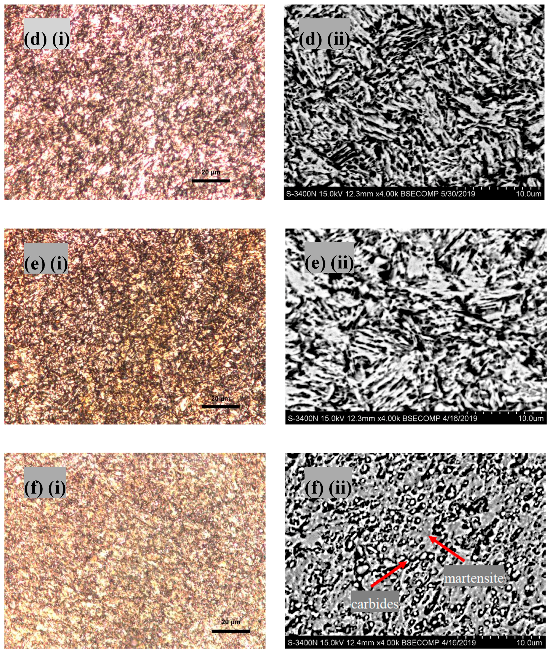
Microstructural analysis of the multi-pass FSPed specimen (FSP75%) was focused at four regions: AS1, AS2, C2, and RS2, as shown in Figure 5a. The microstructures of AS1, C2, and RS2 were very similar to the AS, C, and RS of the single-pass FSPed specimen (FSP250). AS1 and C2 mainly contained martensite and retained austenite, while RS2 consisted of some undissolved carbides (M23C6). The brighter globular regions were presumed as carbides, and the darker regions were regarded as martensite as shown in Figure 5f(ii). In particular, AS2 contained tempered martensite, which showed the darkest contrast among the other three regions reflecting its lowest corrosion resistance (Figure 5c). As the second pass was applied on the first track during FSP, the subsequent heating cycle imposed on the quenched martensite led to the formation of tempered martensite at the red region, as shown in Figure 6 [28].
Figure 6 shows the schematic of back-tempering in multi-pass FSP. The thermal field generated by the heat-affected zone of track 2 interacted with the processed region of track 1 (martensite + retained austenite). As a result, the interacted region (tempered region) was transformed to tempered martensite. Giorleo et al. [29] reported this phenomenon as back-tempering, which leads to a reduction in hardness [30].
Through austenitizing and rapid cooling, the martensite formed in AISI 420 is supersaturated with carbon and has a high dislocation density [10]. As the tempering temperature increases, the carbon from interstitial sites diffuses out of the martensite during tempering (Figure 7), which leads to the reduction of tetragonality of martensite and formation of chromium carbides, i.e., forming the tempered martensite [31]. After tempering, the martensite becomes cubic ferrite as the carbon atoms leave. In addition, the loss of carbon would induce a reduction in hardness [32]. In the tempered region (AS2) of the multi-pass FSPed specimens, precipitation of chromium carbides occurs at prior austenitic grain boundaries and also at the martensitic lath boundaries [31]. Chromium will deplete at the interface of the carbide and the surrounding metal matrix. Tempering is a diffusion-controlled phase transformation from a quenched martensite to a tempered martensitic structure containing ferrite and carbides. The precipitation and growth of carbides are strongly related to both tempering time and temperature [33]. As the tempering time was very short during FSP, the chromium carbides could not be clearly observed in Figure 5c due to their presumed nano size. Similar observations were reported by Hufenbach and his co-workers, who found that the size of precipitated carbides in the high-strength FeCrMoVC was in the range of 60 to 100 nm after short-term tempering [32]. In addition, Abbasi-Khazaei and Mollaahmadi [34] also observed fine carbides (<200 nm) in the reheated AISI 420 (700 °C for 2 min) using TEM.
For the heat-treatable steels, however, the drawback of overlapping is back-tempering of the hardened regions leading to non-uniform hardness distribution [30]. According to Mahmoudi’s work [13], multi-pass treating led to tempering the phases in the overlapped zones. For AISI 420, the range of tempering temperature is from 205 to 370 °C [35]. After tempering, the metastable quenched martensite and retained austenite will transform to ferrite and chromium carbides, which are the stable forms. Tempering causes the precipitation of chromium carbides at the grain boundaries of the ferritic phases, which may be harmful to the corrosion resistance of the multi-pass FSPed samples.
3.2. Hardness
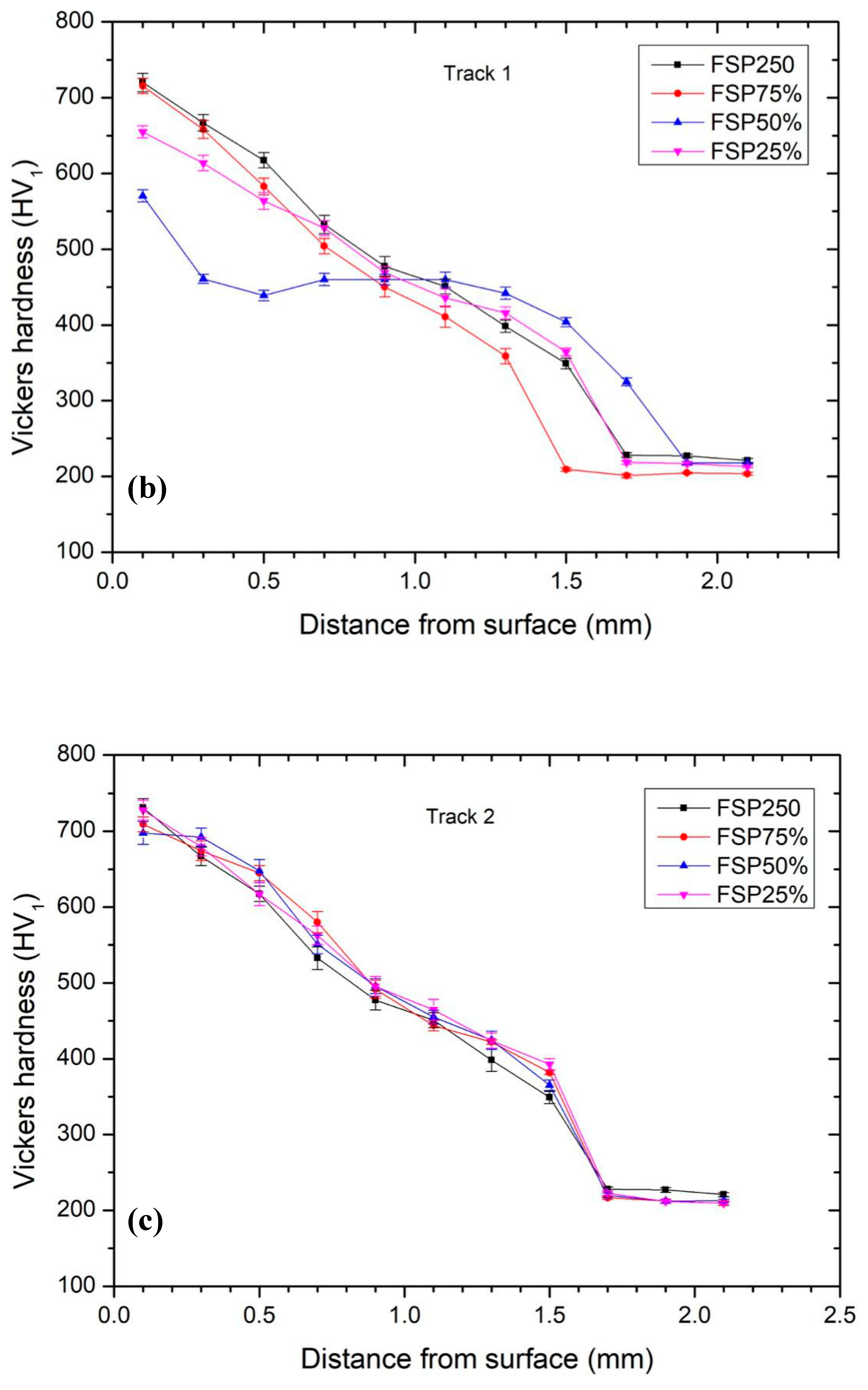
Figure 8 shows the hardness profiles along the centerlines of the first track (C1) and the second track (C2). It is observed that there was a decreasing trend of the hardness along the centerlines until it reached the hardness of the substrate (i.e., AR420: 184 HV1). This was due to the generation and transfer of frictional heat along the depth, affecting the effective transformation of martensite. In addition, in the single-pass FSPed specimen (FSP250), the hardness was about 720 HV1 at a depth of 0.1 mm beneath the surface and substantially higher than that of AQ420 (631 HV1) due to grain refinement and severe plastic deformation.
From Figure 8b, FSP50% (at C1) had a very distinct trend as compared to the other three profiles. The hardness decreased from the surface (570 HV1) to a depth of 0.5 mm; then, the hardness became constant (440 HV1) until the depth reached 1.5 mm. At last, the hardness gradually decreased along the depth until it reached the hardness of the substrate. The surface hardness for FSP50% (570 HV1) was lower than that of the single-pass FSPed specimen (720 HV1) by 21%. The lower hardness detected at C1 of FSP50% was due to back-tempering. The hypothesis behind the occurrence of softening was probably due to the diffusion of carbon atoms, reduction of dislocation density, and the martensite becoming less tetragonal [36]. From Figure 8c, the hardness profiles along C2 for the three multi-pass FSPed specimens demonstrated similar profiles (with surface hardness of 705–720 HV1) to that of the single-pass FSPed specimens (at C2) because the microstructure at C2 consisted of mainly martensite (Figure 5e).
The hardness profiles at 0.2 mm below the top surface in the longitudinal direction with different overlapping ratios are shown in Figure 9. The distribution of hardness of the single-pass FSP250 was not uniform in the longitudinal direction and decreased dramatically in the RS (Figure 9a), indicating the asymmetric distribution of the microstructure due to the difference in generated heat at AS and RS [18]. The heat generation was inadequate for complete martensitic transformation in RS. From Figure 9b–d, there was a dramatic drop in hardness near the intersection of the two tracks (i.e., near the AS2 of track 2). This was due to back-tempering [29], which caused a reduction in hardness at the tempered region. The Hollomon–Jaffe parameter (Hp) describes the effect of a heat treatment at a temperature for a certain time [37]. Specifically, it is used to describe the tempering of steels, and it is also called the “tempering parameter”.
where Hp is correlated to hardness, T is the temperature, and t is the time. C is a constant and varies with composition. From Equation (2), the same effect can be achieved with a low temperature and a long holding time, or with a higher temperature and a short holding time. During FSP, the holding time is very short; thus, the high temperature is the dominant factor for tempering. Although the reheating time was just a few seconds, it induced approximately 20% reduction in hardness, due to high temperature. Consequently, this phenomenon would lead to non-uniformity in surface hardness and deterioration of wear resistance [30].
3.3. Electrochemical Behavior
Figure 10 shows the potentiodynamic polarization curves of AR420, AQ420, and the single-pass and multi-pass FSPed specimens in 3.5 wt.% NaCl solution (open to air) at 25 °C. In the passive regions of potentiodynamic polarization curves, metastable corrosion activities occurred [38]. This indicates that the nucleation and propagation of pits happened before the onset of stable pitting [39]. As it was below the pitting potential, the metastable pits then repassivated. The free corrosion potential (Ecorr) and pitting potential (Epit) are summarized in Table 2. From Figure 10a and Table 2, the free corrosion potential (Ecorr = −141 mVSCE) and pitting potential (Epit = +4 mVSCE) of AR420 were more active than those of AQ420 and FSP250 because there were large amounts of carbide particles dispersed in the ferritic matrix. The corrosion behavior of AISI 420 in the chloride solution mainly depends on the amount of passivating element (Cr) in the solid solution [13]. The carbides are rich in Cr, leading to a decrease in Cr content in the nearby regions. Therefore, the Cr depletion regions acted as the anodic nucleation sites for pitting corrosion in the chloride medium [40]. From Table 2, the Epit of AQ420 (Epit = +154 mVSCE) was higher than that of AR420 because of the dramatic drop in carbide content in the martensite matrix after water quenching. This led to more Cr dissolved in the matrix, and the microstructure became more homogenous [10]. On the other hand, the highest Epit of FSP250 was due to the presence of martensite/austenite and the removal or refinement of M23C6.
From Figure 10b, no significant passivity could be observed for the multi-pass FSPed specimens, reflecting their low pitting corrosion resistance. In addition, the Icorr for the multi-pass FSPed specimens increased sharply and was higher than that of AQ420. It is noticed that the increase in Icorr could be attributed to the chromium carbide precipitation in narrow tempered regions, which acted as the anodic sites with small areas for corrosion, while the other regions with large areas were cathodic. Candelária and Pinedo [41] reported that the corrosion resistance of MSSs is highly sensitive to thermal tempering. According to the study of Abbasi-Khazaei and Mollaahmadi [35], the corrosion rate increases sharply at the reheating temperature of 700 °C due to the precipitated carbides.
The pit morphologies of AQ420 and FSP250 after polarization in 3.5 wt.% NaCl solution at 25 °C were reported in a previous study of the present authors [18]. Pits with a size of 100 μm were found to be dispersed uniformly on its surface. On the other hand, it was reported that the round pits with a diameter of 90 μm were concentrated on the RS of the FSP250. This is because there was more Cr tied up in the undissolved carbides at the RS where it was more anodic and selectively attacked [42]. The typical pit morphology of the multi-pass specimens was quite different from that of FSP250, as shown in Figure 11. The pits only gathered at the overlapped (back-tempered) regions (i.e., AS2 of track 2) in all specimens. Deep pits with big mouths were observed along the line of the tempered region. Pantelis et al. [43] studied the corrosion behavior of laser-surface hardened structural steel. They found that a higher overlapping ratio led to a high proportion of tempered martensite possessing lower corrosion resistance. This is due to the precipitation and inhomogeneous distribution of carbide in the low-carbon martensite [44]. According to the investigation of rapid tempering of AISI 420 by Abbasi-Khazaei and Mollaahmadi, the formation of chromium carbides during tempering is harmful to its corrosion resistance [34]. The matrix surrounded by the precipitated carbides was depleted in Cr and became the initiation sites for pitting attack. Consequently, less defective passive films were formed. Multi-pass FSPed 420 was susceptible to selective corrosion and caused a reduction in the hardness owing to the precipitation of chromium carbides at tempered regions.
4. Conclusions
From this study, the several conclusions can be drawn.
Similar to single-pass FSPed 420, the multi-pass FSPed specimens with different overlapping ratios incurred microstructural change at the center and retreating side of the second track with martensite, retained austenite, and chromium carbides.
Overlapping of the two successive tracks (multi-pass) in FSPed 420 led to back-tempering and local reduction in hardness near the advancing side of the second track.
Compared with the single-pass FSPed specimen (FSP250), much higher corrosion current densities were observed for the multi-pass FSPed specimens. This could be attributed to the precipitation of chromium carbides near the advancing side of the second track.
The degree of overlapping of the FSPed tracks affects the position of the back-tempered region with lower hardness and lower pitting corrosion resistance.
Author Contributions
Conceptualization, C.T.K., K.H.L.; Formal analysis, L.P.; Funding acquisition, C.T.K.; Investigation, L.P.; Supervision, C.T.K., K.H.L.; Writing–original draft, L.P.; Writing–review & editing, C.T.K., K.H.L.
Funding
The present work was fully supported by the Multi-Year Research Grant (MYRG) of University of Macau (Grant number MYRG2018-00217-FST).
Conflicts of Interest
The authors declare no conflict of interest.
References
- Thomas, W.M.; Nicholas, E.D.; Needham, J.C.; Murch, M.G.; Templesmith, P.; Dawes, C.J. Friction Stir Butt Welding. International Patent PCT/GB92/02203, GB Patent 9125978, December 1991. [Google Scholar]
- Mishra, R.S.; Ma, Z.Y. Friction stir welding and processing. Mater. Sci. Eng. R Rep. 2005, 50, 1–78. [Google Scholar] [CrossRef]
- Mishra, R.S.; Mahoney, M.W.; McFadden, S.X.; Mara, N.A.; Mukherjee, A.K. High strain rate superplasticity in a friction stir processed 7075 Al alloy. Scr. Mater. 1999, 42, 163–168. [Google Scholar] [CrossRef]
- Mironov, S.; Sato, Y.S.; Kokawa, H. Microstructural evolution during friction stir-processing of pure iron. Acta Mater. 2008, 56, 2602–2614. [Google Scholar] [CrossRef]
- Chainarong, S.; Muangjunburee, P.; Suthummanon, S. Friction Stir Processing of SSM356 Aluminium Alloy. Procedia Eng. 2014, 97, 732–740. [Google Scholar] [CrossRef] [Green Version]
- Morisada, Y.; Fujii, H.; Nagaoka, T.; Fukusumi, M. Nanocrystallized magnesium alloy—Uniform dispersion of C60 molecules. Scr. Mater. 2006, 55, 1067–1070. [Google Scholar] [CrossRef]
- Berbon, P.B.; Bingel, W.H.; Mishra, R.S.; Bampton, C.C.; Mahoney, M.W. Friction stir processing: A tool to homogenize nanocomposite aluminum alloys. Scr. Mater. 2001, 44, 61–66. [Google Scholar] [CrossRef]
- Grewal, H.S.; Arora, H.S.; Singh, H.; Agrawal, A. Surface modification of hydroturbine steel using friction stir processing. Appl. Surf. Sci. 2013, 268, 547–555. [Google Scholar] [CrossRef]
- Ni, D.R.; Xue, P.; Ma, Z.Y. Effect of Multiple-Pass Friction Stir Processing Overlapping on Microstructure and Mechanical Properties of As-Cast NiAl Bronze. Metall. Mater. Trans. A 2011, 42, 2125–2135. [Google Scholar] [CrossRef]
- Isfahany, A.N.; Saghafian, H.; Borhani, G. The effect of heat treatment on mechanical properties and corrosion behavior of AISI420 martensitic stainless steel. J. Alloy. Compd. 2011, 509, 3931–3936. [Google Scholar] [CrossRef]
- Gholi, A.R.; Lindwall, G.; Jönsson, M. Effects of tempering on corrosion properties of high nitrogen alloyed tooling steels in pyrolysis oil. Corros. Sci. 2011, 318, 1298. [Google Scholar]
- Dossett, J.L.; Totten, G.E.; ASM Handbook Committee. ASM Handbook, Volume 4A: Steel Heat Treating Fundamentals and Processes; ASM International: Almere, The Netherlands, 2013. [Google Scholar]
- Mahmoudi, B.; Torkamany, M.J.; Aghdam, A.S.R.; Sabbaghzade, J. Laser surface hardening of AISI 420 stainless steel treated by pulsed Nd:YAG laser. Mater. Des. (1980–2015) 2010, 31, 2553–2560. [Google Scholar] [CrossRef]
- Dodds, S.; Jones, A.H.; Cater, S. Tribological enhancement of AISI 420 martensitic stainless steel through friction-stir processing. Wear 2013, 302, 863–877. [Google Scholar] [CrossRef]
- Aldajah, S.H.; Ajayi, O.O.; Fenske, G.R.; David, S. Effect of friction stir processing on the tribological performance of high carbon steel. Wear 2009, 267, 350–355. [Google Scholar] [CrossRef]
- Puli, R.; Janaki Ram, G.D. Microstructures and properties of friction surfaced coatings in AISI 440C martensitic stainless steel. Surf. Coat. Technol. 2012, 207, 310–318. [Google Scholar] [CrossRef]
- Fattah-Alhosseini, A.; Attarzadeh, F.R.; Vakili-Azghandi, M. Effect of Multi-pass Friction Stir Processing on the Electrochemical and Corrosion Behavior of Pure Titanium in Strongly Acidic Solutions. Metall. Mater. Trans. A 2017, 48, 403–411. [Google Scholar] [CrossRef]
- Pan, L.; Kwok, C.T.; Lo, K.H. Enhancement in hardness and corrosion resistance of AISI 420 martensitic stainless steel via friction stir processing. Surf. Coat. Technol. 2019, 357, 339–347. [Google Scholar] [CrossRef]
- Leal, R.M.; Loureiro, A. Effect of overlapping friction stir welding passes in the quality of welds of aluminium alloys. Mater. Des. 2008, 29, 982–991. [Google Scholar] [CrossRef]
- Van Ingelgem, Y.; Vandendael, I.; Van den Broek, D.; Hubin, A.; Vereecken, J. Influence of laser surface hardening on the corrosion resistance of martensitic stainless steel. Electrochim. Acta 2007, 52, 7796–7801. [Google Scholar] [CrossRef]
- Nascimento, F.; Santos, T.; Vilaça, P.; Miranda, R.M.; Quintino, L. Microstructural modification and ductility enhancement of surfaces modified by FSP in aluminium alloys. Mater. Sci. Eng. A 2009, 506, 16–22. [Google Scholar] [CrossRef]
- ASTM. ASTM Standard CE384-17. Standard Test Method for Microindentation Hardness of Materials; ASTM: West Conshohocken, PA, USA, 2017. [Google Scholar]
- ASTM. ASTM Standard G5-14. Standard Reference Test Method for Making Potentiodynamic Anodic Polarization Measurements; ASTM: West Conshohocken, PA, USA, 2014. [Google Scholar]
- Gandra, J.; Miranda, R.M.; Vilaça, P. Effect of overlapping direction in multipass friction stir processing. Mater. Sci. Eng. A 2011, 528, 5592–5599. [Google Scholar] [CrossRef]
- Avila, J.A.; Giorjao RA, R.; Rodriguez, J.; Fonseca, E.B.; Ramirez, A.J. Modeling of thermal cycles and microstructural analysis of pipeline steels processed by friction stir processing. Int. J. Adv. Manuf. Technol. 2018, 98, 2611–2618. [Google Scholar] [CrossRef] [Green Version]
- Hajian, M.; Abdollah-zadeh, A.; Rezaei-Nejad, S.S.; Assadi, H.; Hadavi, S.M.M.; Chung, K.; Shokouhimehr, M. Microstructure and mechanical properties of friction stir processed AISI 316L stainless steel. Mater. Des. 2015, 67, 82–94. [Google Scholar] [CrossRef]
- Baghjari, S.H.; Akbari Mousavi SA, A. Effects of pulsed Nd:YAG laser welding parameters and subsequent post-weld heat treatment on microstructure and hardness of AISI 420 stainless steel. Mater. Des. 2013, 43, 1–9. [Google Scholar] [CrossRef]
- Lakhkar, R.S.; Shin, Y.C.; Krane, M.J.M. Predictive modeling of multi-track laser hardening of AISI 4140 steel. Mater. Sci. Eng. A 2008, 480, 209–217. [Google Scholar] [CrossRef]
- Giorleo, L.; Previtali, B.; Semeraro, Q. Modelling of back tempering in laser hardening. Int. J. Adv. Manuf. Technol. 2010, 54, 969–977. [Google Scholar] [CrossRef]
- Iino, Y.; Shimoda, K. Effect of overlap pass tempering on hardness and fatigue behaviour in laser heat treatment of carbon steel. J. Mater. Sci. Lett. 1987, 6, 1193–1194. [Google Scholar] [CrossRef]
- Sunil Kumar, B.; Kain, V.; Vishwanadh, B. Effect of Tempering Treatments on Microstructure and Intergranular Corrosion of 13 wt% Cr Martensitic Stainless Steel. Corrosion 2017, 73, 362–378. [Google Scholar] [CrossRef]
- Hufenbach, J.; Giebeler, L.; Hoffmann, M.; Kohlar, S.; Kühn, U.; Gemming, T.; Eckert, J. Effect of short-term tempering on microstructure and mechanical properties of high-strength FeCrMoVC. Acta Mater. 2012, 60, 4468–4476. [Google Scholar] [CrossRef]
- Santhanakrishnan, S.; Kong, F.; Kovacevic, R. An experimentally based thermo-kinetic phase transformation model for;multi-pass laser heat treatment by using high power direct diode laser. Int. J. Adv. Manuf. Technol. 2013, 64, 219–238. [Google Scholar] [CrossRef]
- Abbasi-Khazaei, B.; Mollaahmadi, A. Rapid Tempering of Martensitic Stainless Steel AISI420: Microstructure, Mechanical and Corrosion Properties. J. Mater. Eng. Perform. 2017, 26, 1626–1633. [Google Scholar] [CrossRef]
- Lippold, J.C.; Kotecki, D.J. Welding Metallurgy and Weldability of Stainless Steels; John Wiley and Sons Inc.: Hoboken, NJ, USA, 2005. [Google Scholar]
- Salih, A.A.; Omar, M.Z.; Junaidi, S.; Sajuri, Z. Effect of Different Heat Treatment on the SS440C Martensitic Stainless Steel. Aust. J. Basic Appl. Sci. 2011, 5, 867–871. [Google Scholar]
- Hollomon, J.H.; Jaffe, L.D. Time-temperature relations in tempering steel. Trans. AIME 1945, 162, 223–249. [Google Scholar]
- Anantha, K.H.; Örnek, C.; Ejnermark, S.; Medvedeva, A.; Sjöström, J.; Pan, J. Correlative Microstructure Analysis and In Situ Corrosion Study of AISI 420 Martensitic Stainless Steel for Plastic Molding Applications. J. Electrochem. Soc. 2017, 164, C85–C93. [Google Scholar] [CrossRef]
- Burstein, G.T.; Liu, C.; Souto, R.M.; Vines, S.P. Origins of pitting corrosion. Corros. Eng. Sci. Technol. 2004, 39, 25–30. [Google Scholar] [CrossRef]
- Baroux, B. Further insights on the pitting corrosion of stainless steels. Corros. Mech. Theory Pract. 1995, 265–310. [Google Scholar]
- Candelária, A.F.; Pinedo, C.E. Influence of the heat treatment on the corrosion resistance of the martensitic stainless steel type AISI 420. J. Mater. Sci. Lett. 2003, 22, 1151–1153. [Google Scholar] [CrossRef]
- Schneider, M.; Kremmer, K.; Lämmel, C.; Sempf, K.; Herrmann, M. Galvanic corrosion of metal/ceramic coupling. Corros. Sci. 2014, 80, 191–196. [Google Scholar] [CrossRef]
- Pantelis, D.I.; Bouyiouri, E.; Kouloumbi, N.; Vassiliou, P.; Koutsomichalis, A. Wear and corrosion resistance of laser surface hardened structural steel. Surf. Coat. Technol. 2002, 161, 125–134. [Google Scholar] [CrossRef]
- Malheiros LR, C.; Rodriguez EA, P.; Arlazarov, A. Mechanical behavior of tempered martensite: Characterization and modeling. Mater. Sci. Eng. A 2017, 706, 38–47. [Google Scholar] [CrossRef]
Figure 1.
(a) Schematic diagram and (b) overview of multi-pass overlapped tracks.

Figure 2.
Optical micrographs of the cross-sections of FSPed AISI 420 with various overlapping ratios: (a) FSP250; (b) FSP75%; (c) FSP50%; and (d) FSP25%.
Figure 2.
Optical micrographs of the cross-sections of FSPed AISI 420 with various overlapping ratios: (a) FSP250; (b) FSP75%; (c) FSP50%; and (d) FSP25%.

Figure 3.
SEM micrographs of single-pass friction stir processed (FSPed) 420 (FSP250): (a) advancing side (AS); (b) electron backscatter diffraction (EBSD) band contrast imposed by phase maps (the red phase is austenite) at the AS; (c) center (C); (d) retreating side (RS).
Figure 3.
SEM micrographs of single-pass friction stir processed (FSPed) 420 (FSP250): (a) advancing side (AS); (b) electron backscatter diffraction (EBSD) band contrast imposed by phase maps (the red phase is austenite) at the AS; (c) center (C); (d) retreating side (RS).

Figure 4.
X-ray diffraction (XRD) spectra of annealed 420 (AR420), conventional hardened 420 (AQ420), single-pass specimen (FSP250), and multi-pass specimens (at the middle of two overlapped tracks) fabricated at different overlapping ratios.
Figure 4.
X-ray diffraction (XRD) spectra of annealed 420 (AR420), conventional hardened 420 (AQ420), single-pass specimen (FSP250), and multi-pass specimens (at the middle of two overlapped tracks) fabricated at different overlapping ratios.
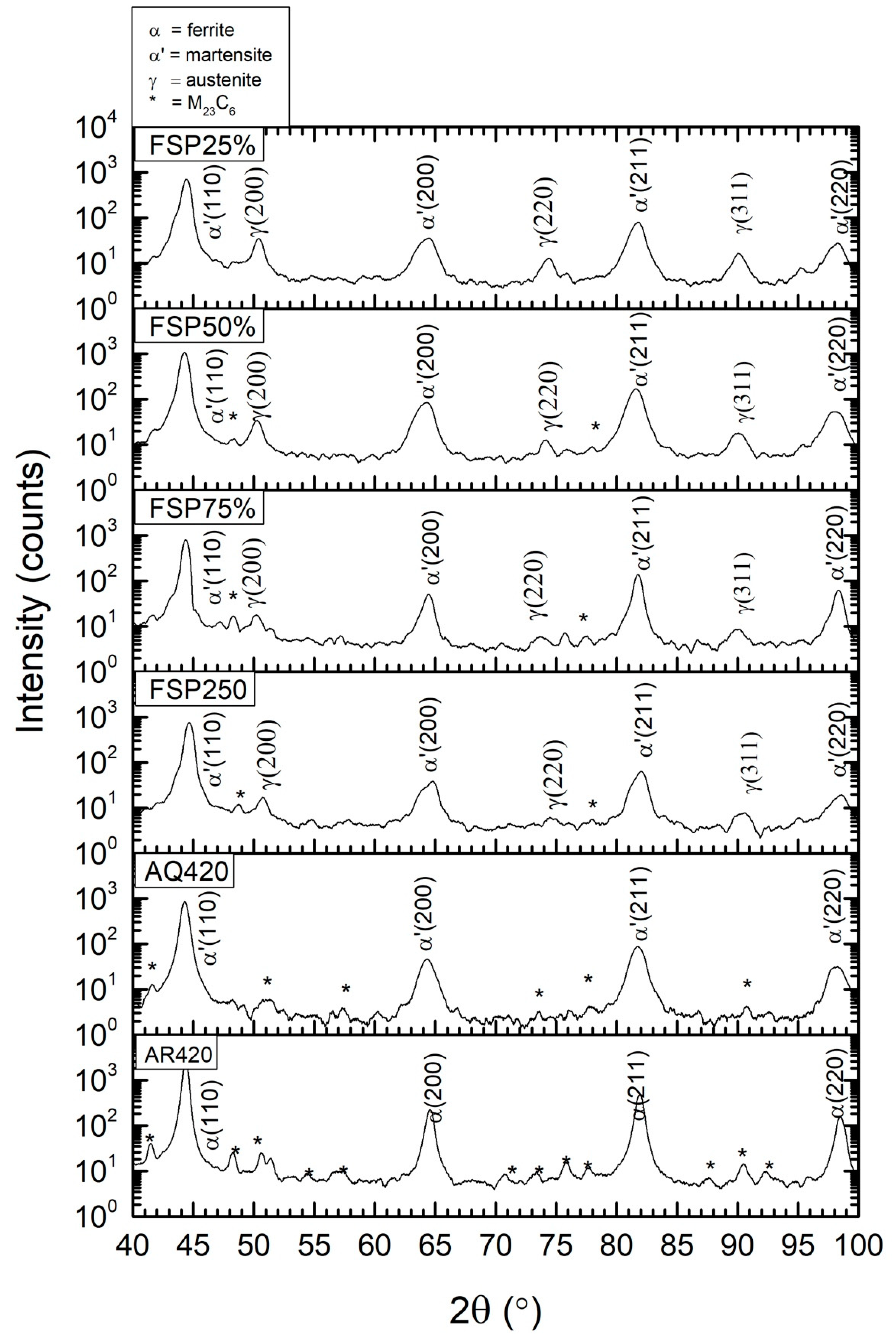
Figure 5.
(a) Schematic diagram of cross-section of FSP75%; microstructures of (b) AS1, (c) AS2, (d) C1, (e) C2, and (f) RS2: (i) optical microscope (OM) and (ii) SEM micrographs.
Figure 5.
(a) Schematic diagram of cross-section of FSP75%; microstructures of (b) AS1, (c) AS2, (d) C1, (e) C2, and (f) RS2: (i) optical microscope (OM) and (ii) SEM micrographs.


Figure 6.
Schematic of back-tempering in the multi-pass FSPed 420.

Figure 7.
Schematic of changes in crystal structure of martensite during tempering (BCT: body-centered tetragonal; BCC: body-centered cubic).
Figure 7.
Schematic of changes in crystal structure of martensite during tempering (BCT: body-centered tetragonal; BCC: body-centered cubic).

Figure 8.
(a) Illustration showing the overlapping of track 1 and track 2; the hardness profiles of FSPed specimens along the centerline of (b) track 1 (C1) and (c) track 2 (C2).
Figure 8.
(a) Illustration showing the overlapping of track 1 and track 2; the hardness profiles of FSPed specimens along the centerline of (b) track 1 (C1) and (c) track 2 (C2).


Figure 9.
Hardness profiles of FSPed specimens at 0.2 mm below the surface in the longitudinal direction: (a) FSP250, (b) FSP75%, (c) FSP50%, and (d) FSP25%.
Figure 9.
Hardness profiles of FSPed specimens at 0.2 mm below the surface in the longitudinal direction: (a) FSP250, (b) FSP75%, (c) FSP50%, and (d) FSP25%.
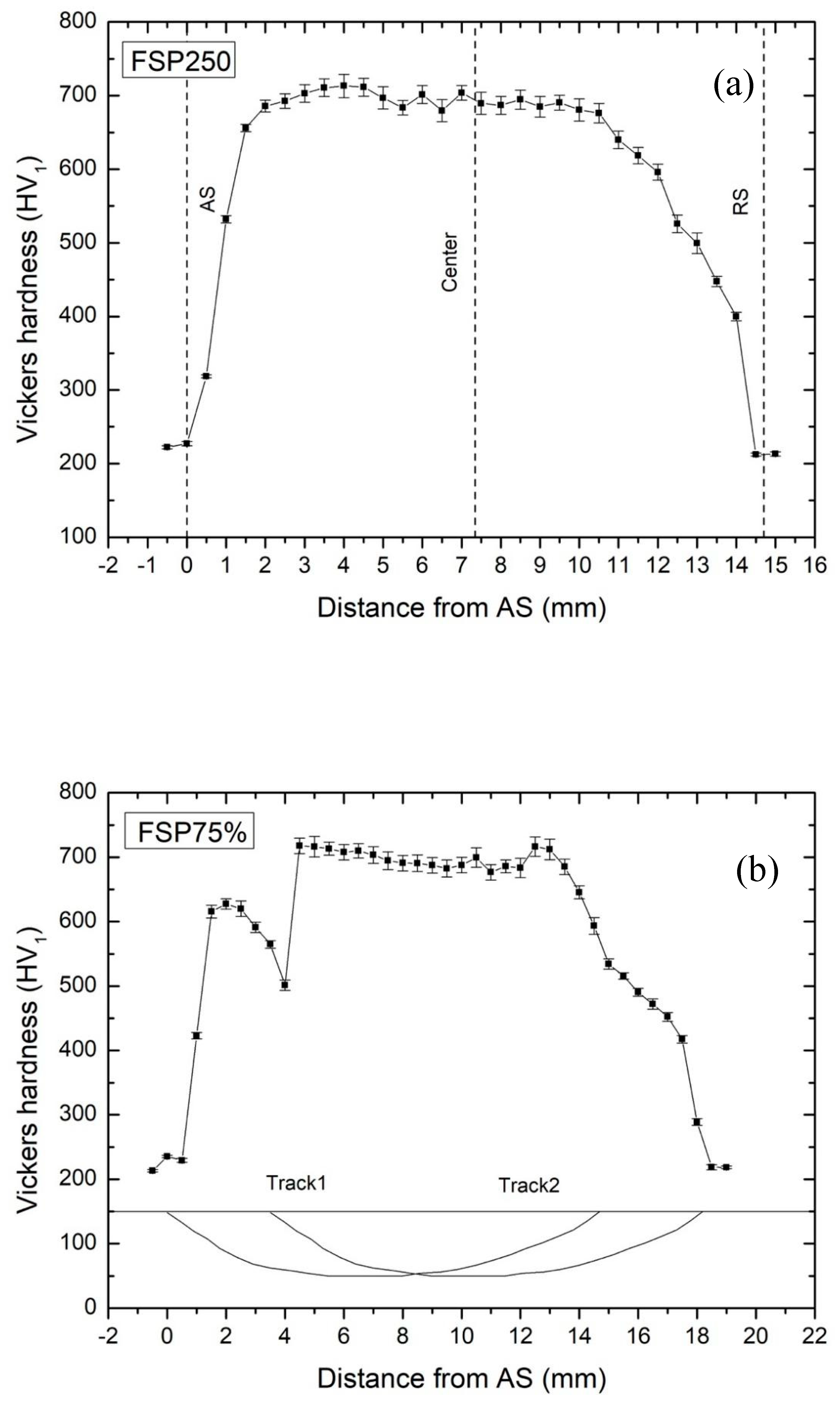
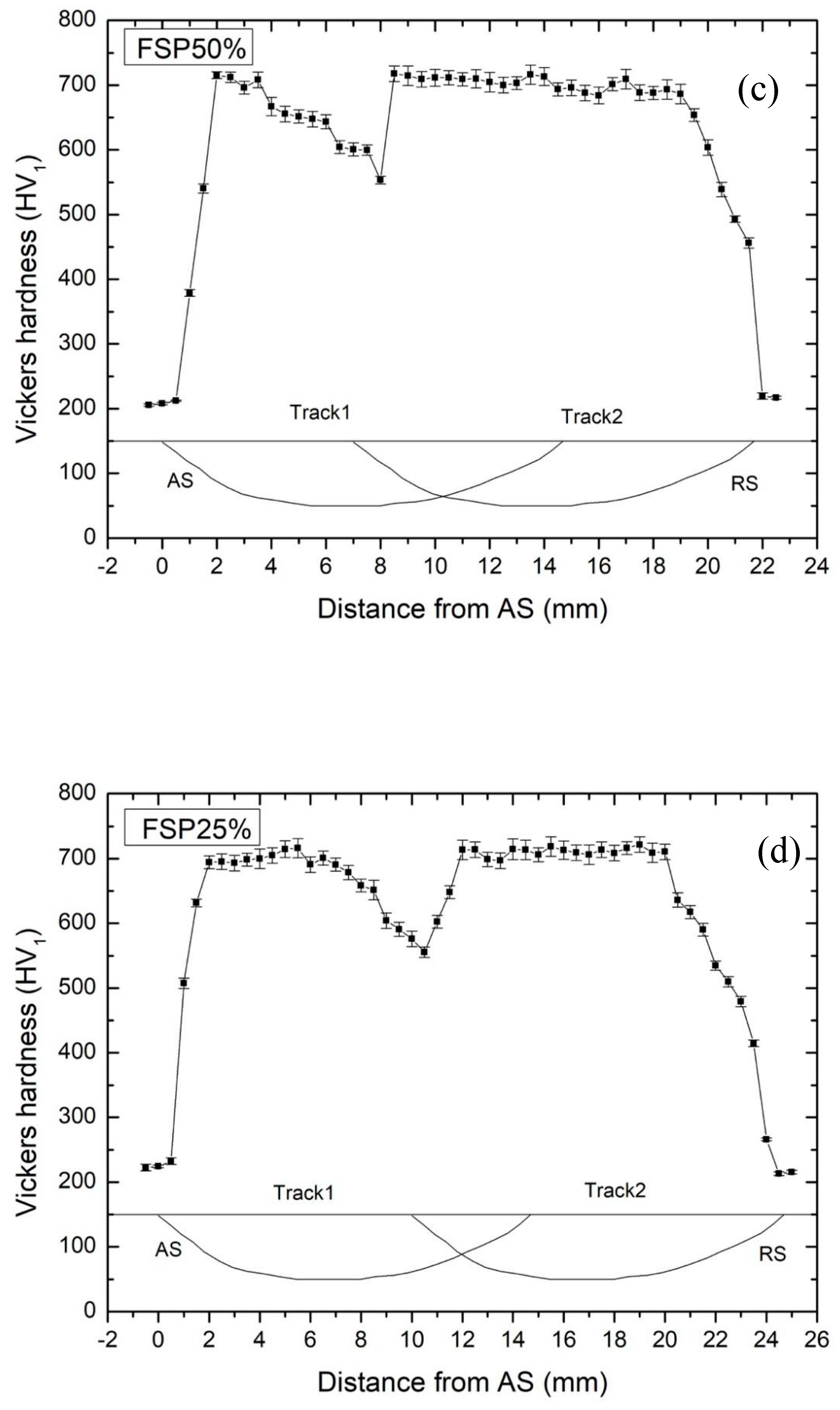
Figure 10.
Potentiodynamic polarization curves of (a) as-received 420, as-quenched 420, and FSP250 [18]; (b) FSP75%, FSP50%, FSP25%, and AQ420 in 3.5% NaCl solution at 25 °C.
Figure 10.
Potentiodynamic polarization curves of (a) as-received 420, as-quenched 420, and FSP250 [18]; (b) FSP75%, FSP50%, FSP25%, and AQ420 in 3.5% NaCl solution at 25 °C.

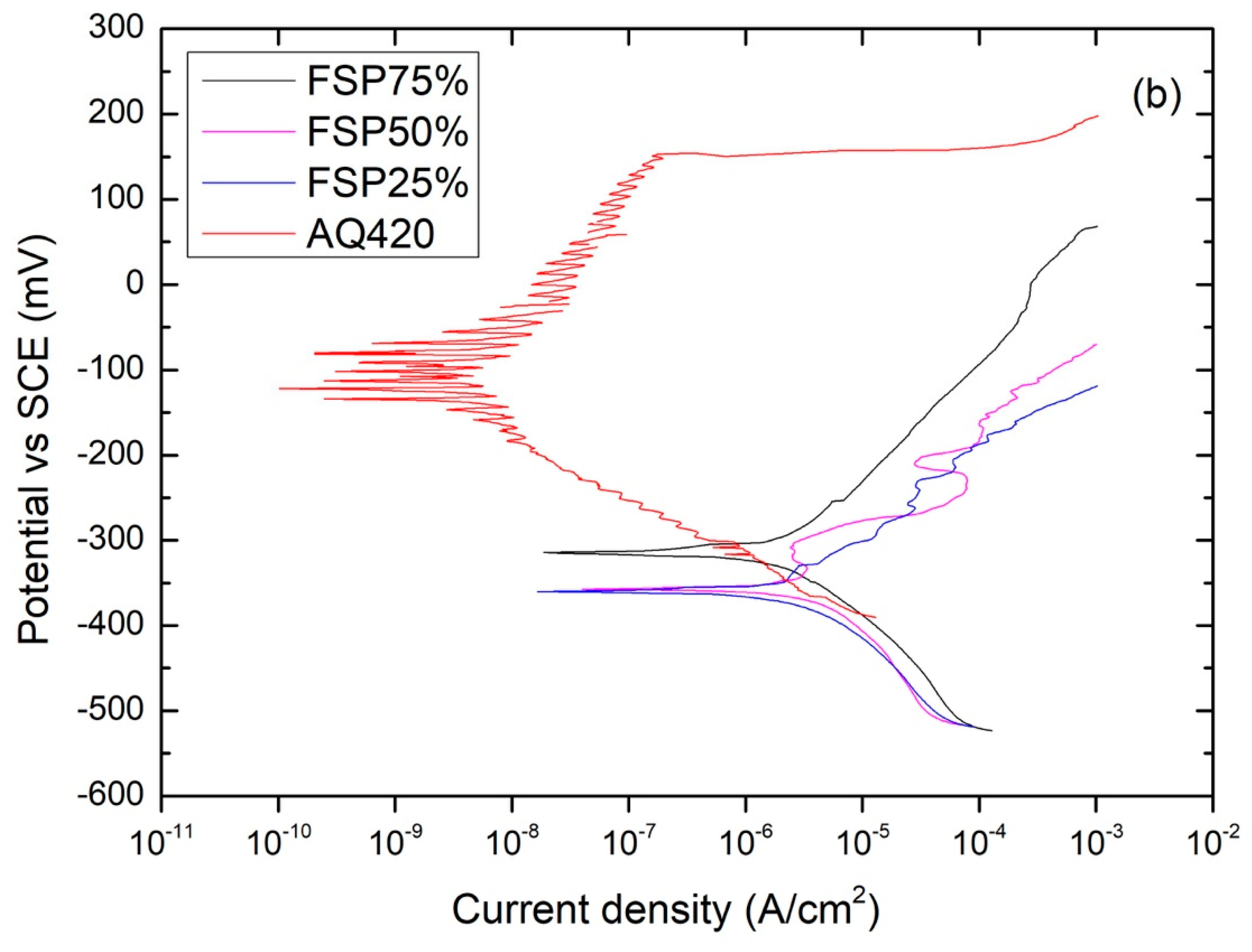
Figure 11.
Corrosion morphology of FSP75% after polarization test.


Table 1.
Nominal chemical compositions of AISI 420 (wt.%).
| Material | C | Cr | Si | Mn | Fe |
|---|---|---|---|---|---|
| AISI 420 | 0.30 ± 0.05 | 15.4 ± 0.26 | 0.50 ± 0.07 | 0.45 ± 0.12 | Balance |
Table 2.
Corrosion parameters of various specimens. SCE—saturated calomel electrode; AR420—annealed 420; AQ420—conventional hardened 420; FSP—friction stir processing.
Table 2.
Corrosion parameters of various specimens. SCE—saturated calomel electrode; AR420—annealed 420; AQ420—conventional hardened 420; FSP—friction stir processing.
| Specimen | Ecorr (mV) vs. SCE | Epit (mV) vs. SCE |
|---|---|---|
| AR420 | −141 ± 8 | 4.0 ± 6 |
| AQ420 | −92 ± 4 | 154 ± 7 |
| FSP250 | −55 ± 10 | 161 ± 23 |
| FSP75% | −314 ± 17 | active |
| FSP50% | −357 ± 15 | active |
| FSP25% | −360 ± 17 | active |
© 2019 by the authors. Licensee MDPI, Basel, Switzerland. This article is an open access article distributed under the terms and conditions of the Creative Commons Attribution (CC BY) license (http://creativecommons.org/licenses/by/4.0/).
Share and Cite
MDPI and ACS Style
Pan, L.; Kwok, C.T.; Lo, K.H. Effect of Multiple-Pass Friction Stir Processing on Hardness and Corrosion Resistance of Martensitic Stainless Steel. Coatings 2019, 9, 620. https://doi.org/10.3390/coatings9100620
AMA Style
Pan L, Kwok CT, Lo KH. Effect of Multiple-Pass Friction Stir Processing on Hardness and Corrosion Resistance of Martensitic Stainless Steel. Coatings. 2019; 9(10):620. https://doi.org/10.3390/coatings9100620
Chicago/Turabian StylePan, Linlin, Chi Tat Kwok, and Kin Ho Lo. 2019. "Effect of Multiple-Pass Friction Stir Processing on Hardness and Corrosion Resistance of Martensitic Stainless Steel" Coatings 9, no. 10: 620. https://doi.org/10.3390/coatings9100620
Note that from the first issue of 2016, this journal uses article numbers instead of page numbers. See further details here.