
Enhancing Fault Awareness and Reliability of a Fault-Tolerant RISC-V System-on-Chip


1
LIRMM, University of Montpellier, CNRS, 34095 Montpellier, France
2
IES, University of Montpellier, CNRS, 34095 Montpellier, France
3
LEDS, University of Vale do Itajaí, Itajaí 88302-901, Brazil
*
Author to whom correspondence should be addressed.
Electronics 2023, 12(12), 2557; https://doi.org/10.3390/electronics12122557
Submission received: 21 April 2023
/
Revised: 25 May 2023
/
Accepted: 31 May 2023
/
Published: 6 June 2023
(This article belongs to the Special Issue Radiation Tolerant Electronics, Volume III)
Abstract
:Recent research has shown interest in adopting the RISC-V processors for high-reliability electronics, such as aerospace applications. The openness of this architecture enables the implementation and customization of the processor features to increase their reliability. Studies on hardened RISC-V processors facing harsh radiation environments apply fault tolerance techniques in the processor core and peripherals, exploiting system redundancies. In prior work, we present a hardened RISC-V System-on-Chip (SoC), which could detect and correct radiation-induced faults with limited fault awareness. Therefore, in this work, we propose solutions to extend the fault observability of the SoC implementation by providing error detection and monitoring. For this purpose, we introduce observation features in the redundant structures of the system, enabling the report of valuable information that supports enhanced radiation testing and support the application to perform actions to recover from critical failures. Thus, the main contribution of this work is a solution to improve fault awareness and the analysis of the fault models in the system. In order to validate this solution, we performed complementary experiments in two irradiation facilities, comprehending atmospheric neutrons and a mixed-field environment, in which the system proved to be valuable for analyzing the radiation effects on the processor core and its peripherals. In these experiments, we were able to obtain a range of error reports that allowed us to gain a deeper understanding of the faults mechanisms, as well as improve the characterization of the SoC.
Keywords:
RISC-V; System-on-Chip; dependability; radiation effects; radiation testing; neutrons; mixed-field1. Introduction
The increasing dependence on electronic systems developing complex and critical tasks in modern technologies creates several challenges related to reliability requirements. Many systems are based on powerful processing units that must be fail-safe and guarantee continuous service delivery. Each application sector must comply with standards and guidelines to meet such requirements as seen in the automotive [1], aerospace [2,3], and military [4] industries. With the introduction of the RISC-V architecture, several projects and research efforts were initiated to adopt these novel RISC-based processors in many application domains. In particular, the open and modular nature of the architecture provided traction for its adoption in high reliability and critical systems [5].
Within these application domains, several reliability requirements are derived from the environmental conditions, in which these systems are exposed: temperature variations, pressure profile, mechanical stress, and ionizing radiation. For avionics flying in high altitudes or in orbit, ionizing radiation seriously threatens the dependable operation of such systems [6,7]. The interaction of ionizing particles with electronic devices generates a plethora of effects. Single-Event Effects (SEEs) are an important phenomena, which induce transient, intermittent, and permanent faulty behaviors [8]. For processors, these effects can be observed as corrupted bits, wrong calculations, and transients, which may result in application output error, data corruption, unexpected termination, and hangs [9].
In order to ensure the dependability of these processing systems, several fault tolerance techniques are applied to the processors’ architecture and the surrounding peripherals. These techniques exploit temporal, spatial, and informational redundancies [10]. Recent work explored and analyzed the effectiveness of these techniques applied to the RISC-V architecture with fault injection campaigns, implemented as soft-core modules inside Field-Programmable Gate Array (FPGA) devices. In [11,12], the authors explore different approaches for improving the architectural elements of the processor. In [13,14], RISC-V cores with Triple Modular Redundancy (TMR) were implemented and validated, achieving significant reliability improvements but with a high resource utilization penalty. As seen in [15], the design of a lockstep RISC-V was proposed to address safety-critical applications. Other works presented hybrid solutions with similar strategies to find an optimal trade-off between performance, resource utilization, and reliability, such as [16,17,18]. In prior work, we proposed a fault-tolerant implementation of a RISC-V system [19,20] designed for FPGAs, known as HARV-SoC, where hybrid architectural redundancy techniques were applied, compared, and evaluated.
These fault-tolerant designs are usually validated through fault injection campaigns, either with simulation environments, emulation strategies, software frameworks, or real stimuli (e.g., exposition to radiation in particle accelerators). All those strategies offer valuable data to enable the reliability assessment of complex systems [9,21]. For application domains with demanding dependable systems (i.e., aerospace, military), performing fault injection campaigns with real stimuli is a mandatory step to meet standards criteria [3]. These campaigns are mostly adopted during the development and validation phases of new systems. For this, designers instrument their systems with observation points [20] and prepare meaningful benchmarks [22] to enable observation and measuring of the system’s fault sensitivity. However, most fault-tolerant RISC-V implementations explored in the literature focus mainly on tolerating faults, making in-depth reliability analysis complicated due to the lack of information. As a result, this approach leads to a limited understanding of these complex systems in harsh radiation environments. However, implementing observation structures is a challenging task, given that hard-core processors do not have customization capabilities, and soft-core processors in FPGAs require additional configuration structures that are also susceptible to failures.
In this work, we propose a strategy targeting enhanced error tracking in the HARV-SoC by extending the fault observability of the SoC implementation through runtime error detection. For this purpose, we monitor critical structures of the SoC architecture to report relevant information about the errors triggered by radiation-induced events. This solution allows a better understanding of the underlying impacts of SEEs in the design compared to alternative strategies. Furthermore, it enables more efficient use of the hardening countermeasures and provides the means for the application to perform actions to recover in case of critical failures. To implement and validate the concept, we instrument the HARV-SoC with this solution and evaluate the observability effectiveness through neutron and mixed-field irradiation campaigns. It is worth mentioning that this solution presented many technical challenges since many internal structures had to be prepared for this purpose. Furthermore, prior field expertise was important in guiding the definition of the information to be monitored and reported in an effective manner.
The remaining of the paper is structured as follows: Section 2 presents the related work; Section 3 describes key aspects of our RISC-V implementation and its fault tolerance and awareness features; Section 4 presents the proposed experimental strategy; Section 5 presents the results and analysis; Section 6 discusses these results and outcomes; and Section 7 concludes the work.
2. Related Work
Recent studies explored fault tolerance techniques to improve the reliability of RISC-V systems but provided a superficial analysis of the reported errors. Table 1 presents and compares the different approaches for the detection and observation of errors found for RISC-V systems in the literature. We grouped the works using horizontal lines in the table based on their fault injection strategy: simulation, emulation, or radiation, respectively. Moreover, six categories were defined for comparison: 1. core architecture, providing the used RISC-V core implementation; 2. hardening strategy, showing the different fault tolerance techniques applied; 3. configuration memory check, to evidence its impact in the injection campaign; 4. evaluation coverage, showing the observed elements; 5. output classification, to compare the provided execution classification; and 6. error analysis, in which the types of analyses are described.
For simulation-based validations [15], the authors perform initial validation of their systems and only provide functional analysis. This approach provides full information on internal components and faulty behavior but uses limited fault models. When emulation is used [11,12,23], authors often use dedicated components to inject and monitor errors in the configuration memory of the target FPGA. In some cases, more high-level techniques are employed to inject faults during the software execution [18]. Nevertheless, emulations are similar to simulations, in other words, they are as good as the used fault models are realistic, i.e., in correlation to the real phenomena generation the faults.
For injections using radiation experiments [13,14,17,20], authors attempt to provide a description of the observed errors and their possible impact on their systems. Then, the main goal is to assess and correlate the observed phenomena with known fault models and measure the sensitivity of the systems to the specific tested radiation source. Despite that, this approach is prone to limited availability of information, leading to conclusions with error rates uncorrelated with architectural elements or inconclusive behavioral trends.
Therefore, this work contributes with solutions that provide additional information during irradiation test campaigns. The proposed technique is capable of reporting the errors intervening in protected internal structures. Then, in a RISC-V implementation with the employment of hardening techniques in the entire SoC or in the critical elements, the main architecture-related errors can be reported. With the combination of multiple observation points and report generation in runtime, the experiment can be better monitored, allowing posterior enhanced analysis with coherent and resourceful execution logs. This supports the cross-analysis of the phenomena from different perspectives and increases the correlation between the observed hardware errors and software behavior. Notably, the experiments reported on [13,14,17] would greatly benefit from the observation strategy adopted in this work, since more valuable outcomes and conclusions could be reported, even enhancing the opportunities for architectural and hardening techniques comparisons.
3. Fault Tolerance and Awareness
In prior work, we introduced the processor core, which presented reliability improvements in its RISC-V organization [24]. Following that, we extended it to a System-on-Chip, containing a bus implementation with peripherals, whose reliability was also evaluated through simulations [19]. After that, we focused on the characterization and analysis of the SoC under neutron irradiation [20].
This work presents results from a new fault injection campaign with atmospheric neutron irradiation, detailing the improvements proposed for our fault-tolerant architecture at the processor and SoC levels.
3.1. RISC-V Processor Core
In previous test campaigns, we identified that error counters could quantify the number of radiation-induced faults detected by the implemented fault tolerance techniques. These techniques were TMR at the control and Arithmetic Logic Unit (ALU) and Error Correcting Code (ECC) with Single Error Correction and Double Error Detection (SECDED) in the processor core registers and the data memory. In this implementation, the errors were detected and corrected in the background, not affecting the application execution time.
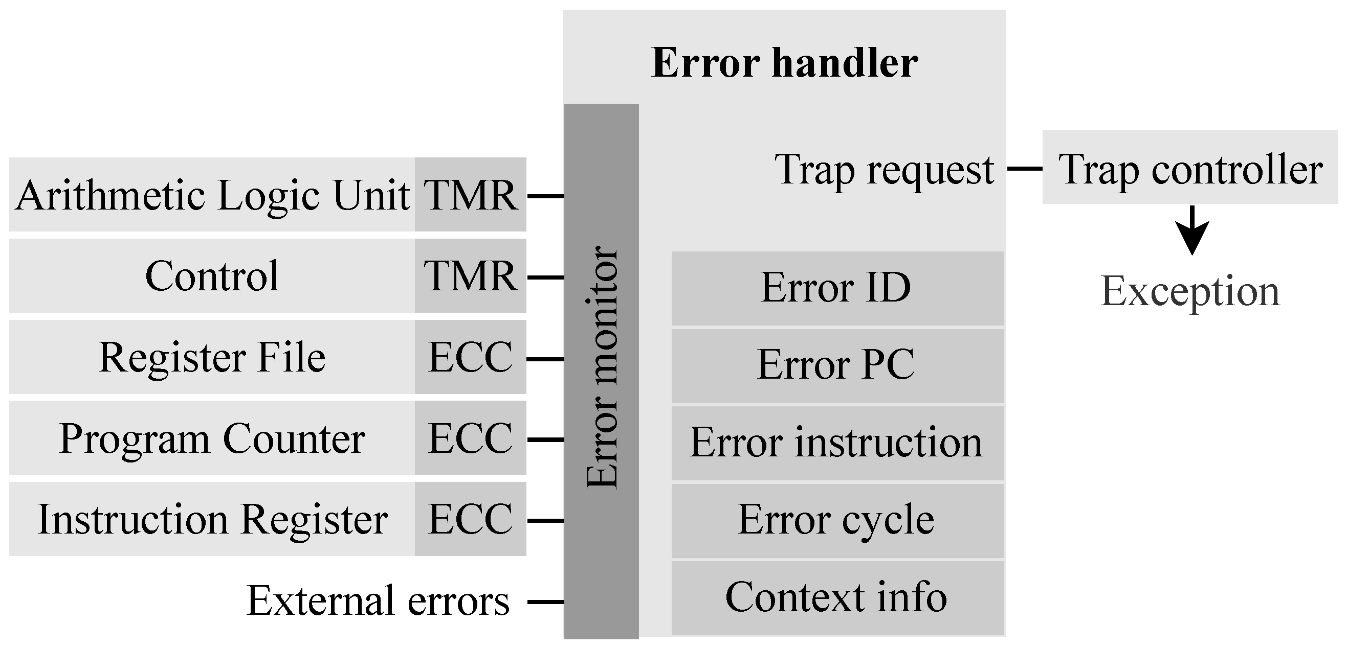
Although the error counting technique was effective, the information provided about each detected error was very scarce, comprising only the number of occurrences for each error, which was later reported by the application. Therefore, in this work, we propose a solution that makes use of more processor assets to provide further information in execution time. The solution consists of implementing an error handler component in the processor core that requests traps when errors are detected. It monitors the signals from the fault-tolerant structures, saving relevant information about the detected errors, as presented in Figure 1. The trap controller handles the request as an exception, ensuring that the processor will handle this error as soon as possible.
The detectable errors in the error handler include the following errors of the processor: Program Counter (PC) single- and double-bit upsets, Instruction Register (IR) single- and double-bit upsets, register file single- and double-bit upsets, control TMR error, and ALU TMR error. The detected errors are all reported through exceptions, regardless of their correctability. Besides reporting errors in the processor core, the error handler design also includes the external error input, which is available as a processor core input signal. The purpose of this signal is to enable the SoC to report errors in its structures, such as interconnections and peripherals.
The error handler has a set of registers that store information upon detecting an error. These registers are implemented in the error handler component and are mapped in the memory. This way, we save the data at the moment the error was detected and provide additional information regarding the error details. The basic error information comprises the error identifier, a register in which each bit corresponds to one type of error. The application must clear this register to indicate that the error has been handled, and the execution should continue. Further information that supports additional analysis of the error is provided such as the values from the ALU output, PC, IR, and cycle register. For bit-upset errors, the encoded data with the bit upset and its ECC are recorded. Besides that, the application context is provided. The error handler has a number of registers that store the PC whenever a function is called, which is cleared when it returns. This part is implemented by a rotating queue, which increments the queue pointer when a function is called and decrements it when it returns. With this information, it is possible to identify the context in which the error has occurred.
3.2. RISC-V System-on-Chip
The implementation of the error handler provides more details on the errors occurring in the RISC-V processor. However, errors are also prone to appear at the SoC level. For that, we improved the reliability of the SoC by adding additional logic to the bus master controller, which now has the ability to identify a timeout for bus accesses. Furthermore, we changed the memory, which was previously implemented with FPGA internal resources, to an external Synchronous Dynamic Random-Access Memory (SDRAM). This implementation enables more complex applications since the size of memory available increases significantly. We implement an exclusive error handler to provide observability at the SoC level, which requests traps to the error handler through the external error input.
This separation of core and SoC handlers simplified the design for the processor core error handler since it does not need to consider all different kinds of errors that may be implemented for different SoC designs. In addition, it provides more flexibility for the SoC error handler since designs may require more complex error handling. An overview of the HARV-SoC implementation is shown in Figure 2, in which the SoC error handler monitors errors from the bus master and the memory controller, signaling to the core when an error has occurred.
The following subsections describe the integration of an external SDRAM into the design, including its memory controller that adds error correction and detection capabilities, and the implementation of the SoC error handler, respectively.
3.2.1. SDRAM EDAC Controller
Neither the SDRAMs nor the standard SDRAM controllers provide Error Detection and Correction (EDAC) for the stored values. Therefore, we extended the implementation of Microchip’s SDRAM controller by adding components that equip it with EDAC capabilities. For that, we provide SECDED for each 32-bit word, and we store both the data and ECC in the memory. Considering the size of 7 bits of the ECC and 32 bits for the word, we separated the first three-quarters of the memory for the data and the last quarter for the correcting code. This way, the data will have its equivalent ECC address calculated by dividing the data address by 4 and adding three-quarters of the memory size as an offset.
Three components were required to extend the support of this controller: bus bridge, unaligned access converter, and ECC adapter. The bus bridge interfaces the memory access to be supported through the bus. The unaligned access converter modifies unaligned memory accesses to aligned accesses, transforming one access into two when required. This converter simplifies the ECC adapter logic. The ECC adapter is responsible for reading from the SDRAM controller and performing error correction and detection. When an error is detected, this component has an output interface that reports the detected single- and double-bit upsets to the SoC error handler.
3.2.2. SoC Error Handler
The SoC error handler requests exceptions directly to the core error handler through the external errors input, enabling the software application to identify when errors originated from the SoC. The errors implemented for our SoC error handler are bus access timeout and memory single- and double-bit upsets. Besides this register, it also provides additional information for the data memory itself, such as the memory address in which the error was found, the address of the ECC information related to this word, the encoded data with the uncorrected word, and the previous address upset.
Furthermore, SDRAM memories have power-on values that are not necessarily all zeroes, then it is required to initialize the memory if ECC-valid values to avoid several exceptions in the initialization. For that, the exception for memory errors is controlled by an enable register, which is disabled only until the memory is initialized with zeroes and enabled as soon as it is done. This enable register is implemented with TMR.
In related work, it was identified that SDRAM might be prone to stuck bits [25], which would cause the software application to stay in a permanent loop, reporting the same error repeatedly. Therefore, we save the two last upset addresses, and each reported memory error is compared to these. If the new error’s upset address is equal to both of these, the error is ignored in order to continue the application execution. In addition, the SoC error handler also provides a bus access timeout error report. This error is reported by the bus master controller, which timeouts if a bus access takes too long to respond.
4. Radiation Experiments
We performed irradiation test campaigns in order to validate the proposed approach for enhancing error observation. For that, we used a complementary approach in which the experiments investigated distinct radiation sources and explored different aspects of fault awareness. The following subsections present the irradiation facilities, experimental setup, and test execution.
4.1. Irradiation Facilities
Two radiation experiments were conducted: the first in ChipIr beamline, part of the ISIS Neutron and Muon Source, at the Rutherford Appleton Laboratory, United Kingdom; and the second in the CHARM mixed-field environment, part of the European Organization for Nuclear Research (CERN), Switzerland.
ChipIr generates a neutron beam with a spectrum that is representative of atmospheric environments [26]. The facility is capable of generating neutron irradiation with fluxes that are several orders of magnitude higher than those found at ground level on Earth, which enables an accelerated characterization of devices and systems. The beam flux is for energies higher than 10 MeV.
CHARM provides a high-penetrating radiation environment with different particle spectra and fluxes, mainly depending on the shielding and location. For our experiment, we selected a configuration that is mostly concerned with higher energy neutrons and protons, but many other particle species are present with less SEE impact (e.g., electrons, muons). It also accumulated a significant total dose. The facility monitored and reported the irradiation in four main categories: Thermal Neutrons (ThN), which are composed of neutrons with lower energies; High-Energy Hadrons (HEH), including all particle types with energy higher than 20 MeV in an equivalent measure; N1MeV, for 1 MeV neutrons; and Total Ionizing Dose (TID), showing the accumulated degradation. For this study, the particles species and spectra of interest for SEE characterization are represented as HEH, which present an estimated flux of for the selected configuration.
4.2. Experimental Setup
The experiments consisted of system-level evaluation setups made of identical boards, in which six Systems Under Test (SUTs) boards were used in ChipIr and two boards in CHARM. These boards host a flash-based FPGA device: the Microchip’s SmartFusion2 M2S010. Each board includes an SDRAM memory, used as system memory for the SoC. Serial connections were used to transmit the logs generated in the SUTs to a host computer outside the irradiation room. For that, custom transceiver boards were used to extend these serial interfaces. The setup is fixed in a frame containing the mentioned test boards and logging transceivers. Each test board has independent and monitored power supply lines. Figure 3 presents the prepared setups for these irradiation campaigns. The SUTs and logging interfaces used for this work are highlighted in both images, and the other boards belong to different experiments.
These setups offer a compact and effective testing platform for HARV-SoC. In particular, regarding the configuration memory, the flash-based FPGA provides high immunity to SEEs [27], improving the platform’s availability for the experiment. Also, the usage of a custom transceiver solution mitigated logging errors that could affect post-irradiation analysis, since they are based on a robust industrial protocol that reduces the amount of complex and sensitive components in the irradiation room (e.g., serial to USB converters, USB extenders).
4.3. Benchmarks and Test Execution
To homogeneously sensitize the SoC, two workloads were used during the experiment: CoreMark [28] and Embench [29]. CoreMark is an industry-standard performance benchmark composed of four algorithms: list processing, matrix manipulation, state machines, and Cyclic Redundancy Check (CRC). CRC is employed not only as a workload but also provides a self-checking capability for the inner steps of the benchmark execution. Embench is another performance benchmark and intends to provide a broader set of operations, resulting in twenty-two algorithms. We used a custom subset of these algorithms due to memory size constraints.
Using the proposed error handler policy and exception triggers, the application handles the radiation-induced events and can continue the execution accordingly. For example, in the case of an uncorrectable error, the application might continue its execution, it can restart the execution, or even trigger its methods for recovery before the error leads to a possible execution failure. For the proposed experiment, we focused on reporting the errors instead of triggering specific countermeasures. Thus, the benchmarks are cyclically executed until errors are detected. During execution, the exception handling routine reports all the available information, it corrects or ignores the detected error depending on the hardening configuration, and it returns to the previous context (i.e., normal benchmark execution). The benchmarks provide a final result that includes a pass and fail criteria.
For ChipIr, each FPGA hosted a RISC-V SoC running CoreMark cycling between two configurations of the system: hardened and baseline, in this order. The hardened configuration consists of the RISC-V SoC with all the fault tolerance techniques enabled, while the baseline disables the processor core ECC and TMR corrections. Similarly, for CHARM, CoreMark and Embench were used with the specified hardening configurations. In addition, we monitored the power consumption of each board separately to ensure proper operation and safety throughout the entire campaign.
5. Results
This section discusses first the design implementation results, including the resource usage and execution time overheads. After, the section analyzes the results obtained during the irradiation campaigns performed at the ChipIr and CHARM facilities.
5.1. Synthesis
Table 2 presents a resource usage comparison between the previous work [30], and this work’s baseline (with hardening disabled) and the different hardened configurations of the HARV-SoC. The design presented in this paper has several architectural improvements compared to the previous work, both in the processor core and the SoC. As a result of these modifications, the Logic Element (LE) resource usage of the baseline processor increased by 37.8% (from 4649 to 6471), and the frequency improved by 38.6% (from 33.71 MHz to 46.76 MHz).
Implementing the fault tolerance and observability structures also increases resource usage, showing an overhead of 38% when only the redundant blocks are included and 64% when the error handler block is also included (column ‘Usage overhead’). Because the error handler block is implemented the resource usage increases since it requires several registers to store the trap details and the processor interfacing logic.
As a result of the hardening implementation, the critical path increased, causing a reduction in the maximum operating frequency (Fmax), which became around 33 MHz for both hardened versions. The maximum frequencies of the hardened versions were similar because the error handler block did not affect the critical path. Nonetheless, the processor’s multicycle implementation allows for a higher actual maximum operating frequency, running at 50 MHz during validation and experiments.
5.2. Performance Overhead
Besides the overhead in resource usage of the FPGA, the handling of the errors introduces an execution time overhead. We measured the handling of each error report and obtained an average of approximately 30 ms. Considering the experiments in the mixed-field environment, which has an accelerated irradiation environment, the overhead in execution time is negligible.
Within the handling routine, the step that takes longer to execute is reporting the error information through the serial interface. Actual applications will not be required to externally report the details from the traps, simplifying the error handler and reducing the execution overhead even further.
5.3. ChipIr: Atmospheric Neutrons
For this experiment, we focused on the errors in the processor architecture, which were presented with limited understanding in prior work. It reached a total accumulated fluence of . In order to provide a comparison basis, according to the device characterization [27] and the obtained fluence, we calculated that 43 upsets were expected in critical system registers, those protected by ECC. However, it was also expected to have fewer observed errors than the provided by this estimation, since to be observed and tracked as an error, the register must be actually used by the application and affect its execution. For instance, temporary registers usually hold values only for a short period of time, while the stack pointer register retains important values at all times, hence being more susceptible to bit upsets. Thus, as expected, the detected errors in the processor core were single-bit upsets from the register file, which was the most likely to present errors since it is the monitored structure with the largest amount of registers. In addition, no upsets were detected in the PC and instruction registers.
5.3.1. Errors Classification
Besides the detected errors, there were processor execution failures, in which the origin could not be identified. These failures appeared as load exception faults, more specifically, memory accesses to invalid addresses. In total, we identified processor core traps in 17 runs distributed across all the boards used for the experiment. Between these, 14 traps were related to single-bit upsets in the register file and 3 to load exception faults.
Regarding the identified errors, we could gather the error details previously mentioned. The errors were recognized as single-bit upsets, recognizable by reading the error identifier register. We also provided further information for all detected errors using the implemented error handler solution. In one run, for example, we reported the encoded data with the bit upset, and the application could recognize the upset in the 30th bit. Besides that, we also provided additional information that supports the error analysis, such as the PC, instruction register, mcycle register, and ALU output.
Throughout the test campaign, no errors were detected in more than 99.9% executions, and the CoreMark execution ran perfectly. Only a few executions presented error traps, which is expected considering the previously mentioned analysis on the number of upsets. We classified the errors for each tested processor configuration according to the ability to correct and observe it (Table 3). Most of the errors were correctable in the hardened configuration since they were single-bit upsets. There were a few errors that could not be corrected by the hardened processor configuration, which were identified as load access fault exceptions. On the other hand, the baseline configuration does not correct single-bit upsets, which were classified as not correctable errors. It is worth noticing that, in one case, the baseline configuration experienced an error classified as correctable, which was an upset in the ECC part of the data that did not affect the execution.
Although most of the errors were detected, there were a few executions for which the system could not recognize the cause. These errors were detected as timeouts by the Watchdog Timer (WDT) reset mechanism, which restarted the processor execution by resetting the entire SoC. Considering the processor architecture, these errors are most likely caused by faulty interconnect or peripheral components, which resulted in the processor waiting indefinitely for bus transactions.
5.3.2. Execution Context
Using the error handler enables the application to identify the context in which the error has occurred. In one of the runs, for example, using the report we could identify that the upset occurred while executing the multiplication function of the compiler standard library, which was called by the CoreMark’s matrix multiplication routine. The application could identify the entire path taken by the application flow, identifying the context in which the upset has occurred. Figure 4 presents the most common contexts in which error traps were triggered. The functions recognized as the most common to have errors were the core_init_state and core_list_mergesort, which correspond to the functions in the Coremark benchmark operation that were taking the longest to execute, making them more likely to be affected by errors. Following that, the matrix_test was affected in 16.67% of the errors. There were a few errors (16.67%) in which it was not possible to identify the context in which the error appeared because these errors occurred in unprotected parts of the SoC. Lastly, the _puts_r and core_init_matrix functions had 11.11% of the errors each.
5.3.3. Failure Characterization
In order to correlate the failures based on the fluence in the radiation environment, we estimated the Mean Fluence to Failure (MFTF) and the failure cross section (XS). We consider a failure, when the device requires a power cycle to recover the processor operation, where the hardening techniques and soft resets do not work. The MFTF metric is the mean of the fluences that lead to critical failures in the experiment, and the cross section is a calculation of the failure rate of the device based on the fluence, given in cm2/device.
Table 4 presents the summary of MFTF and failure cross section results for each tested board, with respect to the fluence of neutron particles. It is worth noting that all the boards were tested in the same conditions, with a beam homogeneity lower than 10%.
Also, we defined two applications to provide specific estimations for Mean Time To Failure (MTTF) based on their target environments: terrestrial, with reference to New York sea level, and avionics, at a typical avionic cruising altitude, about 300× the sea level flux, as discussed in [31,32] based on the NASA-Langley model. For the first environment, the expected MTTF is about 180,566 years. For the second, it is estimated in 601 years. These results provide sufficient safety margins for the operation of most commercial systems.
5.4. CHARM: Mixed-Field Environment
The experiment performed in CHARM was a follow-up of the neutrons campaign. In this second characterization, we were interested in extending the validation of the observability technique. To achieve that, we provided the same execution classification based on the reported errors and investigated other aspects to demonstrate the error reporting capabilities. In addition, this campaign allowed the evaluation of the system under another radiation source. The reported total fluence for both boards during the experiment was approximately , and the total accumulated dose was about .
5.4.1. Errors Classification
Table 5 presents the classification of errors for the CHARM experiment. We classified the errors for each processor and benchmark configuration according to the SoC’s ability to correct and observe them. Thus, it includes the percentage of correctable, not correctable, and non-recognized errors. These errors enabled the application to observe and report important information about the effects caused by the radiation in the SoC. Only a few processor execution failures were observed, in which the origin could not be identified. The majority of failures were identified and traceable, mainly in the fully hardened version. Among those, the most common were single-bit upsets in the register file, single- and double-bit upsets in the memory, and the least common were double-bit upsets in the PC. Besides these errors, load and store exception faults also caused errors during the execution, which were not correctable errors, and triggered soft-resets of the processor to recover its execution.
Most of the errors were correctable in the hardened configuration since they were single-bit upsets. There were a few errors that could not be corrected for the hardened processor configuration, which were identified as load access fault exceptions. On the other hand, the baseline configuration, which had a single-bit upset correction in the memory still enabled, presented mainly register and bus errors as not correctable errors.
5.4.2. Failure Characterization
Similar to the ChipIr campaign, we performed a failure characterization by reporting the MFTF and cross section for the different boards. The failure of these metrics is also considered a critical failure that requires a device power cycle. Table 6 presents these results, indicating the rates with respect to the fluence of HEH particles.
5.4.3. Error Analysis
The reports and data from the error handler enabled a meticulous analysis of the errors detected during the experiment. This thorough examination enabled us to gain a comprehensive understanding of these errors.
Table 7 presents a summary of the errors detected in the mixed-field experiment regardless of processor configuration. The most common errors were from the memory, responsible for approximately 78% of all the errors, followed by single-bit upsets from the register file, store/access fault exceptions, and finally, a PC double-bit upset.
Furthermore, the reports enabled a calculation of the cross section for each different error. These cross sections provide valuable information for the estimation of the number of errors in actual radiation environments.
For further analysis of the detected errors details, we compiled a summary of the instructions that were interrupted to handle exceptions. Table 8 presents the number of error occurrences per instruction, with an overall percentage. We notice that the most common instructions are memory access, consistent with the previously reported errors. However, besides the errors from memory access functions, 10 errors were during flow control and arithmetic instructions.
The operation made by these instructions is related to the triggered error. Most memory access instructions, for example, were interrupted due to errors in the data memory. While the flow control and arithmetic are more likely to be affected by errors in registers. Besides that, this table also presents the cross section for each different instruction, which enables a correlation between fluence and instruction with an error.
5.4.4. Detected Block Error Event
Here, we describe one of the most notable errors that occurred while the processor was executing a CoreMark with the hardened configuration. In a short span of time, several traps were reported due to multiple single- and double-bit upsets from the SDRAM memory in neighboring addresses. In total 72 errors were reported sequentially, including 42 single-bit upsets and 34 double-bit upsets. Thus, we identified this error as a memory block error, which occurs in SDRAM memories [25].
Despite the block error, the execution continued, and the CoreMark benchmark result was still correct. To further analyze this behavior, we ran a simulation and compared the expected data at those addresses with a fault-free execution. We identified that the simulation and reported addresses actually stored the same values, indicating that multiple-bit upsets occurred in the ECC memory section.
Figure 5 presents a visualization of the block error in a logical bitmap representation of the memory. The block error is enlarged and highlighted since it only affected a small area of the memory. Bits are represented in vertical lines of 16 bits (i.e., word size) and horizontal positions represent each memory address. It is worth mentioning that the actual block error may be larger than the detected, but the remaining part of the block error was not accessed during the execution.
5.4.5. Error Propagation
We also performed an analysis of the error’s impact on the execution of the benchmarks. The main objective was to find the proportion of errors capable of interfering with the execution for each processor hardening configuration. Even for the hardened configuration, some errors can be masked within the execution or not present an impact on the final benchmark result. Thus, we were interested in the improvement obtained on the hardened configuration related to this difference.
Another interesting outcome was in the baseline processor configuration, in which the error correction was disabled. In this configuration, since the errors are only reported but not corrected, we noticed that some errors led to further errors and consequent failures. In a particular case, for example, a single-bit upset in the register file led to a load access fault, causing a failure in the processor execution due to access to an invalid memory address. Four occurrences of this type of propagation were identified, of which three single-bit upsets on the register file itself and a double-bit upset in the program counter. As expected, this same error propagation was not observed in the hardened configuration.
In Table 9, we present the different error propagations for the baseline and hardened processor versions. The #Errors column shows the total number of that specific error, while the #Propagated errors reports the number of those errors that actually resulted in an error in the benchmark execution. It is worth noting that this number of propagated errors is closely related to the benchmark algorithms and will have different results for different algorithms. Besides the number of detected errors, we also report the HEH cross section for the propagated errors.
6. Discussion
The acquired information on the errors proved to be useful in identifying and understanding the SoC behavior in radiation environments. More specifically, the information provided details such as the application context, error origin, affected structure, and corrupted data. We were able to characterize the system for each environment, complementing the classification of the types of errors and investigating their impact on the system. For instance, for the ChipIr campaign, we performed an MFTF analysis, showing the robustness of the system, and an execution classification with further description at the software level. For CHARM, we provided a deeper analysis of the errors’ cross sections, discussed fault-masking, and investigated a block error in detail.
For protected elements of the processor core, this observation mechanism supported fault awareness at the application level, which could be applied to improve the system’s reliability, since it enables the implementation of recovery routines that consider the affected element within the application. With these details, the application could mitigate the impact of uncorrectable errors (e.g., double-bit upsets, load/store access fault) in execution time by preventing error propagation. For instance, this hardware-level information could be used to implement software rollback routines, resulting in hybrid hardening solutions. The rollbacks would restore the processor context, using a non-corrupted state, when these uncorrectable errors are detected by the error handler.
With the reported information, we noticed that the recovery capabilities from errors originating on the bus interconnect structure should be improved since some load/store access faults were detected and led to execution errors. Moreover, due to the analysis performed on the observed block error, we could identify that the memory error handling should be improved. For that, a possible solution is to implement early block error identification based on monitoring the number of memory errors over time and, when a certain threshold is achieved, triggering a recovery procedure.
Considering the many alternatives for exploiting the proposed observability features, one of the most important achievements is the possibility of operating a proper SEE characterization with enhanced analysis. This is not a trivial endeavor and the proposed solution greatly supports this effort, as presented in the results section. In addition, it is worth mentioning that identifying errors and reporting them through exceptions is not a novel concept, but applying this approach to radiation-induced faults provides many new opportunities for processors and SoC evaluation, contributing to the research community. Notably, as exemplified for the MTTF in avionic applications, the system not only provided enough reliability to be used as part of critical avionic systems, but also could be characterized and validated in more detail to meet safety requirements.
Finally, another outcome of the performed experiments is a comparison between the irradiation campaigns. From the critical error cross sections, it is possible to observe a significant difference in sensitivity for each campaign. Performing the average of the cross sections of all boards for ChipIr, we obtained , and for CHARM considering the HEH, . As expected, different particles and energy spectra can induce very distinct error rates. In this case, we observed an order of magnitude difference in which the SoC, in combination with the FPGA, suggests more sensitivity to atmospheric neutrons than the tested mixed-field environment.
7. Conclusions
This work presents fault awareness and reliability improvements in a fault-tolerant RISC-V SoC (HARV-SoC) by implementing a solution to observe errors in the processor architecture and SoC. This solution provides detailed information on the application errors in execution time. This way, the application can discern the errors’ origin and impact on the processor’s structures.
We validated the implementation by using fault injection in irradiation facilities, in which we could identify various errors occurring at the processor core. It is worth mentioning that real radiation environments cause effects that are not easily predictable and depend on several factors, which are limited in simulation and emulation-based experiments. As a result, we identified the radiation-induced events and provided information that could point the application to the compromised structure.
In future work, we intend to perform further radiation characterizations of the processor by using other particle types (e.g., proton and heavy ions that are representative of the space radiation environment). Moreover, we forecast further improvements in the recovery capabilities of the application upon detecting uncorrectable errors and block errors.
Author Contributions
Conceptualization, D.A.S., A.M.P.M., D.R.M. and L.D.; Methodology, D.A.S., A.M.P.M. and D.R.M.; Validation, D.A.S. and A.M.P.M.; Formal analysis, D.A.S. and A.M.P.M.; Investigation, D.A.S., A.M.P.M. and L.D.; Writing—original draft, D.A.S. and A.M.P.M.; Writing—review & editing, D.A.S., A.M.P.M., D.R.M. and L.D.; Supervision, D.R.M. and L.D.; Project administration, L.D.; Funding acquisition, L.D. All authors have read and agreed to the published version of the manuscript.
Funding
The results presented in this paper have been obtained in the framework of the EU project RADNEXT, receiving funding from the European Union’s Horizon 2020 research and innovation programme, Grant Agreement no. 101008126, the Region d’Occitanie and the École Doctorale I2S from the University of Montpellier (contract no. 20007368/ALDOCT-000932), and the Foundation for Support of Research and Innovation, Santa Catarina (FAPESC-2021TR001907).
Data Availability Statement
The data presented in this study are available on reasonable request from the corresponding authors.
Acknowledgments
The authors would like to acknowledge the support given by both irradiation facilities staff. Notably, Carlo Cazzaniga and Maria Kastriotou from ChipIr, and Salvatore Danzeca and Andrea Coronetti from CERN, for CHARM facility. In addition, we would like to thank Ivan Slipukhin (UM/CERN), Antonio Scialdone (UM/CERN), and Pablo Aviles (UC3M), for the support in the execution of the experiments.
Conflicts of Interest
The authors declare no conflict of interest. The funders had no role in the design of the study; in the collection, analyses, or interpretation of data; in the writing of the manuscript; or in the decision to publish the results.
References
- Xie, G.; Li, Y.; Han, Y.; Xie, Y.; Zeng, G.; Li, R. Recent Advances and Future Trends for Automotive Functional Safety Design Methodologies. IEEE Trans. Ind. Inform. 2020, 16, 5629–5642. [Google Scholar] [CrossRef]
- Schwierz, A.; Forsberg, H. Assurance Benefits of ISO 26262 Compliant Microcontrollers for Safety-Critical Avionics. In Proceedings of the SAFECOMP 2018: The 37th International Conference on Computer Safety, Reliability and Security, Västerås, Sweden, 19–21 September 2018; Gallina, B., Skavhaug, A., Bitsch, F., Eds.; Springer International Publishing: Cham, Switzerland, 2018; pp. 27–41. [Google Scholar] [CrossRef] [Green Version]
- European Cooperation for Space Standardization. Description, Implementation and General Requirement; Technical Report ECSS-S-ST-00C Rev.1; European Space Agency: Paris, France, 2020; Available online: https://ecss.nl/home/ecss-s-st-00c-rev-1-description-implementation-and-general-requirement-15-june-2020/ (accessed on 30 May 2023).
- Gangl, E.C. A case study on U.S. government military standard development. IEEE Aerosp. Electron. Syst. Mag. 2013, 28, 40–45. [Google Scholar] [CrossRef]
- Di Mascio, S.; Menicucci, A.; Gill, E.; Furano, G.; Monteleone, C. Leveraging the Openness and Modularity of RISC-V in Space. J. Aerosp. Inf. Syst. 2019, 16, 454–472. [Google Scholar] [CrossRef]
- Cannon, P.; Angling, M.; Barclay, L. Chapter 7 and 9—Radiation impacts on satellites and Ionising radiation impacts on avionics and ground systems. In Extreme Space Weather: Impacts on Engineered Systems and Infrastructure; Royal Academy of Engineering: London, UK, 2013. [Google Scholar]
- Boudenot, J.C. Radiation space environment. In Radiation Effects on Embedded Systems; Springer: Dordrecht, The Netherlands, 2007; pp. 1–9. [Google Scholar]
- Yang, M.; Hua, G.; Feng, Y.; Gong, J. Fault-Tolerance Techniques for Spacecraft Control Computers, 1st ed.; Wiley Publishing: Hoboken, NJ, USA, 2017. [Google Scholar]
- Cho, H.; Mirkhani, S.; Cher, C.Y.; Abraham, J.A.; Mitra, S. Quantitative Evaluation of Soft Error Injection Techniques for Robust System Design. In Proceedings of the 50th Annual Design Automation Conference, DAC ’13, Austin, TX, USA, 29 May–7 June 2013. [Google Scholar] [CrossRef]
- Sorin, D.J. Fault tolerant computer architecture. Synth. Lect. Comput. Archit. 2009, 4, 1–104. [Google Scholar] [CrossRef]
- Ramos, A.; Ullah, A.; Reviriego, P.; Maestro, J.A. Efficient Protection of the Register File in Soft-Processors Implemented on Xilinx FPGAs. IEEE Trans. Comput. 2018, 67, 299–304. [Google Scholar] [CrossRef]
- Ramos, A.; Toral, R.G.; Reviriego, P.; Maestro, J.A. An ALU Protection Methodology for Soft Processors on SRAM-Based FPGAs. IEEE Trans. Comput. 2019, 68, 1404–1410. [Google Scholar] [CrossRef]
- Wilson, A.E.; Wirthlin, M. Neutron Radiation Testing of Fault Tolerant RISC-V Soft Processor on Xilinx SRAM-based FPGAs. In Proceedings of the 2019 IEEE Space Computing Conference (SCC), Pasadena, CA, USA, 30 July–1 August 2019; pp. 25–32. [Google Scholar] [CrossRef]
- Wilson, A.E.; Larsen, S.; Wilson, C.; Thurlow, C.; Wirthlin, M. Neutron Radiation Testing of a TMR VexRiscv Soft Processor on SRAM-Based FPGAs. IEEE Trans. Nucl. Sci. 2021, 68, 1054–1060. [Google Scholar] [CrossRef]
- Sim, M.T.; Zhuang, Y. A Dual Lockstep Processor System-on-a-Chip for Fast Error Recovery in Safety-Critical Applications. In Proceedings of the IECON 2020 the 46th Annual Conference of the IEEE Industrial Electronics Society, Singapore, 18–21 October 2020; pp. 2231–2238. [Google Scholar] [CrossRef]
- Gupta, S.; Gala, N.; Madhusudan, G.S.; Kamakoti, V. SHAKTI-F: A Fault Tolerant Microprocessor Architecture. In Proceedings of the 2015 IEEE 24th Asian Test Symposium (ATS), Mumbai, India, 22–25 November 2015; pp. 163–168. [Google Scholar] [CrossRef]
- de Oliveira, A.B.; Tambara, L.A.; Benevenuti, F.; Benites, L.A.C.; Added, N.; Aguiar, V.A.P.; Medina, N.H.; Silveira, M.A.G.; Kastensmidt, F.L. Evaluating Soft Core RISC-V Processor in SRAM-Based FPGA Under Radiation Effects. IEEE Trans. Nucl. Sci. 2020, 67, 1503–1510. [Google Scholar] [CrossRef]
- Li, J.; Zhang, S.; Bao, C. DuckCore: A Fault-Tolerant Processor Core Architecture Based on the RISC-V ISA. Electronics 2022, 11, 122. [Google Scholar] [CrossRef]
- Santos, D.A.; Luza, L.M.; Dilillo, L.; Zeferino, C.A.; Melo, D.R. Reliability analysis of a fault-tolerant RISC-V system-on-chip. Microelectron. Reliab. 2021, 125, 114346. [Google Scholar] [CrossRef]
- Santos, D.A.; Mattos, A.M.P.; Luza, L.M.; Cazzaniga, C.; Kastriotou, M.; Melo, D.R.; Dilillo, L. Neutron Irradiation Testing and Analysis of a Fault-Tolerant RISC-V System-on-Chip. In Proceedings of the 2022 IEEE International Symposium on Defect and Fault Tolerance in VLSI and Nanotechnology Systems (DFT), Austin, TX, USA, 19–21 October 2022; pp. 1–6. [Google Scholar] [CrossRef]
- Entrena, L.; Garcia-Valderas, M.; Fernandez-Cardenal, R.; Lindoso, A.; Portela, M.; Lopez-Ongil, C. Soft Error Sensitivity Evaluation of Microprocessors by Multilevel Emulation-Based Fault Injection. IEEE Trans. Comput. 2012, 61, 313–322. [Google Scholar] [CrossRef]
- Quinn, H.; Robinson, W.H.; Rech, P.; Aguirre, M.; Barnard, A.; Desogus, M.; Entrena, L.; Garcia-Valderas, M.; Guertin, S.M.; Kaeli, D.; et al. Using Benchmarks for Radiation Testing of Microprocessors and FPGAs. IEEE Trans. Nucl. Sci. 2015, 62, 2547–2554. [Google Scholar] [CrossRef]
- Aranda, L.A.; Wessman, N.J.; Santos, L.; Sánchez-Macián, A.; Andersson, J.; Weigand, R.; Maestro, J.A. Analysis of the Critical Bits of a RISC-V Processor Implemented in an SRAM-Based FPGA for Space Applications. Electronics 2020, 9, 175. [Google Scholar] [CrossRef] [Green Version]
- Santos, D.A.; Luza, L.M.; Zeferino, C.A.; Dilillo, L.; Melo, D.R. A Low-Cost Fault-Tolerant RISC-V Processor for Space Systems. In Proceedings of the 2020 15th Design Technology of Integrated Systems in Nanoscale Era (DTIS), Marrakech, Morocco, 1–3 April 2020; pp. 1–5. [Google Scholar] [CrossRef]
- Luza, L.M.; Söderström, D.; Pio de Mattos, A.M.; Bezerra, E.A.; Cazzaniga, C.; Kastriotou, M.; Poivey, C.; Dilillo, L. Technology Impact on Neutron-Induced Effects in SDRAMs: A Comparative Study. In Proceedings of the 2021 16th International Conference on Design & Technology of Integrated Systems in Nanoscale Era (DTIS), Montpellier, France, 28–30 June 2021; pp. 1–6. [Google Scholar] [CrossRef]
- Cazzaniga, C.; Frost, C.D. Progress of the Scientific Commissioning of a fast neutron beamline for Chip Irradiation. J. Phys. Conf. Ser. 2018, 1021, 012037. [Google Scholar] [CrossRef]
- Dsilva, D.; Wang, J.J.; Rezzak, N.; Jat, N. Neutron SEE Testing of the 65nm SmartFusion2 Flash-Based FPGA. In Proceedings of the 2015 IEEE Radiation Effects Data Workshop (REDW), Boston, MA, USA, 13–17 July 2015; pp. 1–5. [Google Scholar] [CrossRef]
- Gal-On, S.; Levy, M. Exploring CoreMark a Benchmark Maximizing Simplicity and Efficacy; Embedded Microprocessor Benchmark Consortium: Hillsboro, OR, USA, 2012. [Google Scholar]
- Bennett, J.; Garlati, C.; Madhusudan, G.S.; Mudge, T.; Patterson, D. Embench™: An Evolving Benchmark Suite for Embedded IoT Computers from an Academic-Industrial Cooperative. In Proceedings of the RISC-V Workshop Zurich Proceedings, Zurich, Switzerland, 11–13 June 2019. [Google Scholar]
- Santos, D.A.; Luza, L.M.; Kastriotou, M.; Cazzaniga, C.; Zeferino, C.A.; Melo, D.R.; Dilillo, L. Characterization of a RISC-V System-on-Chip under Neutron Radiation. In Proceedings of the 2021 16th International Conference on Design Technology of Integrated Systems in Nanoscale Era (DTIS), Montpellier, France, 28–30 June 2021; pp. 1–6. [Google Scholar] [CrossRef]
- Lei, F.; Clucas, S.; Dyer, C.; Truscott, P. An atmospheric radiation model based on response matrices generated by detailed Monte Carlo Simulations of cosmic ray interactions. IEEE Trans. Nucl. Sci. 2004, 51, 3442–3451. [Google Scholar] [CrossRef]
- Goldhagen, P.; Reginatto, M.; Kniss, T.; Wilson, J.; Singleterry, R.; Jones, I.; Van Steveninck, W. Measurement of the energy spectrum of cosmic-ray induced neutrons aboard an ER-2 high-altitude airplane. Nucl. Instrum. Methods Phys. Res. Sect. A 2002, 476, 42–51. [Google Scholar] [CrossRef] [PubMed]
Figure 1.
Error handler implementation.

Figure 2.
RISC-V SoC architecture.

Figure 3.
Experimental setups prepared for irradiation campaigns. (a) ChipIr: six test boards, in two layers, and logging interfaces (highlighted). (b) CHARM: two test boards, in parallel, and logging interfaces (highlighted).
Figure 3.
Experimental setups prepared for irradiation campaigns. (a) ChipIr: six test boards, in two layers, and logging interfaces (highlighted). (b) CHARM: two test boards, in parallel, and logging interfaces (highlighted).

Figure 4.
Errors triggered per function.

Figure 5.
Logical bitmap representation of the SDRAM memory showing the block error.


Table 1.
Summary of RISC-V fault tolerance and awareness in related work.
| Classification | Core Architecture | Hardening Strategy | Configuration Memory Check | Evaluation Coverage | Output Classification | Error Analysis | |
|---|---|---|---|---|---|---|---|
| Work | |||||||
| Sim et al. [15] | RV32IM | Lockstep | None | Core | None | Functional | |
| Ramos et al. [11,12] | LowRISC | TMR/DMR 1/Parity | Injection | Core | Partial | Rate/Type 5 | |
| Aranda et al. [23] | Rocket | DTMR 2 | Injection | Core | Yes | Outcomes 4 | |
| Jiemin et al. [18] | DuckCore | ECC/Rollback | None | Pipeline | None | Outcomes 4 | |
| Wilson et al. [13,14] | VexRiscv/Taiga | TMR | Scrubbing | SoC | Yes | Outcomes 4 | |
| Oliveira et al. [17] | Rocket | TMR/DTMR 2 | Scrubbing | SoC | Yes | Outcomes 4 | |
| Santos et al. [20] | HARV-SoC | TMR/ECC | None 3 | SoC | Yes | Rate/Type 5 | |
| This work | HARV-SoC | TMR/ECC | None 3 | SoC | Yes | Enhanced | |
1 Dual Modular Redundancy, 2 Distributed Triple Modular Redundancy, 3 High SEE immunity (flash-based FPGA), 4 Analysis only for high-level outcomes of the fault injection campaign, 5 Error rate and classification.
Table 2.
Resource usage comparison of different configurations of HARV-SoC in the flash-based FPGA: Microchip’s SmartFusion2 M2S010.
Table 2.
Resource usage comparison of different configurations of HARV-SoC in the flash-based FPGA: Microchip’s SmartFusion2 M2S010.
| Error Handler | Hardening | 4LUT | DFF | LEs 1 | LEs Usage | Usage Overhead | Fmax |
|---|---|---|---|---|---|---|---|
| n.a. 2 | disabled | 4344 | 2150 | 4649 | 38.47 % | - | 33.71 MHz |
| disabled | disabled | 5922 | 2799 | 6471 | 53.55 % | 1× | 46.73 MHz |
| disabled | enabled | 8382 | 3131 | 8957 | 74.12 % | 1.38× | 33.34 MHz |
| enabled | enabled | 9730 | 4471 | 10596 | 87.69 % | 1.64× | 33.27 MHz |
1 The LE (Logic Element) report combines the 4-input Look-Up Tables (4LUTs) and DFFs (D-type Flip-Flops); 2 not applicable for HARV-SoC version presented in [30].
Table 3.
Classification of errors in the neutron experiment.
| Error Classification | Baseline | Hardened |
|---|---|---|
| Correctable error | 14.29% | 55.56% |
| Not correctable error | 71.42% | 11.11% |
| Non-recognized error | 14.29% | 33.33% |
Table 4.
Summary of MFTF and cross section per board.
| Board | MFTF [n/cm2] | Neutron Failure XS [cm2/device] |
|---|---|---|
| #B1 | ||
| #B2 | ||
| #B3 | ||
| #B4 | ||
| #B5 | ||
| #B6 |
MFTF: Mean Fluence to Failure.
Table 5.
Classification of errors in the mixed-field experiment.
| Error Classification | Baseline | Hardened |
|---|---|---|
| Correctable error | 39.02% | 60.00% |
| Not correctable error | 43.90% | 37.14% |
| Non-recognized error | 17.07% | 2.86% |
Table 6.
Summary of MFTF and cross section per board in the mixed-field experiment.
| Board | HEH MFTF [H/cm2] | HEH Failure XS [cm2/device] |
|---|---|---|
| #B1 | ||
| #B2 |
MFTF: Mean Fluence to Failure.
Table 7.
Reported errors in the mixed-field experiment.
| Error | #Errors | Percentage | HEH XS [cm2/device] |
|---|---|---|---|
| Memory single-bit upset | 71 | 52.21% | |
| Memory double-bit upset | 35 | 25.74% | |
| Register file single-bit upset | 21 | 15.44% | |
| Load access fault | 6 | 4.41% | |
| Store access fault | 2 | 1.47% | |
| Program counter double-bit upset | 1 | 0.74% |
Table 8.
Instructions in reported errors.
| Class | Instruction | #Occurrences | Percentage | HEH XS [cm2/device] |
|---|---|---|---|---|
| Memory access | lbu | 78 | 57.35% | |
| sw | 31 | 22.79% | ||
| lw | 10 | 7.35% | ||
| sb | 4 | 2.94% | ||
| lh | 2 | 1.47% | ||
| lb | 1 | 0.74% | ||
| Flow control | jalr | 4 | 2.94% | |
| Arithmetic | addi | 3 | 2.21% | |
| add | 3 | 2.21% |
Table 9.
Error propagation.
| Configuration | Error | #Errors | #Propagated Errors | Error Propagation HEH XS [cm2/device] |
|---|---|---|---|---|
| Baseline | Register file single-bit upset | 13 | 3 | |
| PC double-bit upset | 1 | 1 | ||
| Load access fault | 4 | 4 | ||
| Hardened | Store access fault | 2 | 2 | |
| Memory double-bit upset | 1 | 1 |
Disclaimer/Publisher’s Note: The statements, opinions and data contained in all publications are solely those of the individual author(s) and contributor(s) and not of MDPI and/or the editor(s). MDPI and/or the editor(s) disclaim responsibility for any injury to people or property resulting from any ideas, methods, instructions or products referred to in the content. |
© 2023 by the authors. Licensee MDPI, Basel, Switzerland. This article is an open access article distributed under the terms and conditions of the Creative Commons Attribution (CC BY) license (https://creativecommons.org/licenses/by/4.0/).
Share and Cite
MDPI and ACS Style
Santos, D.A.; Mattos, A.M.P.; Melo, D.R.; Dilillo, L. Enhancing Fault Awareness and Reliability of a Fault-Tolerant RISC-V System-on-Chip. Electronics 2023, 12, 2557. https://doi.org/10.3390/electronics12122557
AMA Style
Santos DA, Mattos AMP, Melo DR, Dilillo L. Enhancing Fault Awareness and Reliability of a Fault-Tolerant RISC-V System-on-Chip. Electronics. 2023; 12(12):2557. https://doi.org/10.3390/electronics12122557
Chicago/Turabian StyleSantos, Douglas A., André M. P. Mattos, Douglas R. Melo, and Luigi Dilillo. 2023. "Enhancing Fault Awareness and Reliability of a Fault-Tolerant RISC-V System-on-Chip" Electronics 12, no. 12: 2557. https://doi.org/10.3390/electronics12122557
Note that from the first issue of 2016, this journal uses article numbers instead of page numbers. See further details here.