Article

A Multi-Band Circularly Polarized-Shared Aperture Antenna for Space Applications at S and X Bands

Department of Electrical and Computer Engineering, University of South Alabama, Mobile, AL 36688, USA
*
Author to whom correspondence should be addressed.
Electronics 2023, 12(21), 4439; https://doi.org/10.3390/electronics12214439
Submission received: 16 September 2023 / Revised: 24 October 2023 / Accepted: 25 October 2023 / Published: 28 October 2023
(This article belongs to the Special Issue Antenna Designs for 5G/IoT and Space Applications, Volume II)

Abstract

:
In this article, a compact multiband antenna design and analysis is presented with a view of ensuring efficient uplink/downlink communications at the same time from a single antenna for CubeSat applications. This design shares the aperture of an S-band slot antenna to accommodate a square patch antenna operating in the X-band. Shared aperture antennas, along with an air gap and dielectric loading, provided good gain in both frequency bands. The S-band patch had an S11 = −10 dB bandwidth of 30 MHz (2013–2043 MHz, 1.5%), and the X-band antenna demonstrated a bandwidth of 210 MHz (8320–8530 MHz, 2.5%). The Axial Ratio (<3 dB) bandwidth of the slot antenna in the S-band is 7 MHz (2013–2020 MHz, 0.35%), and it is 67 MHz (8433–8500 MHz, 0.8%) in the case of patch antenna in the X-band. While the maximum gain in the S-band reached 7.7 dBic, in the X-band, the peak gain was 12.8 dBic. This performance comparison study shows that the antenna is advantageous in terms of high gain, maintains circular polarization over a wideband, and can replace two antennas needed in CubeSats for uplink/downlink, which essentially saves space.

1. Introduction

At the beginning of space exploration, satellites were large and heavy and delivered a multi-functional payload. These satellites used high power and needed a long development time and a huge budget. Satellite development skills were inaccessible to students and researchers in most cases. Also, there were many scientific questions that required attention but could not justify the large cost of satellite development to resolve them. The technological advances in low-power microelectronics, micro-electromechanical systems, and digital signal processing paved the way for the development of small satellites with a low cost and short development time yet with a lot of advanced functionality [1,2,3]. These small satellites are lighter and cheaper compared to conventional satellites, which makes them suitable for applications in academia and amateur projects. CubeSat, a special type of small satellite made of one or multiple 10 × 10 × 10 cm3 cubic structures, rapidly gained popularity in different sectors due to its flexible design and capacity for custom development. A CubeSat with a dimension of 10 cm on each side is called 1 U, which is the standard unit of the CubeSat size. A CubeSat can be 1 U, 2 U, 3 U and even increases up to 12 U and 16 U if required by the mission. CubeSat was first developed and standardized in 1999 by Jordi Puig-Suari and Bob Twiggs at Stanford University’s Space Systems Development Laboratory (SSDL) [4]. The goal behind CubeSat’s development was to provide a platform to help students and researchers develop skills related to the design, manufacture, and testing of small satellites at a lower earth orbit for various science missions while reducing the cost and development time. With time, CubeSats gained a lot of attention and found its way into academia, industry, and government projects.
A CubeSat comprises different subsystems (e.g., electrical power, communication, attitude determination and control, propulsion, etc.) with numerous components. Antennas are integral and one of the most important passive components of a CubeSat communication subsystem. The antenna design for CubeSats originated from analyzing the link budget of the communication system and identifying antenna requirements, such as gain, bandwidth, polarization, etc. The operating frequency of the antenna depends on frequency licensing and the availability of the ground station. The required bandwidth from the antenna depends on modulation and the data rate of the communication system. Before designing an antenna, requirements for gain, bandwidth, polarization, and other antenna performance metrics must be identified. Designing an antenna for CubeSats is challenging due to space limitations and mission requirements. Reliability is the most important aspect of a CubeSat antenna as it cannot be changed once the CubeSat is launched. CubeSat antennas must also survive mechanical vibration, radiation, out-gassing, atomic oxidation, and wide temperature variations. Like other satellite communication systems, CubeSats prefer circularly polarized antennas [5]. Linearly polarized antennas radiate along a single axis and require the strict orientation matching of the transmitting and receiving antennas. On the other hand, circularly polarized antennas do not require the orientation matching of transmitting and receiving antennas. It also reduces the fading effect caused by the Faraday rotation effect in the ionosphere [6]. Linearly polarized antennas also experience the same Faraday rotation effect, as the polarization vector is rotated by charged particles in the ionosphere. Consequently, keeping strict orientation matching between linearly polarized receiving and transmitting antennas becomes difficult. The CP antennas are not prone to this Faraday rotation effect, as the strict orientation of transmit and receive antennas is not required. Antennas of different sizes, shapes, and performance have been used in CubeSats. Commonly used CubeSat antennas are wire antennas (dipole/monopole/quad-pole) [7,8], reflector antennas [9], reflect-array antennas [10], membrane antennas [11], microstrip patch antennas [12], horn and waveguides [13], etc. These antennas have their advantages and disadvantages based on performance, ease of integration, shape and size, mass, deployable mechanisms, etc. Developers select antennas from these options and customize the design to suit the purpose of the mission. Moreover, the widespread practice is to use dedicated antennas on CubeSats to serve the following purposes:
  • Telemetry, tracking and command (TT&C) for uplink and downlink communications with the ground station;
  • High speed downlink communication for large payload data when downloaded;
  • GNSS (GPS, Galileo, etc.);
  • Inter-satellite communication.
Normally, CubeSats are equipped with 3–4 antennas or even more if required by the mission. The placement of these antennas is also challenging due to several issues. CubeSats must fulfill mass and size requirements and pass the vibration test before launching. The designed antennas must withstand shock and vibration during launch and deployment. Most of the CubeSat’s antennas are placed on the outside surface of the structure. CubeSats also have solar cells placed on the outside surface of their structure for power generation from solar energy. If multiple antennas with a large form factor are placed on these sides, CubeSats suffer from a lack of space for solar panels. Developers then struggle to accommodate enough solar cells to maintain power positivity in the total period of the satellite operation. A reduction in size is one of the major challenges faced by the antenna designers of CubeSats. An advancement in commercial-off-the-shelf products, rapid prototyping, and testing have made it possible to develop high-frequency radios with a high data rate for application in small satellites with low power. As a result, CubeSats are collecting more scientific payload data than ever before. However, CubeSats have a very short ground pass duration while orbiting at lower earth orbits. This means that the time for downlinking payload data using a line-of-sight communication channel to the ground station is very short. For the fast and efficient downlink of the payload data from a CubeSat, a transmitter system with large bandwidth and high data rate is required. Hence, CubeSat’s payload data downlink system requires an antenna with a large bandwidth and high gain [14,15]. Shared aperture antennas (SAA) have the potential to resolve the current issues and future challenges of recent CubeSat antennas [16,17,18,19]. The concept of structure reuse can reduce the size of the antenna and combine multiple antennas in one single structure. Moreover, multiple antennas can be fabricated into a single structure and make a multiband antenna system. This could play a vital role for CubeSats as they struggle to accommodate multiple antennas due to lack of space and volume. In addition to this, planer antennas do not need any deployment. In 1991, when the STS-37 launch of the Gamma Ray Observatory was happening, the high gain antenna did not deploy as per the initial command [20]. The proposed high-gain antenna has an upper hand in reliability in addition to saving more space.
In this article, a microstrip patch-based and shared aperture antenna is proposed for multiband operation. A dual-band-shared aperture antenna operating in L1 and X bands is presented in [21]. The antenna discussed in this paper has two microstrip patches that operate at S-band and X-band frequencies. It has two printed elements that share the same ground plane and dielectric aperture. The antenna system uses a single aperture yet operates in two frequency bands and, thus, saves space on the CubeSat’s sides. The sense of polarization of the proposed antenna is Right Hand Circularly Polarized (RHCP). The performance of the patches is further improved by placing an additional dielectric layer that acts as a partial reflective surface (PRS) [22]. The S-band patch can be used as a TT&C antenna, while the X-band patch can be used to downlink the payload data collected by a CubeSat. This paper is organized as follows: Section 2 presents the detailed antenna geometry along with the design parameters. Simulated and measured results from the fabricated antenna are presented in Section 3. The performance of the proposed antenna is compared with other related work in Section 4. Section 5 has some concluding remarks.

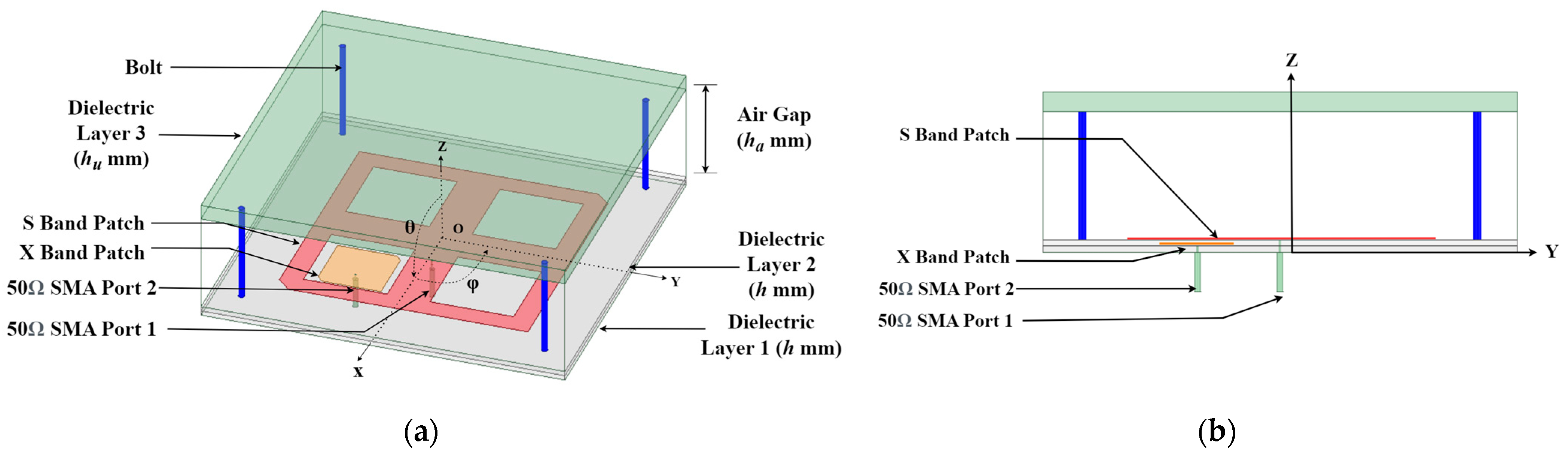
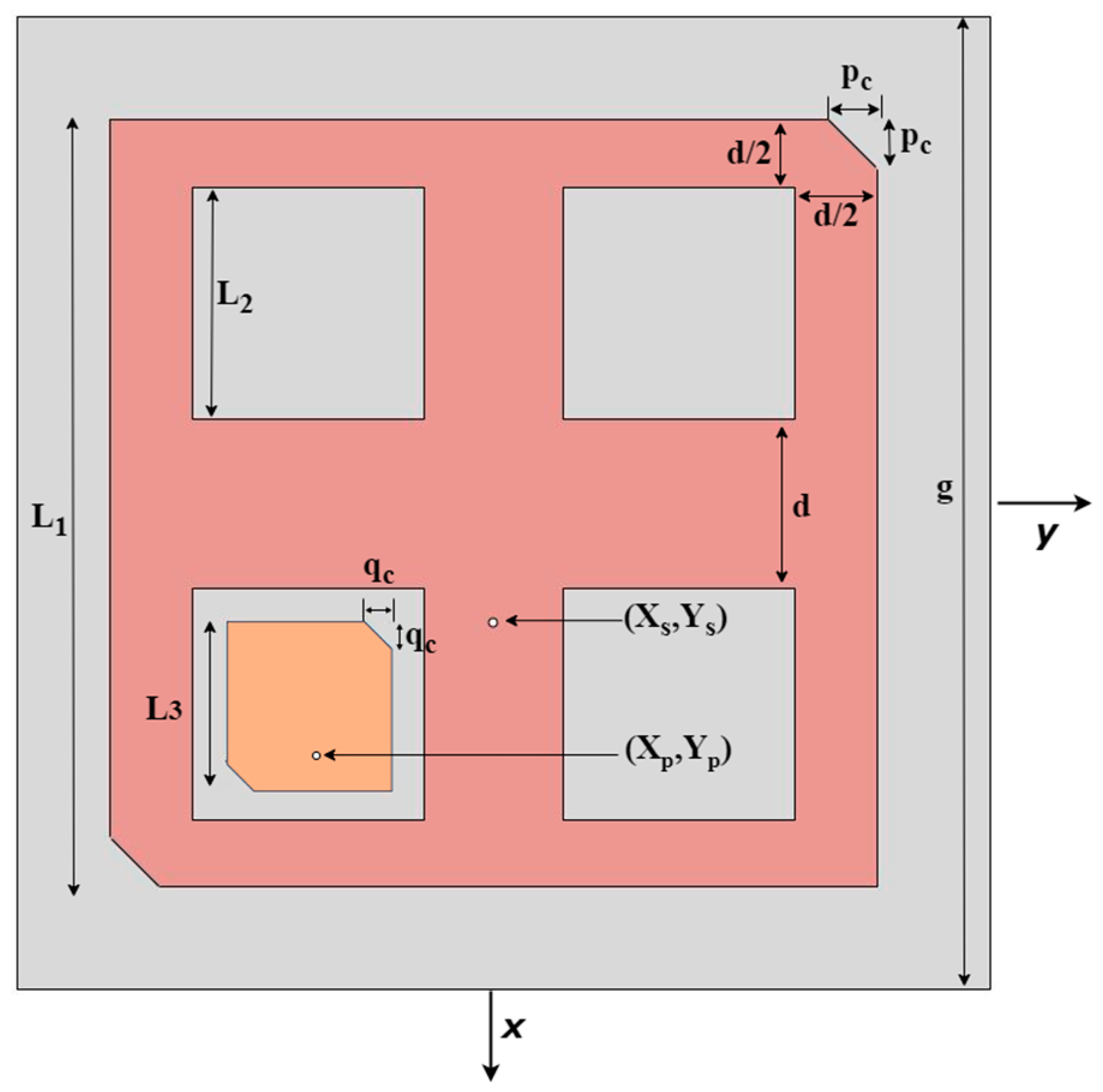
2. Proposed Antenna Geometry

The proposed shared aperture antenna comprises three square-shaped dielectric layers and two square-shaped microstrip printed elements for the S-band and X-band operation. The S-band antenna is designed for use with the uplink/downlink communication system for telemetry, tracking, and command (TT&C) data reception and transmission. The sole objective of the X-band antenna is to downlink large mission data gathered by the CubeSat to the ground station within a short ground pass. To serve the same purposes, CubeSats are normally equipped with two separate conventional antennas. This proposed antenna is compact in size, and due to its planer ground shape, it can be easily integrated with the CubeSat structure.
Figure 1 shows the structure of the proposed antenna. The dielectric layer-1 of the antenna is h mm thick Rogers RT/duroid 5880. The square-shaped copper ground plane of the antenna has a length of g mm and thickness of 35 µm and is placed at the bottom of the dielectric layer-1. The X-band patch is placed on the upper surface of the dielectric layer-1. The X-band square patch antenna has a length of L3 mm with a negative perturbation of qc mm. The dielectric layer-2 is stacked on top of the dielectric layer-1. This layer also has am h mm-thick Rogers RT/duroid 5880 material. Any copper cladding from the bottom of the dielectric layer-2 is removed. On top of the dielectric layer-2, a slotted square-ring patch with a crossed strip at the center is etched, which operates as the S-band antenna [23]. It has a length of L1 mm and negative corner perturbation of pc mm, as shown in Figure 2. Four equal-sized square-shaped slots or perforations are present inside the S-band square ring antenna. An X-band patch antenna can be placed in the middle of any of these four slots, making sure that the S-band ring patch does not block the radiation of the X-band patch antenna. A patch antenna operating in the X-band is placed in the bottom-left slot, as shown in Figure 2. Two separate 50Ω coaxial probes are used to feed the S-band and X-band patch antennas. The dielectric layer-3 is made of hu mm-thick Rogers RT/duroid 6010. It is placed on top of the second dielectric layer using nonconductive bolts. An air gap of ha mm separates the dielectric layers 2 and 3. Dielectric layer-3 works as a partial reflective surface (PRS) for the X-band patch antenna. Placing the PRS at an approximate 0.5λxx is the wavelength at the resonance frequency of the X-band patch antenna) distance away from the X-band antenna means that a Fabry–Perot Resonator Cavity Antenna (FPRA) [24] is formed. FPRAs can exhibit high gain compared to normal patch antennas.
The center of the antenna is placed at the origin of the coordinate system, as shown in Figure 2. The feed location of the S-band patch and the X-band patch is given with respect to the origin. The antenna has a total volume of 60 × 60 × 20 mm3. Table 1 describes the parameters of Figure 1 and Figure 2 and their optimized values for the proposed antenna.

3. Results

The proposed antenna was modeled and optimized using the finite element method-based full-wave electromagnetic solver Ansys HFSS 2022. Based on the simulation results from HFSS, a prototype of the antenna was built. The measured results from the antenna prototype are compared below with the simulated results.

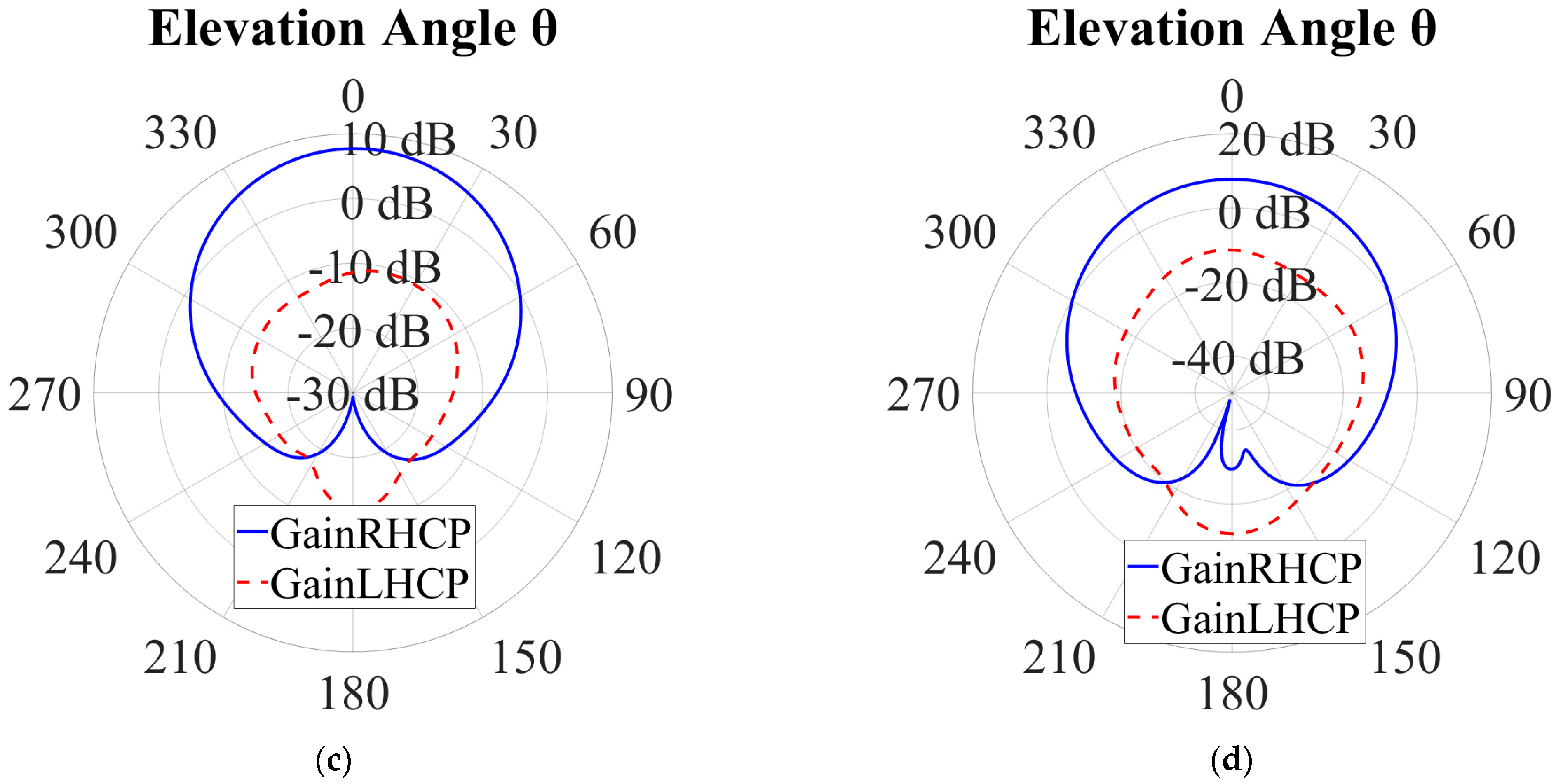
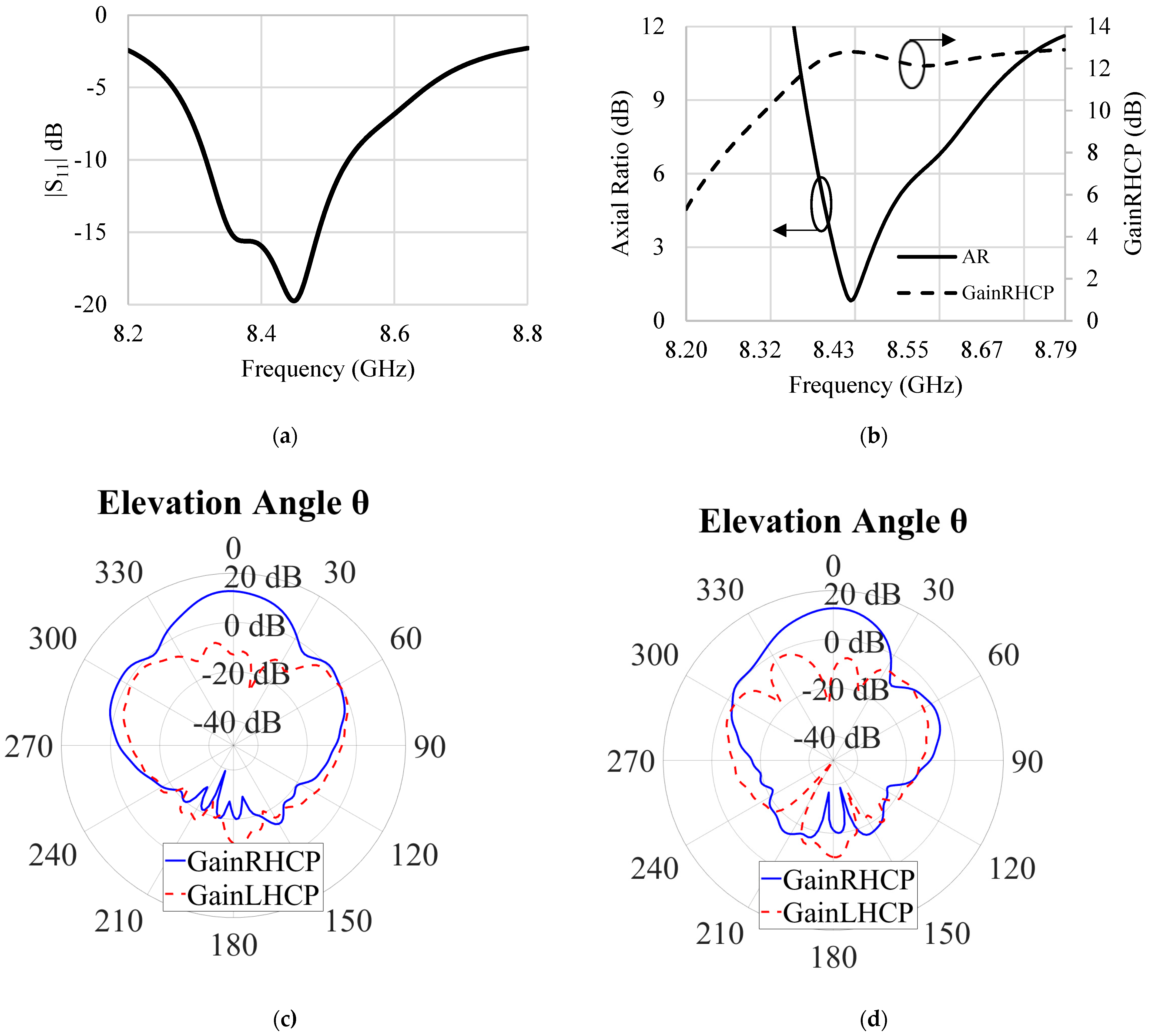
3.1. Simulated Results

Figure 3 shows the simulated performance of the S-band patch for the proposed shared aperture antenna. The S11 < −10 dB bandwidth of the S-band patch is 30 MHz (from 2013 MHz to 2043 MHz, 1.5%). The Axial Ratio (AR) of the proposed antenna is measured in the boresight (+z axis in Figure 1) direction. The simulated AR < 3 dB bandwidth starts from 2013 MHz to 2020 MHz (7 MHz, 0.35%), as shown in Figure 3b. It has a minimum AR value of 1.9 dB at 2016 MHz. Figure 3c,d show the polar plots of the RHCP and LHCP radiation patterns for the patch in the φ = 0° and φ = 90° planes, respectively. It is clear in the plot that the RHCP is more dominant, and the maximum RHCP gain is 7.7 dBic at 2016 MHz. From the radiation patterns of the S-band antenna, it is evident that the antenna has a peak RHCP gain at the boresight. Due to the partial reflective surface, the antenna has a slightly higher gain compared to conventional S-band patch antennas.
Figure 4 depicts the simulated results of the X-band patch of the proposed antenna. The S11 < −10 dB bandwidth of the proposed X-band FPRA starts from 8320 MHz and ends at 8530 MHz (210 MHz, 2.5%). It has an AR < 3 dB bandwidth that ranges from 8433 MHz to 8500 MHz (67 MHz, 0.8%), as shown in Figure 4b, measured in the boresight (+z axis in Figure 1) direction. A simulated maximum RHCP gain of 12.8 dBic was achieved from the single X-band patch antenna. This increased gain from a single radiating patch is close to the gain achieved for a 4-element antenna array [25]. The minimum AR = 0.9 dB of the X-band patch occurred at 8460 MHz. Figure 4c,d show the RHCP and LHCP gain patterns of the proposed antenna in the φ = 0° and φ = 90° planes, respectively. These patterns occurred at the frequency 8460 MHz, where the Axial Ratio is the lowest (0.9 dB). The RHCP beam of the X-band patch antenna was more direct due to the PRS being placed at an approximate 0.5λxx being the free-space wavelength at X-band frequency) distance away from the X-band patch. From the simulated results, it can be concluded that the proposed dual-band shared aperture antenna is an excellent option to replace two antenna systems of a CubeSat and to cover two bands. The S-band patch has a narrow bandwidth, but it is sufficient to perform as the uplink/downlink antenna for TT&C due to the fact that the data speed required to send/receive commands to the CubeSat is not that high. The X-band patch shows a high RHCP gain, which is desirable for establishing a fast downlink connection. The 67 MHz Axial Ratio bandwidth of the proposed antenna can establish Megabits per second (Mbps) and a speed communication link with a ground station.

3.2. Antenna Prototype Fabrication and Measurement

A prototype of the proposed antennas was developed in the Applied Electromagnetics Research Lab at the University of South Alabama, and reflection coefficients were measured using an Anritsu 37369A Vector Network Analyzer (VNA). Figure 5 shows the fabricated prototype of the proposed antenna. Figure 5a,b show the S-band and X-band microstrip patches etched on two separate dielectric substrates. These two dielectric layers were placed on top of each other, and four nonconductive screws and bolts were used to ensure that there were no air gaps between them. Nonconductive spacers ensured that a uniform distance between the patch and the partially reflective surface was maintained.
Figure 6 compares the return loss from measurement and simulation results. From the return loss graphs, it appears that the fabricated antenna prototype produced similar results. The measured S11 < −10 dB bandwidth in the S-band was 16 MHz, which was 30 MHz in the simulation. This difference was due to the slightly higher reflection coefficient of the fabricated antenna compared to the simulated one. In the case of the X-band patch, the measured return loss bandwidth was 270 MHz, whereas the simulation showed a 210 MHz bandwidth. The differences in the simulation and measurement results could be attributed to some fabrication errors, including the misalignment of various layers of this antenna and maybe the presence of some air gaps between layers. The fabricated prototype exhibited good isolation between ports of the S-band and X-band patches (below −20 dB in the S-band and −15 dB in the X-band).

4. Discussion

The proposed antenna shows a way to design a shared aperture antenna by etching microstrip patches in different layers of dielectric materials and, thus, reuse the aperture for the size reduction in the antenna. The lower and higher operating bands of the proposed shared aperture antenna had a frequency ratio of four. Having a high frequency ratio means that the antenna can be used for two separate communication systems that require two antennas. As CubeSats have a very small form factor and different design restrictions, the proposed antenna can be an excellent option for CubeSat missions that have difficulties accommodating multiple antennas. Table 2 compares the performance of the proposed antenna with recent published works on shared aperture antennas for CubeSat application [26,27,28].
From the Table, it is evident that the proposed antenna achieved similar or better performances while keeping the antenna size compact. Both S/X-band antennas in [25,26] had an array of patch antennas for high gain in the X-band, which required a feed network. The dual-band antenna in [28] consisted of a 1 × 3 linear array antenna for the X-band operation, which had 6 ports in total for dual-polarization. Our proposed antenna has only two ports and provides a high gain due to the dielectric loading. Moreover, the proposed antenna uses coaxial probe feeding, which is desirable for CubeSat developers due to the low complexity of cable placement from the radio to the antenna in a concise space.

5. Conclusions

This paper showcases a patch antenna operating in the X-band frequency range with 12.8 dbic gain, positioned between two substrates, with another S bands slotted on a crossed-strip microstrip patch located above, generating a gain of 7.7 dBic. A notable reduction in the size was observed, replacing two antennas next to one antenna system, which could be handy in a CubeSat limited in space. This antenna can be used for S-band uplink/downlink and X-band high-speed data downlink in CubeSats. As more CubeSat projects are looking at high-frequency operations for deep space communication with increased data download requirements, this antenna can be used in CubeSats for use with NASA’s Near-Earth Network (NEN) and Deep Space Network (DSN) for high-speed data transmission in the X-band, and TT&C operation in the S-band.

Author Contributions

Conceptualization, S.S.K. and S.I.L.; methodology, S.S.K.; software, S.S.K.; validation, S.S.K., M.H.K. and S.I.L.; formal analysis, S.S.K.; investigation, S.S.K.; resources, S.I.L.; data curation, S.S.K.; writing—original draft preparation, S.S.K. and M.H.K.; writing—review and editing, S.I.L.; visualization, S.S.K. and S.I.L.; supervision, S.I.L.; project administration, S.I.L.; funding acquisition, S.I.L. All authors have read and agreed to the published version of the manuscript.

Funding

This research has received partial external funding provided by the National Science Foundation (Award Number: AGS 1936537).

Data Availability Statement

Not Applicable.

Conflicts of Interest

The authors declare no conflict of interest.

References

  1. Gao, S.; Clark, K.; Unwin, M.; Zackrisson, J.; Shiroma, W.A.; Akagi, J.M.; Maynard, K.; Garner, P.; Boccia, L.; Amendola, G.; et al. Antennas for Modern Small Satellites. IEEE Antennas Propag. Mag. 2009, 51, 40–56. [Google Scholar] [CrossRef]
  2. Liddle, J.D.; Holt, A.P.; Jason, S.J.; O’Donnell, K.A.; Stevens, E.J. Space Science with CubeSats and Nanosatellites. Nat. Astron. 2020, 4, 1026–1030. [Google Scholar] [CrossRef]
  3. Cappelletti, C.; Battistini, S.; Malphrus, B. (Eds.) Cubesat Handbook: From Mission Design to Operations; Academic Press: Cambridge, MA, USA, 2020. [Google Scholar]
  4. The CubeSat Program, California Polytechnic State University—San Luis Obispo “CubeSat Design Specification Rev. 13”; California Polytechnic State University: San Luis Obispo, CA, USA, 2014.
  5. Imbriale, W.A.; Boccia, L. Space Antenna Handbook; Wiley Online Library: Hoboken, NJ, USA, 2012. [Google Scholar]
  6. Le Vine, D.M.; Jacob, S.D.; Dinnat, E.P.; De Matthaeis, P.; Abraham, S. The Influence of Antenna Pattern on Faraday Rotation in Remote Sensing at L-Band. IEEE Trans. Geosci. Remote Sens. 2007, 45, 2737–2746. [Google Scholar] [CrossRef]
  7. Deshpande, M.; Piepmeier, J. Design and Development of VHF Antennas for Space Borne Signal of Opportunity Receivers for CubeSat Platforms. In Proceedings of the IEEE International Symposium on Antennas and Propagation and North American Radio Science Meeting, Vancouver, BC, Canada, 19–24 July 2015. [Google Scholar]
  8. Joseph, A.T.; Deshpande, M.; O’Neill, P.E.; Miles, L. Development of VHF (240–270 MHz) antennas for SoOp (Signal of Opportunity) Receiver for 6U CubeSat Platforms. In Proceedings of the 2016 Progress in Electromagnetic Research Symposium (PIERS), Shanghai, China, 8–11 August 2016; pp. 2530–2531. [Google Scholar]
  9. Chahat, N.; Sauder, J.; Thomson, M.; Hodges, R.; Rahmat-Samii, Y. CubeSat deployable ka-band reflector antenna for deep space missions. In Proceedings of the 2015 IEEE International Symposium on Antennas and Propagation & USNC/URSI National Radio Science Meeting, Vancouver, BC, Canada, 19–24 July 2015; pp. 2185–2186. [Google Scholar]
  10. Hodges, R.E.; Radway, M.J.; Toorian, A.; Hoppe, D.J.; Shah, B.; Kalman, A.E. ISARA-integrated solar array and reflectarray cubesat deployable ka-band antenna. In Proceedings of the 2015 IEEE International Symposium on Antennas and Propagation & USNC/URSI National Radio Science Meeting, Vancouver, BC, Canada, 19–24 July 2015; pp. 2141–2142. [Google Scholar]
  11. Warren, P.A.; Steinbeck, J.W.; Minelli, R.J.; Mueller, C. Large, Deployable S-band antenna for a 6U CubeSat. In Proceedings of the 29th Annual American Institution Aeronautics and Astronautics/Utah State University Conference Small Satellites, Santa Clara, CA, USA, 8–13 August 2015; pp. 1–7. [Google Scholar]
  12. Tubbal, F.E.; Raad, R.; Chin, K.W. A Survey and Study of Planar Antennas for Pico-Satellites. IEEE Access 2015, 3, 2590–2612. [Google Scholar] [CrossRef]
  13. Vourch, C.J.; Drysdale, T.D. Inter-CubeSat communication with V-Band ‘Bull’s Eye’ antenna. In Proceedings of the 8th European Conference on Antennas and Propagation (EuCAP 2014), Hague, The Netherlands, 6–11 April 2014; pp. 3545–3549. [Google Scholar]
  14. Hossain, M.M.; Kabir, S.S.; Latif, S.I.; Spencer, E.; Qudrat-E-Maula, M. A wideband stacked patch-patch antenna with hybrid perturbations for circular polarization. In Proceedings of the 2021 IEEE International Symposium on Antennas and Propagation and USNC-URSI Radio Science Meeting (AP-S/URSI), Singapore, 4–10 December 2021; pp. 55–56. [Google Scholar]
  15. Liu, S.; Theoharis, P.I.; Raad, R.; Tubbal, F.; Theoharis, A.; Iranmanesh, S.; Abulgasem, S.; Khan, M.U.A.; Matekovits, L. A Survey on CubeSat Missions and Their Antenna Designs. Electronics 2022, 11, 2021. [Google Scholar] [CrossRef]
  16. Axness, T.A.; Coffman, R.V.; Kopp, B.A.; O’Haver, K.W. Shared Aperture Technology Development. Johns Hopkins APL Tech. Dig. 1996, 17, 285–294. [Google Scholar]
  17. Wang, S.; Zhang, L.; Zhu, K.; Sun, H. Multi-band shared aperture circularly polarized antenna with metal isolation columns. In Proceedings of the 2022 IEEE MTT-S International Wireless Symposium (IWS), Harbin, China, 12–15 August 2022; pp. 1–3. [Google Scholar]
  18. Xie, M.; Wang, Z.; Sun, L.; Zhu, S.; Deng, G.; Cao, Z. An L/S multi-band shared-aperture circularly polarized antenna. In Proceedings of the 2021 13th International Symposium on Antennas, Propagation and EM Theory (ISAPE), Zhuhai, China, 1–4 December 2021; pp. 1–3. [Google Scholar]
  19. Gaffar, M.; Zaman, M.A.; Choudhury, S.M.; Matin, M.A. Design and Optimisation of a Novel Dual-Band Circularly Polarised Microstrip Antenna. IET Microw. Antennas Propag. 2011, 5, 1670–1674. [Google Scholar] [CrossRef]
  20. Rivera, A.; Stewart, A. Study of spacecraft deployables failures. In Proceedings of the European Space Mechanisms and Tribology Symposium, Virtual, 20–24 September 2021. [Google Scholar]
  21. Kabir, S.S.; Latif, S. Multi-band shared aperture antenna for satellite communications. In Proceedings of the 2022 IEEE International Symposium on Antennas and Propagation and USNC-URSI Radio Science Meeting (AP-S/URSI), Denver, CO, USA, 10–15 July 2022; pp. 1814–1815. [Google Scholar]
  22. Rao, S.; Shafai, L.; Sharma, S.K. (Eds.) Handbook of Reflector Antennas and Feed Systems Volume III: Applications of Reflectors; Artech House: Norwood, MA, USA, 2013. [Google Scholar]
  23. Chen, W.-S.; Wu, C.-K.; Wong, K.-L. Square-Ring Microstrip Antenna with a Cross Strip for Compact Circular Polarization Operation. IEEE Trans. Antennas Propag. 1999, 47, 1566–1568. [Google Scholar] [CrossRef]
  24. Orr, R.; Goussetis, G.; Fusco, V. Design Method for Circularly Polarized Fabry–Perot Cavity Antennas. IEEE Trans. Antennas Propag. 2013, 62, 19–26. [Google Scholar] [CrossRef]
  25. Abbak, M.; Tekin, I. RFID Coverage Extension Using Microstrip-Patch Antenna Array. IEEE Antennas Propag. Mag. 2009, 51, 185–191. [Google Scholar] [CrossRef]
  26. Mathur, P.; Kumar, G. Dual-Frequency Microstrip Antenna at S and X Bands with Higher-Order Mode Suppression Technique. IET Microw. Antennas Propag. 2018, 12, 583–587. [Google Scholar] [CrossRef]
  27. Serup, D.E.; Williams, R.J.; Zhang, S.; Pedersen, G.F. Shared aperture dual S- and X-band antenna for nano-satellite applications. In Proceedings of the 2020 14th European Conference on Antennas and Propagation (EuCAP), Copenhagen, Denmark, 15–20 March 2020; pp. 1–4. [Google Scholar]
  28. Bandi, R.B.; Kothapudi, V.K.; Pappula, L.; Kalimuthu, R.; Gottapu, S.K. A Single-Layer S/X-Band Shared Aperture Antenna with MIMO Characteristics at X-Band for Airborne Synthetic Aperture Radar Applications. Int. J. Antennas Propag. 2023, 2023, 1384388. [Google Scholar] [CrossRef]
Figure 1. Proposed S- and X-band shared aperture antenna (a) Antenna structure in isometric view; (b) Side view of the antenna.
Electronics 12 04439 g001
Figure 2. Geometry of the proposed S- and X-band patches.
Electronics 12 04439 g002
Figure 3. Performance of the S-band patch of the proposed antenna, (a) Return loss (b) Axial Ratio and peak RHCP gain vs. frequency (c) RHCP gain and LHCP gain patterns at 2016 MHz in the φ = 0° plane (d) RHCP gain and LHCP gain patterns at 2016 MHz, in the φ = 90° plane.
Electronics 12 04439 g003aElectronics 12 04439 g003b
Figure 4. X-band patch antenna simulated results, (a) return loss (b) AR and peak RHCP gain vs. frequency (c) RHCP, LHCP gain patterns at 8460 MHz in the φ = 0° plane (d) RHCP, LHCP gain patterns at 8460 MHz in the φ = 90° plane.
Electronics 12 04439 g004
Figure 5. Fabricated prototype of the proposed antenna, (a) S-band patch (b) X-band patch (c) Proposed antenna (Isometric view) (d) Ground plane and SMA probes (viewing from bottom).
Electronics 12 04439 g005
Figure 6. Comparison of measured and simulated return loss of the proposed antenna and measured isolation between two ports: (a) S-band patch; (b) X-band patch.
Electronics 12 04439 g006aElectronics 12 04439 g006b
Table 1. The design parameters of the S- and X-band-shared aperture antenna.
Antenna PartsParametersSymbolValue (mm)
Antenna Main StructureDielectric Layer-1 heighth0.787 mm
Dielectric Layer-2 heighth0.787 mm
Air gap distanceha16.2 mm
Dielectric Layer-3 heighthu2.5 mm
All dielectric layers and ground Plane lengthg60 mm
S-band PatchSquare Ring antenna lengthL141.7 mm
Square Ring antenna slot lengthL213.8 mm
Square Ring patch corner perturbation lengthpc2.2 mm
Distance between slotsd7.05 mm
Square Ring antenna feed location(Xs, Ys)(5.7, 0) mm
X-band PatchX-band square patch lengthL3 10.8 mm
X-band square patch corner perturbation lengthqc1 mm
X-band patch feed location(Xp, Yp)(12.3, −10.4) mm
Table 2. Performance comparison of the proposed antenna with other related work.
Ref.Freq. BandsAR BW (%)Gain (dBic)Antenna Volume (mm3)Polarization
[26]S-/X-bandNA8/11.5140 × 140 × 9.4 Linear
[27]S-/X-band1/1.46.55/12.582 × 82 × 4RHCP
[28]S-/X-bandNA7.2/12.4100 × 100 × 1.6Linear
Proposed
work
S-/X-band0.35/0.87.7/12.860 × 60 × 20RHCP
Disclaimer/Publisher’s Note: The statements, opinions and data contained in all publications are solely those of the individual author(s) and contributor(s) and not of MDPI and/or the editor(s). MDPI and/or the editor(s) disclaim responsibility for any injury to people or property resulting from any ideas, methods, instructions or products referred to in the content.

