1. Introduction
Nowadays, the utilization of wind energy has gained extensive concern all over the world. Because of their merits, such as decoupled control and small converter size, traditional doubly fed induction generator (DFIG)-based wind turbines have been popularly installed on wind farms over the past decades. Nevertheless, the DFIG’s electric brushes and slip rings degrade system reliability and increase its maintenance cost [
1,
2,
3,
4,
5,
6,
7,
8,
9]. By comparison, a new type of multiport electric machine, the brushless doubly fed generator (BDFG), not only inherits the advantages of traditional DFIG but also overcomes its aforementioned disadvantages, such as canceling the electric brushes and slip rings and having better low voltage ride-through (LVRT) capability [
2,
3,
4,
5,
6,
7,
8,
9,
10]. Thus, the use of BDFG can greatly enhance the reliability of wind generation systems and lower their cost. It therefore has promising prospects in energy conversion applications. The operation of BDFG can be stand-alone [
11,
12,
13,
14,
15,
16] or grid-connected [
1,
2,
3,
4,
5,
6,
7,
8,
9]. Usually, in stand-alone operation, the frequency and voltage are controlled for load, whereas in grid-connected operation, active and reactive power are adjusted according to the requirements of the power grid. In a wind generation system, the BDFG is usually driven by a wind turbine. The structure of grid-connected, wind-driven BDFG (WDBDFG) is described in
Figure 1. As described, the WDBDFG system consists of a wind turbine, gearbox, BDFG, grid-side converter (GSC), machine-side converter (MSC), and controllers. Among them, BDFG is composed of power winding (PW), control winding (CW), and a specially designed rotor winding (RW), which can be divided into rotor power winding (RPW) and rotor control winding (RCW).
The modeling and controls for BDFG-based generation systems under balanced networks have been well studied in [
17,
18,
19,
20,
21,
22,
23,
24]. Nevertheless, as shown in
Figure 1, due to the direct connection between the PW of BDFG and the network, BDFG is very susceptible to network disturbances such as network voltage unbalance. The negative sequence component of unbalanced network voltages will lead to the unbalance of PW currents, distortions of RW and CW currents, pulsations of PW power, and machine torque [
25,
26,
27]. These adverse effects have deleterious effects on WDBDFG and even lead to damage to its electrical and mechanical parts. Thus, it is very necessary to study the control methods for WDBDFG under network unbalance so as to improve the capability to resist the network unbalance. Thus far, the modeling and control for WDBDFG under network unbalance have been investigated in [
25,
26,
27,
28,
29]. Nevertheless, the controls in [
25,
28,
29] have similar drawbacks, including adopting a double-closed loop control structure, involving the decomposition of both CW and PW current sequence components, and the cross-coupling terms in control loops being totally or partially neglected. These drawbacks lead to a very complex control structure, and system-decoupled control is also affected. In addition, since it was not CW current references but the PW current references under different control objectives were deduced, a double-closed loop design was needed. In order to address the problems mentioned above, improved controls were proposed in [
26,
27], where a single-loop proportional-integral (PI) controller for CW current was proposed to realize the control objectives set. Moreover, because feedforward control was also applied in the CW loop by using all the disturbances and couplings deduced, decoupled control was also improved. Nevertheless, in [
26,
27], a dual PI controller including a positive and a negative sequence CW current controller was designed, and the extraction of positive and negative sequences of CW currents was still necessary. However, because the extraction process can introduce significant amplitude and phase errors, the dynamic response of CW current is affected, and CW current cannot realize fully decoupled control during the transient process. Furthermore, the multi-use of the decomposition algorithm also increases the complexity of the control structure. Additionally, for BDFG (MSC), only one control objective of canceling pulsations of torque and PW reactive power was discussed, and a corresponding control reference of CW current was deduced; other control objectives such as canceling pulsations of CW current, PW current unbalance, and PW active power pulsations were not studied.
The above problems in existing studies weakened the control capability of WDBDFG to resist network unbalance. To overcome these problems, an improved control strategy for WDBDFG under network unbalance is proposed in this paper. In the proposed control, a proportional-integral-resonant (PIR) current controller composed of proportional, integral, and resonant regulators is designed. The main contributions include the following:
(1) For WDBDFG (MSC), apart from the control objective of canceling pulsations of torque and PW reactive power, another three control objectives, including eliminating pulsations of CW current, eliminating the unbalance of PW current, and eliminating pulsations of PW active power, are discussed. Furthermore, it was the CW current references but not the PW current references under different control objectives that were deduced. This provides a basis for the design of an improved PIR current controller with a single-closed loop structure.
(2) An improved single-loop CW current controller using a PIR regulator is designed to control CW current to track the references under network unbalance. Compared to the existing dual PI control, where the sequence extraction of CW current is necessary, in the proposed PIR control, CW currents are not involved with sequence extraction and can be totally regulated only in a positive synchronous reference frame. Hence, in contrast with current controls using a dual PI controller, the proposed control is greatly simplified, and dynamic characteristics are improved. Also, the proposed control is more applicable. Furthermore, in order to obtain completely decoupled control of current and average power, feedforward control using all the couplings and perturbances deduced is also applied in CW current loops.
Simulation tests for a 2 MW grid-connected WDBDFG verify that the proposed control is capable of achieving four control objectives and exhibits good stable and dynamic control characteristics under network unbalance.
2. Modeling of BDFG under Network Unbalance
Under an unbalanced network, the mathematical model of BDFG in a PW positive sequence synchronous (
dpqp)
+ rotary frame can be given as follows [
14,
15,
26,
27,
29]:
where
,
, and
represent voltage space vectors of PW, CW and RW in (
dpqp)
+ rotary reference frame, respectively;
,
, and
represent current space vectors of PW, CW, and RW in (
dpqp)
+ rotary reference frame;
,
, and
represent flux space vectors of PW, CW, and RW in (
dpqp)
+ rotary reference frame, respectively;
rp,
rc,
rr,
Lp,
Lc, and
Lr represent resistance and self-inductance of PW, CW, and RW;
Lpr and
Lcr represent mutual inductance between PW and RW and CW and RW;
p represents differential operator;
ωp,
ωc and
ωpr represent the frequency of PW, CW, and RPW, respectively;
= 0,
ωc =
ωp − (
pp +
pc)
ωr,
ωpr =
ωp −
ppωr;
ωr represent rotor rotating speed;
pp and
pc represent the pole pairs of PW and CW, respectively; subscripts
p,
c, and
r represent PW, CW, and RW.
The spatial relationships of BDFG between
αpβ
p reference frame,
αcβ
c reference frame revolving at speed (
pp +
pc)
ωr, α
rβ
r reference frame revolving at speed
ppωr, (
dpqp)
+ reference frame revolving at speed
ωp, and (
dpqp)
− reference frame revolving at speed –
ωp is shown in
Figure 2. In
Figure 2,
θp and
θr represent the position angle of the positive sequence of PW flux and rotor position angle, respectively.
When network voltage is unbalanced, the physical quantities of BDFG can be extracted as positive and negative sequences. Thus, on the basis of
Figure 2, the unbalanced space vectors
m, including voltages, currents, and fluxes, are expressed in the (
dpqp)
+ rotary frame as follows:
where superscripts +, − are (
dpqp)
+ and (
dpqp)
− rational frames, and subscripts +, − are positive and negative sequences.
In the (
dpqp)
+ rotary frame, according to (1)~(6), the CW voltage equation under network unbalance can be represented as follows [
26,
27]:
where
σ = 1 −
L2crLp/(
LprLMLc),
denotes the perturbances and the couplings and can be written as follows:
where
LM = (
LrLp/
Lpr) −
Lpr.
Under network unbalance, the instantaneous active and reactive powers of PW and electromagnetic torque are represented as follows [
26,
27]:
where
Pp0,
Pps2,
Ppc2, Qp0,
Qps2,
Qpc2,
Tem0,
Tems2, and
Temc2 are the average values and the amplitudes of pulsation terms of PW active and reactive powers and electromagnetic torque, respectively, and can be given as follows:
where
3. Control Objectives for WDBDFG under Network Unbalance
Under network unbalance, according to (7), there exists unbalance in PW current and distortion in CW current, and according to (10), (11), and (12), there exist pulsations in electromagnetic torque and PW active and reactive powers, respectively. These adverse effects are very harmful to wind-driven BDFG, and power systems even lead to damage to BDFG’s electrical and mechanical parts and instability of the power system. Thus, in order to overcome these adverse effects and improve the control capability under network unbalance, the control objectives of WDBDFG can be designated as canceling CW current pulsations, keeping PW current balance, canceling pulsations of PW active and reactive powers, or machine torque pulsations, which are analyzed as follows:
Control objective (1): Canceling CW current pulsations, namely, = = 0. This control objective ensures that CW is heated evenly.
Control objective (2): Keeping PW current balance, namely, = = 0. This control objective ensures that PW is heated evenly.
Control objective (3): Canceling pulsations of PW active power, namely, Pps2 = 0 and Ppc2 = 0. In such instances, the MSC is controlled to cancel the pulsations in PW active power.
Control objective (4): Canceling pulsations of torque and PW reactive power, namely, Tems2 = 0, Temc2 = 0, Qps2 = 0, and Qpc2 = 0. This control objective reduces the mechanical stress and cancels the pulsations in PW reactive power.
For the sake of simplifying the design of system control, the PW flux
oriented method can be adopted for WBDFG (MSC); therefore, as described in
Figure 2, there are
= 0. As a result, ignoring the smaller
Rp and considering (7), Equation (1) can be simplified at steady state as follows:
Control objective (1) requires
= 0. As a result, according to (11) and (13), the positive and negative sequences of CW current reference are deduced as follows:
where
and
are the active and reactive power references of PW.
Control objective (2) requires
= 0. Using (4), RW current is derived as follows:
Substituting (15) into (6) yields the following:
By substituting (15) and (16) into (3), the RW voltage equation can be expressed as follows:
According to (17), by neglecting RW resistance
Rr and transient processes, Equation (15) can be deduced as follows:
Substituting
= 0 into (18) yields the following:
Hence, according to (11), (13), and (19), the required CW current reference is deduced as follows:
For
Control objective (3), by using (13) and substituting
Pps2 = 0 and
Ppc2 = 0 into (11), the corresponding CW current reference can be deduced as follows:
For
Control objective (4), similarly, by using (13), substituting
Qps2 = 0 and
Qpc2 = 0 into (11) or substituting
Tems2 = 0 and
Temc2 = 0 into (12), and PW power references into (11), the corresponding CW current reference can be deduced as follows [
26,
27]:
It is worthy of noting that, compared to controls in [
26,
27], apart from the control objective of canceling pulsation of machine torque and PW reactive power, another three control objectives, including eliminating oscillations of CW current, eliminating the unbalance of PW current, and eliminating oscillations of PW active power, are also discussed, and the corresponding CW current references are derived. Moreover, compared to controls in [
25,
28,
29], it was CW current references but not PW current references under different control objectives that were deduced; this provides a basis for the design of an improved PIR current controller with a single-closed loop structure.
4. Proposed PIR CW Current Controller
For the purpose of realizing the control objectives under network unbalance, according to (14) and (20)–(22), the required CW current references of
,
,
and
can be obtained. As a consequence, the CW (MSC) current controller should be designed so that the measured CW currents are capable of tracking the required CW current references. Usually, a dual PI controller including a positive sequence current controller in the (
dpqp)
+ reference frame and a negative sequence current controller in the (
dpqp)
− reference frame is employed [
26,
27,
29]. Hence, the sequence extraction for CW currents was needed, but the sequence extraction can bring considerable time delays and amplitude errors to CW current, which would affect the decoupling control of CW current under transient conditions and further worsen the dynamic characteristics of the whole control system. Furthermore, the multi-use of the decomposition algorithm also increases the complexity of the control structure. Aiming at these problems, an improved single-loop CW current controller using a PIR regulator is designed to control CW current to track the references under network unbalance.
Under network unbalance, it can be seen from (7) that, in the (
dpqp)
+ reference frame, the CW (MSC) current is transformed into a positive sequence (DC value) plus a negative sequence (2
ωp AC sinusoidal value). Theoretically, in order to eliminate steady-state errors, the DC value can be controlled using a PI regulator, while the AC sinusoidal value can be controlled using an R regulator at a resonant frequency of 2
ωp. Thus, in the (
dpqp)
+ reference frame, CW current can be precisely controlled by a PIR regulator without the need for sequence extraction. The differences between PI and PIR regulators can be summarized in
Table 1.
Based on previous analysis and (7) and (8), the PIR regulator for CW (MSC) current can be designed using feedback and feedforward controls as follows:
In (23) and (24), kp, ki, and kr denote the proportional, integral, and resonant coefficients of the proposed PIR current regulator; 2ωp represents the resonant frequency determined by network frequency ωp; ωct represents the cut-off frequency used to adjust the sensitivity to frequency 2ωp; and represent the control references of CW voltages on the (dp)+ and (qp)+ axes; and and shown in (9) denote the terms used for feedforward control.
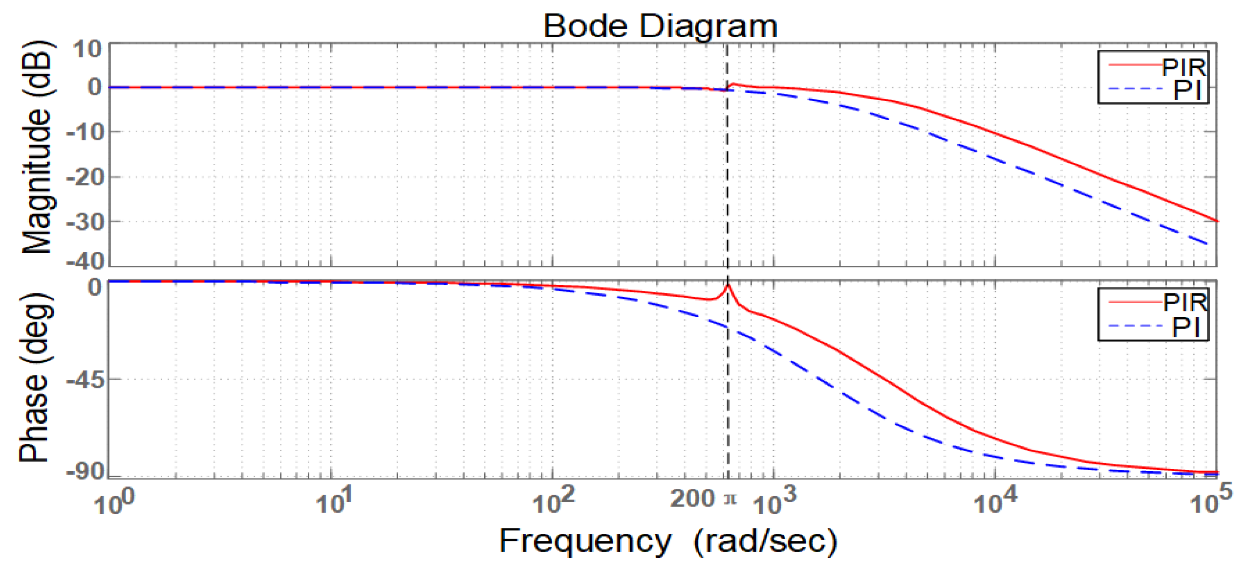
According to (8), (23), and (24), the proposed PIR CW current controller is depicted in
Figure 3. On the basis of
Figure 3, the bode diagrams of the closed-loop transfer function are depicted in
Figure 4, where
ki = 3,
kp = 20,
kr = 400, and
ωct = 3 rad/s. For comparison,
Figure 4 shows the bode diagrams using PI and PIR controllers. As shown in
Figure 4, there are larger amplitude and phase errors at the 2
ωp (200 π rad/s, 100 Hz) frequency signal for the CW closed-loop transfer function using the traditional PI regulator. By contrast, when a PIR regulator is used, there are nearly no amplitude or phase errors at the 2
ωp (200 π rad/s, 100 Hz) frequency signal.
Figure 5 shows the bode diagrams of the CW current open-loop transfer function. As can be seen, crossover frequencies, the gain, and the phase margins of using PI and PIR controllers have little difference. Consequently, the system of using a PIR regulator is almost as stable as using a PI regulator.
According to
Figure 2 and Equation (7), the overall CW (MSC) control voltage in the CW stationary reference frame is deduced as follows:
It should be noted that, in
Figure 3, feedforward control using
and
is also applied in CW current loops so as to obtain completely decoupled control of current and average power. Moreover, it can be seen from (23)–(25) that the applicability of the proposed strategy is limited by the maximum output voltage and current of MSC, i.e., the maximum capacity of MSC. Generally, the larger the MSC-rated capacity, the better the control capability of the proposed control, and the higher the network unbalance.
5. Whole Proposed Control Strategy
On the basis of
Section 3 and
Section 4, the whole control strategy for grid-connected WDBDFG (MSC) under network unbalance is shown in
Figure 6. As shown, under different control targets, the CW current references are directly computed by using (14) and (20)–(22), respectively. Furthermore, as analyzed before, in the CW current controller, after 3/2 and
αβ/
dq transformations, the measured CW currents are totally transformed into the (
dpqp)
+ reference frame, and obviously, they are not involved with sequence extraction. Then, controlled with PIR regulators, the CW control voltages
and
are outputted, and finally, after SVPWM modulation, the switch states for MSC are generated. Additionally, in
Figure 6, for the purpose of calculating the references of CW current, sequence extraction for PW voltages and fluxes is required. Furthermore, a phase-locked loop (PLL) is required so as to fix the d+ axis on the positive sequence of PW flux revolving at the angular speed of
ωp. There are various sequence extraction methods reported in the literature. Most of them make a tradeoff between accuracy and dynamic response. Comparatively, the multiple-complex coefficient-filter (MCCF)-based sequence extraction method in [
30] has much better performance and, hence, is employed in the proposed control. With such an approach, the positive and negative sequences can be quickly and accurately extracted under network unbalance and distortion.
Figure 7 illustrates the structural diagram of the MCCF-based PLL and sequence extraction method, where both
ωc and
ω1 are equal to 314 rad/s.
It is worth noting that the proposed control shown in
Figure 6 is much simpler than existing controls. The improvement in the simplification of the control structure includes the following three aspects:
(1) In existing controls, a dual PI controller, including a positive and a negative sequence CW current controller, is usually designed. With a dual PI controller, a total of four positive and negative sequence components of CW current (positive sequence components on the d and q axes and negative sequence components on the d and q axes) are required to be controlled by using four PI regulators in two reference frames (positive and negative reference frames); hence, the parameters of the four PI regulators need to be tuned, and the structure of system control is very complex. In contrast, in the proposed control, a single PIR controller for CW current only in one reference frame (the positive reference frame) is designed. With the proposed control, the CW current (not its positive and negative sequence components) can be totally controlled just by using two PIR regulators in one reference frame (the positive reference frame).
(2) In existing controls, the decomposition algorithm for CW current is necessary. However, in the proposed control, the CW current can be totally controlled by using PIR regulators, and the decomposition algorithm for CW current is not required.
(3) In existing controls, usually a double-closed-loop control structure composed of a PW power or PW current outer loop and a CW current inner loop is designed. This is because the control references of CW current are not directly derived, and the output of the PW power or PW current outer loop is used as the control reference of the CW current inner loop. In contrast, in the proposed control, the control references of CW current are directly derived; therefore, a single-closed-loop control structure of CW current is enough, and a PW power or PW current outer loop is not required.
6. Simulation Verification
For the purpose of verifying the feasibility of the proposed control strategy, simulation tests for a WDBDFG system under network unbalance were implemented with Matlab-Simulink (software 7.8.0(R2009a)). The nominal power of WDBDFG is 2 MW, and its parameters are given in
Table 2. This paper aims at the modeling and control of MSC (BDFG), and the controls of GSC have been investigated in [
26,
27]. Hence, here, it is assumed that the control objective for GSC is to maintain the voltage of the DC bus at 1200 V.
Figure 8 illustrates the waveforms under the constant revolving speed of 1.1 p.u. and 9% network unbalance, where four different control objectives analyzed in
Section 3 are applied to MSC. The PW power reference
and
were 1.0 p.u. and 0 MVar, respectively. The control objective of the MSC was originally selected as
Control objective (1), then changed to
Control objective (2) at 0.2 s,
Control objective (3) at 0.4 s, and finally
Control objective (4) at 0.6 s. As illustrated in
Figure 8c, during 0–0.2 s, CW currents have no pulsations. When
Control objective (2) is applied at 0.2 s, the unbalance of PW current disappears immediately in
Figure 8b. Similarly, as shown in
Figure 8e, when
Control objective (3) is designated at 0.4 s, the pulsations in PW active power cancel. Finally, when
Control objective (4) is selected at 0.6 s, the pulsations of the generator’s torque and the reactive power of the PW disappear at the same time, which is clearly illustrated in
Figure 8f and
Figure 8g, respectively. Moreover, according to
Figure 8d,
,
,
and
all contain DC values plus 100 Hz pulsations;
and
track with the references
and
very well; this attributes to the PIR controller analyzed in
Section 4. Additionally, as illustrated in
Figure 8e,f, the actual average values of output PW active and reactive powers are 1.0 p.u. and 0 MVar, which also follows the references very well. The PW current (
Ip) unbalance, CW current (
Ic) percentage of 105 Hz harmonic relative to the 5 Hz fundamental component, 100 Hz pulsations in the PW active and reactive powers (
Pp,
Qp), and generator’s torque are also summarized and compared in
Table 3. Obviously, the results in
Table 3 are consistent with the waveforms in
Figure 8. Hence, it is evident from
Figure 8 and
Table 2 that the four selectable control objectives, including no CW current oscillations, balanced PW current, eliminating pulsations of PW active power, canceling the pulsations in electromagnetic torque, and output reactive power of PW, have been fully achieved, respectively.
Further study under the working condition of varied rotor speed from sub-synchronous state to super-synchronous state is also implemented by using the proposed control strategy. The PW active power reference
is originally equal to 0.5 p.u., and at 1.4 s, it steps up from 0.5 p.u. to 1.0 p.u. The PW reactive power reference
is originally equal to −0.25 p.u. (capitative reactive power) and steps up from −0.25 p.u. (capitative reactive power) to 0.25 p.u. (inductive reactive power) at 1.6 s. Rotor rotary speed varies from 0.7 p.u. (sub-synchronous state) to 1.3 p.u. (super-synchronous state) during 0.2 s to 1.2 s. The network unbalance is 8.5%.
Figure 9 illustrates the waveforms of variable rotor speed.
Figure 10A,B illustrate the comparisons of the waveform with conventional vector control, where network unbalance is not considered, and the proposed control, respectively. In the proposed control, the control objective was originally selected as
Control objective (1), then changed into
Control objective (4) at 0.5 s. As illustrated in
Figure 10A(a,b), there exist severe unbalances in PW current and distortions in CW current. Moreover, as illustrated in
Figure 10A(d–f), PW output active and reactive powers and generator torque all have large 100 Hz pulsations. By contrast, as illustrated in
Figure 10B(a–c,f), when PW active power stepped up at 1.4 s, PW current, CW current, and electromagnetic torque also increased. Likewise, as illustrated in
Figure 10B(b,c,e,f), during 0–0.5 s, the control objective of canceling oscillations of CW current is attained, and during 0.5–2 s, the control objective of canceling pulsations of reactive power and torque is realized as expected. Furthermore, as illustrated in
Figure 10B(d,e), the control of PW active and reactive powers is decoupled and presents very good dynamic characteristics once again. Consequently, compared to conventional vector control, the proposed control is able to significantly enhance the capability of WDBDFG to resist network unbalance. In addition, as illustrated in
Figure 9, when rotor speed is equal to 1.0 p.u. (i.e., the synchronous speed) at 0.7 s, it can be seen from
Figure 10B(b,e,f) that at CW currents become DC current and
Control objective (4) is achieved as expected; furthermore, nearby 0.7 s, CW currents are smoothly controlled to complete the change of phase sequence. Thus, at or near the synchronous state, the proposed control still shows good control performance.
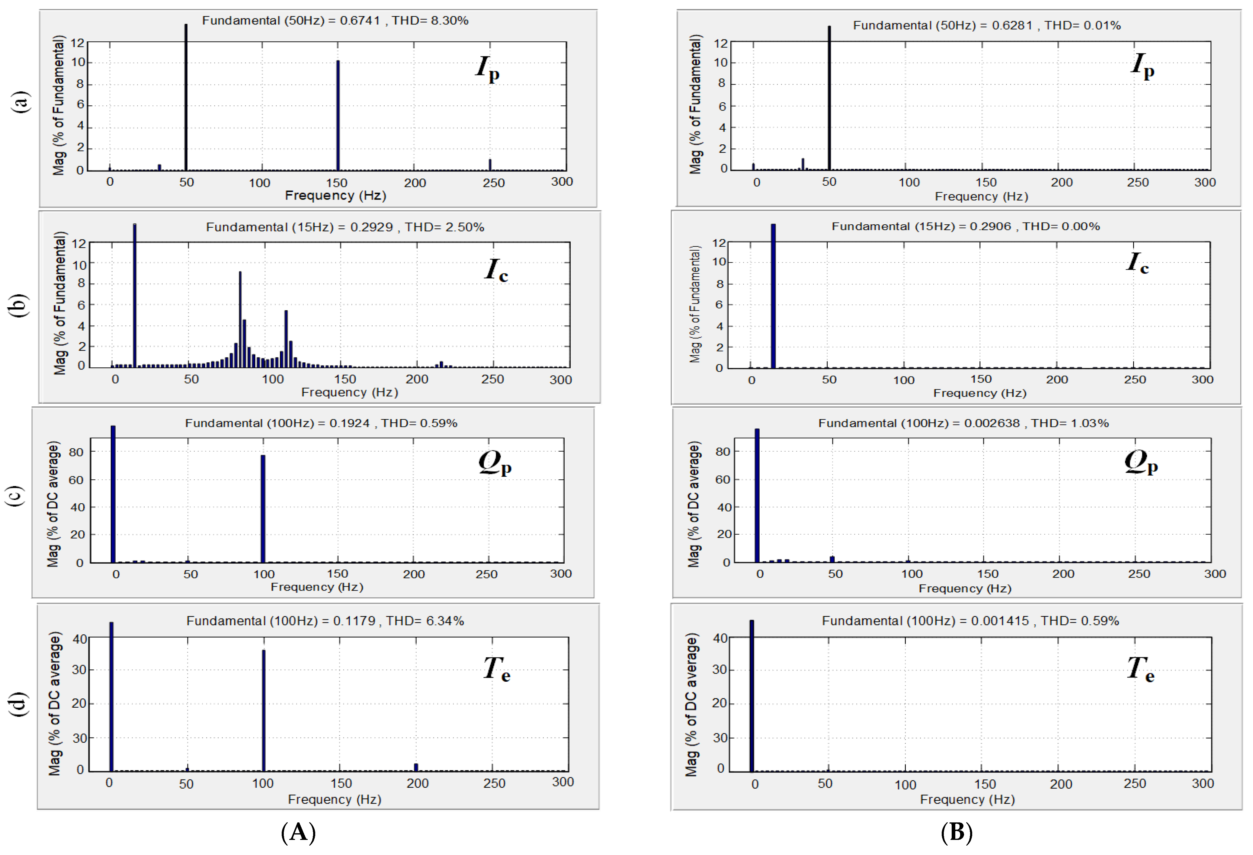
Figure 10 and
Figure 11A,B illustrate the spectrums of harmonics with conventional vector control and proposed control, respectively. As illustrated in
Figure 11A(a–d), with conventional vector control, apart from fundamental frequency components, namely, 50 Hz in PW current and 15 Hz in CW current when ω
r is 0.7 p.u., PW current also contains 150 Hz harmonics, and CW current mainly contains 85 Hz and 115 Hz harmonics. In addition, there are 100 Hz pulsations in both reactive power and the generator’s torque. By contrast, it can be clearly seen from
Figure 11B(a,b) that, when the proposed control is used and
Control objective (1) is selected, the harmonics in PW and CW currents disappear. Moreover, according to
Figure 11B(c,d), where
Control objective (4) is selected, 100 Hz pulsations in reactive power and the generator’s torque are eliminated at the same time. Consequently, the feasibility of the proposed control is verified again.
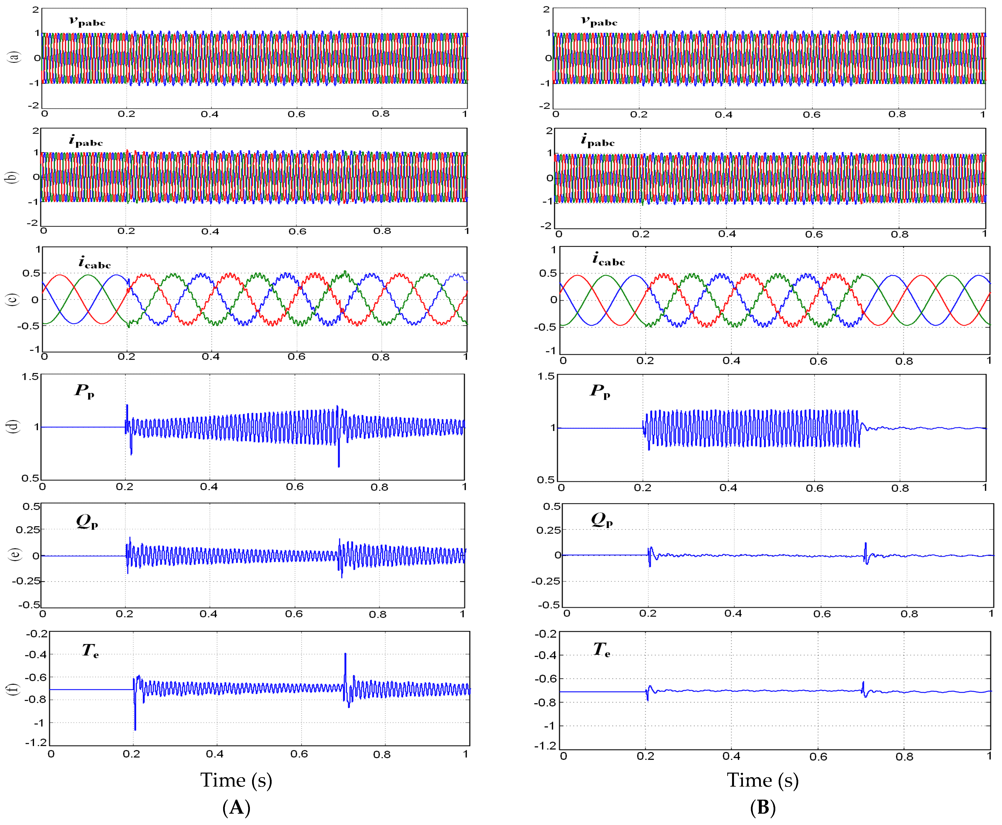
In order to further test the improvements of the proposed control in dynamic performance, a study on the control of the WDBDFG system under transient network unbalance was also implemented. The transient network voltage unbalance of 9% appears at 0.4 s and disappears at 0.7 s; before 0.4 s and after 0.7 s, network voltage keeps balance. Two current controllers, namely, dual PI control in existing controls [
26,
27,
29] and the proposed control, are compared, and the results are illustrated in
Figure 12. Rotor rotary speed is kept at 1.1 p.u.; the power references
and
were 1.0 p.u. and 0 MVar, respectively. The control objectives of both controls are set as
Control objective (4), i.e., canceling pulsations of torque and PW reactive power.
Figure 12A illustrates the dynamic responses using the dual PI control in the existing control. In such control, the positive and negative sequence CW current controllers are designed. With a dual PI controller, a total of four positive and negative sequence components of CW current (positive sequence components on the d and q axes and negative sequence components on the d and q axes) are required to be controlled by using four PI regulators in two reference frames (positive and negative reference frames). Obviously, in order to obtain positive and negative sequence components of CW current, the decomposition algorithm for CW current is necessary. As illustrated in
Figure 12A(a–c), from 0 s to 0.2 s, network unbalance voltage is balanced, and both
Ipabc and
Icabc are balanced. When transient network unbalance appears during 0.2 s to 0.7 s,
Ipabc and
Icabc become unbalanced and distorted. However, when network voltage returns to balance from 0.7 s to 1 s,
Ipabc and
Icabc cannot return to balance in a short time but still remain unbalanced and distorted. Moreover, according to
Figure 12A(d–f), when transient network unbalance appears during 0.2 s to 0.7 s, very large oscillations in
Qp and
Te appear and cannot be eliminated. Thus,
Control objective (4) cannot be realized under transient network unbalance with dual PI control. In addition, when network voltage returns to balance during 0.7 s to 1 s, very large oscillations in
Pp,
Qp, and
Te appear again and cannot disappear in a short time. According to testing results, dual PI control in existing controls presents poor dynamic performance. This is because sequence extractions of CW currents bring significant amplitude and phase errors to the control system, which affects the dynamic performances of CW currents and further worsens system dynamic characteristics. By comparison,
Figure 12B illustrates the dynamic responses using the proposed control. As illustrated in
Figure 12B(b–f), when network unbalance appears at 0.3 s and disappears at 0.7 s, the dynamic process is much more smoothly and quickly than that in
Figure 12A(b)–B(f). Furthermore, according to
Figure 12B(c,d), when network voltage returns to balance at 0.7 s,
Ipabc and
Icabc return to balance quickly (the response time is approximately 5 ms). In addition, according to
Figure 12A(d–f), during 0.2 s to 0.7 s, the oscillations in
Qp and
Te are small and eliminated in a short time (the response time is approximately 12 ms). Thus,
Control objective (4) is totally achieved as expected. In addition, when network voltage returns to balance at 0.7 s, the oscillations in
Pp,
Qp, and
Te are also small and disappear quickly. In summary, the proposed control has much better dynamic performance than existing controls under network unbalance.


