1. Introduction
Robotics is an experimental science; one that involves integration between heterogeneous fields such as electronics, mechanics, computer science, control theory and artificial intelligence. Some of the technologies used by these various fields, e.g., simulation engines [
1,
2], embedded single-board computers [
3,
4], programming languages [
5,
6,
7], algorithms [
8,
9,
10,
11], modeling paradigms [
12,
13,
14] etc., are rapidly changing over time to keep up with advances in science, information technology and electronics. During the design, development and deployment of robotic systems, the components that belong to the various sub-systems, e.g., image processing software, servo motors, power distribution system etc., must work congruously to achieve a common goal. The integrated software in robotics must be flexible and robust enough to handle variabilities during a development cycle such as changes in sensors, control logic or performance modes. Hardware replacements/changes may be necessary during the lifetime of a robot, that can sometimes neither be foreseen during the initial design nor be simple.
One way to reasonably tackle the variabilities in such tightly integrated systems is to develop a model-driven tool that formalizes and promotes rapid system-level design, development, integration, and reuse; one that enables quick changes during design-time and run-time. During the life-cycle of a robotics project,
models of the robotics software, and hardware are refined until the robot performs satisfactorily enough to meet both its design specification and user’s expectations. Model-driven component-based software engineering (CBSE) and development [
15,
16,
17,
18,
19] has become an accepted practice for tackling software complexity in large-scale embedded robotic software. CBSE tackles escalated demands with respect to requirements engineering, high-level design, error detection, tool integration, verification and maintenance. The widespread use of component technologies in the market has made CBSE a focused field of research in the academic sectors. Applications are built by assembling together small, tested component building blocks that implement a set of services. These building blocks are typically built from design models and captured in UML [
20] class diagrams, or imported from other projects/vendors and
connected together via exposed interfaces, providing a “black box” approach to software construction. This approach also treats software verification in a more modular fashion; the various software components can be verified individually and then composed together to derive a functional system.
The component model that is described in this paper also backs this idea of analysis and verification; the model provides guidelines to users for code development and exhibits well-defined execution semantics that makes the run-time application behavior more amenable to analysis. Though not in the scope of this paper, we have published in previous work some timing [
21,
22,
23] and network analysis methods [
24,
25,
26] that have examined the timing and network properties of composed component assemblies, using component models such as ROSMOD, with the component execution semantics presented here.
Along with the component model, this paper also describes the ROSMOD infrastructure, which includes a modeling language, a graphical user interface, code generators, deployment and run-time management features. We discuss the utility of ROSMOD in a real-world case study, the Autonomous Ground Support Equipment (AGSE) robot, that was designed and built by the Vanderbilt Aerospace Design Laboratory, which competed and won the NASA Student Launch Competition (2014–2015).
1.1. Changes Since RSP 2015
The work presented in this paper is an extension of a ROSMOD prototype framework [
27]. The work presented here is a fully revised, re-designed, implementation of the core principles; the design decisions regarding the modeling language, artifact management, and deployment and monitoring infrastructure are derived from our experiences with this prototype. The goal of this re-implementation, and therefore also this paper, is to present a framework that aims to be optimized for rapid system development from the perspective of the developer. The prototyped ROSMOD work was implemented with Python, using a GUI development framework called wxPython [
28]. This implementation used a simple textual language with an interactive graphical rendering environment, but also had several caveats that often lead to state corruption, and made true collaborative development impossible. Also, this framework did not allow developers to start
jobs asynchronously through the various aspects in the framework, e.g., it is impossible in this prototype to start multiple experiments at the same time in the same instance of ROSMOD, i.e., the developer has to complete tests/experiments sequentially.
In this paper, we present a fully re-designed ROSMOD that relies on a stable in-house modeling environment, called WebGME [
29]. This ROSMOD framework supports asynchronous job scheduling, collaborative code development and model editing features, a more complete meta-model with various integrated analysis features, and a more robust deployment and run-time management infrastructure. Lastly, we have chosen to integrate the code development and compilation process within the graphical user interface in order to keep the framework self-sufficient. This means that code development, code generation, compilation, process deployment, run-time monitoring, and execution time plot generation can all be done within the ROSMOD framework, i.e., a web page; this level of integration is completely streamlined and new to ROSMOD.
1.2. Terms Used in this Paper
Project: A collection comprised of a software model, a set of system models, a set of deployment models, and a set of experiments.
Package: A package refers to an application, i.e., a software sub-system.
Component: a re-usable software building-block of an application.
Component Instance: an instance of a component, properties of which can be overridden by the instance.
Port: a communications interface connecting one component to other components.
Client: a port providing blocking, synchronous request-response interactions.
Server: a port receiving and responding to client requests.
Publisher: a port providing anonymous one to one or one to many message passing interactions.
Subscriber: a port receiving data from one or more publishers.
Timer: a mechanism used to periodically or sporadically trigger a component.
Host: a single computer running a Linux-based operating system.
System: a collection of networked hosts.
System Model: a model of system
Node: a POSIX process that executes a collection of components in parallel.
Deployment Model: A mapping between component instances and nodes
Experiment Model: A mapping between a deployment model and a system model
Experiment: the act of executing nodes in a subset of system hosts, specified by the experiment model.
2. Related Research
Software engineering tools and practices for robotics is a large, rapidly evolving field encompassing many disciplines. Much of the progress in this field can be found in the IEEE International Conference on Simulation, Modeling, and Programming for Autonomous Robots (SIMPAR) [
30], the Workshop on Domain-Specific Languages and models for Robotic Systems (DSLRob) [
31], and the Journal of Software Engineering for Robotics (JOSER) [
32].
In the field of Robotics and embedded systems, a large number of component models have been presented and evaluated in literature. These component models fall under one of two categories: (1) component models that implicitly adopt a specific middleware, or programming language and (2) component models that are deliberately general purpose, enabling its use over a wider range of applications. Here, we discuss a few state of the art component models that have been developed and improved over the last 10–15 years and designed for robotic system development and integration.
The CORBA Component Model (CCM) [
33] is one such model, pushed by the Object Management Group [
34] as a standardized middleware specification to promote distributed real-time systems. CCM components are defined through an object-based component definition language which uses an IDL [
35] for interface description. Fully defined components are implemented, where the implementation describes how the component pieces interact with each other. The resulting implementations are packaged into shared libraries and linked dynamically by the run-time system. CCM also provides a deployment mechanism to deploy the components in a CORBA component server; deployment instructions are specified by XML files. CCM components can interact with other components using
ports. CCM supports four basic types of ports: facets, receptacles, event sources, and event sinks. Facets are
provided interfaces that present functionality to other interacting components. Provided interfaces define operations that can be invoked either synchronously or asynchronously. A receptacle is a
required interface; using receptacles, components can connect with other component instances and invoke operations. Event sources and sinks provide event-based communication between component instances. A component can either publish or subscribe to events. To address the issue of CORBA having a heavy memory/storage footprint, UCM [
36] is being designed and developed as an alternative OMG standard providing interoperability with CCM and other component models/middlewares.
Similarly, SmartSoft [
37,
38,
39] is a component model for robotic software, that uses communication patterns and is characterized by dynamic run-time configuration of components. SmartSoft aims to provide a generic software architecture without enforcing a specific robot architecture. There exists a CORBA-based implementation called CORBA SmartSoft that uses the TAO ORB [
40] implementation of CORBA, as well as an implementation based on ACE [
41]. A SmartSOft component is implemented as a set of threads and interacts with other components using well-defined communication patterns. Components can be dynamically configured at run-time to exhibit specific communication patterns.
Orca [
42] is an open-source component model for component-based software development for mobile robots. The Orca framework attempts to impose very few constraints on developers, i.e., developers are free to design components that can provide or require any set of interfaces and the implementations for these interfaces can be provided as necessary. There are also little to no architecture constraints during the composition of Orca components. The Orca component model relies on a middleware that can handle the issues of communication protocols and provide a means for interactions between components. Orca implementations have been released with both CORBA and the Internet Communication Environment (ICE) [
43]. Similar to other component models here, interface descriptions and interactions are configured using XML configuration files, per component.
The Open Robot Control Software (OROCOS) [
44] is a component-based software framework for robotic control software development in both real-time and non-real-time operating systems. OROCOS supports event-driven interaction between components, where each component consists of a set of properties, ports, operations, and a single activity, i.e., a task with a defined execution frequency. Similar to CCM, the system is configured by a
deployer (using XML) which declares all OROCOS components and port connections. The execution semantics of each component is described using an internal finite state machine, including initialization, pre-operation, start, update, and clean up states. The OROCOS framework is available both standalone and as part of the Robot Operating System (ROS), a middleware platform used by the ROSMOD platform presented in this paper.
In the past, our team has designed, implemented and tested the F6COM/DREMS component model [
45] for tackling software engineering challenges in distributed real-time embedded systems. Each DREMS component supports four basic types of ports for interaction with other collaborating components: Facets, Receptacles, Publishers and Subscribers. A component’s
facet is a unique interface that can be invoked either synchronously via remote method invocation (RMI) or asynchronously via asynchronous method invocation (AMI). A component’s
receptacle specifies an interface required by the component in order to function correctly. Using its receptacle, a component can invoke operations on other components using either RMI or AMI. A
publisher port is a single point of data emission and a
subscriber port is a single point of data consumption. Communication between publishers and subscribers is contingent on the compatibility of their associated topics (i.e., data types). More details on this component model can be found in [
45].
ROS [
46] is a free, open-source meta-operating system framework that facilitates robotic system development. ROS is widely used in various fields of robotics including industrial robotics, UAV swarms and low-power image processing devices. The open source multi-platform support and language-neutral design of ROS has made it a requirement in several DARPA robotics projects including the
DARPA Robotics Challenge [
47]. The ROS component model defines nodes, packages, messages, topics and services. Nodes represent the software components and are deployed as processes.
ROS 2.0 [
48], while originally proposed to build off of other communications middlewares such as ZeroMQ [
49], has been designed to leverage DDS [
50] as the underlying communications framework. These pre-existing communications libraries provide the distributed communications functionality which made ROS useful in robotics, and provide much of the interaction pattern specification and implementation relevant for specifying a component model.
The BRICS [
51] project aims to provide structure and formalization for developing robots and for increasing interoperability of robot hardware and software components through well defined interfaces on its component model [
52] and by providing an integrated development environment, BRIDE [
53], based on the Ecplipse [
54] platform. BRICS, through BRIDE, supports model-based and component-based code generation for various robotics libraries such as OROCOS and ROS.
The current version of Matlab’s Simulink [
18] supports the
Robotics System Toolbox [
55] (RST), using which ROS developers can model ROS workspaces as Simulink blocks, generate executable code, while also exploiting Matlab’s large suite of simulation and analysis tools. Unfortunately, the RST was not available to us under our existing academic license. Aside from the costs, our experience shows that it is fairly difficult to modify the Matlab generated code, as well as the modeling language (Simulink), or, for instance, enforce specific scheduling policies, or support the component model constructs that are possible in ROSMOD.
Some infrastructures, like OPRoS [
56], provide model transformations and integration tools to couple existing component models and suites with ROS. In case of OPRoS, the framework enables development of OPRoS applications that can communicate with ROS applications. The model transformations help users use the OPRoS platform to develop ROS applications but the expected semantic behavior of the applications, as seen in these models, may not necessarily match the runtime system. Also, such tool suites are relevant to ROS users only if they are also interested in using OPRoS and do not directly focus on ROS development.
In this paper, we describe ROSMOD, an open-source development tool suite and run-time software platform for rapid prototyping of component-based software applications using ROS. This software organization consists of several software pieces: (1) A Model-driven development environment; (2) plugins for code generation, software deployment, and run-time management; (3) visualizers for user-defined views of the models and artifacts, e.g., plots generated from run-time logs; and finally (4) the run-time platform: the ROSMOD component model that is distributed as an installable ROS package. The component model in ROSMOD is similar to F6COM in the execution semantics and threading model of the component, i.e., each component has an executor thread, a message queue to receive requests/messages from other components, and the component execution scheduler—the non-preemptive nature of the operation scheduling in each component. The reason for this choice is also to be able to directly apply some formal timing and network analysis methods we have developed in the past, based on F6COM and the DREMS infrastructure, with little to no changes in the analysis models. Additionally, the non-preemptive operation scheduling means that component developers do not have to write locking or synchronization primitives for data shared between operations in the same component.
ROSMOD relies on ROS for serialization, message passing and discovery. Since much of the back-end communication is ROS, ROSMOD also uses ROS’s description language for message and service data structures. However, it must be noted that this is not a strong binding. The modeling language, and rapid system integration methods presented in this paper are not strictly tied to ROS, aside from some naming conventions. The code generation and deployment framework in ROSMOD is loosely coupled with the models and therefore, much of this can be swapped out as needed. We are currently in the process of supporting other middleware technologies, e.g., ZeroMQ [
49] and OMG DDS [
57], and using serialization methods such as Google Protocol Buffers [
58], though this integration work isn’t with in the scope of this paper.
3. ROSMOD Component Model
The ROSMOD component is a refinement of the ROS component model. In this section, we detail some of the aspects of both component models, describe the differences and present the execution semantics of ROSMOD. Many of the design decisions in ROSMOD, are motivated by the need to keep the model of the software simple and easy to prototype/analyze.
The ROS component model defines messages, topics, services, packages, and nodes. Nodes represent the software components in ROS and are deployed as independent processes on a local machine or on a set of networked computers. Nodes communicate with each other by sending/receiving messages. In ROS, messages are strictly-typed data structures, defined by language-independent IDL. Complex messages can be constructed by using the primitive data types supported by the IDL, that are composed to arbitrary depth. Upon compilation, ROS messages are translated into serializable data structures. Topics support asynchronous communication and Services support synchronous communication between nodes.
Nodes can send messages to other nodes by publishing data to a given topic. A node that is interested in this data can subscribe to the appropriate topic. When a new message is received by the subscribing node, a callback function is asynchronously called to handle and receive the message in the user-space. Alternatively, a ROS node can perform a synchronous method invocation on another node using services. A service is characterized by two typed messages: the request message, and the response message. The client node populates the request message and calls the service; the server node receives the request and responds to the client by populating the response message. ROS nodes are grouped into packages. A package is an application that can be compiled, and executed, i.e., a package represents the minimal compilable unit of ROS. Packages can also be used to wrap external libraries.
In ROSMOD, software components, as shown in
Figure 1, can contain a variety of ports and timers. Publisher ports publish messages, without blocking, on a message topic. Subscriber ports subscribe to such topics and receive all messages published on the specified topic. This interaction implements an anonymous topic-driven publish-subscribe message passing scheme [
59]. Server ports provide an interface to a component service. Client ports can use this interface to request such services. Clients and servers implement a blocking peer-to-peer synchronous remote method invocation (RMI) interaction [
60]. Component timers can be periodic or sporadic and allow components to trigger themselves with the specified timing characteristics. These aspects of ROSMOD are quite similar to ROS. The main difference between ROS and ROSMOD is the threading model and the execution semantics of software components. As described earlier, the software components in ROS are ROS nodes which are independent processes. In ROSMOD, each component is represented by an executor thread and a component operation queue, as shown in
Figure 1.
ROSMOD Component Execution Semantics
An
operation is an abstraction for the different tasks undertaken by a component. These tasks are implemented by the component’s source code written by the developer. Application developers provide the functional,
business-logic code that implements operations on local state variables and inputs received on component ports. For example, a PID controller [
61] could receive the measured value of a process variable from a
sensor component, and using the relevant gains and set points (desired value for the process variable), calculate a new state to which an
actuator component should progress the system.
In order to service interactions with the underlying framework and with other components, each component has a message queue. This queue holds operation requests received from another component, i.e., messages, service requests, and timer activations. Each request is characterized by a priority and a deadline. Priority refers to the relative importance of one operation over another within the scope of the component. Deadline refers to the worst-case duration from the arrival of a triggering event to the completion of the response operation. If the execution of the operation takes beyond its deadline to complete, then a deadline violation is said to have occurred.
Each ROSMOD component has a separate execution thread that handles the execution of all component operations. This executor thread picks the next available request from the message queue and executes the operation to completion, i.e., the operation scheduling is non-preemptive. So, all operations in the queue, regardless of priority, need to wait for the currently executing operation to complete. Allowing only a single executor thread per component and enforcing a single-threaded non-preemptive scheduling scheme on the operations helps avoid the need for synchronization primitives for internal state variables and establishes a more easily analyzable system. It is true that multi-threaded solutions to operation scheduling would avoid starvation, i.e., operations in the queue will not have to wait forever if the currently executing operation is blocked on a resource. However, the ROSMOD execution semantics is still the more predictable design as it is more easily analyzable. The non-determinism in multi-threaded executions causes a tree of possible behaviors, leading to a common analysis challenge called state space explosion [
62]. Keeping the operation execution to a single thread per component bounds the overall number of threads in the system leading to a more tractable analysis. However, since these operations are executed without preemption (by other operations within the component), there are scenarios in which the component, set of components, or system can deadlock due to cyclic communications dependencies. A simple example is a component whose timer initiates a blocking client call to a server which is hosted by the same component; because the timer operation is blocked from finishing by the client, the server operation in the queue will never be serviced so the client and thus the timer will never unblock. To enable developers to check their designs for such cyclic communications dependencies, component assemblies can be automatically analyzed to ensure that there will be no deadlocks or operation deadline violations. These analysis techniques and tools are outside the scope of this paper, and have been published in previous work [
21,
22,
23].
Figure 2 shows the execution semantics of a component operation executed on the component’s executor thread. Simplifying assumptions include that this component is the only component thread executing on the CPU, assuming a single core CPU. This is a simple scenario showing how a single operation on a single component is affected by the operation scheduling semantics. The wait times of the remote request are also worsened by OS scheduling non-determinism—when multiple components are scheduled concurrently, fixed-priority thread scheduling is enforced.
ROSMOD components, upon deployment, are dormant. Execution of the application is first initiated by a timer-triggered component. The executor thread of the triggered component wakes up and executes the trigger operation. The application code written in this operation may initiate other triggers and component interactions, thus dictating the behavior of the ROSMOD application. It is important to note that ROS imposes no design constraints or principles on the nodes; a node can be any process with any number of threads. The component model in ROSMOD, i.e., the use of a single executor thread and a non-preemptive operation queue, enable a stricter variant of the base ROS component model—one where each component is essentially a thread, multiple components are grouped in a process (ROS node).
4. ROSMOD Modeling Language
To enable the rapid design, development, and testing of software on robotics and distributed CPS in general, we have developed a domain-specific modeling language (DSML) [
63], the ROSMOD Modeling Language (RML), that begins to address the heterogeneous needs of distributed robotic systems engineering. A DSML is a programming language or specification language that, using appropriate notations and abstractions, offers the expressive power focused on, and usually restricted to, a particular domain, e.g., distributed real-time systems.
The ROSMOD meta-model is captured from the developer mode of our graphical interface for model specification, which allows viewing and modification of the meta model and its rules which govern the construction of ROSMOD models. All objects contain a
name attribute of type
string. Any object shown in the meta figures which has an italics and grayed-out name is a pure
abstract object, which cannot be instantiated in a model and merely serves as the base class for other instantiable classes. Note: the meta-model interface is used to create the ROSMOD Modeling Language, but users do not see or interact with it; it is used to enforce proper model creation semantics. RML captures all the relevant aspects of the software, the system (hardware and network), and the deployment which specifies how the software will be executed on the selected system. Using ROSMOD, developers can create models which contain instances of the objects defined in RML. This approach of using a domain specific modeling language to define the semantics of the models allows us to check and enforce the models for correctness. Furthermore, this approach allows us to develop generic utilities, called
plugins which can act on any models created using ROSMOD, for instance generating and compiling the software automatically or automatically deploying and managing the software on the defined system. The rest of this section goes into the specific parts of the modeling language, called the Meta-Model, and how they define the entities in a ROSMOD Model.
Figure 3 provides a reference legend for all meta-model figures in this section.
The top-level entity of RML is a
Project, which is shown in all of the following meta-model related figures,
Figure 4,
Figure 5,
Figure 6 and
Figure 7. The meta-model has been broken up into separate figures for clarity and ease of understanding. The language supports a variety of modeling concepts that address structural and behavioral aspects for distributed embedded platforms. ROSMOD users can create models of software workspaces, required software libraries, embedded devices, network topologies, component constraints and hardware capabilities. The language also supports code development, particularly with regards to port interface implementations, i.e., the execution code for operations owned and triggered by communication ports or local timers. Below, we describe in detail the various aspects of this meta-model and how these concepts are integral to developing distributed CPS and rapid prototyping needs.
It should be noted that the capability to specify the meta-model within the same tool and interface as the models themselves allow developers and users (if they choose) to extend or modify the meta-model based on their needs or experiences. Support for this kind of dynamic meta-model specification has been critical in the development of ROSMOD, particularly for enabling rapid evolution of the platform and faster feedback when any issues or new requirements are encountered. As such, this meta-model is not provided as a final, gold-standard model which we as developers are promoting for the design and development of all distributed CPS. Rather, this meta-model has arisen from our combined development and deployment experiences over the past few years with various tools. Further, this paper and the tool we present are designed to show the utility of such a framework for rapidly evolving projects, tool-suites, designs, and implementations.
4.1. Software Model
The
Software class in
Figure 4 models a software workspace. A workspace, following ROS terminology, is a collection of applications that are developed and compiled together into binaries. Thus, each Software class can contain ROS applications, called
Packages, and
Libraries required for the applications. Packages consist of
Messages,
Services and
Components. Components contain a set of pointers to Libraries to establish dependence, e.g., an
ImageProcessor component
requires OpenCV, an open-source computer vision library. Libraries are of two types: Source libraries and System libraries. Source libraries are standalone archives that can be retrieved, extracted and integrated into the software build system with no additional changes. System libraries are assumptions made by a software developer regarding the libraries pre-installed in the system. Here, system refers to the embedded device on which the component is intended to execute.
Messages represent the ROS message description language for describing the data values used by the ROS publish-subscribe interactions. Similarly,
Services describe the ROS peer-to-peer request-reply interaction pattern. Each service is characterized by a pair of messages,
request and
response. A client entity can call a service by sending a request message and awaiting a response. This interaction is presented to the user as a remote procedure call. Each ROSMOD component, as described in the component model (
Figure 1), contains a finite set of communication ports. These ports refer to messages and services to concretize the communication interface. Components can also contain
Timers for time-triggered operation, e.g., periodically sampling inertial measurement sensors while operating an unmanned aerial vehicle (UAV). Lastly, components can be characterized by
Constraints. Currently, ROSMOD constraints are a simple way to establish hardware requirements for operation, e.g., fast multi-core processor, quadrature encoded pulse hardware, camera interface etc. When starting such components at runtime, ROSMOD will try to map each component to one of the available devices that satisfies all of the component’s constraints. Specifying constraints for a component can be arbitrarily complex but currently we support simple feature-specific constraints, e.g.,
This component needs a device with at least 12 open GPIO pins to enable motor control. In such cases, ROSMOD will simply scan the set of devices in the hardware model and find a candidate host that
provides such a
capability. More about the deployment infrastructure and the mapping of constraints to capabilities is described in
Section 5.6.
All requests received by a component, via subscribers or servers, and all timed triggers can be prioritized. The prioritization is used primarily by the component scheduler and the chosen scheduling scheme. First-in-first-out (FIFO) scheduling of received operations prioritizes based on the arrival time of the requests. Priority-based FIFO resolves conflicts between received operations by using the Priority attribute of the relevant ports. Similarly, deadline-based schemes like the Earliest-Deadline-First (EDF) scheme uses the deadline of the received operation requests to resolve conflicts and operate safely. The scheduling scheme and operation priorities within a component are important choices to make since these choices directly affect the efficiency and safe operation of components. Highly critical operations need acceptable response times for robotic systems to meet quality and timing specifications. This design criteria is our primary motivation for integrating timing and performance characterization techniques into our software specification and tool suite. The integrated performance and timing measurement system allows for the logging and visualization of system execution traces and to show the enqueue, dequeue, and completion of operations being executed by the component executor thread. As these operations trigger each other, these traces provide valuable feedback to the users about the performance and timing characteristics of the system, allowing the determination of performance bottlenecks and resource contention.
4.2. System Model
A
System Model, see
Figure 5, completely describes the hardware architecture of a system onto which the software can be deployed. A ROSMOD Project contains one or more
Systems. Each System contains one or more
Hosts, one or more
Users, one or more
Networks, and one or more
Links. A host can contain one or more
Network Interfaces, which connect through a link to a network. On this link the host’s interface is assigned an IP, which matches the subnet and netmask specification of the network. Additionally, a host has a set of references to users, which define the user-name, home directory, and ssh-key location for that user. The host itself has attributes which determine what kind of processor architecture it has, e.g.,
armv7l, what operating system it is running, and lastly a combination of Device ID and Device ID Command which provide an additional means for specifying the type of host (and a way to determine it), for instance specifying the difference between a BeagleBone Black and an NVIDIA Jetson TK1 which both have
armv7l architecture but can be separated by looking at the model name in the device tree. Finally, a host may contain zero or more
Capabilities to which the component constraints (described in the previous section) are mapped. The final relevant attribute is the
Network Profile attribute of a link. Using the network profile, which is specified as a time-series of bandwidth and latency values, we can configure the links of the network using the Linux TC [
64] to enforce time-varying bandwidth and latency. This network configuration is useful when running experiments on laboratory hardware for which the network is not representative of the deployed system’s network.
4.3. Deployment and Experimentation
Deployment refers to the act of starting application processes on candidate hosts, where each host can provide for and satisfy all of the constraints of the processes, e.g., general purpose input/output (GPIO) ports, CPU speed etc. Therefore, a deployment is a mapping between application processes and system hosts on which the application processes run. The ROSMOD Deployment Model,
Figure 6, makes this map a loose coupling to enable rapid testing and experimentation. Each Deployment consists of a set of
Containers. Each container, conceptually, is a set of processes that need to be collocated. Containers also ensure that no process outside a container is deployed along with the container once it has been mapped to a host. Each container, therefore, contains a set of
Nodes (ROS terminology for processes). In each node, application developers instantiate one or more components previously defined in the Software model. Following the ROSMOD component model, each such instance maps to an executor thread that executes the operations in the component’s operation queue. Note that the same component can be instantiated multiple times even within the same node. Also note the container is not mapped to a specific host within the deployment model, but rather is automatically mapped to a host by the deployment infrastructure within an
Experiment.
As shown in
Figure 7, each project supports a set of
Experiments. Each experiment has pointers to one System model and one Deployment model. The system model provides the set of available devices and the deployment model provides the set of containers, where each container contains a set of component constraints that need satisfying (the union of all the container’s nodes’ component constraints). ROSMOD uses these sets to find a suitable mapping and then deploys the containers on the chosen host devices, if a mapping can be found which satisfies all the constraints of all the containers. When the deployment infrastructure selects hosts from the system model for mapping, it first checks to see which of the system model’s hosts are (1) reachable; (2) have valid login credentials; (3) have the correct architecture, operating system, and device ID, and (4) are not currently running any other compilation or experiment processes from any other user. In the case that there are no available hosts in the system or the deployment’s constraints cannot be satisfied, the infrastructure informs the user. Upon successful deployment of the experiment, the infrastructure automatically stores the specific mapping relevant to the deployed experiment for later management and destruction. When such experiments are stopped, ROSMOD retrieves the component logs from the hosts and displays results. We are currently working on improving our runtime monitoring features to enable real-time component execution plots and network performance measurements at runtime.
Such a loose coupling between the deployment model and the system model, along with the infrastructure automatically mapping the containers to valid, unused hosts enables the execution of the same deployment onto subsets of a large system, for instance running many instances of the same deployment as separate experiments in parallel on a large cluster of embedded devices. Additionally such a loose coupling enables redeployment onto a completely different system by simply changing the experiment’s system model reference; the infrastructure will automatically verify that the new system meets the constraints of the deployment and has available hosts.
5. ROSMOD Infrastructure
In this section, we describe the aspects of the ROSMOD tool suite which allow it to function as an IDE for rapidly designing and developing distributed CPS. ROSMOD is designed to be quick for new users (i.e., system modelers, developers, and experimenters) to set up and use for designing and executing experiments on their systems. Secondly, ROSMOD models, and by extension the run-time C++ code, are built in an environment that is amenable to collaborative editing, i.e., multiple users who are logged into the same modeling environment from different parts of the world, and editing different aspects of the same models in a project. This sort of model-driven development is integral to achieving the main goals of ROSMOD—rapid system design and development that is easily accessible to a team of developers. To this end, we have decided to use WebGME [
29], as it has proved to be easier to setup and use in collaborative environments where the engineers and developers that work in the project are often from different fields, e.g., mechanical engineers, aerospace engineers and electrical engineers, and also from different physical locations. A WebGME development environment is setup for ROSMOD, and hosted on a server machine as a web page; ROSMOD users simply log on to this web page and start working without having to setup a development environment on their individual machines. The administration of the host server machine is the only work that needs to be done in order to maintain a stable development environment. Thus, although it must be acknowledged that an integrated development environment like Eclipse [
54] is powerful and widely popular, we argue that for developers, using a WebGME-style workflow is much more accessible and effortless for collaborative model-driven development.
5.1. WebGME
Before describing the exact structure of the interface and the backend architecture that powers the ROSMOD IDE, we first describe the new framework for web-based collaborative, versioned model editing on which ROSMOD is developed: WebGME [
29,
65,
66]. WebGME provides the infrastructure and UI for enabling rapid meta-modeling and modeling, and is constantly being developed and updated with monthly releases.
The WebGME platform provides the infrastructure which enables collaboration between multiple users and organizations on and across multiple WebGME projects. WebGME handles and allows configuration of the authentication and user permissions within projects and organizations. In addition, each WebGME server instance manages the projects within a model database; within the database, changes to the models are committed and versioned in the same way as other VCS, like Git, enabling branching, merging, and viewing change history.
For access to the models’ data within the database, the server exposes a set of APIs both WebSocket-based and REST APIs that enable simultaneous connections from client browsers or other user-created programs. All changes to the underlying model are versioned, and in the case of conflicts or simultaneous changes, automatic branching ensures users see consistent states. A diagram detailing the architecture of WebGME’s client and server interfaces is shown in
Figure 8.
Finally, the WebGME platform allows users to configure their specific server deployments and projects with custom WebGME components: Layouts, Plugins, Visualizers, and Add-Ons. Users can quickly prototype and customize these custom WebGME components, for which the boilerplate code can be easily generated using an open-source command-line utility
webgme-cli [
67]. These components can be built into the server deployment or contained in separate repositories and installed automatically using Node.js’
npm tool.
5.2. ROSMOD
The ROSMOD IDE and infrastructure exist on top of WebGME as a set of WebGME components that work with the meta-model described in
Section 4. The purpose of each component is to enable rapid iteration of system design and experimentation. As such, ROSMOD provides a set of automation tools which perform asynchronous tasks such as code compilation and experiment deployment. In addition to the automation tools, ROSMOD contains a set of visualizers which provide an interface for viewing and editing specific parts of the model, such as for editing code attributes or viewing plots of experiment trace logs.
Figure 9 shows the front-end workspace when logged into ROSMOD. As with the rest of ROSMOD, these WebGME components can be extended or replaced as needed by other developers.
5.3. Code Editor
The code editor, as shown in
Figure 10, allows users to view and edit the various types of code and multi-line strings that exist as attributes of different model objects. The code editor supports syntax highlighting for languages such as C++, markdown, javascript, JSON, etc., while also allowing the user to configure their display and input perferences by setting the color scheme and the keybindings. Additionally, the code editor supports (regex-enabled) search and replace, code folding, code completion, and several other features. When the user edits the code, the code editor waits until the user has not made any changes for a configurable amount of time (default is one second) and then batches the changes together into a single commit pushed into the model database. In this way the code editing is automatically versioned and the code is always in sync with the model (since it is part of the model).
5.4. Code Generation
The Software generator in ROSMOD is a WebGME plugin (
Figure 11) that produces a complete ROSMOD workspace. The application software, as defined in the model, is a collection of packages, each with messages, services, components and required libraries. When invoking the workspace code generation, ROSMOD first generates the ROSMOD packages including C++ classes for each component, package-specific messages and services. Then, for each external library, the URL of the library archive is used to fetch the library and inject this code as a package into the generated workspace. Assuming the library is stable and the target devices have the necessary system libraries, this generated code compiles without errors out of the box. The meta-model for the software is fully specified to include attributes for user code, the business logic for the components’ operations, additional class members, etc. The code attributes, and their meanings is shown in
Table 1. Because these pieces of user code are all captured within the model, they are placed into the proper sections of the generated code. For this reason, it is not necessary to alter the generated code before compilation into binaries. The code compilation infrastructure of ROSMOD will automatically determine the different types of hosts in all the current project’s system models, determine which of those hosts are available that match the model specifications and will compile the source code into binaries for those architectures. The compilation is performed as a remote procedure on the host; therefore the compilation will not select hosts which are currently running other compilation or deployment processes. To enable the user to multi-task, compilation is an asynchronous non-blocking process allowing further interaction with the model or other plugins.
Figure 12 shows an example of the generated code for a component and some of the code attributes in the model from which it is generated. For each component, ROSMOD generates a unique class that inherits from a base
Component class and contains member objects for every component port and timer. Unlike earlier versions of ROSMOD, this generated code is not a skeleton. Rather, it includes all of the operation execution code embedded in the model and all changes to this business logic code are done from the model, instead of modifying a skeleton. This ensures code consistency and avoids synchronization issues between the model and the generated code. Furthermore, this enables faster training and use of the ROSMOD tool suite, since users no longer need to know into what folders and files the generated code goes. In the competition version of ROSMOD, a user would have to generate the skeleton code for the workspace, open up the relevant files manually, find the specific places into which to place the business logic for the operations and added members, add extra library code into the generated build files manually, and then either inform the infrastructure that the code was ready for compilation or compile it manually. This process was error prone and required detailed knowledge of not only what files are generated, but also how to configure the build system, and other details that were specific to both ROS’ package system and our component implementation. In the current version of ROSMOD, the user is given direct access to only the code relevant for the specific object (component, message, service) they are editing. Furthermore, the library system now enables the use of libraries without knowledge of how the underlying ROSMOD build system works. Such an infrastructure is beneficial when needing to support simultaneously multiple middlewares and build systems by freeing application developers from the requirement to train on the specific implementations of the middlewares and their build systems.
5.5. Documentation Generation
Along with the source code, ROSMOD also supports generation of Doxygen-style documentation for all classes and files used in the software model, including external libraries. All component files, and library directories are scanned and the class hierarchy is constructed from which documentation, both
html and
![Electronics 05 00053 i001]()
, is automatically generated. The generation of documentation allows for better project maintenance, description, and training when multiple people are working on the same project.
Model documentation is also supported, from which ROSMOD can generate
html and
![Electronics 05 00053 i001]()
source files. Model documentation is displayed as rendered
markdown in the model visualizers and can be added to any object in the model. This type of documentation is useful for archiving the design principles behind the model, and for quickly training new users both on how to use ROSMOD as well as what the model and its software+systems are designed to do.
5.6. Deployment
The workflow for software deployment is as shown
Figure 13. After the user has generated and compiled the software model into binary executables, they can run an experiment that has valid deployment model and system model references. Every ROSMOD workspace is generated with an additional
node package. This builds a generic node executable that can dynamically load libraries. When the software infrastructure generates and compiles the source code for the software model, the components are compiled into dynamically loadable libraries, one for each component definition along with a single executable corresponding to the generic node package. The first step the deployment infrastructure performs when running an experiment is generating the JSON files which contain meta-data about each ROS node modeled in the ROSMOD Deployment Model. This meta-data includes the component instances in each node and the appropriate component libraries to be loaded. Based on the JSON file supplied to the node executable, the node will behave as one of the ROS nodes in the deployment model. This allows for a reusable framework where a generic executable (1) loads an JSON file; (2) identifies the component instances in the node; (3) finds the necessary component libraries to load and (4) spawns the executor threads bound to each component.
The reason for having the components be libraries that are loaded at run-time by a node executable is (1) to help enforce separation between each component’s code; (2) to shorten the compilation time (which may be quite long for embedded processors and complex models); and most importantly (3) to enable the ability for users to change the grouping of component instances within nodes and nodes within containers without the need to recompile any of the code. Because ROSMOD is focused on the rapid development and deployment of reusable software components, we designed the infrastructure to allow users to experiment with which components are collocated within nodes dynamically and rapidly iterate through several scenarios and experiments without having to wait for code compilations between experiments. This capability is especially important when dealing with embedded devices for which execution of multiple nodes might incur a significant performance overhead. Finally, such a component-based deployment framework enables unit testing and integration testing in a very well-defined manner for the software components. If an error occurs during the execution of an application on a system, the user can easily and quickly break the deployment down into sub-deployments for unit-testing of only the relevant components to determine the source of the error.
In the above architecture, the deployment needs three primary ingredients: (1) the generic node executable; (2) dynamically loadable component libraries; and (3) a JSON file for each ROS node in the deployment model. For each new node added to the deployment model, by merely regenerating the JSON files, we can establish a new deployment. The ROS workspace is rebuilt only if new component definitions are added to the Software Model. This architecture not only accelerates the development process but also ensures a separation between the Software Model (i.e., the application structure) and deployment-specific concerns, e.g., component instantiation inside ROS nodes.
When the user has selected an experiment to run, the deployment infrastructure first determines whether the selected deployment can execute on the selected system. Like the software infrastructure described above, the deployment infrastructure queries the selected system to validate that the system is reachable, conforms to the model, and has available hosts for deployment (i.e., they are not currently running any compilation or deployment processes). Once those available hosts have been determined, the infrastructure attempts to map the deployment’s containers to the available hosts based on the constraints and capabilities of the two sets.
If the constraints cannot be satisfied by the capabilities of the available hosts, the user is informed and the deployment of the experiment is halted. If the capabilities of the hosts do satisfy the constraints of the containers and their associated components, the deployment infrastructure generates the required JSON files for the deployment and copies the JSON files and the binaries over to the selected hosts, before starting the relevant processes.
Figure 14 shows an example constraint-to-capability mapping established for a set of motor control components in a robot. Finally, if all of those steps are successful, the infrastructure saves the mapping into the model for user inspection and for later teardown of the experiment.
When the user chooses to end a currently running experiment, the deployment infrastructure verifies that the experiment is still running before stopping the associated processes, copying the relevant log files back (where they are stored in the model and are available for download by the user), cleaning up the deployment artifacts from the hosts, and removing the saved experiment mapping from the model.
5.7. Plotter
The plotter allows the users to view the results of an experiment deployment by displaying interactive plots of the trace logs (which the components can be configured to generate) from the experiment that show the execution timings for the operations of the components in the deployment. By visualizing these logs, users can visually inspect the timing characteristics of the operations to see what the average and worst case execution times were, as well as to verify ordered execution between dependent operations. This automatic generation and plotting of execution traces from selected components in a deployment allows users to quickly visually verify that operations are being triggered according to the right stimulus, for instance verifying that a subscriber operation is triggered after a timer operation which contains a publish. Some example plots are shown at the bottom of
Figure 13, above.
8. Discussion
During the development of the AGSE and ROSMOD and since then, the main takeaway for enabling rapid, iterative design, development, and experimentation of these kinds of distributed CPS has been rapid evolution of the meta model and the associated tool suite for being able to match the needs of the system and the users. Here, we discuss the various aspects of the iteration process.
8.1. Model-Integrated Code Development
Guidelines [
69] for research and development in software engineering involve version control of the code into a repository, generally with feature-testing and debugging branches for experimental code. Model-driven engineering [
70] has also becoming more commonplace in robotics, where models define much of the software architecture and its configuration, while developers provide the core business-logic (functional code) of the software. Maintaining a level of synchronization between models and code artifacts injected by developers is an important challenge to address in such model-driven environments. ROSMOD has chosen to incorporate the core business-logic code as attributes of objects in the model, i.e., the developer writes code, that is also attributed to some object in the model. This keeps the model both complete and up to date. Such a design has both advantages and difficulties. The inclusion of the business logic code into the model has the benefit of decreasing complexity of the software development cycle, especially as it relates to training new users on the infrastructure. In paradigms which generate a source code tree from a model and the developer must open the generated source files and finalize the proper code blocks with their business logic, the developer must learn which files and code blocks are relevant for their code; this mapping between the model objects and the generated code may change (especially if the run-time infrastructure changes) therefore the developer must be trained and proficient. By removing the need for the developer to inspect the generated source tree, we standardize the interface by which developers interact with and modify the code.
However, the transition from direct file access and modification to editing within the ROSMOD toolsuite does require developer training and may (for now) force the developer to use tools and practices with which they are not familiar or comfortable. Developers still need to learn the code blocks that are relevant for specific model objects (a mapping which they need to know regardless of the tool being used) and they must be trained on how to navigate between those code blocks within the ROSMOD toolsuite. However, ROSMOD is an extensible toolsuite with customizable visualizations for navigation and editing. Also important is the ability for developers to debug errors in their code, a task for which a dedicated IDE is the best fit. However, ROSMOD does parse build errors to determine exactly which line of which attribute of which object in the model contains the error, and points the user to that location. Additionally, modifications to deployments and their parameters and using the plotted trace logs also helps developers debug the functions, sequencing, and timing of their component code. Currently ROSMOD does not support debugging with the use of a dedicated debugger or using GDB, though that is a limitation of the current implementation, not of the infrastructure.
8.2. Extensible Meta Model
One of the main ways of managing software and system complexity when designing and developing distributed CPS is to find the component or tool which provides capabilities that align most with the needs of the project and system. In the same way, the meta-model/modeling language used to develop the software and system models should fit the needs of the project and system being developed. To enable such a matching between the needs of the project and the capabilities of the tool, ROSMOD has been developed and designed to facilitate easily customizing the meta model from which the models are constructed. As an example consider the AGSE: for this specific project, a complex communications network meta-model is not needed (esp. when quickly prototyping) and would only serve to complicate the model and development cycle. However, a tool that only supports such a simple communications network meta-model restricts other projects which may require more detailed modeling for analysis or deployment purposes. To manage such design complexity, ROSMOD enables the customization of the meta-model (and associated automation infrastructure) to suit the specific application or domain for which it is being used.
Such a design decision can front-load the design process with more work involved setting up and configuring the meta-model and the associated infrastructure. This extra complication can start to be addressed by using the automatic installation of other WebGME components into ROSMOD. The goal with such an infrastructure is for users to install open-source meta-models and infrastructural tools that closely match their intended domain and perform minor customizations to the installed meta-models and tools. Such a design and development process is actively being researched.
8.3. Extensible Infrastructure
Just as the meta-model should be extensible and customizable to the specific domain for which ROSMOD is being used, so too should the infrastructure facilitate extension, modification, and replacement if necessary. Even once the meta-model has been finalized, there may be a need to further customize the automation tools such as compilation or deployment for the specific system or systems which are being managed. As a simple example, take the remote procedure utilities used by ROSMOD’s current compilation and deployment infrastructure. These utilities require the use of authenticated secure shell (SSH) connections with support for specific shells on the remote ends. There exist systems for which ROSMOD would be beneficial that do not support such remote access and execution tools. In such a case, since the remote execution and monitoring facilities supported by ROSMOD are modularized and replaceable, the developers managing such systems can relatively easily swap out these execution procedures with the procedures supported by the target systems. Similarly, developers may have their own cross-compilers for different architectures they are targeting; extending the current tool suite to support these other cross-compilers merely requires extending or swapping out the existing WebGME components (which are Node.js classes), possibly even using the existing software compilation code as a base.
Once again, such extensibility comes with a cost of training and complexity with respect to easily integrating with the existing code-base, learning the interfaces, and developing replacement code which provides the same or new desired functionality.
8.4. Service-Based Infrastructure
Another aspect ROSMOD addresses for rapid system design and development is the setup, configuration, and training required for new developers to use the tool suite. With traditional tool infrastructures, installation of the tool suite, its dependencies, and any associated (if needed) compilation and deployment infrastructures is required on every developer’s computer (which may be further restricted to a specific version of a specific operating system). The configuration and training on those tools and infrastructures may be lengthy and complex, and may further reduce the number of available developers who have the capacity to fully integrate with such an infrastructure. By developing the ROSMOD tool suite and infrastructure in a service-oriented fashion, where ROSMOD’s development and deployment tools are provided as a service to the developers, no installation or configuration process is required once the ROSMOD server has been set up and configured. Clearly the setup and configuration of the server requires the installation and configuration of the required dependencies (many of which are automatically managed by npm), but the managing of those tools and their versions can be handled in a centralized fashion by a very small subset of the overall developer base. Since there is no such installation or configuration for the majority of the developers, they only have to learn the minimum required skills for developing the models, writing the code, and running experiments and deployments on the available systems. Again, such training is expedited by in-place documentation which can walk the developers through the different parts of the tool and how to use it. From a management perspective, this centralization of the tool suite and provision as a service enables tighter control for maintaining and updating relevant dependent tools and infrastructure (such as cross-compilers or available systems).
8.5. Collaborative Infrastructure
By using a centralized service-based toolsuite that is backed by a versioned database, ROSMOD can enable rapid collaboration between developers, allowing them to easily view and edit shared projects simultaneously yet still enable them to operate independently on their own private projects. By using this centralized, automatically versioned database, developers’ work is automatically versioned without them having to integrate versioning tools into their workflow. Again, by enabling these integrations automatically, we decrease the amount of training required for developers while still ensuring proper development practices and versioning of all work.
Of course, this direct integration is not without its drawbacks, as such tight integration makes more complex or fine-grained versioning and repository management harder, since currently the versioning subsystem of the infrastructure cannot be easily extended or swapped out should other projects have very stringent requirements on the tools and methods they use for versioning.
8.6. Structured Programming of Nodes
One of the main design decisions we made early on with the ROSMOD component model and execution semantics was to structure the programming of ROS nodes by executing components within nodes. One of the main driving forces behind this decision was the thread overhead ROS nodes incur for communication to other ROS nodes. The communicating threads created by a ROS node are shared between all components on the node, so collocation of components within a node decreases the overhead per component. Additionally, we provide programming guidelines for components which advise programmers to not create threads within component code unnecessarily. By imposing this programming practice, developers communicate shared data using the component interfaces and can rely on the component execution semantics to ensure that they do not have to write data locking code. Additionally, by compiling component code into libraries that are loaded by the actor executable based on the deployment configuration, users can run experiments to determine how the trade-off between collocation of components within nodes and distributed among multiple nodes affects the timing properties of their components (since context switching between processes incurs a significant overhead on embedded devices).
8.7. Software Complexities and Component Interactions
Software components exist as a way for developers to segment the design and development problems into a manageable form where only certain related concerns are grouped together into a component. These groupings of concerns into component functionality provide a mechanism for iteratively and systematically developing larger integrated applications from a suite of software components which provide specific functionalities and interfaces. One of the primary benefits to this practice is component re-use. If a component’s functionality and interface are defined well enough (meaning both specific to the functions required and general enough to be used in multiple systems), then by defining and developing the component once, developers can simply re-use that same component when the same or similar functionality is needed again. In this way, the later developers who are re-using the component can treat it as if it were a
black-box, for which they do not have to be concerned with what is inside the box, i.e., how the functionality is implemented. However, since these are interacting components, such a view is ultimately incomplete. Clearly how often the component produces output interactions (for other components) and how quickly it responds to input interactions from other components is important to overall system behavior. Furthermore, this behavior of the component is dependent not just on the implementation (i.e., the software) of the component, but also the hardware on which the component runs (or to which it may be connected) and the other software components with which the component is communicating. To combat the complexities of these integration and reusability challenges, the ROSMOD component model has been developed from the start to be analyzable with respect to timing and resource requirements [
21,
22,
23,
24,
25,
26]. In this way, as the developer configures the properties of the component, e.g., periodicity of its timers, the composed system in which that component interacts with other components can be analyzed. Of course this analysis must (and does) take into account various aspects of how the components’ operations are scheduled (both within the components and on the processor) as well as the behavior of the components. However, by developing the component model in such a way that it is amenable to these analysis techniques, we enable developers to meaningfully handle the complexities arising from the composition of these components and the re-use of these components.
8.8. ROSMOD and AGSE Design Iterations and Lessons
The goal of ROSMOD is to be a model-driven, component-based rapid development, deployment, and experimentation tool suite for distributed CPS. This goal has been the driving force since the beginning of ROSMOD during the 2014–2015 NASA SLI competition with the AGSE. ROSMOD itself was developed alongside the AGSE and in concert with it; as we added features to the modeling language, the user interface, or the generation and deployment infrastructure, we immediately tested them with the AGSE. The focus on the development was always model-driven engineering coupled with component-based software design principles enabling an iterative development cycle for both the AGSE and ROSMOD. Because of the competition’s deadlines, we focused on developing the AGSE and ROSMOD through short cycles between design, implement, test, iterate. These deadlines helped focus the core of ROSMOD’s architecture towards one of rapid system design, development, and deployment.
Through this development cycle, our team had to maintain a balance between many (sometimes conflicting) design considerations:
utilizing component-based design to parallelize the development effort into subunits among each member
evolution of the design in concert with evolution of the implementation: must prototype and test quickly, but the implementation should be usable for the next phase of the design.
track and plan for materials lead-time, and testing/integration time
tool support, i.e., mechanical facilities and software development/testing support
expertise required for each component/subsystem design, development, and testing
importance of meaningful feedback especially with respect to errors and failures in software/hardware.
As in any software or hardware development, bugs and failures were encountered in the development of both the AGSE hardware and software. However, the use of the ROSMOD infrastructure allowed the causes of those issues to be narrowed down and more quickly resolved. For example, the logging and tracing framework of ROSMOD enabled the resolution of issues stemming from slow processor speed leading to long execution times. By using the logging and plotting features of ROSMOD to trace the execution time of the component operations in the AGSE software, we were able to determine that the NVIDIA Jetson was running sub-optimally, and confirmed that the CPU frequency governor was configured by default to dramatically throttle the main ARM cores of the processor. Furthermore, we were able to use the logging framework to show that for some of the client-server connections in the AGSE that were configured to be persistent connections, the connection would drop immediately after being established. After determining this from the trace logs, we reconfigured those client-server connections to no longer be persistent so they would reconnect when required.
One of the main benefits from this timing and performance logging infrastructure was the ability to validate the periodicity of timer interactions in the AGSE. By running the AGSE software and tracking how long each operation takes, we were able to determine that the original configuration of the AGSE timers was too frequent and needed to be reduced by a factor of four. By specifying deadlines on the all the operations (esp. timer, server, and subscriber) we were able to determine the bottlenecks in the system and figure out what parts of the system had deadline violations (i.e., their execution times exceeded their periodicity) and re-adjust the timers accordingly.
Figure 20 shows the execution time plot of the
armTimer_operation in the high-level controller component. For sake of brevity, we avoid showing all the operational plots. In the context of
Figure 17, this timer operation represents the execution of the high-level control state machine. The high-level controller communicates with multiple components over its life-span orchestrating various parts of the overall state machine, e.g., initialization, sample detection, payload bay detection etc. Choosing an optimal period for this timer is necessary for many reasons. Firstly, the ROSMOD component operation scheduling is a non-preemptive one, i.e., an operation must run to completion before the next request is serviced from the component operation queue. This means that if the timer operation does not complete before its period, the number of waiting requests in component queue start to monotonically rise. This hurts the system as a whole since subsequent requests take longer to complete and the high-level control breaks down. Secondly, inside the timer operation, the controller requires the services of both the motor control and the imaging components, often times via synchronous blocking interactions. This is the second cause of a potential problem as the blocking times are non-deterministic and dependent on the execution state of other embedded boards. For this reason, the AGSE software was deployed and experimented with to identify the optimal period where the response times are manageable. As shown in
Figure 20, the high-level controller has two set of spikes in execution time. The first set (between 100 and 150 s into the experiment), as confirmed by
Figure 21 corresponds to sample detection. The second set of spikes, between 200 and 250 s, is the payload bay detection. These plots quickly present the performance of the high-level controller and the worst-case response times during periodic image processing.
Figure 21 presents the performance of the
GetSampleState_Server and the
GetPayloadState_Server in
Figure 17. These servers are periodically invoked by the high-level controller during its operation, first during sample detection and then during payload bay detection. Each of these servers, on demand, are required to obtain the current camera feed from the Camera component, perform image processing, and return the results to the high-level controller. Thus, the interaction and data flow path is as follows: During sample detection, the high-level controller is periodically triggered to ask the Image Processor component to provide a new result. The Image Processor, in turn, queries the Camera component for a feed update. The Camera
ImageServer, as shown in
Figure 22 responds to the Image Processor component with a new feed. This image server is also responding to the userDisplay component that receives the camera feed to display to the user.
We were able to use the ROSMOD deployment infrastructure to quickly run separate experiments on the BeagleBone Blacks (single core embedded computers), testing the performance impact of running our motor control components in separate processes or as separate threads in the same process. By simply changing the deployment model and re-running the same code we were able to get ROSMOD timing and performance logs from the experiments to show the extra overhead of process-level context switching on the single-core BeagleBone Black.
The use of ROSMOD’s performance, timing, and trace logging (coupled with the plotting utilities for those logs) enabled us to easily visually verify the behavior and performance of the AGSE software or spot anomalies when they occurred. Furthermore, the use of code-generation and automated build and deployment infrastructure meant that far less code had to be inspected for errors when a software or logical error cropped up, and the developers did not have to spend time configuring or debugging the build and deployment systems. Finally, the use of a graphical modeling tool for specifying the entire AGSE project from software to hardware to deployment enabled faster training and communications between team members as well as visual inspection of the software configuration, for instance ensuring that all required components can respond to the user’s control inputs or verifying the other interaction patterns and triggering operations for each component.
The rapid prototyping facilitated by ROSMOD and the ROS infrastructure enabled the development of an overall smarter robot. The software requirements for autonomy were matched by the ROSMOD code generators such that developers had to spend little time setting up the build system and interaction patterns. The speed of development was drastically improved and the business logic code, i.e., the core of the implementation of the system behavior, could be made more robust in spite of the evolution of and inclusion of more autonomy.


 ,
, 
 , is automatically generated. The generation of documentation allows for better project maintenance, description, and training when multiple people are working on the same project.


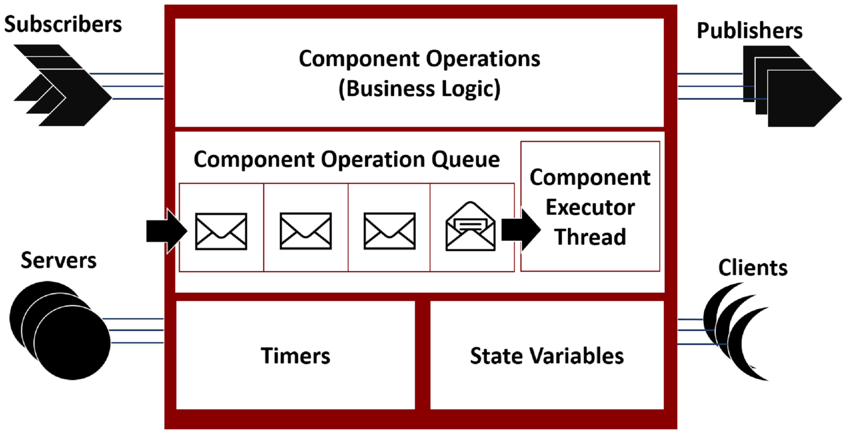
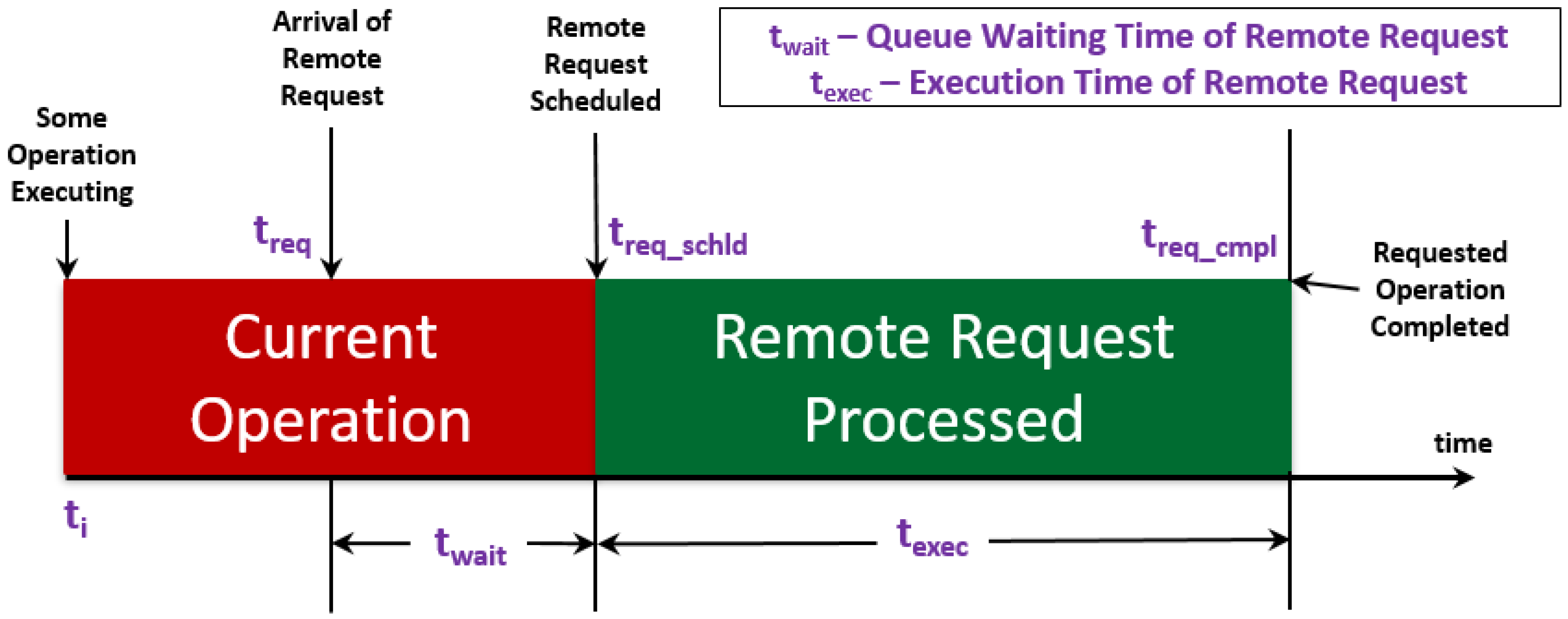
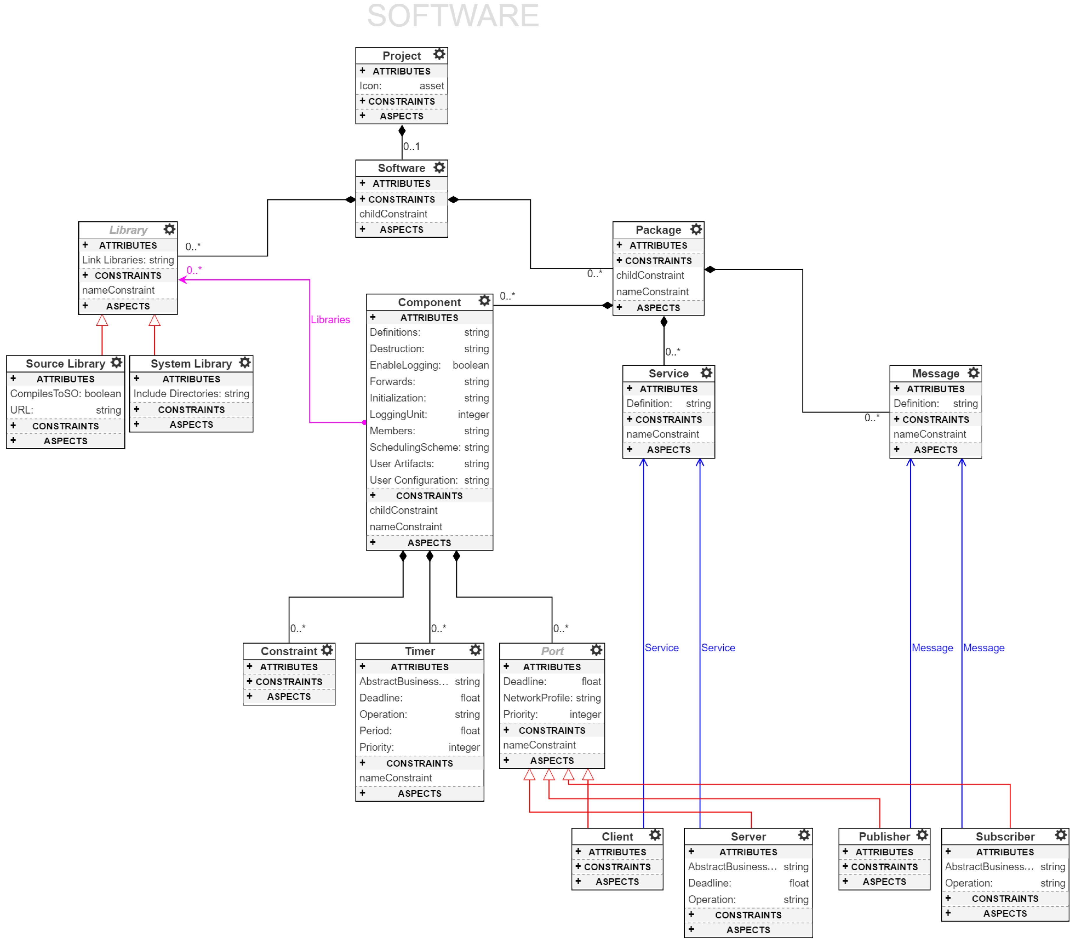
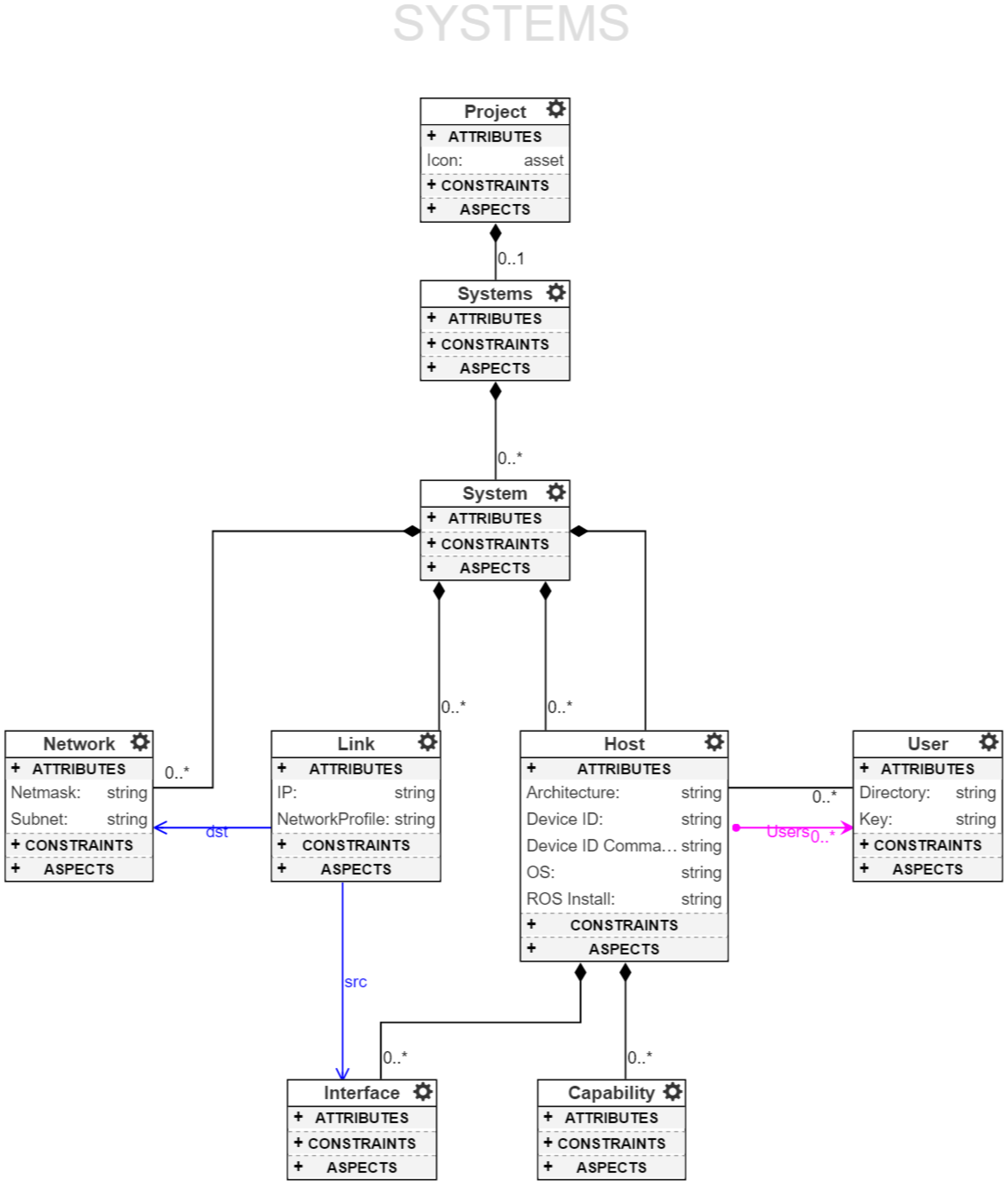
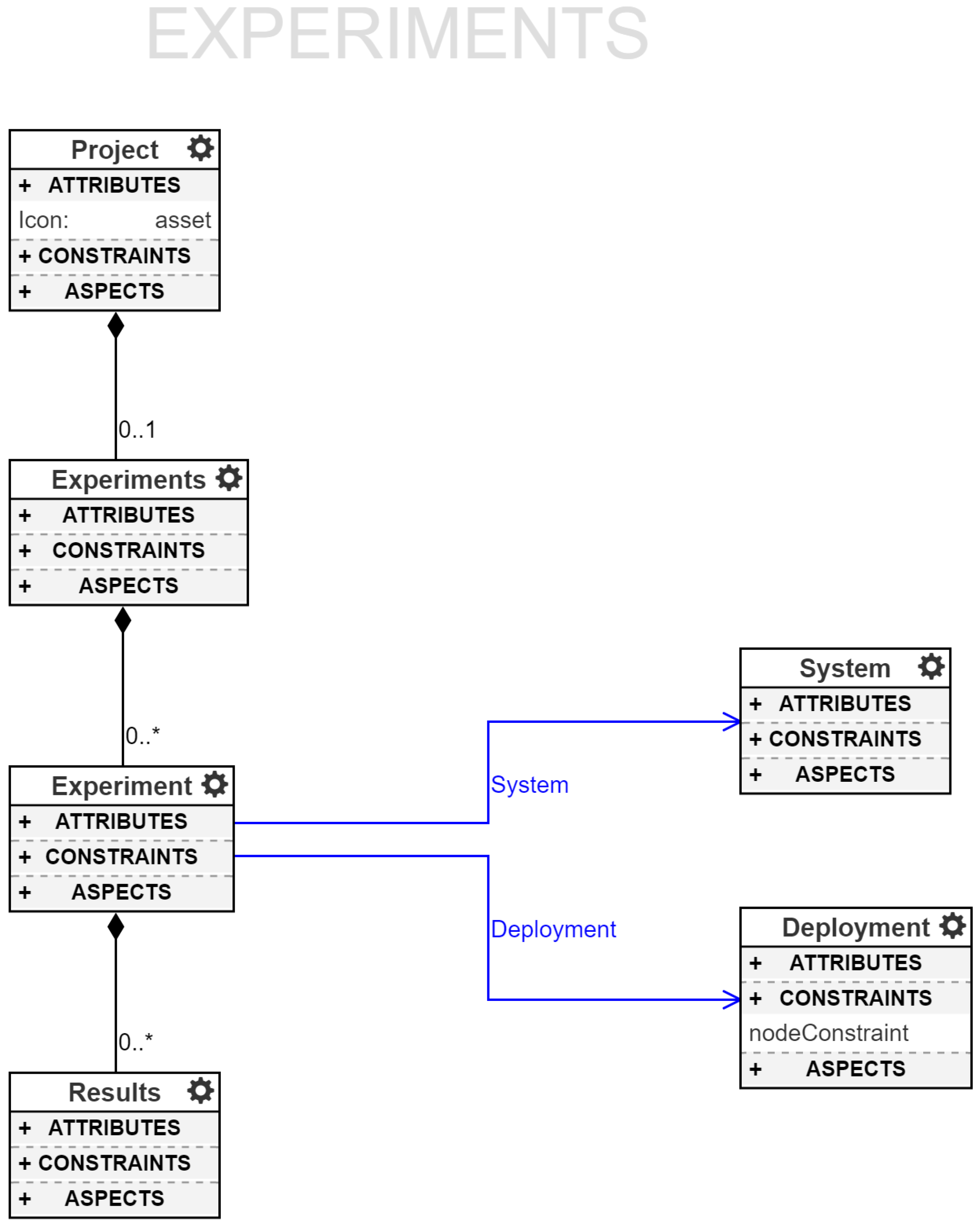
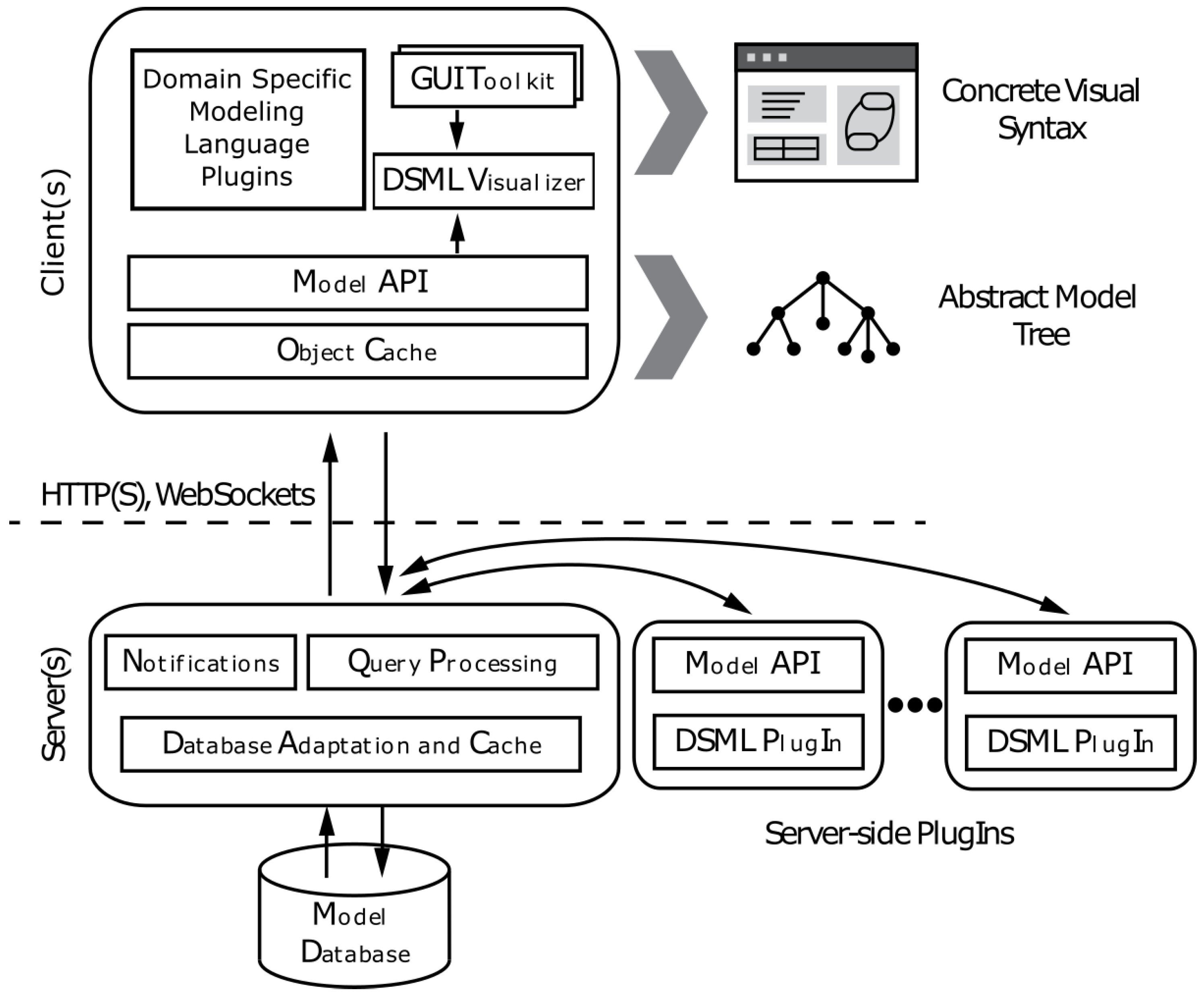
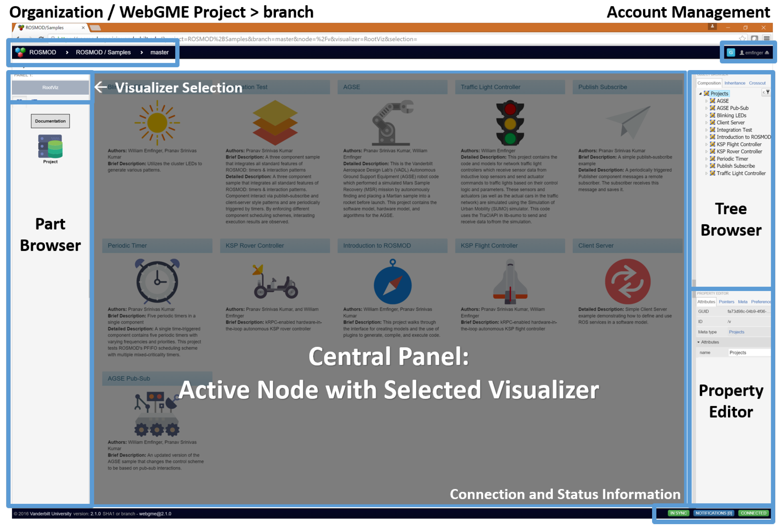
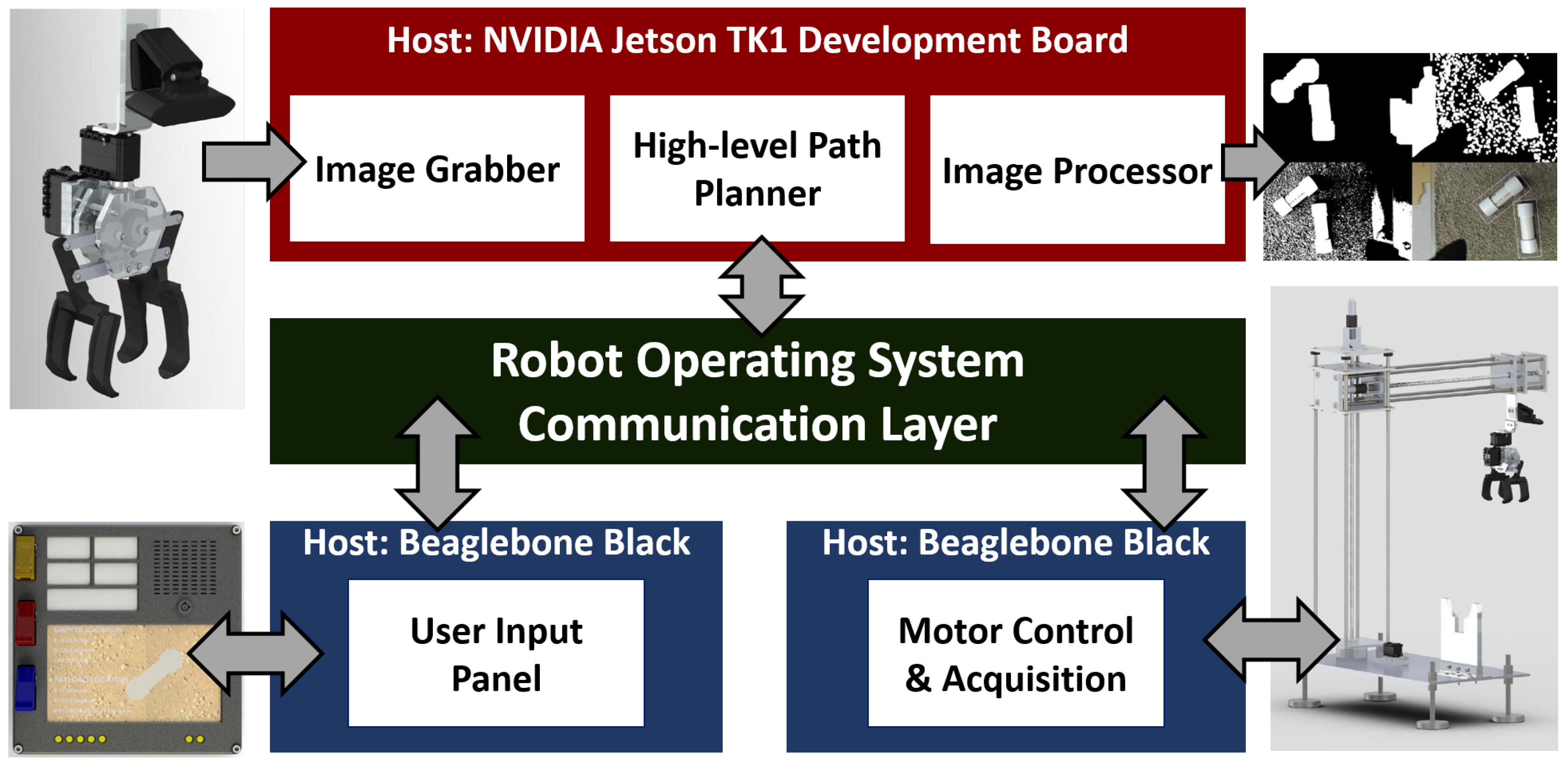
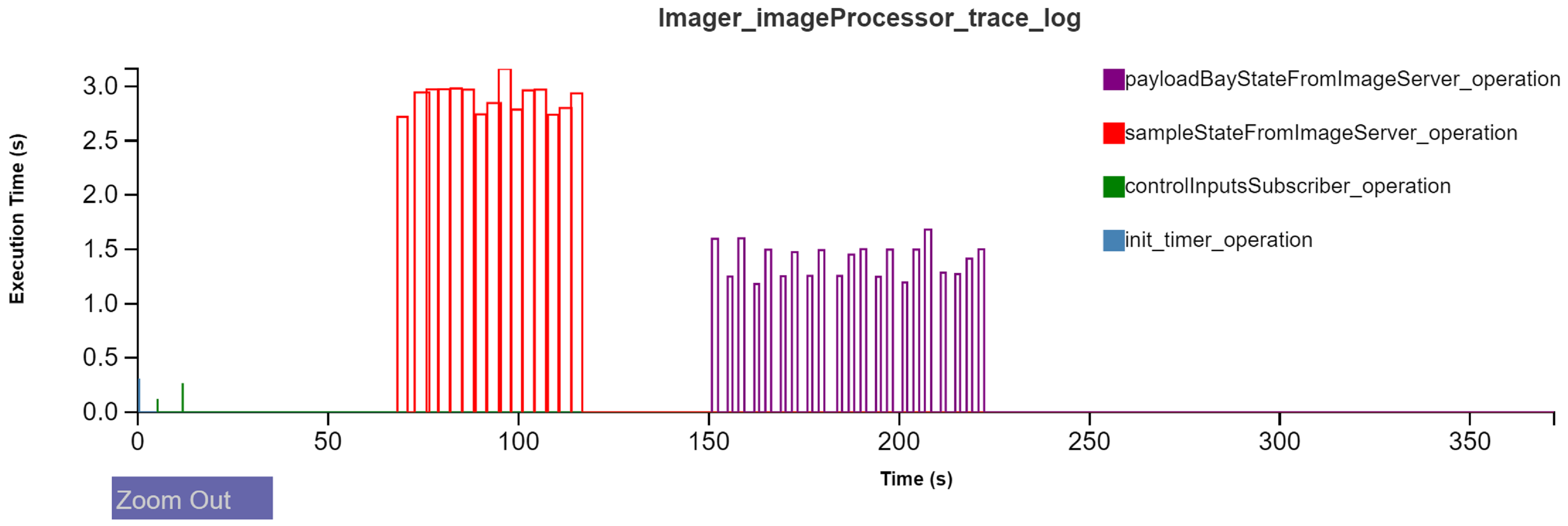
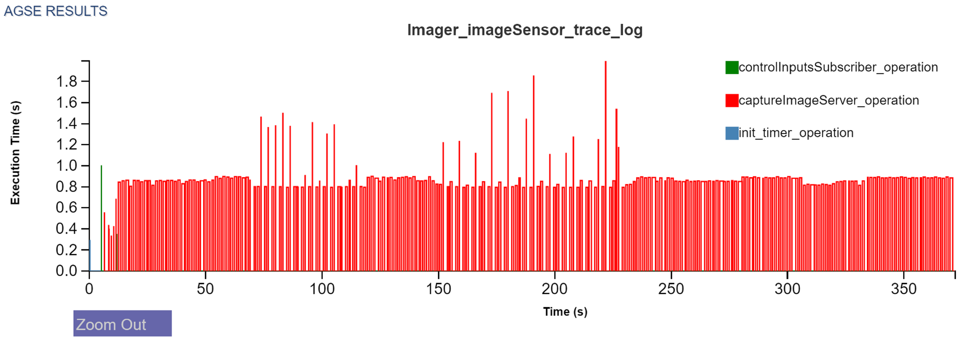
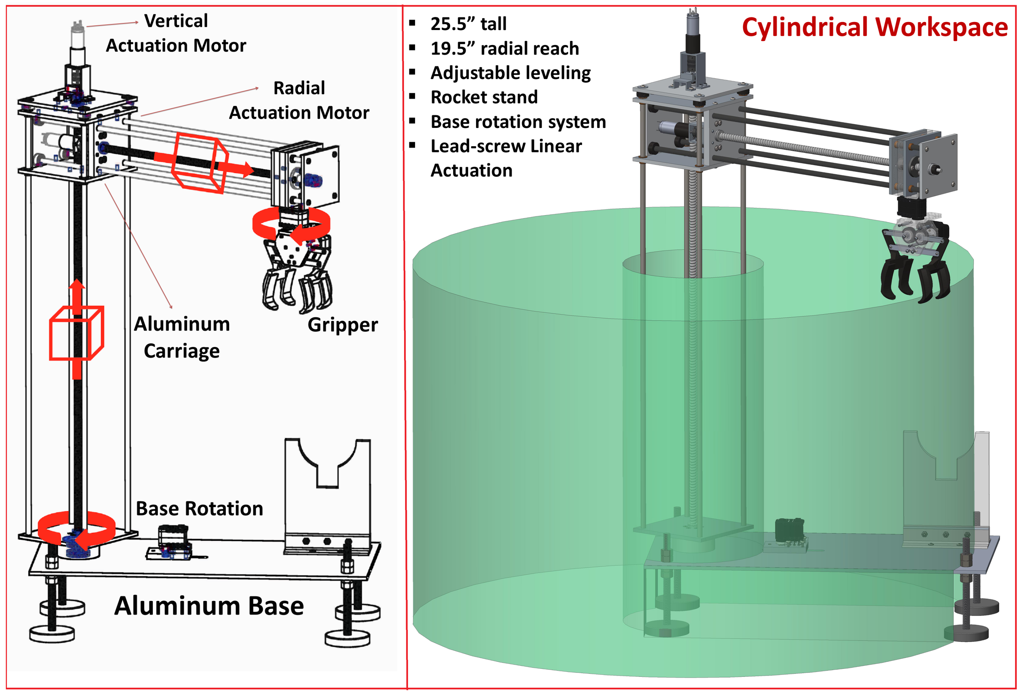
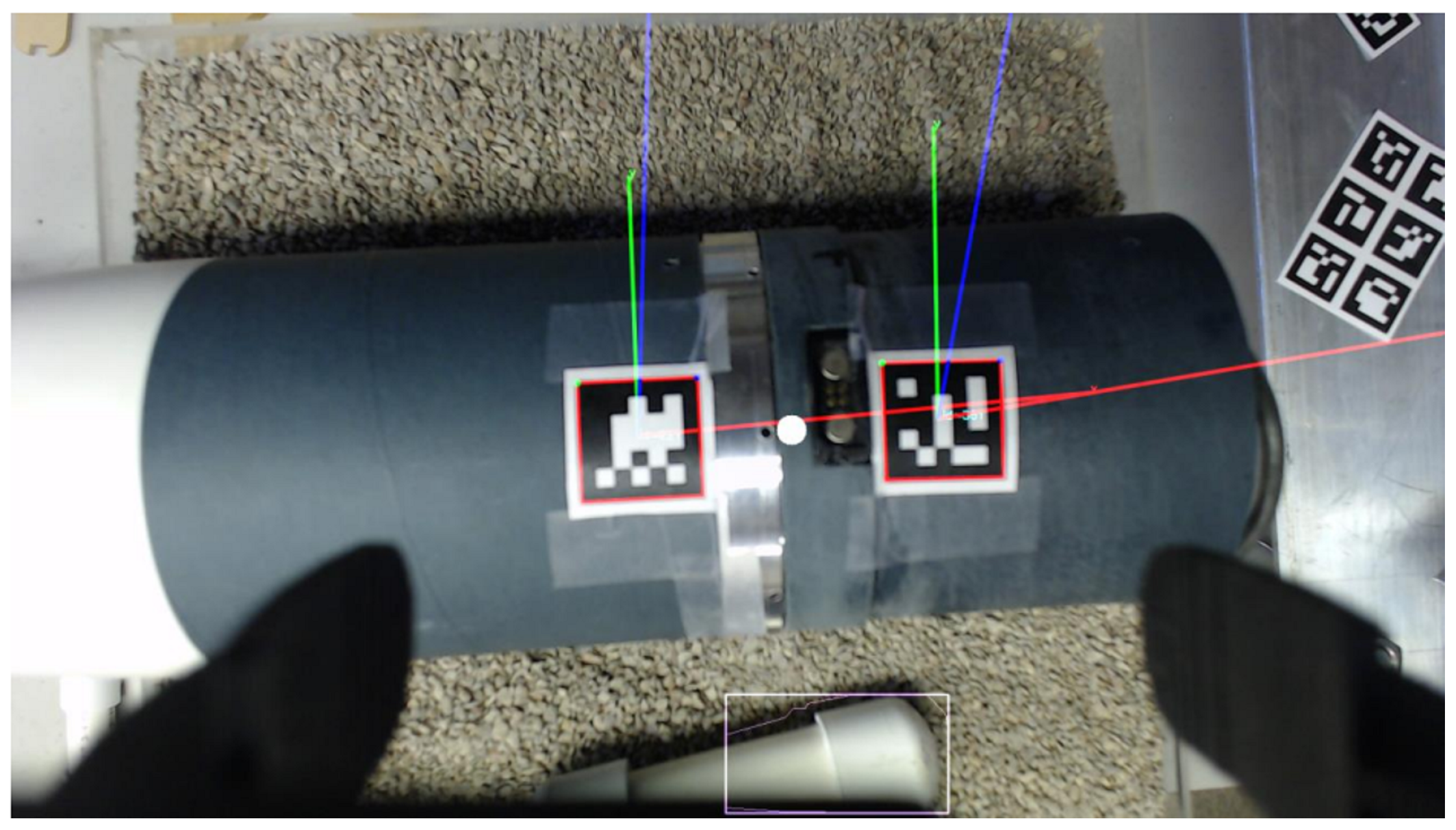