Article

Modelling and Daisy Chaining Control Allocation of a Multirotor Helicopter with a Single Tilting Rotor

Robotics and Mechatronics Research Laboratory, Department of Mechanical and Aerospace Engineering, Monash University, Clayton, VIC 3800, Australia
*
Author to whom correspondence should be addressed.
Electronics 2016, 5(4), 81; https://doi.org/10.3390/electronics5040081
Submission received: 7 October 2016 / Revised: 7 November 2016 / Accepted: 15 November 2016 / Published: 23 November 2016
(This article belongs to the Special Issue Unmanned Aerial Systems/Vehicles (UAS/V) and Drones)

Abstract

:
This paper presents the development and implementation of a single tilting rotor multirotor helicopter. A single tilting rotor multirotor helicopter is proposed that allows for decoupled lateral acceleration and attitude states. A dynamics model of the proposed multirotor helicopter is established to enable control system development. A control system architecture and daisy chaining-based control allocation scheme is developed and implemented. The control architecture facilitates the control of decoupled lateral accelerations and attitudes. Further, a computational and experimental analysis is undertaken and offers evidence that the proposed multirotor helicopter and control system architecture enables the multirotor helicopter to achieve lateral accelerations without requiring attitude actuation.

Graphical Abstract

1. Introduction

Unmanned aerial vehicles have rapidly gained in popularity in recent years [1,2,3]. In particular, there has been significant interest in unmanned multirotor helicopters [4,5,6,7,8,9,10,11]. This is primarily due to the wide range of applications and to their mechanical simplicity and durability. However, the mechanical simplicity of multirotor helicopters does come at a cost: traditional multirotor helicopters are underactuated. In particular, only four of the six degrees-of-freedom are controllable. Multirotor helicopters are capable of tracking desired attitudes, headings and accelerations in the body-fixed vertical direction. Multirotor helicopters cannot achieve accelerations in the body-fixed horizontal plane. This results in a coupling between multirotor helicopters’ attitude and acceleration. This underactuation places fundamental restrictions on the ability to perform tasks requiring manipulation of the surrounding environment. It also necessitates the use of complex mechanical componentry if a payload is to remain at a given attitude independent of the desired movement of the multirotor helicopter.
In an effort to overcome this limitation, several approaches have been proposed. An aerial vehicle with three ducted fans mounted on gimbals is under investigation by Jayakody [12] and Yuan [13]. The gimbals allow the thrust produced by the ducted fans to be directed with respect to the body of the aircraft, allowing for horizontal accelerations independent of attitude. Another approach has been presented by Cetinsoy et al. [14]. Their platform consists of a multirotor helicopter with sub-rotor control surfaces. The control surfaces allow the down-wash from the rotors to be directed, thus producing a lateral component in the resultant force. Further, tilt-rotor actuation has been investigated by Kendoul et al. [15] and Ryll et al. [16]. Tilt-rotor actuation involves mounting the rotors of traditional multirotor helicopters on gimbals, thus allowing the resultant thrust to be vectored as in the approach by Jayakody and Yuan [12,13]. Finally, helicopters utilise swash-plates to allow cyclic-pitch rotor blade actuation [17]. The cyclic-pitch of a rotor affects the moment produced by the rotor about axes perpendicular to the rotor’s axis of rotation. The cyclic-pitch further causes the thrust produced by the rotor to be vectored with respect to the body of the multirotor helicopter. Therefore, cyclic-pitch allows lateral accelerations to be achieved. However, changes to a rotor’s cyclic-pitch induce a secondary change in attitude towards the direction of thrust produced.
Drawing inspiration from research into tilt-rotor-equipped multirotor helicopters, in this paper, a minimal actuation concept that aims to achieve the same result is proposed. Rather than allowing all rotors to tilt, only a single tilting rotor is included on an otherwise traditional multirotor helicopter. The proposed aircraft is mechanically simpler than a tilt-rotor multirotor helicopter, as only a single additional actuator is required. The proposed multirotor helicopter can achieve control of five degrees-of-freedom; allowing for horizontal accelerations that are independent of attitude. To achieve this, a daisy chaining-based control allocation methodology is proposed. This control allocation methodology takes full advantage of the proposed multirotor helicopter by prioritising maintaining the desired attitude when manoeuvring and utilising changes in attitude only when absolutely necessary.
The remainder of this paper is structured as follows. In Section 2, the dynamics model of the single tilt-rotor multirotor helicopter is developed. An analysis is conducted to determine the available control bandwidth in Section 3. The proposed daisy chaining-based control allocation methodology is detailed in Section 4. Computational and experimental analyses of the single tilt-rotor multirotor helicopter and control system architecture are presented in Section 5 and Section 6, respectively. Finally, concluding remarks are given in Section 7.

2. Multirotor Helicopter Dynamics Model

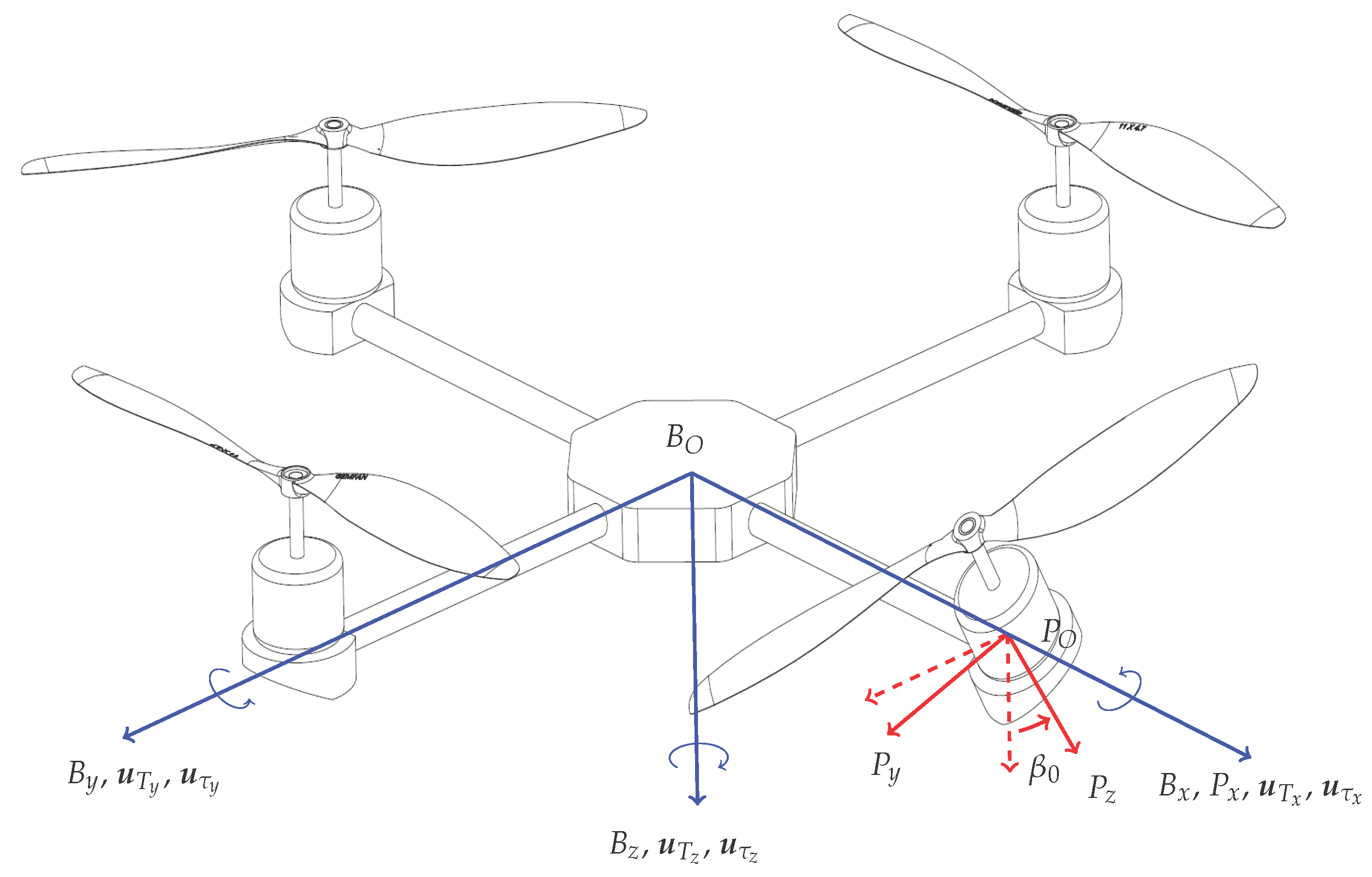
The multirotor helicopter proposed in this research consists of two rigid bodies: the multirotor helicopter body, B, which includes the non-tilting rotor groups; and the tilting rotor group, P. The tilting rotor group includes the gimbal, the motor driving the tilting rotor and the rotor itself. The tilting rotor is constrained to only rotate about the arm to which it is attached. A schematic of the proposed multirotor helicopter is presented in Figure 1. In this section, the dynamics model of this multirotor helicopter is developed. The nomenclature utilised in this section is presented in Table 1.
A right-hand coordinate frame F B , with origin F B O , is attached to the centre of B as in Figure 1. Additionally, a coordinate frame F P is attached to the tilting rotor group. The origin of F P , F P O , is positioned at the intersection of the axis about which the rotor group rotates and the axis about which the rotor itself rotates. Without loss of generality, it is assumed that the tilting rotor is positioned along the x axis of F B . An inertial coordinate frame is defined as F E . The orientation of F B with respect to F E is given by the attitude quaternion, q B E . Likewise, the orientation of F P with respect to F B is given by q P B .
The following assumptions are made:
  • The multirotor helicopter body is rigid and symmetrical
  • F B O and the centre of mass of the multirotor helicopter coincide
  • The rotors are rigid
  • The multirotor helicopter is operating in the vicinity of the hover condition
  • The aerodynamic drag force on the multirotor helicopter body is negligible
Under these assumptions, the dynamics model of the multirotor helicopter can be derived using the Newton–Euler formalism.
The angular velocity of the tilting rotor in F P , ω 0 , is given by:
0 ω 0 = q ¯ P B 0 ω B q P B + 0 β ˙ 0 ω 0
where q ¯ indicates the conjugate of quaternion q; ω B is the angular velocity of F B with respect to F E ; β is the angle between F B z and F P z (the subscript z indicates the z axis); and ω 0 is the angular velocity of the tilting rotor about F P z . Differentiating this expression results in the angular acceleration of the tilting rotor in F P , which is given in the following equation.
0 ω ˙ 0 = 0 ω B P × ω B + q ¯ P B 0 ω ˙ B q P B + 0 β ¨ 0 ω ˙ 0
In Equation (2), ω B P is the angular velocity of F B with respect to F P .
The torque produced by the tilting rotor, τ 0 , is given by:
τ 0 = I R 0 ω ˙ 0 + ω 0 × I R 0 ω 0 τ e x t 0
where τ e x t 0 is the external torque applied to the tilting rotor. τ e x t 0 is primarily due to a counter-rotating torque about F P z caused by the air drag [17] and is typically considered to be of the following form in normal operating conditions (see [8,18,19], for example),
τ e x t i = 0 0 k τ , i ω i ω i T
where the subscript i indicates the rotor number; and k τ is a constant determined by the rotor size and profile.
Similarly, the torque produced by each of the non-tilting rotors can be expressed as:
τ i = I R i ω ˙ i + ω i × I R i ω i τ e x t i i 1 , 2 , 3
where:
ω i = ω B + 0 0 ω i T .
The torque on the multirotor helicopter in F B , τ B , can be described as:
0 τ B = 0 I B ω ˙ B + ω B × I B ω B + q P B 0 τ 0 q ¯ P B + i = 1 3 0 τ i .
The torques produced by the multirotor helicopter are due to the thrusts produced by each of the rotors and are given by:
0 τ B = 0 L P B × q P B 0 T 0 q ¯ P B + i = 1 3 0 L P i B × T i
where L P B is the vector from F B to F P ; T 0 is the thrust of the tilting rotor in F P ; L P i B is the vector from F B along each of the arms of the multirotor helicopter to the axis of rotation of the i-th rotor; and T i is the thrust vector of the i-th rotor in F B . It should be noted that, as for Equation (4), it is typical to assume T takes the following form for a fixed-pitch rotor in normal operating conditions,
T i = 0 0 k T , i ω i 2 T
where k T , i is a constant determined by the rotor size and profile.
The translational dynamics of the multirotor helicopter are derived using a force balance and are presented in the following equation.
m 0 p ¨ = m 0 g + q ¯ B E q ¯ P B 0 T 0 q P B + i = 1 3 0 T i q B E
In Equation (10), m is the mass of the multirotor helicopter; p is the position vector of F B relative to F E ; and g is the gravity vector in F E .
The complete dynamics model of the multirotor helicopter with single tilting rotor is given by Equations (1) to (10).

3. Control Bandwidth Analysis

One of the primary constraints when implementing a single tilting rotor is that the lateral thrust produced by the tilting rotor cannot be balanced by vectoring thrust produced by another rotor. Instead, the resulting moment about F B z must be balanced by torque produced by the non-tilting rotors. As the torque produced by the rotors is an order of magnitude less than the thrust produced, this constraint requires careful consideration.
To characterise the available control bandwidth, the multirotor helicopter dynamics developed in the previous section can be simplified into Equations (11) to (16).
I B + i = 0 3 I R i ω ˙ B = ω B × I B ω B G τ + u τ
m 0 p ¨ = m 0 g + q ¯ B E 0 u T q B E
0 G τ = q P B 0 G τ q ¯ P B + 0 G τ
G τ = I R 0 ω B P × ω B + β ¨ 0 ω ˙ 0 T + ω 0 × I R 0 ω 0
G τ = i = 1 3 ( 1 ) i I R i 0 0 ω ˙ i T + ω i × I R i ω i
u T u τ = 0 0 0 0 k T sin ( β ) 0 0 0 k T cos ( β ) k T k T k T 0 l k T 0 l k T l k T cos ( β ) k τ sin ( β ) 0 l k T 0 l k T sin ( β ) + k τ cos ( β ) k τ k τ k τ ω 0 2 ω 1 2 ω 2 2 ω 3 2
In (16), l is the distance from F B 0 to the axis each rotor rotates about; β and w i 2 i [ 0 , 3 ] are the control inputs, and u T and u τ are the virtual control inputs to the dynamics system. The process for setting the control inputs given a set of virtual control inputs is referred to as control allocation. Adding the virtual control input abstraction allows for simpler outer loop controller design, as the details of control allocation do not have to be considered.
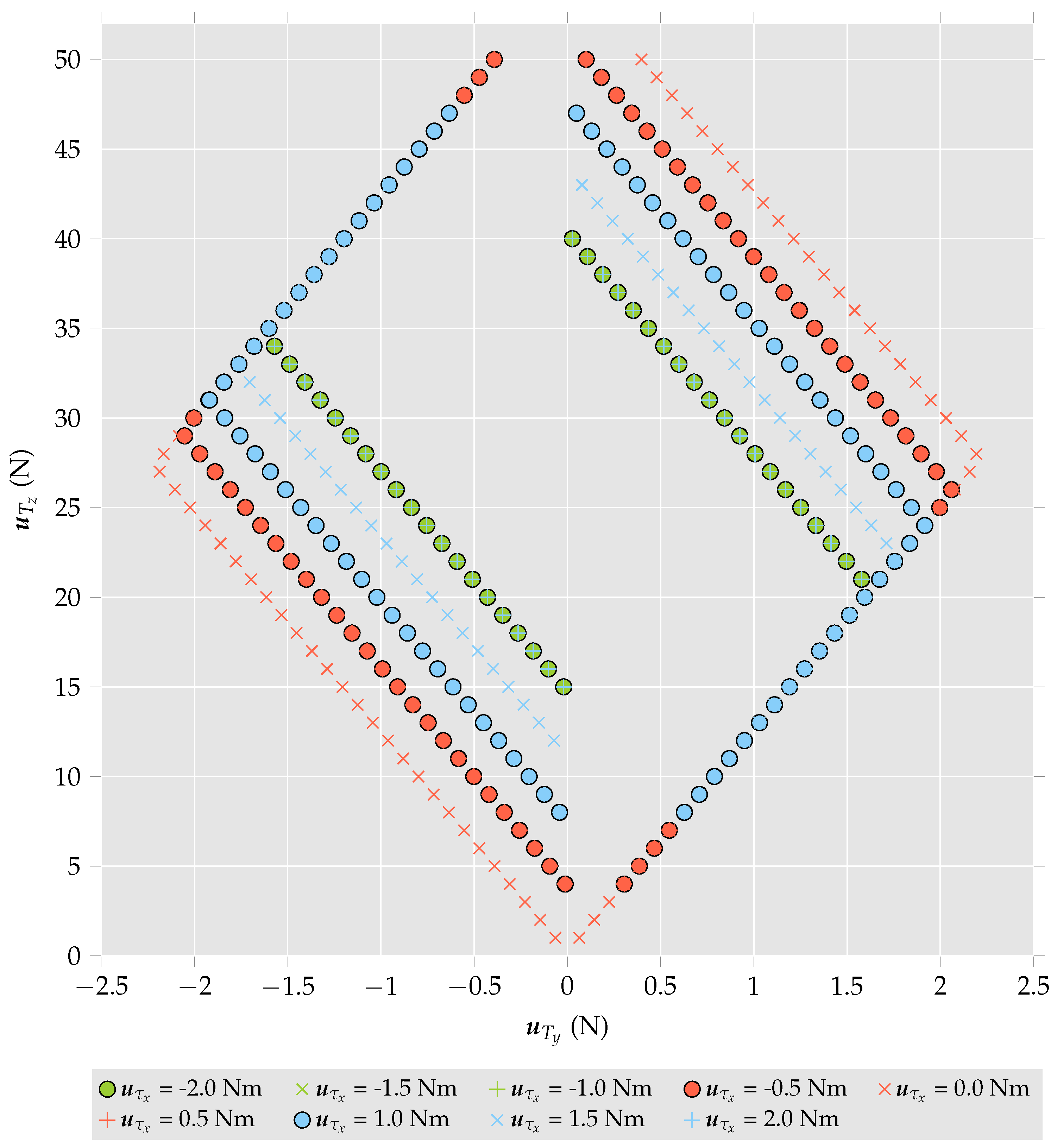
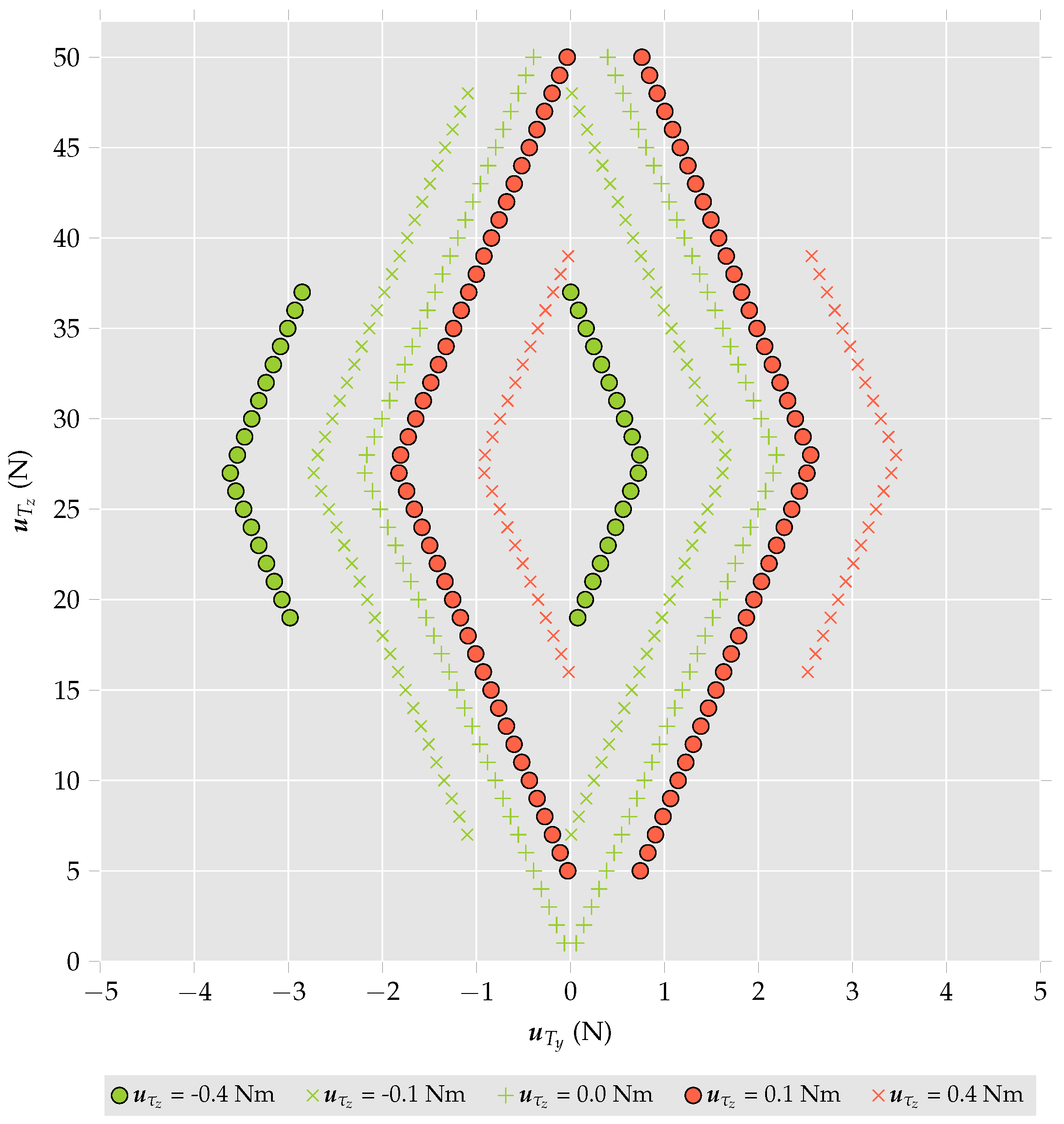
The control bandwidth can be characterised by an analysis of Equation (16). In particular, given control input constraints, the maximum and minimum achievable lateral forces, u T y , that can be generated can be determined as a function of required vertical force, u T z , and torques, u τ 
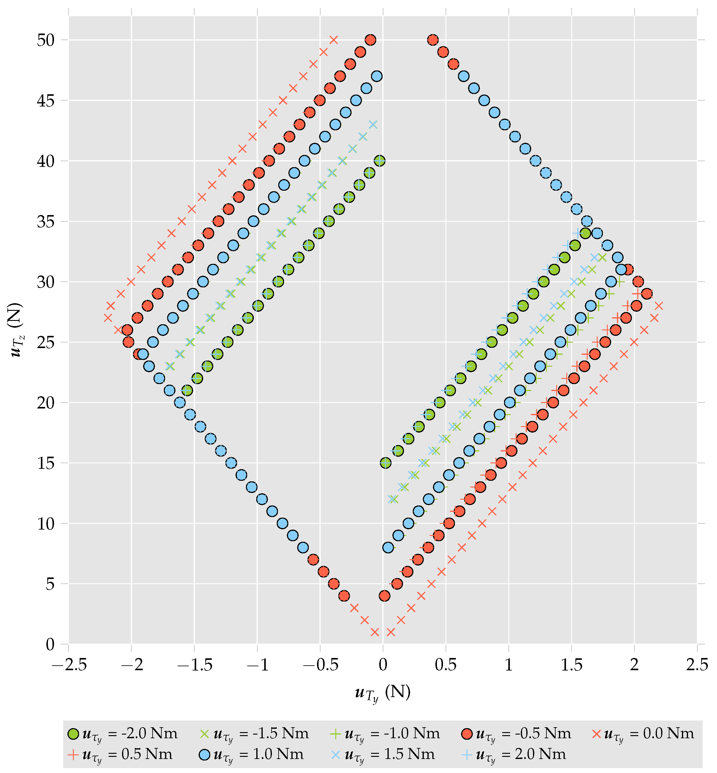
. The results presented in Figure 2, Figure 3 and Figure 4 were calculated by setting u T z and u τ and increasing or decreasing u T y until the system could no longer be solved to satisfy the control input constraints. The data points represent the maximum and minimum values of u T y for a given set of u T z and u τ . The parameters k T , k τ and l are presented in Table 2, along with the control input constraints and additional multirotor helicopter parameters. It should further be noted that these results are valid for operating conditions sufficiently close to the hover condition where assumptions made in Equations (4) and (9) are valid.
To demonstrate how the addition of a single tilting rotor affects the control bandwidth of the multirotor helicopter, consider Figure 2. In this case, u τ y = u τ z = 0 Nm. Consider a case where u T z and u T y are initially 40 N and 0 N, respectively. Referring to the figure, it is observed that under these conditions, the multirotor helicopter is able to generate ±2 Nm of torque about the x axis. If the desired u T y is increased to 0.5 N and the other desired control inputs remain the same, the torque the multirotor helicopter can generate is reduced to ± 1 Nm. If the desired u T y is increased further to 1 N, the magnitude of torque the multirotor helicopter can generate is reduced to <0.5 Nm. If u T y continues to be increased, the system cannot be solved for any value of u τ x once u T y reaches 1.3 N. In this case, to solve for the desired values u T y and u τ , u T z has to be decreased.

4. Control System Architecture

The objective of the control system in this research is to maintain the multirotor helicopter at a level attitude while allowing horizontal accelerations. However, the control system should also be capable of changing the attitude of the multirotor helicopter in response to external disturbances or excessive commanded horizontal accelerations. To this end, a daisy chain control methodology is implemented. This method assumes a hierarchy of control effectors and does not utilise an available control effector until all higher priority control effectors become saturated [20]. For this research, the tilting rotor will be assigned the highest priority when tracking commanded horizontal accelerations. The attitude of the multirotor helicopter will only be affected when the tilting rotor cannot supply the required control bandwidth.

4.1. Position Control

To calculate the translational virtual control inputs, u T , a proportional-integral-derivative (PID) controller is utilised as follows,
u PID = k P ( p p d ) + k I 0 t ( p p d ) d t k D p ˙ d + u FF
where u PID is the input in F E from the PID controller; k P , k I and k D are the proportional, integral and derivative gains, respectively; and u FF is the feed-forward control input and is given by:
u FF = g .
u T can then be calculated by transforming u PID into F B using the current multirotor helicopter attitude and heading as follows:
0 u T = q B E 0 u PID q ¯ B E .

4.2. Control Allocation and Attitude Control

Having calculated u T , the tilting rotor tilt and the rotor angular velocities must be calculated. From Equation (16), it can be seen that the first element of u T cannot be non-zero. Therefore, it is omitted from the following control allocation, and u T is replaced with u T = u T y u T z T . To map the virtual control inputs to the physical control inputs, Equation (16) is linearised about β 0 , which results in:
u T u τ = A B C D ω 0 2 δ β ω 0 2 ω 1 2 ω 2 2 ω 3 2
where:
A = k T cos ( β 0 ) k T sin ( β 0 ) k T sin ( β 0 ) k T cos ( β 0 ) ; B = 0 0 0 k T k T k T ; C = 0 0 l k T sin ( β 0 ) k τ cos ( β 0 ) l k T cos ( β 0 ) k τ sin ( β 0 ) l k T cos ( β 0 ) k τ sin ( β 0 ) l k T sin ( β 0 ) + k τ cos ( β 0 ) ; D = l k T 0 l k T 0 l k T 0 k τ k τ k τ ;
and δ β is some perturbation in β away from β 0 .
As the multirotor helicopter is operating at about a zero attitude, it is initially assumed that u τ is negligible. This assumption allows Equation (20) to be reduced as follows,
u T = A B D 1 C ω 0 2 δ β ω 0 2 = A 11 A 12 A 21 A 22 ω 0 2 δ β ω 0 2
where:
A 11 = k T cos ( β 0 ) ; A 12 = k T sin ( β 0 ) ; A 21 = ( k T 2 l k τ 2 k τ l ) cos ( β 0 ) 4 k T sin ( β 0 ) ; A 22 = ( k T 2 l k τ 2 k τ l ) sin ( β 0 ) + 4 k T cos ( β 0 ) .
δ β and a preliminary estimate of ω 0 2 are therefore given by Equations (22) and (23), respectively.
δ β = A 22 u T y A 12 u T z A 11 u T z A 21 u T y
ω 0 ,   estimate 2 = 1 A 11 A 22 A 12 A 21 ( A 11 u T z A 21 u T y )
It should be noted that the denominator in Equation (23) is non-zero, and the denominator in Equation (22) is only zero if ω 0 ,   estimate 2 is zero.
An estimate of the achievable horizontal control input can then be calculated as:
u T y ,   estimate = k T sin ( β 1 ) ω 0 ,   estimate 2
where:
β 1 = β 0 + δ β ;
and it is enforced that β min β 1 β max and ω 0 ,   min ω 0 ,   estimate ω 0 ,   max .
Applying the daisy chain principle, the residual of the required control input in F E , u residual is calculated as:
0 u residual = 0 u PID q ¯ B E 0 0 u T y ,   estimate 0 q B E .
To achieve the residual of the desired control input, the attitude of the multirotor helicopter must be utilised. To this end, the minimum angle rotation to achieve u residual , q B ,   desired E is calculated as follows [21],
q B ,   desired E = 1 + u ^ residual T T u ^ residual × T 1 + u ^ residual T T u ^ residual × T 2 ;
where u ^ indicates the unit vector of vector u ; and:
T = 0 0 1 T .
The following equation can then be used to find the error between the current attitude and the desired attitude, q B ,   error E :
q B ,   error E = q B ,   desired E q ¯ B E .
Further, the time-derivative of q B ,   error E is calculated as:
q ˙ B ,   error E = 1 2 q B ,   error E 0 ω B .
The attitude is regulated utilising a PD2 feedback control proposed by Tayebi et al. [8]. The two derivative actions act on the body angular velocity and the derivative of the attitude error. The controller also includes a feed-forward term to negate the Coriolis torque. The PD2 control is:
u τ = ω B × I B ω B ( T 3 + T 2 T 1 ) q B ,   error E T 2 ω B I B T 1 q ˙ B ,   error E
where T 1 is a 3 × 3 symmetric positive definite matrix; and T 2 and T 3 are 3 × 3 diagonal positive definite matrices.
Finally, as u T z , u τ and δ β have been calculated, the rotor angular velocities can be calculated as follows:
ω 0 2 ω 1 2 ω 2 2 ω 3 2 = ( E T W E ) 1 E T W u T u τ
where W is a diagonal, positive-definite, pseudo-inversion weight matrix; and:
E = k T sin ( β 1 ) 0 0 0 k T cos ( β 1 ) k T k T k T 0 l k T 0 l k T l k T cos ( β 1 ) k τ sin ( β 1 ) 0 l k T 0 l k T sin ( β 1 ) + k τ cos ( β 1 ) k τ k τ k τ ,
thus completing the feedback control for the single tilt-rotor multirotor helicopter.

5. Computational Analysis

To characterise the performance of the single tilt-rotor multirotor helicopter, a computational model was developed. The parameters of the multirotor helicopter are presented in Table 2. In this computational analysis the dynamics model is updated at a rate of 10 kHz, and the control is performed at 200 Hz.
Initially, the multirotor helicopter is commanded to move in the y-direction at a rate of 1 m/s. After a period of 10 s, the multirotor helicopter is commanded to increase its velocity to 5 m/s. The complete motion is presented in Figure 5. The attitude of the multirotor helicopter during the manoeuvre is presented in Figure 6. Further, 
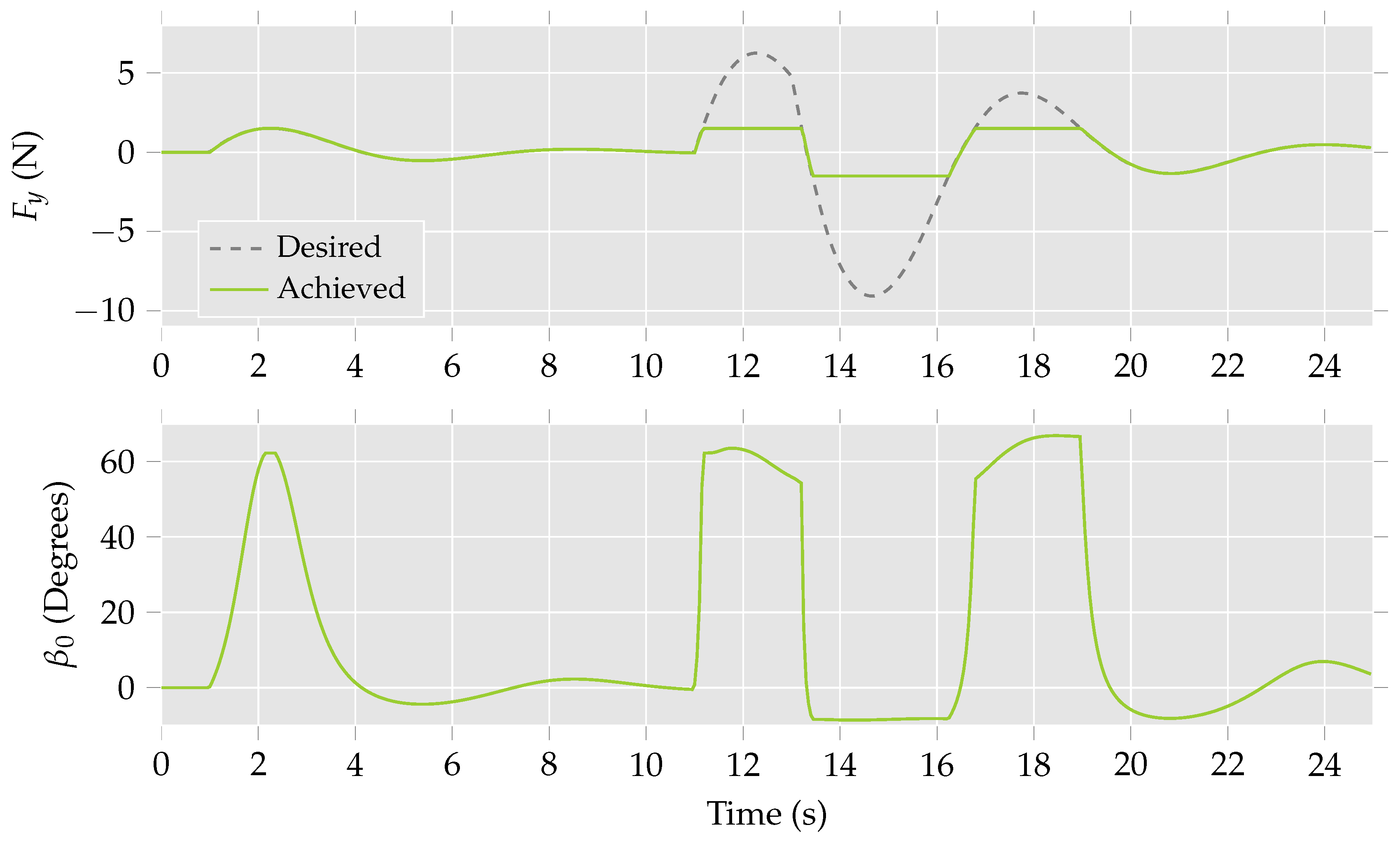
Figure 7 shows the achieved lateral force and the corresponding rotor tilt.
From Figure 7, it is observed that the entire desired lateral force for the initial stage of the manoeuvre can be achieved through actuating the tilting rotor only. This is reflected in Figure 6, as the roll remains unchanged despite the multirotor helicopter moving in the desired direction. During the second stage of the manoeuvre, it can be seen that actuating the only tilting rotor no longer produces the desired lateral force. Instead, the attitude of the multirotor helicopter must be utilised to achieve the desired motion. This is represented in Figure 6 as a change in the roll, ϕ, of the multirotor helicopter.

6. Experimental Analysis

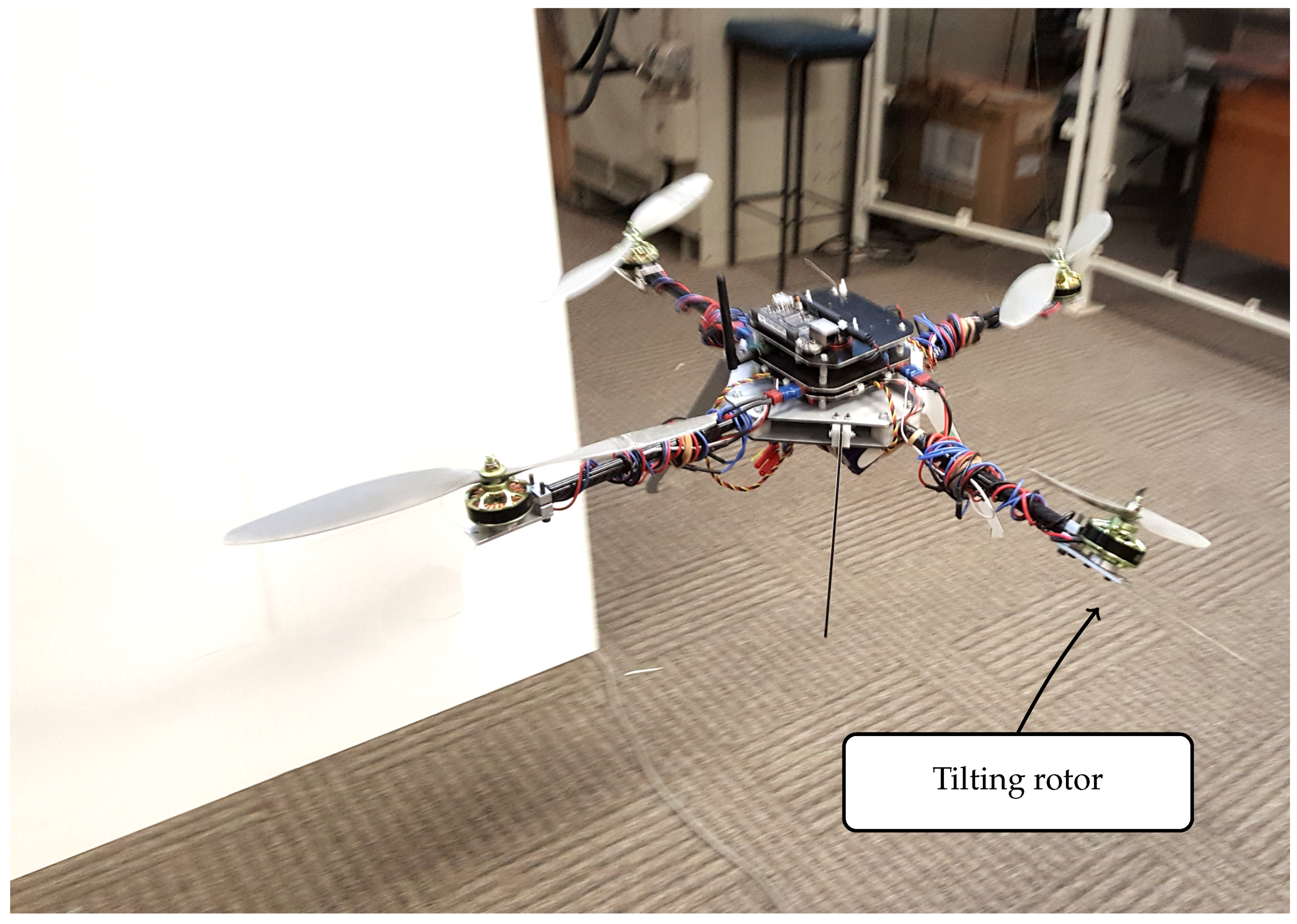
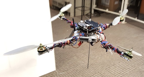
To validate the results obtained from the computational analysis in the previous section, an experimental analysis has been undertaken. To this end, an experimental research facility has been established. The research facility incorporates a single tilt-rotor multirotor helicopter. The multirotor helicopter is presented in Figure 8. The remainder of the research facility has been presented in previous work by the author [22] and includes a laser interferometry-based sensing and measurement unit to precisely record the position of the multirotor helicopter at a rate of 1000 Hz. Measurements from accelerometers, gyroscopes and magnetometers mounted onboard the multirotor helicopter are recorded at a rate of 200 Hz. The algorithm proposed in [23] is utilised to combine these sensor measurements to produce attitude estimates. The desired rotor angular velocities and rotor tilt angle are also updated a rate of 200 Hz. The PID and PD2 controller gains in Equations (17) and (29), respectively, were calculated utilising the Ziegler–Nichols step-response tuning methodology [24]. This methodology was chosen as the same set of tuning rules could be applied to multirotor helicopters with different rotor configurations, removing the effect of controller tunings from any comparisons drawn.
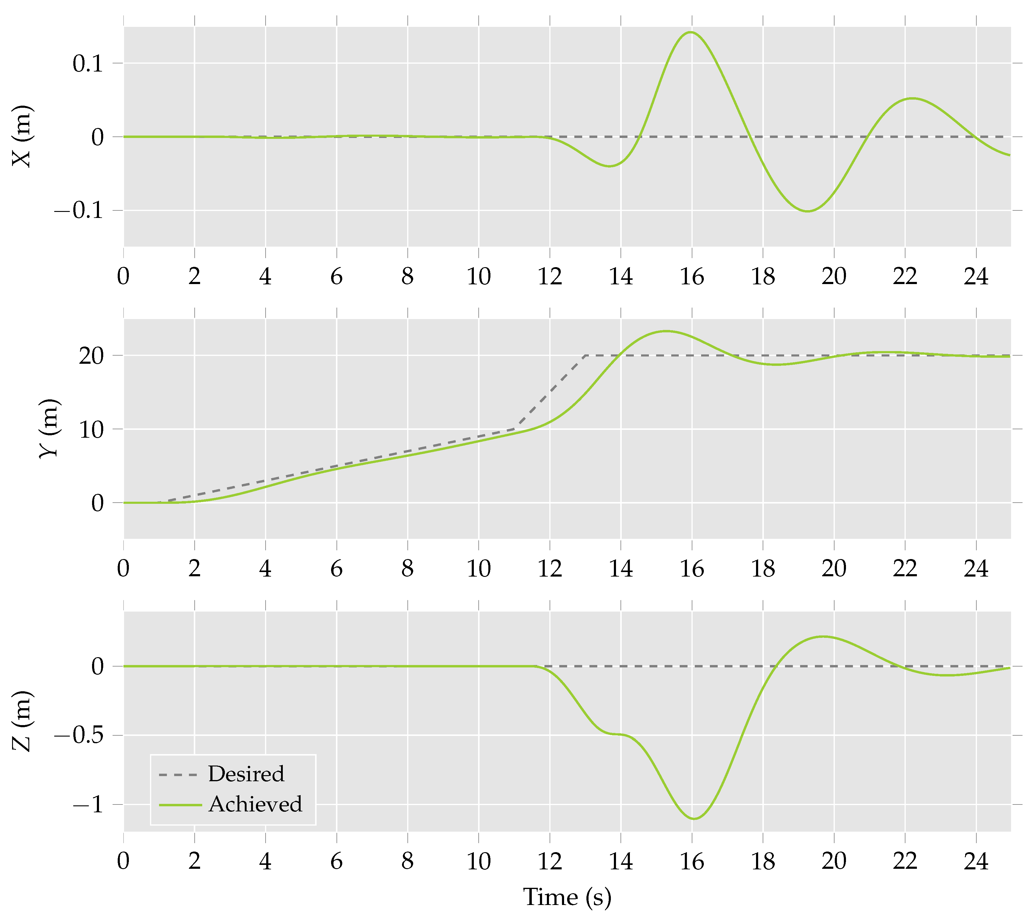
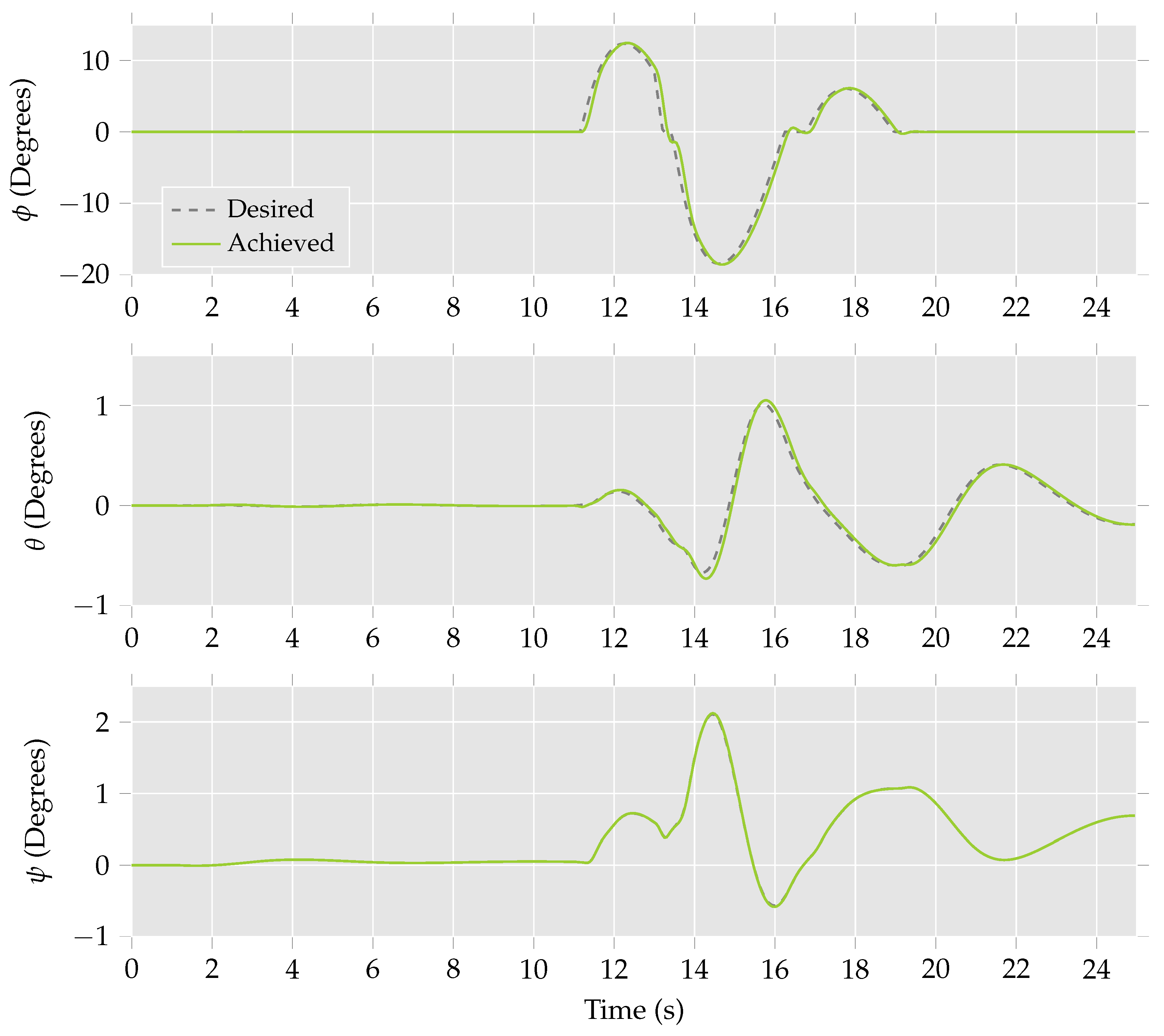
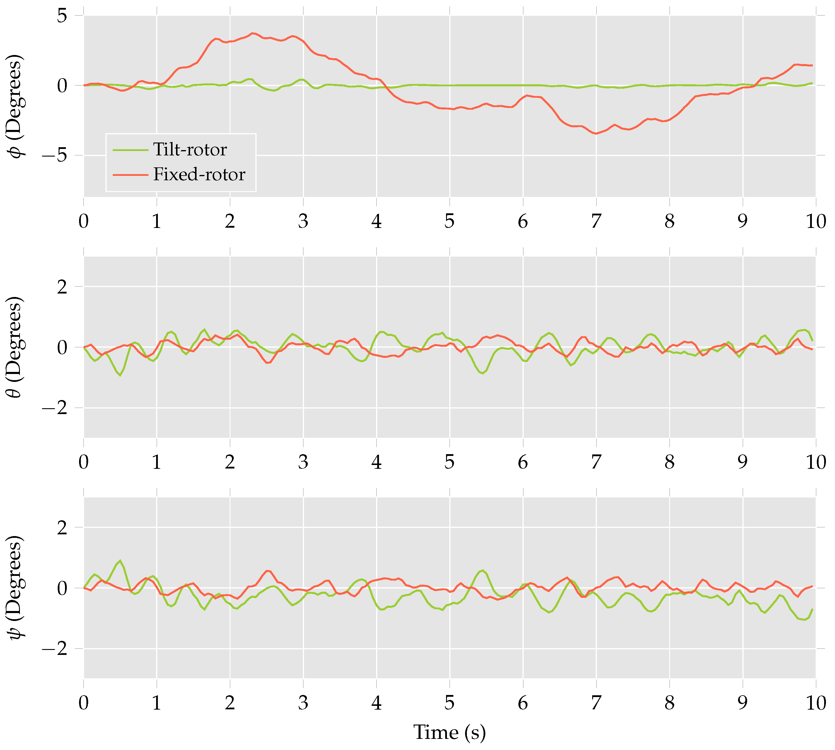
In the first experiment, the multirotor helicopter was commanded to move in the y-direction at 0 . 8 m/s. The measured position and estimated attitude of the multirotor helicopter during this manoeuvre are presented in Figure 9 and Figure 10, respectively. The experiment was repeated with the same multirotor helicopter with all four rotors fixed in the traditional positions, the results of which are also presented in the figures.
Referring to Figure 9, it is observed that the differences between the trajectories for the multirotor helicopter with a single tilt-rotor configuration and the fixed-rotor configuration are minimal. The most notable difference is the drift in the x-direction of the single tilt-rotor multirotor helicopter, which differs from the desired trajectory by 0 . 08 m. The corresponding drift of the fixed-rotor multirotor helicopter is only 0 . 015 m. The differences between the performance of the multirotor helicopter configurations is observed in Figure 10. Here, the fixed-rotor multirotor helicopter is required to roll up to 4 to achieve the desired trajectory. The multirotor helicopter in the single tilt-rotor configuration exhibits a maximum roll of only 0 . 5 .
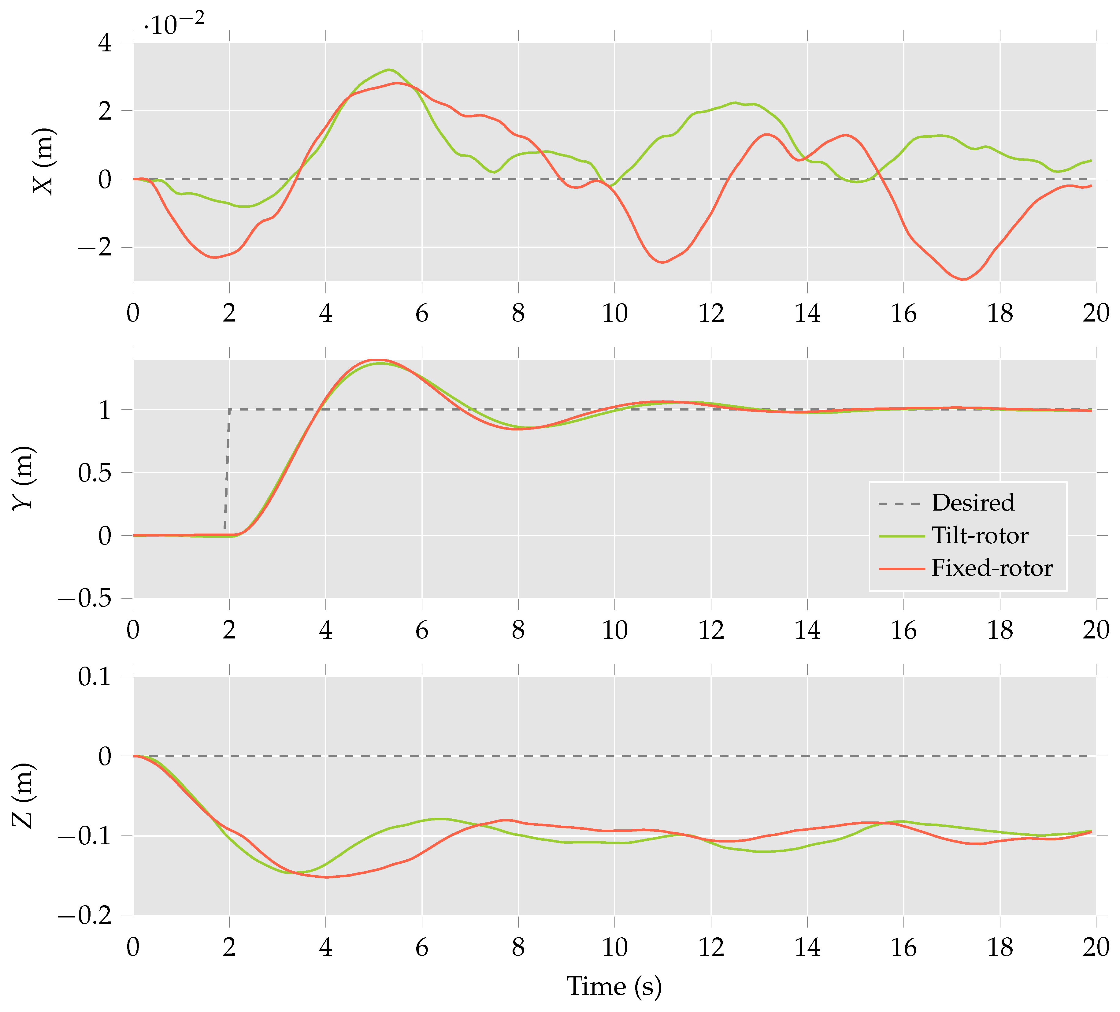
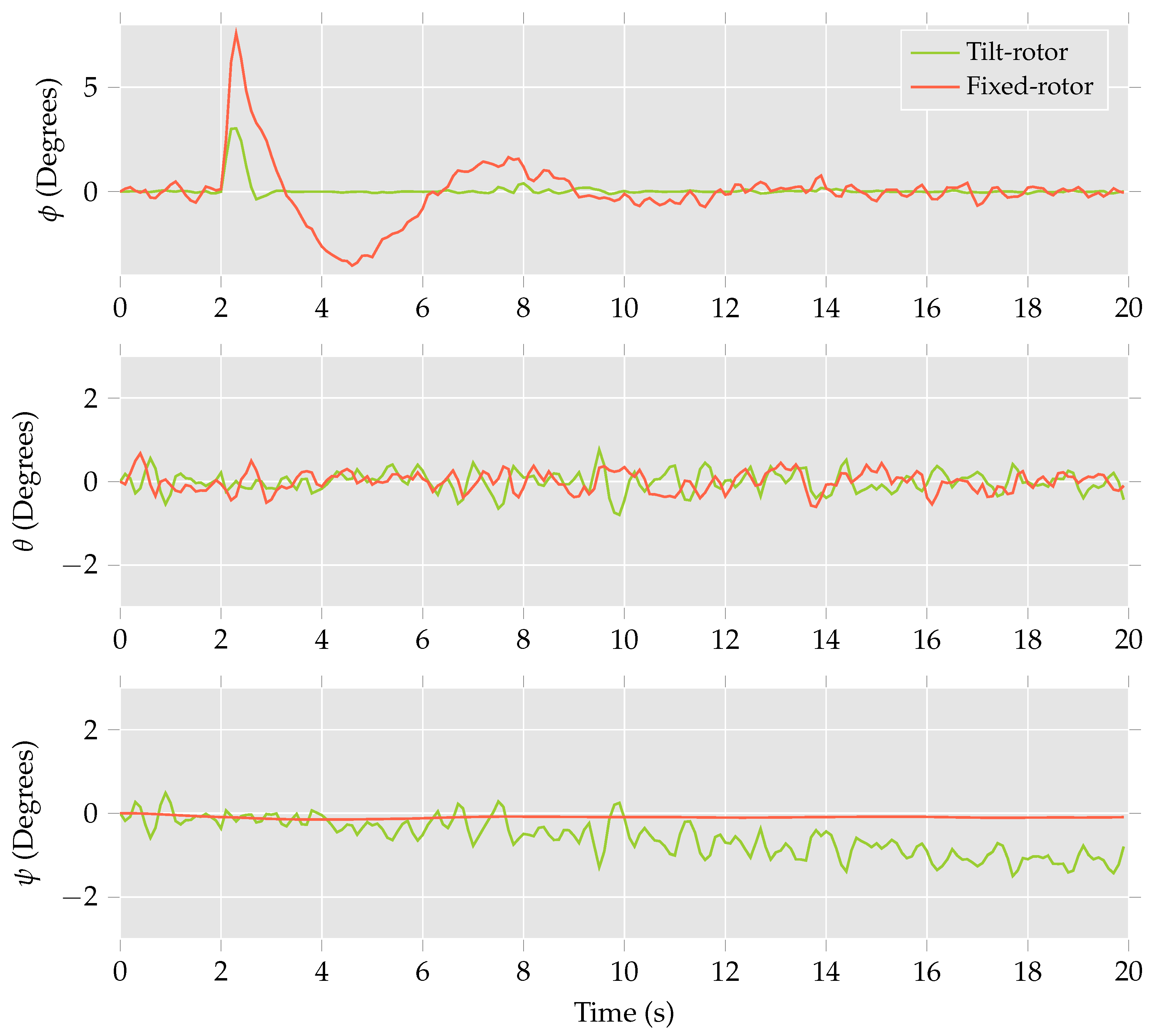
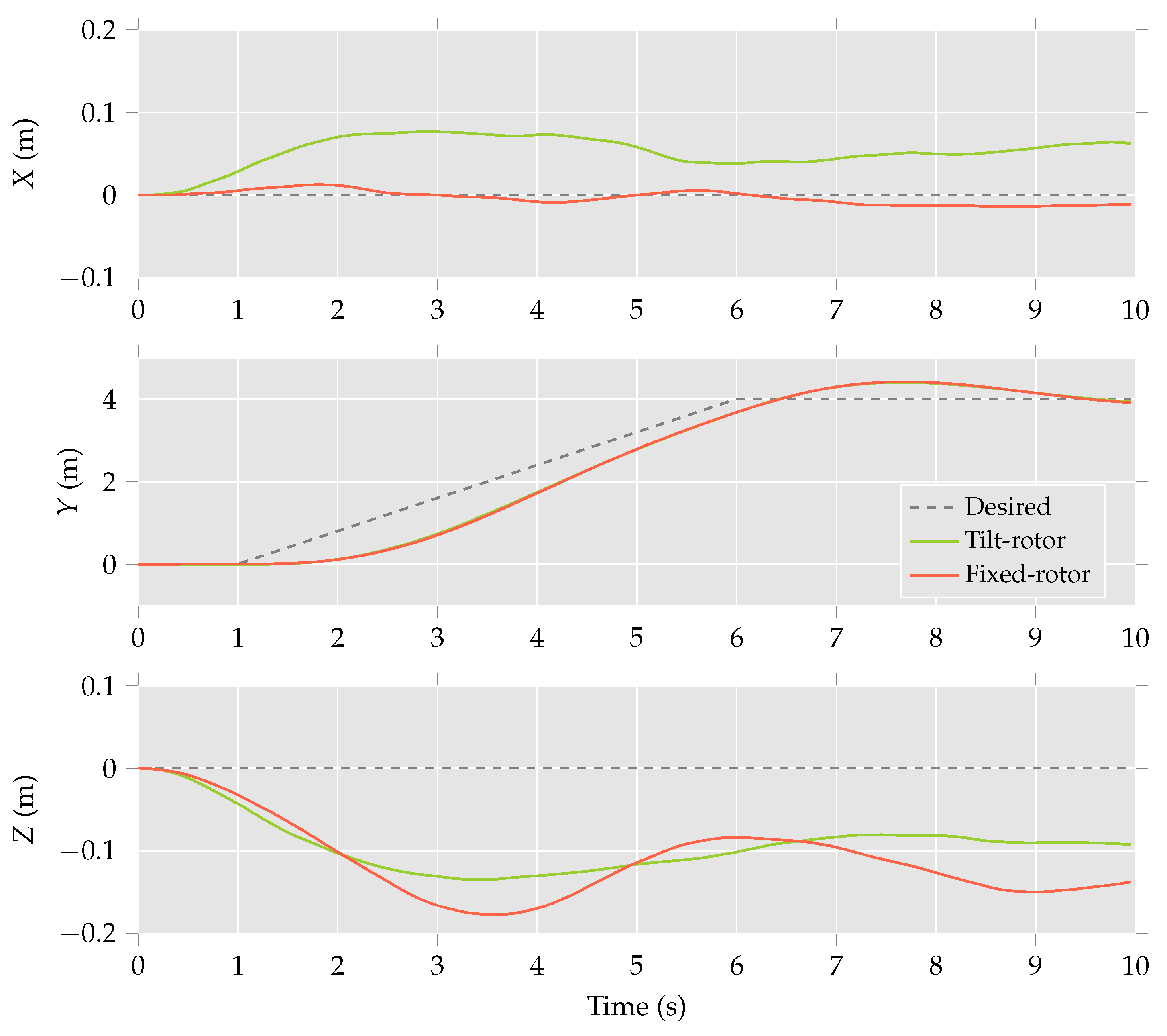
In the second experiment, the multirotor helicopter was commanded to track a step input of 1 m in the y-direction. The position and attitude of the multirotor helicopter during the second manoeuvre are presented in Figure 11 and Figure 12, respectively. As in the previous case, the differences in trajectories for the fixed and tilt-rotor are minimal. Further, it is observed that both multirotor helicopters were required to perform roll manoeuvres to track the desired position trajectory. However, the maximum roll for the tilt-rotor configuration was approximately 3 , compared to 7 in the case of the fixed-rotor configuration.
These results are in line with those predicted by the computational analysis. Further, these results suggest that a single tilting-rotor multirotor helicopter can be utilised to track trajectories involving horizontal accelerations that are independent of attitude.

7. Concluding Remarks

This paper presents the development and implementation of a single tilting-rotor multirotor helicopter. The dynamics model of such a multirotor helicopter is developed and presented in detail.
The identified dynamics model allows for the establishment of a feedback control system for the proposed multirotor helicopter. The control system provisions the desired control effort to the actuators of the system with the aim of minimising the attitude of the aerial vehicle while maintaining the desired trajectory.
A characterisation of the available control bandwidth of the single tilting-rotor multirotor helicopter is presented and demonstrates the validity of the proposed concept. Further, a computational analysis of the control system and complete dynamics model of the multirotor helicopter demonstrates that the control system allows for effective trajectory tracking while simultaneously minimising the attitude of the multirotor helicopter. The computational analysis is supported by an experimental analysis that compares the performance of the proposed multirotor helicopter to a multirotor helicopter with no tilting rotors. The experimental analysis demonstrates that the single tilting rotor multirotor helicopter is able to achieve comparable trajectory tracking performance for low-speed manoeuvres without requiring a change in attitude. Thus, the attitude and horizontal accelerations have been decoupled for low-speed manoeuvres by the addition of a single tilting rotor.
Further research will be undertaken to explore the full capabilities of the proposed single tilting rotor multirotor helicopter.

Author Contributions

Robert Porter and Bijan Shirinzadeh developed the single tilt-rotor multirotor helicopter and control system architecture, and conceived and designed the experimental analysis; Robert Porter performed the experimental analysis; Man Choi aided in the development of the experimental research platform and control system architecture.

Conflicts of Interest

The authors declare no conflict of interest.

References

  1. Valavanis, K.P. Advances in Unmanned Aerial Vehicles: State of the Art and the Road to Autonomy; Springer Science & Business Media: Berlin/Heidelberg, Germany, 2008; Volume 33. [Google Scholar]
  2. Choi, M.H.; Shirinzadeh, B.; Porter, R. System identification-based sliding mode control for small scaled autonomous aerial vehicles with unknown aerodynamics derivatives. IEEE/ASME Trans. Mechatron. 2016, 21, 2944–2952. [Google Scholar] [CrossRef]
  3. Choi, M.; Porter, R.; Shirinzadeh, B. Comparison of attitude determination methodologies with low cost inertial measurement unit for autonomous aerial vehicle. In Proceedings of the 2013 IEEE/ASME International Conference on Advanced Intelligent Mechatronics, Wollongong, Australia, 9–12 July 2013; pp. 1349–1354.
  4. Cutler, M.; How, J.P. Actuator constrained trajectory generation and control for variable-pitch quadrotors. In Proceedings of the AIAA Guidance, Navigation, and Control Conference (GNC), Minneapolis, MN, USA, 13–16 August 2012.
  5. Doyle, C.; Bird, J.; Isom, T.; Kallman, J.; Bareiss, D.; Dunlop, D.; King, R.; Abbott, J.; Minor, M. An avian-inspired passive mechanism for quadrotor perching. IEEE/ASME Trans. Mechatron. 2013, 18, 506–517. [Google Scholar] [CrossRef]
  6. Grzonka, S.; Grisetti, G.; Burgard, W. A fully autonomous indoor quadrotor. IEEE Trans. Robot. 2012, 28, 90–100. [Google Scholar] [CrossRef]
  7. Lee, D.J.; Kaminer, I.; Dobrokhodov, V.; Jones, K. Autonomous feature following for visual surveillance using a small unmanned aerial vehicle with gimbaled camera system. Int. J. Control Autom. Syst. 2010, 8, 957–966. [Google Scholar] [CrossRef] [Green Version]
  8. Tayebi, A.; McGilvray, S. Attitude stabilization of a VTOL quadrotor aircraft. IEEE Trans. Control Syst. Technol. 2006, 14, 562–571. [Google Scholar] [CrossRef]
  9. Wang, X.; Shirinzadeh, B. Nonlinear multiple integrator and application to aircraft navigation. IEEE Trans. Aerosp. Electron. Syst. 2014, 50, 607–622. [Google Scholar] [CrossRef]
  10. Wang, X.; Shirinzadeh, B.; Ang, M.H. Nonlinear double-integral observer and application to quadrotor aircraft. IEEE Trans. Ind. Electron. 2015, 62, 1189–1200. [Google Scholar] [CrossRef]
  11. Porter, R.; Shirinzadeh, B.; Choi, M.H. Experimental analysis of variable collective-pitch rotor systems for multirotor helicopter applications. J. Intell. Robot. Syst. 2015, 83, 271–288. [Google Scholar] [CrossRef]
  12. Jayakody, H.; Katupitiya, J. An Adaptive Variable Structure Control methodology for attitude and position control of a Vectored Thrust Aerial Vehicle. In Proceedings of the 2015 IEEE International Conference on Advanced Intelligent Mechatronics (AIM), Busan, Korea, 7–11 July 2015; pp. 1014–1019.
  13. Yuan, W.; Katupitiya, J. Dynamic modelling and control of a vectored thrust aerial vehicle. In Proceedings of the 2013 IEEE/ASME International Conference on Advanced Intelligent Mechatronics (AIM), Wollongong, Australia, 9–12 July 2013; pp. 1361–1366.
  14. Cetinsoy, E. Design and simulation of a holonomic quadrotor UAV with sub-rotor control surfaces. In Proceedings of the 2012 IEEE International Conference on Robotics and Biomimetics (ROBIO), Guangzhou, China, 11–14 December 2012; pp. 1164–1169.
  15. Kendoul, F.; Fantoni, I.; Lozano, R. Modelling and control of a small autonomous aircraft having two tilting rotors. IEEE Trans. Robot. 2006, 22, 1297–1302. [Google Scholar] [CrossRef]
  16. Ryll, M.; Bülthoff, H.H.; Giordano, P.R. Modelling and control of a quadrotor UAV with tilting propellers. In Proceedings of the 2012 IEEE International Conference on Robotics and Automation (ICRA), St. Paul, MN, USA, 14–18 May 2012; pp. 4606–4613.
  17. Leishman, J.G. Principles of Helicopter Aerodynamics; Cambridge Aerospace Series; Cambridge University Press: New York, NY, USA, 2006. [Google Scholar]
  18. Bouabdallah, S.; Noth, A.; Siegwart, R. PID vs LQ control techniques applied to an indoor micro quadrotor. In Proceedings of the 2004 IEEE/RSJ International Conference on Intelligent Robots and Systems, 28 September–2 October 2004; Volume 3, pp. 2451–2456.
  19. Bresciani, T. Modelling, Identification and Control of a Quadrotor Helicopter. Master’s Thesis, Lund University, Lund, Sweden, 2008. [Google Scholar]
  20. Oppenheimer, M.W.; Doman, D.B.; Bolender, M.A. Control allocation for over-actuated systems. In Proceedings of the 14th Mediterranean Conference on Control and Automation, Ancona, Italy, 28–30 June 2006; pp. 1–6.
  21. Markley, F.L. Fast quaternion attitude estimation from two vector measurements. J. Guid. Control Dyn. 2002, 25, 411–414. [Google Scholar] [CrossRef]
  22. Porter, R.; Shirinzadeh, B.; Choi, M.H.; Bhagat, U. Laser interferometry-based tracking of multirotor helicopters. In Proceedings of the 2015 IEEE International Conference on Advanced Intelligent Mechatronics (AIM), Busan, Korea, 7–11 July 2015; pp. 1559–1564.
  23. Martin, P.; Salaün, E. Design and implementation of a low-cost observer-based attitude and heading reference system. Control Eng. Pract. 2010, 18, 712–722. [Google Scholar] [CrossRef]
  24. Cominos, P.; Munro, N. PID controllers: Recent tuning methods and design to specification. IEE Proc. Control Theory Appl. 2002, 149, 46–53. [Google Scholar] [CrossRef]
Figure 1. The proposed single tilt-rotor multirotor helicopter.
Electronics 05 00081 g001
Figure 2. The maximum and minimum values of u T y that can be achieved given a set of u T z and u τ . Note that u τ y = u τ z = 0 (Nm).
Electronics 05 00081 g002
Figure 3. The maximum and minimum values of u T y that can be achieved given a set of u T z and u τ . Note that u τ x = u τ z = 0 (Nm).
Electronics 05 00081 g003
Figure 4. The maximum and minimum values of u T y that can be achieved given a set of u T z and u τ . Note that u τ x = u τ y = 0 (Nm).
Electronics 05 00081 g004
Figure 5. Multirotor helicopter position.
Electronics 05 00081 g005
Figure 6. Multirotor helicopter attitude.
Electronics 05 00081 g006
Figure 7. Lateral thrust produced by the multirotor helicopter and tilt-rotor tilt angle.
Electronics 05 00081 g007
Figure 8. Single tilt-rotor multirotor helicopter in flight.
Electronics 05 00081 g008
Figure 9. Multirotor helicopter position throughout the first manoeuvre.
Electronics 05 00081 g009
Figure 10. Multirotor helicopter attitude throughout the first manoeuvre.
Electronics 05 00081 g010
Figure 11. Multirotor helicopter position throughout the second manoeuvre.
Electronics 05 00081 g011
Figure 12. Multirotor helicopter attitude throughout the second manoeuvre.
Electronics 05 00081 g012
Table 1. Nomenclature.
SymbolDescription
BMultirotor helicopter body
F B Coordinate system attached to B
F B O Origin of F B
F E Earth-fixed coordinate system
F P Coordinate system attached to P
F P O Origin of F P
g Gravity vector in F E
I B Moment of inertia matrix of the multirotor helicopter
I R 0 Moment of inertia matrix of the tilting rotor
I R i Moment of inertia matrix of the i-th rotor
k D Trajectory PID control derivative action gain
k I Trajectory PID control integral action gain
k P Trajectory PID control proportional action gain
k T , i Rotor thrust constant
k τ , i Rotor torque constant
L P B Vector from F B to F P
L P i B Vector from F B to the i-th rotor
lDistance from F B O to the rotor hubs
mMass of the multirotor helicopter
PTilting rotor group
p Position of F B in F E
q P B Orientation of F P with respect to F B
q B E Orientation of F B with respect to F E
T 0 Thrust of the tilting rotor in F P
T 1 Attitude PD2 control gain
T 2 Attitude PD2 control gain
T 3 Attitude PD2 control gain
u T Thrust virtual control inputs
u τ Torque virtual control inputs
βTilt of P with respect to B
ω 0 Angular velocity of the tilting rotor in F P
ω 0 Angular velocity of the tilting rotor blade about F P Z
ω i Angular velocity of the i-th rotor about F B z
ω i Angular velocity of the i-th rotor in F E
ω B Angular velocity of F B with respect to F E
ω B P Angular velocity of F B with respect to F P
τ 0 Torque produced by the tilting rotor
τ i Torque produced by the i-th rotor
τ e x t 0 External torque applied to the tilting rotor
τ e x t i External torque applied to the i-th rotor
Table 2. Physical parameters for the single tilt-rotor multirotor helicopter.
I R 0 (Nm·s) I B xx (Nm·s) I B yy (Nm·s) I B zz (Nm·s)
5 . 824 × 10 5 1 . 773 × 10 2 1 . 880 × 10 2 3 . 461 × 10 2
m (kg) l (m) k τ (Nm·s2) k T (N·s2)
2 . 168 0 . 225 1 . 954 × 10 5 4 . 389 × 10 7
ω min (radian/s) ω max (radian/s) β min (radian) β max (radian)
52 . 4 890 . 1 1 . 57 1 . 57

