Wireless LAN-Based CSI Monitoring System for Object Detection


1
Access Network Service Systems Laboratories, NTT Corporation, Yokosuka 239-0847, Japan
2
Graduate School and Faculty of Information Science and Electrical Engineering, Kyushu University, Fukuoka 819-0395, Japan
*
Author to whom correspondence should be addressed.
†
These authors contributed equally to this work.
Electronics 2018, 7(11), 290; https://doi.org/10.3390/electronics7110290
Submission received: 27 September 2018
/
Revised: 23 October 2018
/
Accepted: 28 October 2018
/
Published: 1 November 2018
(This article belongs to the Special Issue Data Processing and Wearable Systems for Effective Human Monitoring)
Abstract
:Sensing services for the detection of humans and animals by analyzing the environmental changes of wireless local area network (WLAN) signals have attracted attention in recent years. In object detection using WLAN signals, a widely known technique is the use of time changes in received signal strength indicators that are easily measured between WLAN devices. Utilizing channel response, including power and phase values per subcarrier on multiple input multiple output (MIMO), the orthogonal frequency division multiplexing transmission was researched as channel state information (CSI) to further improve detection accuracy. This paper describes a WLAN-based CSI monitoring system that efficiently acquires the CSI of multiple links in a target area where multiple CSI measuring stations are distributed. In the system, a novel CSI monitoring station captures wireless packets sent within the area and extracts CSI by analyzing the packets on the sounding protocol, specified by IEEE 802.11ac. The paper also describes the system configuration and shows that indoor experimental measurements confirmed the system’s feasibility.
1. Introduction
The widespread use of mobile devices (e.g., smartphones, tablet personal computers, etc.) has explosively increased wireless communication traffic [1]. To stably and efficiently accommodate the massive amount of traffic, it is necessary to further improve system capacity on the current wireless communication systems (i.e., mobile and wireless local area network (WLAN) systems) [2,3,4,5]. Reusing the facilities of these systems has attracted attention because it enables other use scenarios of wireless signals to be developed, including sensing services that provide localization, object detection, and so on.
The Global Positioning System (GPS) was developed as an outdoor localization service for providing the positions of mobile devices, automobiles, and so on. This included the widespread development of GPS receivers that monitor multiple satellites and solve equations to determine the precise positions of objects by using deviations from true time. However, it is difficult to use the GPS in indoor environments where signals from satellites do not reach. Consequently, indoor localization services have been developed in which receiving power and arrival direction are calculated by using WLAN and/or Bluetooth signals and various sensors [6,7,8,9].
Other sensing services were studied in which objects (e.g., humans, animals, etc.) are detected by analyzing environmental changes of wireless signals and sensors [10,11,12,13]. It is widely known that object detection in WLAN systems can be achieved by analyzing environmental changes in the received signal strength indicator (RSSI). From analyzing the RSSI, the average receiving power within the frequency channel between WLAN devices [10,11,12] can be easily acquired at most WLAN devices with a small amount of information. This approach is widely used in the various object detection services. In the current evolution of machine learning techniques, research was done not only on object detection, but also on behavior detection (e.g., detecting biological activities and gestures) [12,13,14]. However, its detection accuracy is limited because RSSI is averaged by multiple components such as antennas and subcarriers. To further improve the accuracy, channel state information (CSI) was studied by utilizing channel responses, which included received power values per subcarrier on the orthogonal frequency division multiplexing (OFDM) transmission [13,14,15]. They also included relative values (power and phase information) between transmitter and receiver antennas via multiple input multiple output (MIMO) transmission [16]. However, as devices capable of outputting CSI exist mainly for research applications [17], it is difficult for general devices to acquire this function. Therefore, we consider that the utilization of general devices and efficient acquisition of CSI are issues to improve CSI monitoring, because the CSI to be acquired in the future will increase.
In this paper, we propose a WLAN-based CSI monitoring system that efficiently acquires the CSI of multiple links in a target area where multiple CSI measuring stations are distributed. In the proposed system, the CSI measuring stations assume the WLAN device specified by IEEE 802.11ac [18]. Then, a novel CSI monitoring station located in the target area captures wireless packets sent from measuring stations and extracts CSI by analyzing the CSI feedback frame specified by IEEE 802.11ac in the captured packets. Against issues described in previous paragraphs, to demonstrate the effectiveness of efficient CSI acquisition and the system’s feasibility based on indoor experimental results, we show a configuration of the system using general WLAN devices.
The remainder of the paper is organized as follows: Section 2 explains the very high throughput (VHT) sounding protocol specified by IEEE 802.11ac. Section 3 describes the proposed WLAN-based CSI monitoring system with a specific system configuration. Section 4 shows how indoor experimental results confirmed the system’s effectiveness. Finally, a summary is given in Section 5.
2. VHT Sounding Protocol Specified by IEEE 802.11ac
This section explains the VHT sounding protocol, which is the key elemen.t of the proposed system. Generally, transmit beamforming for single-user (SU) and multi-user (MU) MIMO transmissions requires knowledge of channel responses as CSI to calculate a pre-coding matrix that is applied to the transmitted signal to optimize reception at one or more receivers. Note that the IEEE 802.11ac specifies an explicit feedback mechanism in which the receiver directly estimates the channel responses per subcarrier from the training symbols transmitted by the transmitter, and sends back the CSI to the receiver via the VHT sounding protocol.
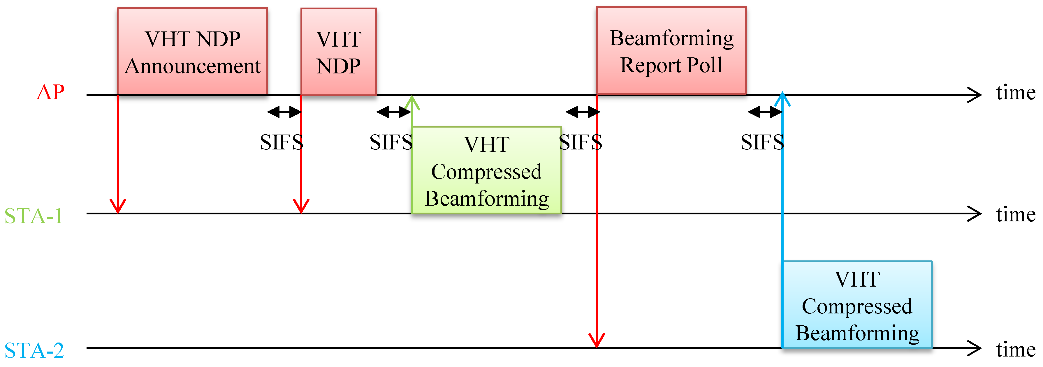
Figure 1 shows an example of the VHT sounding protocol for measuring the channel responses as CSI between WLAN access point (AP) and two WLAN stations, STA-1 and STA-2. This protocol is composed of a VHT null data packet (NDP) announcement, VHT NDP, VHT compressed beamforming, and beamforming report poll frames. In the protocol, AP transmits the VHT NDP announcement frame in order to call STA-1 and STA-2. AP continually broadcasts the VHT NDP frame to estimate the channel responses between AP and both STA-1 and STA-2. At the same time, STA-1 and STA-2 estimate the channel responses using the training symbols of the received VHT NDP frame. In addition, the estimated channel responses are compressed by the compression method specified by IEEE 802.11ac. Thereafter, STA-1 stores the compressed channel responses in the VHT compressed beamforming frame and feeds its CSI back to the AP. Next, STA-2 feeds back the CSI in accordance with the beamforming report poll frame of the AP. The detailed functions of each frame are described below.
2.1. VHT NDP Announcement and VHT NDP Frames
The VHT NDP announcement frame offers to call one or more stations that require the transmit beamforming for SU-MIMO or MU-MIMO transmissions by specifying the identification (ID) of the target station to the STA Info field within the VHT NDP announcement frame. The STA info field also includes the feedback type (SU or MU) and index, as well as Nc, the indicated column size of channel response matrixes. After transmitting the VHT NDP announcement frame, the VHT NDP frame including only the training symbols is continually broadcast to estimate the channel responses per subcarrier at the target station. In addition, as WLAN devices specified by IEEE 802.11ac are able to select a channel bandwidth such as 20, 40, 80, 80 + 80, and 160 MHz, the VHT NDP frame corresponding to each bandwidth can be transmitted.
2.2. VHT Compressed Beamforming Frame
Figure 2 shows a configuration of the VHT compressed beamforming frame as one of the management frames in IEEE 802.11ac. Figure 2a indicates a frame structure of the VHT compressed beamforming frame on the medium access control (MAC) layer. In the frame, the legacy field is from the beginning to the HT (high throughput) Control and the VHT field is from Category to the FCS (frame check sequence) as related to the CSI feedback in IEEE 802.11ac. In the VHT sounding protocol, the Category, VHT Action, and VHT MIMO Control fields are specified respectively as VHT, VHT compressed beamforming, and information for receiving CSI feedback. Note that detailed parameters were reported by Reference [18].
To decompress the compressed CSI to the channel responses per subcarrier in MIMO-OFDM transmission, the VHT MIMO Control field shown in Figure 2b includes the number of rows, Nr, and the number of columns, Nc, of the channel responses, the bandwidth (20, 40, 80, 80 + 80, 160 MHz), the grouping method (which is either all subcarriers or has 1–4 skipped subcarriers), the bit numbers (ϕ, ψ) of angle information of the compressed channel responses, and the feedback type (SU, MU). The compressed channel response is stored in the CSI field shown in Figure 2c. In the CSI field, the average signal-to-noise power ratio (SNR) values corresponding to each stream are sequentially stored in accordance with the SNR list in Table 1. Subsequently, angle information as shown in Table 2 of the channel response in each subcarrier is stored. Here, Na is the number of angle parameters and ϕ and ψ are angle information after compression.
The compression method specified by IEEE 802.11ac was explained in Reference [18]. Although a number of CSI compression techniques were researched, the feature of the compression method assumed in this paper is that the number of each element in the channel response matrix is reduced by applying the Givens rotation. In other words, this feature is a compression technique in the spatial axis rather than in the time and frequency axes. In addition, since the channel response to be compressed is aimed at the transmission beamforming on the transmission side, instead of feeding back, the matrix is fed back assuming that the eigenbeam weight is used. The matrix is a right singular matrix after singular value decomposition of the channel response as shown in Equation (1):
where is the channel response as the CSI, is a left singular matrix, and is a diagonal matrix with singular values of . Then, is calculated as shown in Equation (2) by using the Givens rotation.
is Nr × Nr diagonal matrix as shown in Equation (3):
is the Givens rotation matrix as shown in Equation (4):
where is the identity matrix, is the identity matrix in which zero is inserted in the missing element in the case of Nr ≠ Nc. The ϕ and ψ parameters are calculated by Equation (2) and quantized by Equation (5):
The matrix is decompressed from the notified angle information. Additionally, the number of quantization bits of ϕ and ψ differs between the SU and MU feedback types. For SU it is (bϕ and bψ) = (4, 2) or (6, 4) and for MU it is (bϕ and bψ) = (7, 5) or (9, 7).
2.3. Beamforming Report Poll Frame
The beamforming report poll frame offers to call a WLAN station that notifies CSI. The station receiving this frame and indicated via the Feedback Segment Retransmission Bitmap transmits CSI using the VHT compressed beamforming frame.
3. WLAN-Based CSI Monitoring System
3.1. System Configuration and System Flow
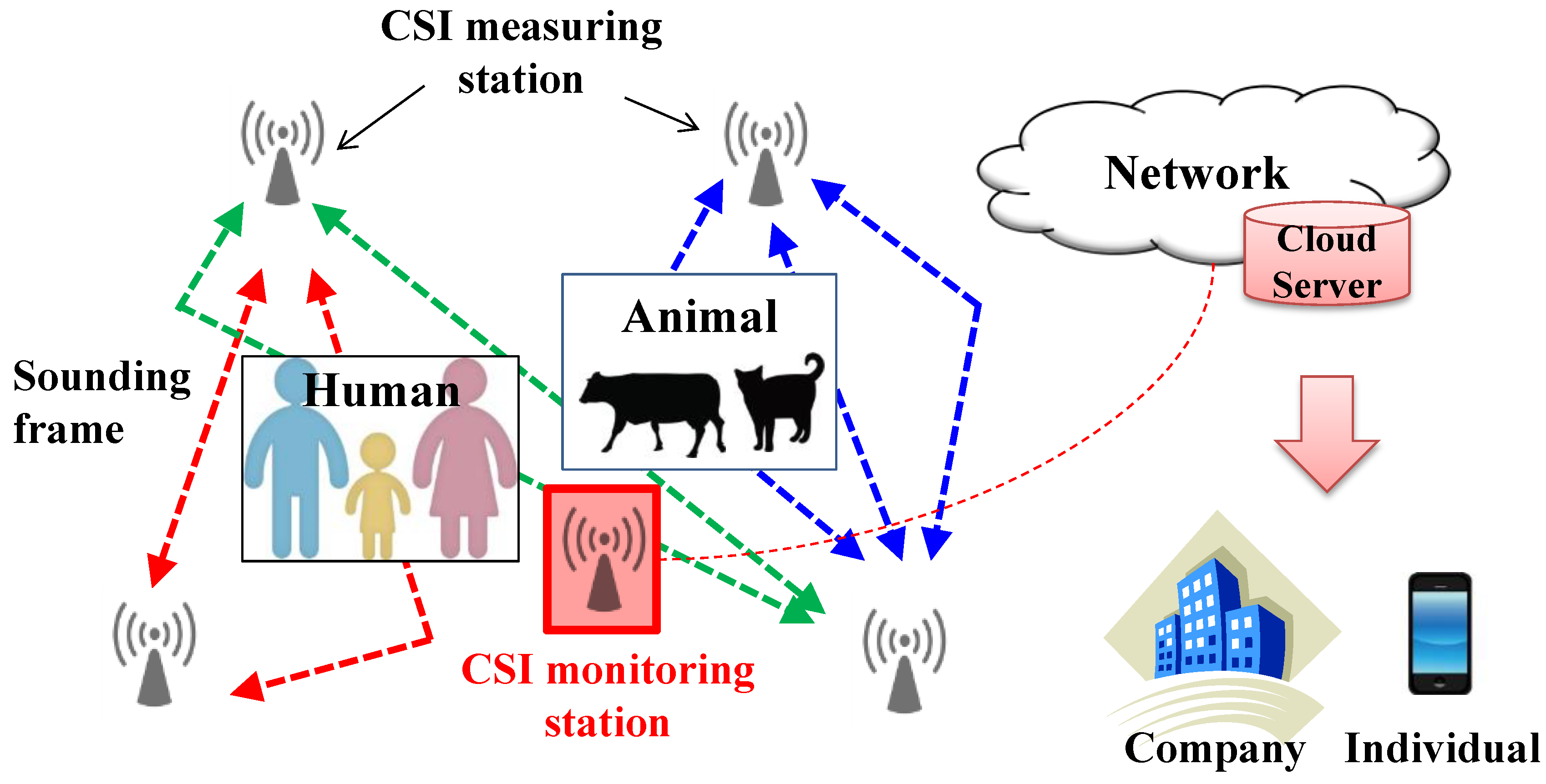
Figure 3 shows a concept of our proposed WLAN-based CSI monitoring system for detecting objects (humans or animals) in a target area. The system flow includes four steps: initialization, monitoring, transfer, and analysis.
At the initialization step, CSI measuring stations specified by IEEE 802.11ac are distributed in the target area. The system manages multiple CSI measuring stations, which are general devices without special specifications, and adjusts their locations in accordance with the movements and heights of the objects. Other parameters are also set in the CSI measuring stations, including the link connection, channel band, bandwidth, and transmit duration of the sounding frame. At the monitoring step, each CSI measuring station periodically exchanges the sounding frame via the VHT sounding protocol in accordance with the set parameters. At the same time, the CSI monitoring station located in the target area captures the wireless packets exchanged between the CSI measuring stations. It then extracts CSI by analyzing the sounding frame in the captured packets and decompressing the CSI to the channel responses per subcarrier in MIMO-OFDM transmission from acquired angle information as shown in Section 2. At the transfer step, the CSI monitoring station transfers the decompressed channel responses to a cloud server via backbone communication systems. However, when the transfer amount of CSI becomes huge, problems of backbone system load and detection delay occur. Therefore, for a practical system, the transfer amount must be suppressed by applying CSI coupling, other compression, and screening. Furthermore, when using a wireless communication system for the backbone system, it is important to transfer CSI in a short time by expanding the number of streams and bandwidth. At the analysis step, the cloud server analyzes the instantaneous channel responses stored in chronological order and outputs the detection results using machine learning techniques that create a learning model from statistical information of the pre-acquired CSI. Finally, the results are provided to companies and individuals.
3.2. Features of the Proposed System
This subsection describes features of the proposed system in terms of detection accuracy, total cost, and backbone load by comparing them with a conventional system that manages multiple CSI measuring stations without a CSI monitoring station. First, we consider that the proposed and conventional systems have equal detection accuracies because both systems manage multiple CSI measuring stations in the target area. On the other hand, the proposed system improves the total cost and backbone load more than the conventional system. In the latter system, each CSI measuring station requires a wireless or wired communication function to transfer the measured CSI from the CSI measuring station to the network cloud server. Therefore, costs due to the communication function increase at the CSI measuring station. Moreover, when the measured CSI is transferred to the cloud server, the transfer load of the backbone system becomes large. In particular, transmission efficiency may be lower for wireless communication than for wired communication, so further deterioration occurs.
However, in the proposed system the CSI measuring station does not require a communication function because the CSI monitoring station transfers the acquired CSI to the cloud server. Therefore, the CSI measuring station is simply based on the WLAN device. However, although a CSI monitoring station requires functions of communication, capture, memory, etc., the impact on total cost is small because there is only a single CSI monitoring station. In addition, CSI can be transferred efficiently since it is possible to apply SU-MIMO and MU-MIMO transmissions and use CSI acquisition stations with multiple antennas to achieve high transmission speed.
4. Performance and Feasibility Evaluations
4.1. Performance Evaluation
In this subsection, we describe the CSI measuring duration obtained in simulations for measuring CSI in the conventional and proposed systems. Note that CSI measuring duration is the time required for all stations to transfer CSI. The simulation parameters we used are listed in Table 3. The AP receives the signals from the CSI measuring station and the CSI monitoring station via wireless transmission. The bandwidth is 20 MHz and the AP, CSI monitoring station, and CSI measuring station have respectively four, four, and two antennas. In the conventional system, we assumed that in order to communicate with the stations of the cell edge, the transfer scheme between the AP and CSI measuring station is QPSK (Quadrature Phase Shift Keying), 1/2 convolutional rate, and two streams on MIMO transmission. In the proposed system, it is QPSK or 16QAM (Quadrature Amplitude Modulation), 1/2 convolutional rate, and two or four streams in MIMO transmission. The bit numbers, bϕ and bψ, for the CSI compression are respectively six and four. Figure 4 shows the duration results for measuring CSI when the pair number of CSI measuring stations increases from 1 to 100. As can be seen, for both systems the CSI measuring duration increases in proportion to the increased pair number of CSI measuring stations, but the proposed system has lower duration than the conventional system. This is because it is possible to notify the CSI collectively and the transmission rate can be set high. Even in the conventional system, it is possible to improve the transmission rate by increasing the number of antennas in the CSI measuring stations, but an increase in the total cost is disadvantageous. From this it can be expected that using the proposed system will not only enable CSI measuring duration time to be largely reduced, but will also enable the CSI measuring station cost to be decreased as described in Section 3. Moreover, since analysis of monitoring using CSI can be executed promptly by reducing these durations, real-time performance can be improved.
4.2. Feasibility Evaluation
In this subsection, we show the indoor experimental results obtained using our WLAN base CSI monitoring system to clarify the proposed system’s feasibility. Figure 5 shows the system configuration (the indoor experimental environment and equipment) where one WLAN AP (supported IEEE 802.11ac wave2) and two smartphones including WLAN chip (supported IEEE 802.11ac wave2) were deployed as the CSI measuring station. The number of AP and smartphone WLAN antennas were four and one respectively. The bandwidth and channel number were 20 MHz and 36ch (5 GHz) respectively. The CSI monitoring station, configured with a stick PC (Intel Compute Stick STK2m3W64CC, two antennas) and placed in the vicinity of the WLAN AP, captured wireless packets sent within the target area and extracted CSI by analyzing the packets on the VHT sounding protocol specified by IEEE 802.11ac. The experimental parameters used are outlined in Table 3. We conducted two types of experiments between the AP and smartphones, one with a person and one without a person.
First, to judge whether CSI was accurately acquired, an attenuator was connected directly under the AP antenna. Then, the SNR of the acquired CSI feedback frames was evaluated in accordance with the attenuation value. The measurement results (Figure 6; solid line) showed that the average SNR varied in proportion to the magnitude of the attenuation. Note that average SNR was stored in the CSI field described by Figure 2c. The result (ideal; dotted line) for ideal attenuation is also shown in Figure 6. As can be seen, when the attenuation value was from 10 to 30, we found that the average SNR decreased in proportion to the attenuation value. It can be seen from this result that SNR information could be accurately obtained from the captured packet. When the attenuation value was from 0 to 10 (high SNR), the measured SNR slightly shifted from ideal due to the effects of the dynamic range of the smartphone. However, since it communicates with a station that is relatively far away in a usual usage environment, it is possible to use it.
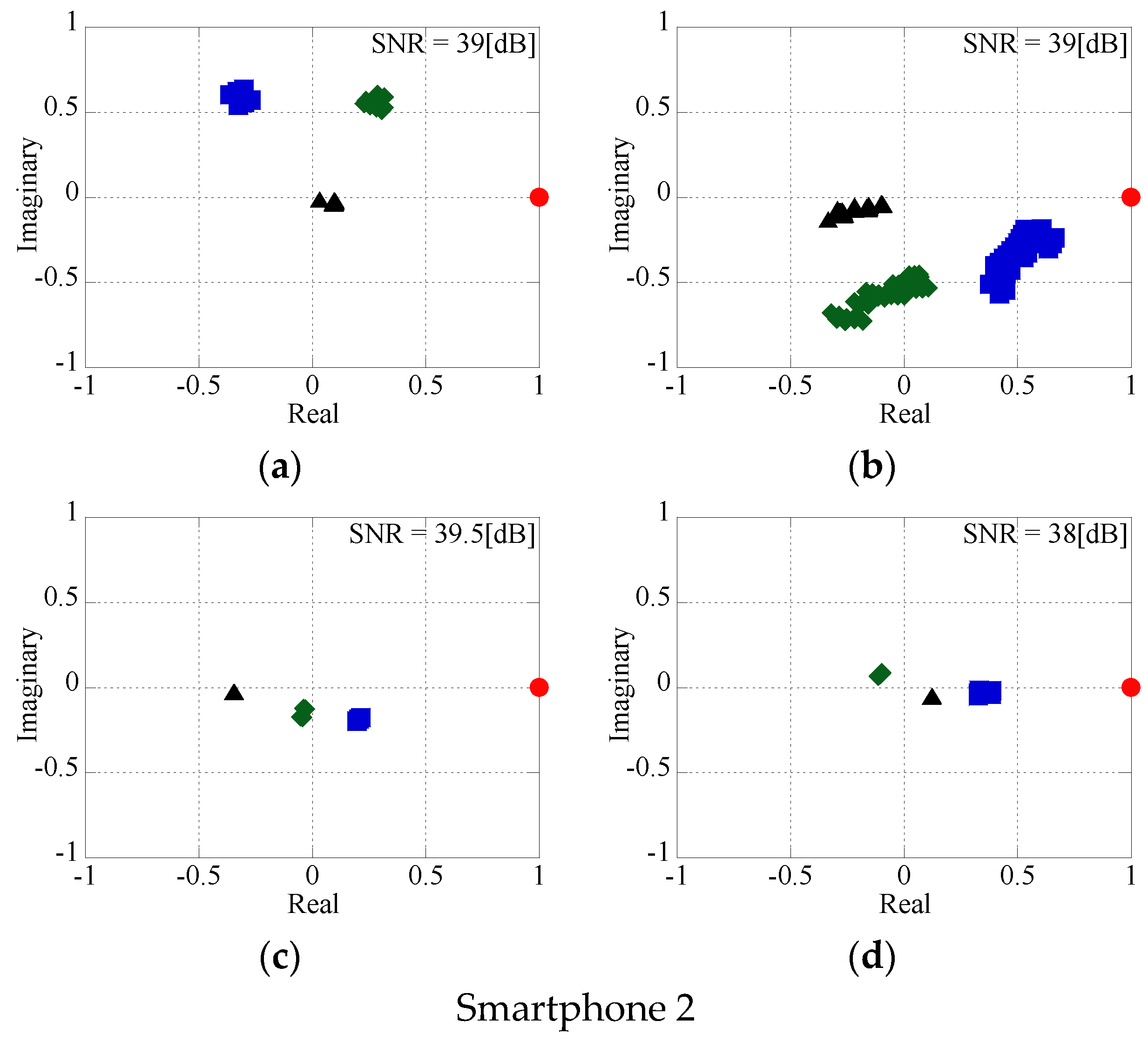
Second, Figure 7a–d show the results obtained in plotting each element of the channel matrix on the IQ plane when acquiring CSI with a human (Figure 7a,c) and without a human (Figure 7b,d). Figure 7a,b show the results obtained at different times (about 1 s) for smartphone 1, and Figure 7c,d show those for smartphone 2. Additionally, since the phase rotation occurs depending on the acquisition time, the results based on the fourth AP antenna are shown. From the results without a human in Figure 7a,c, it is considered that the channel matrix was successfully acquired because there was no temporal fluctuation of the propagation channel calculated from the captured packet. Then, from the results with and without a human in Figure 7a,b, it can be seen that the existence of a person changed each channel matrix element and also greatly changed its variation. On the other hand, it can be seen from the results of Figure 7c,d that while each channel matrix element changed somewhat due to the presence of a person, the changes were not significant from the viewpoint of fluctuation because there was no person in the path between AP and smartphone 2. These results confirmed the possibility of using CSI for monitoring based on general devices. Furthermore, it is possible to realize a monitoring system simply by applying machine learning to CSI acquired by the proposed system.
5. Conclusions
In this paper, we described the proposed wireless local area network-based channel state information (CSI) monitoring system that efficiently acquires CSI between IEEE 802.11ac devices in a target area. In the proposed system, a CSI acquisition station located in the target area acquires CSI in bulk by performing packet capturing and analyzing CSI feedback frames that are regularly exchanged between devices. We indicated the practicality of the proposed system by introducing a system configuration, including general devices and software. Moreover, we confirmed the system’s effectiveness from indoor experimental results using the proposed system.
In future works, we will apply machine leaning techniques to the proposed system and consider compression methods of CSI at monitoring stations for further high-efficiency transmission.
Author Contributions
T.M., S.I., and A.F. designed the proposed scheme; T.M. and M.M. performed the experiments and analyzed the results.
Funding
This research received no external funding.
Conflicts of Interest
The authors declare no conflict of interest.
References
- Cisco Visual Networking Index: Global Mobile Traffic Forecast Update. Available online: https://www.cisco.com/c/en/us/solutions/collateral/service-provider/visual-networking-index-vni/mobile-white-paper-c11-520862.pdf (accessed on 26 September 2018).
- Andrews, J.G.; Buzzi, S.; Choi, W.; Hanly, S.V.; Lozano, A.; Soong, A.C.; Zhang, J.C. What will 5G be? IEEE J. Sel. Areas Commun. 2014, 32, 1065–1082. [Google Scholar] [CrossRef]
- Shafi, M.; Molisch, A.F.; Smith, P.J.; Haustein, T.; Zhu, P.; Silva, P.D.; Tufvession, F.; Benjebbour, A.; Wunder, G. 5G: A tutorial overview of standards, trials, challenges, deployment, and practice. IEEE J. Sel. Areas Commun. 2017, 35, 1201–1221. [Google Scholar] [CrossRef]
- Deng, D.J.; Chen, K.C.; Cheng, R.S. IEEE 802.11 ax: Next generation wireless local area networks. In Proceedings of the IEEE International Conference on Heterogeneous Networking for Quality, Reliability, Security and Robustness, Rhodes, Greece, 18–20 August 2014; pp. 77–82. [Google Scholar]
- Khorov, E.; Kiryanov, E.; Lyakhov, A.; Bianchi, G. A Tutorial on IEEE 802.11ax High Efficiency WLANs. IEEE Commun. Surv. Tutor. 2018, 1–20. [Google Scholar] [CrossRef]
- Altintas, B.; Serif, T. Improving RSS-based indoor positioning algorithm via k-means clustering. In Proceedings of the European Wireless Conference on Sustainable Wireless Technologies, Vienna, Austria, 27–29 April 2011; pp. 1–5. [Google Scholar]
- Youssef, M.A.; Agrawala, A.; Shankar, A.U. WLAN location determination via clustering and probability distributions. In Proceedings of the IEEE International Conference on Pervasive Computing and Communications, Fort Worth, TX, USA, 26–26 March 2003; pp. 143–150. [Google Scholar] [Green Version]
- Xue, W.; Qiu, W.; Hua, X.; Yu, K. Improved Wi-Fi RSSI measurement for indoor localization. IEEE Sens. J. 2017, 17, 2224–2230. [Google Scholar] [CrossRef]
- Xue, W.; Hua, X.; Li, Q.; Yu, K.; Qiu, W.; Zhou, B.; Cheng, K. A New Weighted Algorithm Based on the Uneven Spatial Resolution of RSSI for Indoor Localization. IEEE Access 2018. [Google Scholar] [CrossRef]
- Kaltiokallio, O.; Bocca, M. Real-time intrusion detection and tracking in indoor environment through distributed RSSI processing. In Proceedings of the IEEE International Conference on Embedded and Real-Time Computing Systems and Applications, Toyama, Japan, 28–31 August 2011; pp. 61–70. [Google Scholar]
- Mrazovac, B.; Bjelica, M.Z.; Kukolj, D.; Todorovic, B.M.; Samardzija, D. A human detection method for residential smart energy systems based on ZigBee RSSI changes. In Proceedings of the 2012 IEEE International Conference on Consumer Electronics (ICCE), Las Vegas, NV, USA, 13–16 January 2012. [Google Scholar]
- Booranawong, A.; Jindapetch, N.; Saito, H. A System for Detection and Tracking of Human Movements Using RSSI Signals. IEEE Sens. J. 2018, 18, 2531–2544. [Google Scholar] [CrossRef]
- Pu, Q.; Gupta, S.; Gollakota, S.; Patel, S. Whole-home gesture recognition using wireless signals. In Proceedings of the ACM International Conference on Mobile Computing & Networking, Miami, FL, USA, 30 September–4 October 2013; pp. 27–38. [Google Scholar]
- Wang, Y.; Liu, J.; Chen, Y.; Gruteser, M.; Yang, J.; Liu, H. E-eyes: Device-free location-oriented activity identification using fine-grained wifi signatures. In Proceedings of the ACM International Conference on Mobile Computing and Networking, Maui, HI, USA, 7–11 September 2014; pp. 617–628. [Google Scholar]
- Yang, J.; Zou, H.; Jiang, H.; Xie, L. CareFi: Sedentary Behavior Monitoring System via Commodity WiFi Infrastructures. IEEE Trans. Veh. Technol. 2018, 67, 7620–7629. [Google Scholar] [CrossRef]
- Sasakawa, D.; Honma, N.; Nishimori, K.; Nakayama, T.; Shoichi, I. Evaluation of fast human localization and tracking using MIMO radar in multi-path environment. In Proceedings of the IEEE International Symposium on Personal, Indoor, and Mobile Radio Communications, Valencia, Spain, 4–8 September 2016; pp. 1–6. [Google Scholar]
- Linux 802.11n CSI Tool. Available online: https://dhalperi.github.io/linux-80211n-csitool/ (accessed on 26 September 2018).
- IEEE 802.11ac, Part 11: Wireless LAN Medium Access Control (MAC) and Physical Layer (PHY) specifications: Enhancements for Very High Throughput for Operation in Bands below 6 GHz, IEEE Std. Available online: https://ieeexplore.ieee.org/stamp/stamp.jsp?tp=&arnumber=6687187 (accessed on 26 September 2018).
Figure 1.
VHT sounding protocol specified by IEEE 802.11ac.

Figure 2.
Configuration of the VHT compressed beamforming frame. (a) Frame structure on MAC layer; (b) VHT MIMO Control field; (c) CSI field.
Figure 2.
Configuration of the VHT compressed beamforming frame. (a) Frame structure on MAC layer; (b) VHT MIMO Control field; (c) CSI field.

Figure 3.
Concept of the proposed system.

Figure 4.
Duration results for measuring CSI.

Figure 5.
System configuration.

Figure 6.
SNR characteristic.

Figure 7.
Channel matrix characteristic. (a) without human for Smartphone 1; (b) with human for Smartphone 1; (c) without human for Smartphone 2; (d) with human for Smartphone 2.
Figure 7.
Channel matrix characteristic. (a) without human for Smartphone 1; (b) with human for Smartphone 1; (c) without human for Smartphone 2; (d) with human for Smartphone 2.


Table 1.
SNR list.
| Value | Average SNR |
|---|---|
| −128 | ≤−10 dB |
| −127 | −9.75 dB |
| −126 | −9.5 dB |
| … | … |
| +126 | 53.5 dB |
| +127 | ≥53.75 dB |
Table 2.
List of ϕ and ψ.
| Size of Matrix (Nr × Nc) | Number of Angles (Na) | The Order of Angles |
|---|---|---|
| 2 × 1 | 2 | ϕ11, ψ21 |
| 2 × 2 | 2 | ϕ11, ψ21 |
| 3 × 1 | 4 | ϕ11, ϕ21, ψ21, ψ31 |
| 3 × 2 | 6 | ϕ11, ϕ21, ψ21, ψ31, ϕ22, ψ32 |
| 3 × 3 | 6 | ϕ11, ϕ21, ψ21, ψ31, ϕ22, ψ32 |
| 4 × 1 | 6 | ϕ11, ϕ21, ϕ31, ψ21, ψ31, ψ41 |
| 4 × 2 | 10 | ϕ11, ϕ21, ϕ31, ψ21, ψ31, ψ41, ϕ22, ϕ32, ψ32, ψ42 |
| … | … | … |
| 8 × 8 | 56 | ϕ11, ϕ21, ϕ31, ϕ41, ϕ51, ϕ61, ϕ71, … |
Table 3.
Simulation parameters.
| WLAN Standardization | IEEE 802.11ac |
|---|---|
| Pair number of the CSI measuring stations | 1~100 |
| Transfer scheme (conventional) | QPSK, 1/2 (convolutional rate), 2 streams |
| Transfer scheme (proposal) | QPSK or 16QAM, 1/2 (convolutional rate), 2 or 4 streams |
| Number of antennas: | |
| AP | 4 |
| CSI monitoring station | 4 |
| CSI measuring station | 2 |
| Bandwidth | 20 MHz |
| bϕ, bψ | 6, 4 |
© 2018 by the authors. Licensee MDPI, Basel, Switzerland. This article is an open access article distributed under the terms and conditions of the Creative Commons Attribution (CC BY) license (http://creativecommons.org/licenses/by/4.0/).
Share and Cite
MDPI and ACS Style
Murakami, T.; Miyazaki, M.; Ishida, S.; Fukuda, A. Wireless LAN-Based CSI Monitoring System for Object Detection. Electronics 2018, 7, 290. https://doi.org/10.3390/electronics7110290
AMA Style
Murakami T, Miyazaki M, Ishida S, Fukuda A. Wireless LAN-Based CSI Monitoring System for Object Detection. Electronics. 2018; 7(11):290. https://doi.org/10.3390/electronics7110290
Chicago/Turabian StyleMurakami, Tomoki, Masahiko Miyazaki, Shigemi Ishida, and Akira Fukuda. 2018. "Wireless LAN-Based CSI Monitoring System for Object Detection" Electronics 7, no. 11: 290. https://doi.org/10.3390/electronics7110290
Note that from the first issue of 2016, this journal uses article numbers instead of page numbers. See further details here.